Abstract
Background and Aim
The accuracy of the virtually-designed 3D-printed surgical splints requires investigation for the practical use of surgical plan in the operating room. This study aimed to compare the validity of the 3D-printed and the conventional intermediate splints and evaluate the outcomes after the surgical application of the 3D-printed splint compared with the predicted values.
Methods
In this study, ten patients with dentofacial deformity were recruited. Participants were analyzed by the conventional surgical planning and virtual surgical planning. The intermediate surgical splints were created by the conventional and 3D-printing methods. Maxillary movements in 3 spatial directions were measured in an articulator after the application of both splints. Correlation and agreement between the two methods were tested by intraclass correlation coefficient (ICC). After the confirmation of 3D printed splint validity for each patient, the surgery was performed using 3D printed splints. It is assumed that ideally cephalometric prediction values are going to be obtained using conventional acrylic splints (gold standard). So, as a second objective, the outcome of the surgically-applied 3D-printed splint was evaluated and compared with the predicted values and finally analyzed by the paired t-test.
Results
Based on the observations, there was an excellent agreement between the virtually-designed 3D-printed and conventional intermediate surgical splints (ICC ranged between 0.83 and 0.99 for linear values). There was a good cumulative agreement of ICC greater than 0.80. Overall, the mean linear measurements were not different between conventional and 3D-printed splint on the articulator. Also, there were no significant differences between the linear and angular measurements of 2D-cephalometric prediction and postoperation values.
Conclusion
The results showed cautiously the acceptable accuracy of the 3D-printed splints for several parameters in three spatial dimensions within the laboratory and clinical settings.
Keywords: Intermediate splint, 3D printed splints, Conventional surgical planning, Virtual surgical planning
Introduction
Orthognathic surgery is a common procedure in treatment of dentoskeletal malocclusions and abnormal bony performance associated with facial deformity. Le fort I osteotomy is also considered as the most common maxillofacial surgery for correction of the maxillary position in three spatial directions. Although the complexity of this procedure is well-defined, it requires high knowledge for the application in practice. The two-dimensional (2D) cephalometric analysis-based conventional treatment planning has a broad and well-established application in orthognathic surgery (1).
The intermediate surgical splints are used in orthognathic bimaxillary surgery to adjust the maxilla with the mandible, followed by a final splint to relocate the mandible in the final occlusal condition (2, 3). These splints have been made of acrylic resins along with 2D cephalometric tracing, on dental gypsum models, for many years and are still considered as the gold standard for effective orthognathic surgical planning performance. However, the application of conventional planning inherits some limitations as well (4). In recent years, the creation of an accurate 3D model in orthognathic surgical planning helped the construction of an appropriate intermediate splint (5, 6). The advancements of dentomaxillofacial imaging via three-dimensional (3D) imaging methods including laser face scanning, 3D-photographs, visual images, and especially cone-beam computed tomography (CBCT) led to the development of virtual surgical planning (VSP). The application of these techniques along with computer-aided design and computer-aided manufacturing (CAD/CAM) pushed the VSP even further (7–9). The 3D-printing technology allows the manufacturing of surgical splints by 3D-printers, improves surgical planning, and broadens the practical implications of surgical plans into the operating room (5, 10, 11).
Several studies have previously investigated the applications and implications of VSP in orthognathic surgery at different levels, ranging from a mere printing method for stone-replacing models to the fabrication of surgical splints during the procedure (8, 12). Also, the efficacy and accuracy of the 3D-printed splints on gypsum models and the patients has been discussed before (7, 8, 13, 14). Meanwhile, the accuracy of the 3D-printed intermediate splints on gypsum models and the patients remains to be explored. Therefore, this study aimed to assess the validity of the 3D-printed splints in comparison with the conventional splints (gold standard). As a second objective, the outcome of the surgically-applied 3D-printed splint was evaluated and compared with the predicted values.
Materials and Methods
Study Population
This study was conducted on ten patients aged 17–40 years with dentofacial deformity. All patients had a good health status. The patients were included if they had clinical and radiographic evidence of dentomaxillofacial deformities, were candidates of orthognathic surgery (bimaxillary or maxillary single jaw). The exclusion criteria were considered as Le Fort I segmental osteotomy and mandibular single jaw surgery requirement, any history of cleft lip and palate, and syndromic diagnosis. All operations were done by the same attending surgeon, who was highly-experienced in orthognathic surgery.
This study was in compliance with the World Medical Association Declaration of Helsinki on medical research and approved by the ethics committee of the Hospital. Information on the new and conventional methods were given to all patients and their families pre-operatively, and written informed consent was taken from all participants.
Impressions, Records, Imaging, and Surgical Planning
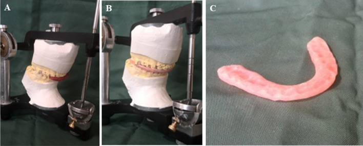
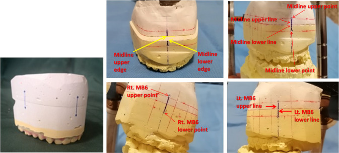
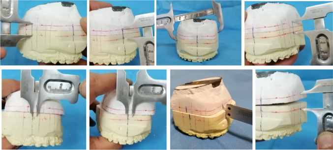
All orthognathic planning procedures followed the same pre-surgical instruction and included clinical and physical examinations. Two pairs of alginate impressions (Heraeus Kulzer, Hanau, Germany) were taken for both jaws and poured with Vel-Mix stone. The centric relation (CR) was defined by a registered bite using bite registration material (Occlufast Rock, Zhermack, Rovigo, Italy). The face-bow record was captured to reveal the spatial orientation of the maxilla in association with the skull base. Subsequently, the maxillary and mandibular casts were mounted on semi-adjustable articulators based on the face-bow record and CR registered bite. Individualized jigs were made from red compounds on the mounted models for the generation of patient-oriented CR simulation guide by the imaging procedure, and mount the second maxillary cast on the articulator, with regard to the same mandibular cast mounted before, as well (Fig. 1A and B). This has resulted in the creation of two analog maxillary plaster models in exactly the same relation with the mandibular one (CR). Custom fabrication of conventional acrylic splint was performed using the first mounted set (Fig. 1C). These conventional splints were used as controls for the evaluation of the 3D-printed splints' accuracy. The second mounted cast set was used for the measurement of the maxillary movements for both splints. The acrylic and 3D-printed splints were applied to this model to dictate the position of the maxillary cast. The 3D special displacement of maxilla was assessed using landmark points, lines and edges defined on casts (Figs. 2 and 3).
Fig. 1.
A Mounted plaster models in semi-adjustable articulators. B Created jig in centric relation to generate a CR simulation guide for patient while imaging procedure is going on. C Conventional acrylic splint, made on the first mounted set
Fig. 2.
Determined reference points, lines and edges on maxillary cast
Fig. 3.
Direct, real measurements of maxillary movements by defining the altered position of the maxillary cast
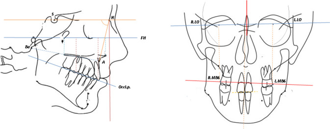
Radiographs, including lateral cephalogram, PA cephalogram, and CBCT (NewTom Inc., Verona, Italy) were captured in jig-dictated CR and natural head position (NHP). The first step to treatment planning was 2D cephalometric tracing and analysis. Maxillary orientation linear and angular measurements were recorded as variable values (Fig. 4). The required surgical actions were planned based on cephalometric and clinical values that were assessed as a pre-operation prediction procedure. To evaluate the accuracy of the predicted changes, the same procedure involving 3D-printed intermediate surgical splints was done postoperatively. The predicted actions were also done to the first maxillary mounted cast for the fabrication of the acrylic surgical intermediate splint.
Fig. 4.
Reference points and lines for cephalometric indices
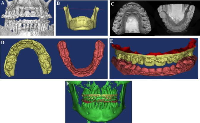
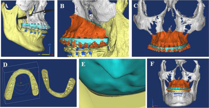
To create a 3D-virtual model, the CBCT imaging DICOM (Digital Imaging and Communications in Medicine) data were imported to Mimics-Materialise® (Materialise, Leuven, Belgium, version 6.0; Anatomage, San Jose, CA) 3D-imaging software environment. To replace the scattering and noisy dentition area on the 3D CBCT model that was caused by the metallic brackets and restorations of the patients, the upper and lower dentition area from stone casts were optically scanned using a high-resolution optical scanner (Ceramill Map 400; Amann Girrbach, Austria). These STL (Stereolithography)-formatted images were then imported into the Mimics-Materialise® software, and the point-based and surface-based registration methods were applied to superimpose the optically scanned dental models on the upper and lower jaw 3D-CBCT model (Fig. 5). Superimposition accuracy was assessed by Mimics corresponding tools within the ± 0.2 mm bias range and was corrected if needed (Fig. 6). After the completion of the image fusion process, virtual Le fort I osteotomy cuts were determined, and the required maxilla action was identified to establish intermediate occlusal relation. The virtual 3D surgical splint was designed in CATIA® software based on intermediate occlusal relation obtained after maxillary movements. A shelling technique was employed to obtain appropriate block-out for the perfect splint sit on dentition without interferences (Fig. 7).
Fig. 5.
A CBCT imaging in centric relation (CR), imported to the Mimics software environment, after noise corrections. B Defining the condylar axis of rotation. C Maxillary and mandibular plaster models, optically scanned. D Optically Scanned models, imported to the Mimics environment. E Registration of occlusion without noise and scattering, in Mimics software. F Hybrid models obtained from Fusion of 3D CBCT imaging model with optically scanned ones
Fig. 6.
A Fusion accuracy test. B Assessing favorite fusion accuracy after corrections. (green areas show optimal range for fusion accuracy) (color figure online)
Fig. 7.
A Osteotomy plane design. B Performing computer-assisted surgical simulation (CASS). C Maxillary final position. D intermediate splint designed by CATIA software. E A suitable blockout is obtained by shelling technique. F Intermediate splint virtually fitted in appropriate position
Prior to sending the STL file to a 3D printing laboratory (Eden260VS, Stratasys Objet, USA), an acrylic conventional intermediate surgical splint had been fabricated.
The 3D-printed and conventional splints were both fitted on the mandibular cast in the articulator sequentially. For each splint, the second maxillary cast was placed at the top and mounted on an articulator. The maxillary movements in three spatial dimensions were measured and recorded by a caliper with an accuracy of 0.1 mm to assess the maxillary movements after the application of both splints (Fig. 3). This measurement has also revealed the 3D-printed splint quality and validity for surgical purposes (Fig. 8). The final splints were made, if needed, but not assessed as variables in this study.
Fig. 8.
A Acrylic splint (left) and 3D printed splint (right). B Overally Assessment of the 3D printed splint for sitting quality on plaster models. C 3D printed splint
Surgery and Postoperative Analysis
The 3D-printed splints were transferred to the operating room once the validations were confirmed. Orthognathic surgery was performed under general anesthesia, with Le Fort l and BSSO (Bilateral Sagittal Split Osteotomy) osteotomies. The surgeon carried out maxillary Le Fort I osteotomy. The intermediate 3D-printed splint was fixed and the maxillary fixation was performed in the planned position by plates and screws. To compare the postoperative measurements with the predicted pre-operative values, patients were subjected to a second set of imaging at least one week after the operation, using PA (Postero-Anterior) and lateral cephalograms.
Statistical Analysis
Participant's characteristics are expressed as mean (standard deviation) for variables. A descriptive analysis of the measured variables was used to compare the similarity between 3D-printed and conventional surgical splints in the articulator. The Shapiro–Wilk test was used to assess the normality of data distribution, which was double-checked by the histogram. A paired t-test or a Wilcoxon test was used for normal or skewed variables, respectively. Matching results between the two methods of splint creation were qualified using the intra-class correlation coefficient (ICC). The Weir criteria were used to determine the reliability of the method (15). The data were statistically analyzed using SPSS version 16.0 (SPSS Inc, Chicago, IL, USA), and p < 0.05 was considered statistically significant.
Results
For this study, 10 patients (7 females and 3 males) were recruited and assessed by the surgeon performing the operations. Base on the data, the accuracy of the printed splints was acceptable. All participants have completed the surgery. The 3D-printed splints were successfully applied to all participants with a perfect sit. No complications or relapses were observed during the follow-up.
Table 1 represents the mean linear and angular measurements of each participant at baseline, and Table 2 illustrates the intraclass correlation coefficient of linear measurements between conventional and 3D-printed splints. The cumulative agreement between the conventional and printing methods was defined as ICC, and the coefficient greater than 0.80 was taken as a good agreement. The findings of ICC value with agreement measured linear and angular ranged from 0.83–0.99, indicating a high degree of agreement.
Table 1.
Baseline cephalometric linear and angular measurements in three dimensions for each patient
| Sagittal | Transverse | Vertical | ||||||||||
|---|---|---|---|---|---|---|---|---|---|---|---|---|
| Case# | Sex | Distance from Basion to A point | SNA | Distance from A point to Nprep | Distance from the midline to the perpendicular bisector of the left lateral orbital-right lateral orbital line(LLO-RLO)* | Distance from the right maxillary first molar buccal point to the perpendicular bisector of the left lateral orbital-right lateral orbital line(LLO-RLO) | Distance from the left maxillary first molar buccal point to the perpendicular bisector of the left lateral orbital-right lateral orbital line(LLO-RLO) | Distance from upper incisor edge to left lateral orbital-right lateral orbital line(LLO-RLO) | Distance from the right maxillary first molar buccal point to left lateral orbital-right lateral orbital line(LLO-RLO) | Distance from the left maxillary first molar buccal point to left lateral orbital-right lateral orbital line(LLO-RLO) | Distance from occlusal plan to FH plan in the incisor region | Distance from occlusal plan to FH plan in the first molar region |
| 1 | Male | 78.0 | 84.0 | 5.3 | 0.50 | 23.9 | 24.0 | 76.7 | 70.2 | 70.7 | 48.8 | 45.3 |
| 2 | Female | 69.50 | 78.0 | 8.0 | 0.70 | 23.3 | 24.8 | 70.3 | 96.0 | 58.6 | 42.4 | 35.3 |
| 3 | Male | 79.2 | 81.5 | − 2.1 | − 1.0 | 26.5 | 25.7 | 81.3 | 75.8 | 74.3 | 54.7 | 53.0 |
| 4 | Male | 87.4 | 77.0 | 4.4 | 2.4 | 23.4 | 29.5 | 94.3 | 88.0 | 86.0 | 62.3 | 60.0 |
| 5 | Female | 87.0 | 82.0 | 4.3 | 2.3 | 25.0 | 21.1 | 79.2 | 72.7 | 72.7 | 49.7 | 45.0 |
| 6 | Female | 87.5 | 85.0 | 1.7 | 0.6 | 24.6 | 22.6 | 80.2 | 71.2 | 71.4 | 54.4 | 43.9 |
| 7 | Female | 84.4 | 78.5 | 0.0 | 2.3 | 24.0 | 28.8 | 78.3 | 76.1 | 75.9 | 57.0 | 53.3 |
| 8 | Female | 88.2 | 86.0 | 8.8 | 0.3 | 24.1 | 25.0 | 73.0 | 69.5 | 69.2 | 50.4 | 47.1 |
| 9 | Female | 76.4 | 76.0 | 2.6 | 2.6 | 32.0 | 28.1 | 75.1 | 93.8 | 73.5 | 45.7 | 45.5 |
| 10 | Female | 70.0 | 77.0 | 7.0 | 1.3 | 25.4 | 26.4 | 83.3 | 75.6 | 73.9 | 51.3 | 47.3 |
Data are presented as mean
*the line drawn between left lateral orbital point and right lateral orbital point
Table 2.
Intraclass correlation coefficient (ICC) with 95% confidence interval for linear measurements on articulator, among 3D-printed and conventional splint
| Confidence interval at 95% | ||||
|---|---|---|---|---|
| ICC | Inferior limit | Superior limit | P-value | |
| Sagittal | ||||
| Right mesiobuccal maxillary first molar upper line to lower line | 0.861 | 0.439 | 0.965 | 0.004 |
| Left mesiobuccal maxillary first molar upper line to lower line | 0.872 | 0.486 | 0.968 | 0.003 |
| Midline upper to lower edge | 0.945 | 0.780 | 0.986 | < 0.001 |
| Transverse | ||||
| Right mesiobuccal maxillary first molar lower point to left mesiobuccal maxillary first molar upper point | 0.995 | 0.979 | 0.999 | < 0.001 |
| Left mesiobuccal maxillary first molar lower point to right mesiobuccal maxillary first molar upper point | 0.995 | 0.980 | 0.999 | < 0.001 |
| Midline upper to lower line | 0.832 | 0.287 | 0.956 | 0.008 |
| Vertical | ||||
| Right mesiobuccal maxillary first molar lower point to right mesiobuccal maxillary first molar upper point | 0.969 | 0.937 | 0.996 | < 0.001 |
| Left mesiobuccal maxillary first molar lower point to left mesiobuccal maxillary first molar upper point | 0.986 | 0.945 | 0.997 | < 0.001 |
| Midline upper to lower point | 0.993 | 0.972 | 0.998 | < 0.001 |
| Overall | 0.833 | 0.414 | 0.921 | < 0.001 |
According to Weir et al., an ICC between 0.8 and 1 indicates excellent reliability.(15)
Table 3 shows the overall differences of mean linear measurement in three dimensions between conventional and 3D-printed splints on the articulator. No significant differences were observed in any dimension of the measured parameters between the two splints. Table 4 represents the linear and angular measurement differences between the pre-operative data, cephalometric prediction and postoperative values. There were no significant differences between the linear and angular measurements of 2D cephalometric prediction and postoperative values, which confirms the accurate application of the 3D-printed splints in the operation.
Table 3.
Comparison of linear measurements on the articulator in three spatial dimensions between the 3D-printed and conventional splint
| Conventional splint | 3D printed splint | P value | |
|---|---|---|---|
| Sagittal | |||
| Right mesiobuccal point on the maxillary first molar upper line to lower line | 3.38 ± 2.08 | 2.83 ± 2.19 | 0.275 |
| Left mesiobuccal point on the maxillary first molar upper line to lower line | 3.65 ± 2.26 | 3.05 ± 2.11 | 0.230 |
| Midline upper to lower edge | 3.49 ± 2.41 | 2.83 ± 2.52 | 0.069 |
| Transverse | |||
| Right mesiobuccal maxillary first molar lower point to left mesiobuccal maxillary first molar upper point | 64.40 ± 3.44 | 64.37 ± 3.55 | 0.854 |
| Left mesiobuccal maxillary first molar lower point to right mesiobuccal maxillary first molar upper point | 63.62 ± 3.03 | 63.37 ± 3.55 | 0.139 |
| Midline upper to lower line | 0.40 ± 0.75 | 0.06 ± 0.70 | 0.090 |
| Vertical | |||
| Right mesiobuccal maxillary first molar lower point to right mesiobuccal maxillary first molar upper point | 14.80 ± 3.76 | 14.54 ± 3.49 | 0.386 |
| Left mesiobuccal maxillary first molar lower point to left mesiobuccal maxillary first molar upper point | 15.14 ± 4.25 | 14.72 ± 3.90 | 0.193 |
| Midline upper to lower point | 15.39 ± 4.31 | 15.36 ± 4.46 | 0.899 |
Data are presented as mean ± SD
Table 4.
Comparison of linear and angular measurements in three spatial dimensions between 2D cephalometric prediction and postoperation outcomes
| Postoperative | Prediction | P value | |
|---|---|---|---|
| Sagittal | |||
| Distance from Basion to A point | 83.68 ± 6.96 | 84.00 ± 7.24 | 0.196 |
| SNA | 83.40 ± 3.13 | 83.65 ± 3.12 | 0.657 |
| Distance from A point to Nprep | 3.08 ± 4.28 | 2.60 ± 4.74 | 0.315 |
| Transverse | |||
| Distance from the midline to the perpendicular bisector of the left lateral orbital-right lateral orbital line(LLO-RLO)* | 0.79 ± 1.00 | 0.41 ± 1.41 | 0.098 |
| Distance from the right maxillary first molar buccal point to the perpendicular bisector of the left lateral orbital-right lateral orbital line(LLO-RLO) | 24.72 ± 3.07 | 24.98 ± 2.57 | 0.631 |
| Distance from the left maxillary first molar buccal point to the perpendicular bisector of the left lateral orbital-right lateral orbital line(LLO-RLO) | 25.30 ± 3.13 | 24.55 ± 2.59 | 0.163 |
| Vertical | 0.859 | ||
| Distance from upper incisor edge to left lateral orbital-right lateral orbital line(LLO-RLO) | 78.39 ± 6.47 | 78.24 ± 5.40 | 0.456 |
| Distance from the right maxillary first molar buccal point to left lateral orbital-right lateral orbital line(LLO-RLO) | 71.19 ± 6.56 | 70.85 ± 6.19 | 0.312 |
| Distance from the left maxillary first molar buccal point to left lateral orbital-right lateral orbital line(LLO-RLO) | 70.87 ± 6.93 | 70.42 ± 6.51 | 0.514 |
| Distance from occlusal plan to FH plan in the incisor region | 49.90 ± 5.62 | 49.65 ± 4.78 | 0.752 |
| Distance from occlusal plan to FH plan in the first molar region | 45.70 ± 5.89 | 45.93 ± 5.72 | 0.620 |
Data are presented as mean ± SD
*the line drawn between left lateral orbital point and right lateral orbital point
Discussion
This study aimed to discuss the convergence between the conventional approach and the 3D-printing method in repositioning the maxilla as an intermediate orthognathic surgical guide. Given this, conventional and virtually-designed 3D-printed intermediate splints were used to apply surgical plans to patients with dentofacial deformity. Based on the findings, there was an 80% inter-class correlation coefficient, which compared to the conventional approach (gold standard), is a success of agreement and reasonable validity of the 3D-printed splints. The maxillary movements in the articulator were assessed for all patients after adjusting for both methods. Also, the outcome differences of the surgically-applied 3D-printed splint was evaluated and compared with the predicted values.
Several studies and technical notes have previously described the virtually-designed 3D-printed orthognathic surgical splint fabrication following virtual surgical planning (VSP) and CASS (Computer Aided Surgical Simulation) protocol assisted model surgeries (16–18). The efficiency and accuracy of modern orthognathic surgical splints, on the articulator and in clinical settings, have also been discussed (9, 12, 16, 19–21). Shaheen and colleagues (22) and Song Kyu and colleagues (23) have investigated the efficiency and accuracy of these splints on plaster models, while others have applied them to the patients during the operation (12, 20, 21). Shaheen and colleagues (22) have approved the clinically-acceptable error margins in assessing the accuracy of 3D-printed splints against the conventional models. A recent study (16) has indicated an acceptable validation for the 3D orthognathic surgical splints compared to the conventional models. Also, the results of another study by Song and colleagues showed a higher accuracy for the 3D-printed splints compared to the manual approach with an error of less than 1 mm, which was in the acceptable range (23). Results of this study did not show significant differences between the articulator measurements after the changes of deformity via the 3D-printed and conventional splints, which was in a line with the previous publications (13, 16, 23). These findings can confirm the clinical accuracy of both splints.
To the best of our knowledge, no studies have previously investigated the efficacy of 3D-printed splints in comparison with the conventional models on articulator and patients, successively. In this study, the accuracy of the 3D-printed splint on the articulator was initially assessed, and as the validity of the 3D-printed models was approved, they were applied to the patients, and the maxillary movements were compared with the predicted plan. No statistically significant differences were detected between the postoperative and predicted 2D cephalometric maxillary movement values, meanwhile, some measurements in the vertical dimension had a considerable variation, which is in agreement with the study of Cousley and colleagues (20). This could be explained by the nature of orthognathic surgical splints, surgical error, lack of control over the vertically dimensional movements during surgery, inadequate control on the condylar and mandibular position as a reference for the maxillary position, muscle relaxation during general anesthesia that may affect the mandibular position, and bony interferences at osteotomy site during advancement (20, 24, 25).
Changes in the vertical position of the maxilla by the orthognathic surgery are primarily dependent on the surgeon and the measuring tools rather than the intermediate splints. Therefore, creating reference points during surgery for the better control of the vertical dimension measurements is often recommended. In the current study, bony reference mark points were used on both sides of the maxillary osteotomy line to maintain this control. Notably, while comparing the postoperative and predicted values, a significant error of 5 mm in the anterior maxilla was observed in one patient. As no significant validation error was detected in the first step, this could be related to the concurrent advancement of more than 6 mm and the feasible effect on the relative position of the corresponding vertical reference points (bony mark points), lack of control on condylar and mandibular position, or bone interactions on both sides of the maxillary osteotomy line during the surgery.
Choosing the correct indicators that could reflect the maxillary position, and considering the stability and the possibility of adequate control over these indicators were of high importance. In the first step in this study, three points corresponding to the midline of the incisors and the mesiobuccal cusp of the first left and right maxillary molars on the articulator gypsum-mounted models were marked. The distance between the marks and the corresponding reference points on the gypsum model bases were measured by caliper. The evaluation of the 3D-printed intermediate splints on patients during the operation, and the comparison of the accuracy with the predicted treatment plan were also crucial. Therefore, in the second step, distance Ba-A, angular SNA, and A- Nprep were considered for linear and angular measurements in anteroposterior movements. In the vertical dimension, the Frankfurt plane, the occlusal plane, and the line between the left and right lateral orbital (LLO, RLO) points were used as reference. The line perpendicular to the LLO-RLO line was accounted as a reference line. The midline point between the incisors and the outermost point of the left and right first molars buccal surfaces were considered as well.
CBCT images show scattering in the presence of metallic orthodontic devices and restorative materials causing dentition and occlusal areas noisy, so cannot be used in VSP process (17).to register dentition properly, Dewaard and colleagues considered techniques such as limited field high resolution CBCT, Moire topography (plaster models laser scan), impression laser or CT scans and digital impressions by intraoral scanners. They addressed the fusion of digitalized plaster models with 3D reconstructed skull CBCT to improve accuracy in dentition registration. They also emphasized scant evolution of intraoral scanners and postulate analog impressions. They propound a 0.2 mm accuracy for voxel-based registration (voxel size = 0.2 * 0.2 * 0.2 mm) (17). Lin and colleagues used point-based registration for superimposition and believed that this method had acceptable clinical precision (24).
In present study we used point-based and surface-based registration techniques for plaster model scans and CBCT image fusion and considered an acceptable 0.2 mm bias for accuracy of superimposition.
In terms of work steps and sequences, corresponding literature showed major similarities and there were slight differences. In our study, work step sequences were accordingly committed, as described in methods section, except that, there is a comparative advantage in present study, in that, the accuracy of 3D printed splints is evaluated in two methods simultaneously, on articulator and on patient, which is less done in other studies.
In conclusion, the present results can discreetly illustrate the acceptable validation of the 3D-printed splint compared with the conventional approach in orthognathic surgery. Considering the broad use of the CASS protocol in orthognathic surgery and the complement application of 3D-printing technology in the pre-operative preparation stage, 3D-printed splints may be used in the operation room for routine clinical practices. To consider the clinical applicability and accuracy of 3D-printed splints, we have investigated the changes of the parameters in all three spatial dimensions in the laboratory and clinical settings. Future studies must concentrate on a larger study population and focus on each spatial dimension and range of movements as separate study groups.
Acknowledgments
No applicable
Authors' Contributions
FS and OT were responsible for study design, study concept, administration, data interpretation, recruitment. AJ and AF were responsible for drafting data interpretation, critical revision, statistical analysis and final approval of the article and literature review. FA was responsible for literature review. All authors have approved the final article and had important role in final approval of the article.
Funding
There is no funding.
Data Availability
Available.
Declarations
Conflict of interest
All authors declare that there is no conflict of interest in this study.
Ethical Approval and Consent to Participate
The study has been approved in Iranian Registry of Clinical Trials with Reference no: IRCT20170723035253N2.
Consent for Publication
Approved.
Footnotes
Publisher's Note
Springer Nature remains neutral with regard to jurisdictional claims in published maps and institutional affiliations.
References
- 1.Bailey LTJ, Cevidanes LH, Proffit WR. Stability and predictability of orthognathic surgery. Am J Orthod Dentofac Orthop. 2004;126(3):273–277. doi: 10.1016/j.ajodo.2004.06.003. [DOI] [PMC free article] [PubMed] [Google Scholar]
- 2.Metzger MC, Hohlweg-Majert B, Schwarz U, Teschner M, Hammer B, Schmelzeisen R. Manufacturing splints for orthognathic surgery using a three-dimensional printer. Oral Surg Oral Med Oral Pathol Oral Radiol Endodontol. 2008;105(2):e1–e7. doi: 10.1016/j.tripleo.2007.07.040. [DOI] [PubMed] [Google Scholar]
- 3.Adolphs N, Liu W, Keeve E, Hoffmeister B. RapidSplint: virtual splint generation for orthognathic surgery–results of a pilot series. Comput Aided Surg. 2014;19(1–3):20–28. doi: 10.3109/10929088.2014.887778. [DOI] [PMC free article] [PubMed] [Google Scholar]
- 4.Kusnoto B. Two-dimensional cephalometry and computerized orthognathic surgical treatment planning. Clin Plast Surg. 2007;34(3):417–426. doi: 10.1016/j.cps.2007.04.005. [DOI] [PubMed] [Google Scholar]
- 5.Zhang N, Liu S, Hu Z, Hu J, Zhu S, Li Y. Accuracy of virtual surgical planning in two-jaw orthognathic surgery: comparison of planned and actual results. Oral Surg Oral Med Oral Pathol Oral Radiol. 2016;122(2):143–151. doi: 10.1016/j.oooo.2016.03.004. [DOI] [PubMed] [Google Scholar]
- 6.Haas OL, Jr, Becker OE, de Oliveira RB. Computer-aided planning in orthognathic surgery-systematic review. Int J Oral Maxillofac Surg. 2015;44:329–342. doi: 10.1016/j.ijom.2014.10.025. [DOI] [PubMed] [Google Scholar]
- 7.Resnick CM, Inverso G, Wrzosek M, Padwa BL, Kaban LB, Peacock ZS. Is there a difference in cost between standard and virtual surgical planning for orthognathic surgery? J Oral Maxillofac Surg. 2016;74(9):1827–1833. doi: 10.1016/j.joms.2016.03.035. [DOI] [PubMed] [Google Scholar]
- 8.Hammoudeh JA, Howell LK, Boutros S, Scott MA, Urata MM. Current status of surgical planning for orthognathic surgery: traditional methods versus 3D surgical planning. Plast Reconstr Surg Glob Open. 2015;3(2):e307. doi: 10.1097/GOX.0000000000000184. [DOI] [PMC free article] [PubMed] [Google Scholar]
- 9.Zinser MJ, Sailer HF, Ritter L, Braumann B, Maegele M, Zoller JE. A paradigm shift in orthognathic surgery? A comparison of navigation, computer-aided designed/computer-aided manufactured splints, and “classic” intermaxillary splints to surgical transfer of virtual orthognathic planning. J oral Maxillofac Surg Off J Am Assoc Oral Maxillofac Surg. 2013;71(12):2151–e1. doi: 10.1016/j.joms.2013.07.007. [DOI] [PubMed] [Google Scholar]
- 10.Lee YC, Sohn HB, Kim SK, Bae OY, Lee JH. A novel method for the management of proximal segment using computer assisted simulation surgery: correct condyle head positioning and better proximal segment placement. Maxillofac Plast Reconstr Surg. 2015;37(1):21. doi: 10.1186/s40902-015-0023-3. [DOI] [PMC free article] [PubMed] [Google Scholar]
- 11.Pascal E, Majoufre C, Bondaz M, Courtemanche A, Berger M, Bouletreau P. Current status of surgical planning and transfer methods in orthognathic surgery. J Stomatol Oral Maxillofac Surg. 2018;119(3):245–248. doi: 10.1016/j.jormas.2018.02.001. [DOI] [PubMed] [Google Scholar]
- 12.Wrzosek MK, Peacock ZS, Laviv A, Goldwaser BR, Ortiz R, Resnick CM, et al. Comparison of time required for traditional versus virtual orthognathic surgery treatment planning. Int J Oral Maxillofac Surg. 2016;45(9):1065–1069. doi: 10.1016/j.ijom.2016.03.012. [DOI] [PubMed] [Google Scholar]
- 13.Steinhuber T, Brunold S, Gärtner C, Offermanns V, Ulmer H, Ploder O. Is virtual surgical planning in orthognathic surgery faster than conventional planning? A time and workflow analysis of an office-based workflow for single-and double-jaw surgery. J Oral Maxillofac Surg. 2018;76(2):397–407. doi: 10.1016/j.joms.2017.07.162. [DOI] [PubMed] [Google Scholar]
- 14.Lonic D, Lo L-J. Three-dimensional simulation of orthognathic surgery-surgeon's perspective. J Formos Med Assoc. 2016;115(6):387–388. doi: 10.1016/j.jfma.2015.09.002. [DOI] [PubMed] [Google Scholar]
- 15.Weir JP. Quantifying test-retest reliability using the intraclass correlation coefficient and the SEM. J Strength Cond Res. 2005;19(1):231–240. doi: 10.1519/15184.1. [DOI] [PubMed] [Google Scholar]
- 16.Shqaidef A, Ayoub AF, Khambay BS. How accurate are rapid prototyped (RP) final orthognathic surgical wafers? A pilot study. Br J Oral Maxillofac Surg. 2014;52(7):609–614. doi: 10.1016/j.bjoms.2014.04.010. [DOI] [PubMed] [Google Scholar]
- 17.de Waard O, Baan F, Verhamme L, Breuning H, Kuijpers-Jagtman AM, Maal T. A novel method for fusion of intra-oral scans and cone-beam computed tomography scans for orthognathic surgery planning. J Cranio-maxillo-facial Surg Off Publ Eur Assoc Cranio-Maxillo-Facial Surg. 2016;44(2):160–166. doi: 10.1016/j.jcms.2015.11.017. [DOI] [PubMed] [Google Scholar]
- 18.Yu H, Shen S, Wang X. The application of digital model surgery in the treatment of dento-maxillofacial deformities. Int J Oral Maxillofac Surg. 2015;44:e171. [Google Scholar]
- 19.Hsu SS, Gateno J, Bell RB, Hirsch DL, Markiewicz MR, Teichgraeber JF, et al. Accuracy of a computer-aided surgical simulation protocol for orthognathic surgery: a prospective multicenter study. J Oral Maxillofac Surg Off J Am Assoc Oral Maxillofac Surg. 2013;71(1):128–142. doi: 10.1016/j.joms.2012.03.027. [DOI] [PMC free article] [PubMed] [Google Scholar]
- 20.Cousley RRJ, Bainbridge M, Rossouw PE. The accuracy of maxillary positioning using digital model planning and 3D printed wafers in bimaxillary orthognathic surgery. J Orthod. 2017;44(4):256–267. doi: 10.1080/14653125.2017.1383708. [DOI] [PubMed] [Google Scholar]
- 21.Sun Y, Luebbers HT, Agbaje JO, Schepers S, Vrielinck L, Lambrichts I, et al. Accuracy of upper jaw positioning with intermediate splint fabrication after virtual planning in bimaxillary orthognathic surgery. J Craniofac Surg. 2013;24(6):1871–1876. doi: 10.1097/SCS.0b013e31829a80d9. [DOI] [PubMed] [Google Scholar]
- 22.Shaheen E, Sun Y, Jacobs R, Politis C. Three-dimensional printed final occlusal splint for orthognathic surgery: design and validation. Int J Oral Maxillofac Surg. 2017;46(1):67–71. doi: 10.1016/j.ijom.2016.10.002. [DOI] [PubMed] [Google Scholar]
- 23.Song KG, Baek SH. Comparison of the accuracy of the three-dimensional virtual method and the conventional manual method for model surgery and intermediate wafer fabrication. Oral Surg Oral Med Oral Pathol Oral Radiol Endod. 2009;107(1):13–21. doi: 10.1016/j.tripleo.2008.06.002. [DOI] [PubMed] [Google Scholar]
- 24.Lin HH, Lo LJ. Three-dimensional computer-assisted surgical simulation and intraoperative navigation in orthognathic surgery: a literature review. J Formos Med Assoc. 2015;114(4):300–307. doi: 10.1016/j.jfma.2015.01.017. [DOI] [PubMed] [Google Scholar]
- 25.Borba AM, Ribeiro-Junior O, Brozoski MA, Cé PS, Espinosa MM, Deboni MC, et al. Accuracy of perioperative mandibular positions in orthognathic surgery. Int J Oral Maxillofac Surg. 2014;43(8):972–979. doi: 10.1016/j.ijom.2014.04.017. [DOI] [PubMed] [Google Scholar]
Associated Data
This section collects any data citations, data availability statements, or supplementary materials included in this article.
Data Availability Statement
Available.


