Abstract
Objectives
This study aimed to analyze the biomechanics of cannulated screws (CS) with or without a lateral locking plate (LLP) in talar neck fractures through a finite element analysis.
Patients and methods
The computed tomography image of the talus from a healthy volunteer (adult male) was used to reconstruct a three-dimensional talar model. The method for fixing talar neck fractures with CS and an LLP was planned using computer-aided design software. Afterward, the three-dimensional models of comminuted talar neck fractures were used to simulate fixation with anteroposterior parallel dual CS, single CS+LLP, and dual CS+LLP. Finally, finite element analysis was carried out to compare the outcomes of dual CS+LLP to those of single CS+LLP and to those of using dual CS alone. The displacement and von Mises stress values of the three groups with different internal fixation were analyzed.
Results
For a simple talar neck fracture, the lowest amount of displacement was obtained with CS+LLP (0.407 mm), while dual CS (0.459 mm) showed the highest amount of total displacement; the lowest amount of peak stresses was obtained with CS+LLP (5.38 MPa), while dual CS (8.749 MPa) showed the highest amount of total peak stresses. For a comminuted talar neck fracture, the lowest amount of displacement was obtained with CS+LLP (0.398 mm), while dual CS (0.408 mm) showed the highest amount of total displacement; the lowest amount of peak stresses was obtained with CS+LLP (129.9 MPa), while dual CS (205.9 MPa) showed the highest amount of peak stresses.
Conclusion
Compared to the other two groups, the dual CS+LLP group had better biomechanics properties in the displacement and stress peak of the talus and implant. Thus, the use of dual CS+LLP fixation is recommended for the surgical treatment of comminuted talar neck fractures.
Keywords: Cannulated screws, finite element analysis, fixation, plate, talar neck fractures.
Introduction
Three to six percent of all foot fractures are talar fractures.[1] A previous study has shown that an isolated talar neck fracture is rare in computed tomography (CT) scans, and the majority of radiographic talar neck fractures are actually talar body fractures extending into the talus neck.[2] Among all talus fractures, talus body fractures are at 61%, head fractures are at 5%, and neck fractures are at 5%; 29% of talus fractures involved the neck and body, head, and neck, or all three components.[3] The common injury mechanism of a talar neck fracture is forced dorsiflexion of the ankle combined with axial loading, resulting in the anterior plafond edge impacting the talar neck.[4-6] Most injuries also involve a rotational force (hindfoot supination) causing dorsomedial talar neck comminution and a predilection of varus and extension malalignment of talar neck.[7] Currently, the treatment of comminuted talar neck fractures in adults remains challenging since this fracture has high rates of nonunion, malunion, osteonecrosis, and posttraumatic arthritis.[8] Therefore, satisfactory treatment for comminuted talar neck fractures requires anatomic reduction and rigid internal fixation.
The optimal treatment of displaced talar neck fractures remains controversial among orthopedic surgeons. Multiple cannulated screw (CS) fixation is commonly applied in displaced talar neck fractures.[9] However, due to shear forces, this procedure carries a high risk of failure, particularly in comminuted fractures.[10] Previously, the rate of malunion was approximately 30% in talar neck fractures.[11] The potential application of a lateral locking plate (LLP) to improve the fixation stability of talar neck fractures was first suggested by Fleuriau Chateau et al.[12] Charlson et al.[13] performed a biomechanical study to compare LLP and axial screw fixation in a transverse talar neck comminuted fracture model. They found that LLP fixation may be advantageous in that the anatomic alignment of comminuted talar neck fractures can be better controlled than in axial screw fixation. In a study of 23 patients, Fleuriau Chateau et al.[12] reported that plate fixation improved the ability to control the anatomic alignment of talar neck fractures and avoid malunion in comminuted fractures.
At present, there are few studies on the finite element analysis (FEA) of the CS fixation compared with the CS combined LLP fixation. Debate continues about the best internal fixation of talus neck fracture in clinical application. Hence, the aim of this study was to compare different internal fixation implants in treating talar neck comminuted fractures in terms of stability. The current study will help orthopedic surgeons to investigate practicality of LLP using FEA, thereby enabling appropriate treatment of talar neck fractures.
Patients and Methods
Modeling of the talar neck fracture
The finite element analysis study assessed a volunteer who was 176 cm in height and 65 kg in body weight with no history of lower extremity trauma or anatomical abnormalities, as determined by clinical examination using CT imaging with their feet in a neutral position during the scan, to create a three-dimensional model of a normal ankle joint. Parameters of the CT scan were as follows: section thickness, 0.5 mm; pitch, 1.375; tube voltage, 120 kV; matrix, 512x512. The resulting CT images were saved in DICOM (Digital Imaging and Communications in Medicine) format.
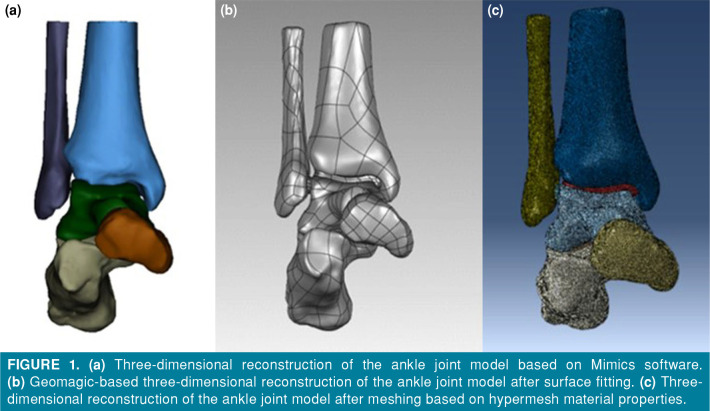
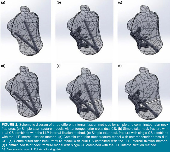
The ankle joint data in DICOM format were imported into Mimics 21.0 software (Materialise, Leuven, Belgium) for three-dimensional surface geometry reconstruction of periankle bones, including the scaphoid, fibula, tibia, calcaneus, and talus, using techniques such as region growth, threshold segmentation, and manual erase (Figure 1a). For each bone, data were converted into the .txt format and then transferred to Geomagic Studio 2014 software (Geomagic Company, Research Triangle Park, NC, USA), where the bones underwent processing such as unification, removal of external solitary points, noise reduction, surface fitting, and packaging to obtain their respective volumes (Figure 1b). In addition, cartilage was constructed in the corresponding bone spaces. The resulting entities were exported in IGES (Initial Graphics Exchange Specification) format, and simulation using the comminuted fracture models of the talar neck was performed using Solidworks software (Dassault Aviation, Paris, France). According to their real dimensions, a CS (the outside diameter of the CS is 4.0 mm) and an LLP (a five-hole 2.0-mm minifragment plate secured with 2.7-mm screws and contoured to the lateral surface of the talar neck) were constructed using Solidworks software. Next, simple talar fracture and comminuted talar fracture models were fixed by using three types of internal fixation. Six internal fixation models were established: anteroposterior cross dual CS or single/dual CS combined with LLP in simple talar fractures; dual CS or single/dual CS combined in LLP comminuted talar fractures (Figure 2). Each assembly was meshed with tetrahedral elements in Hypermesh 13.0 software (Altair Engineering Inc., Troy, MI, USA) (Figure 1c). Finally, the three-dimensional talar neck fractures models with their respective implant in ING format were imported into the FEA software (Abaqus version 6.14; Dassault Systèmes Simulia Corp., Johnston, RI, USA). The ligaments around the ankle joint were also simulated using spring units.
Figure 1. (a) Three-dimensional reconstruction of the ankle joint model based on Mimics software. (b) Geomagic-based three-dimensional reconstruction of the ankle joint model after surface fitting. (c) Threedimensional reconstruction of the ankle joint model after meshing based on hypermesh material properties.
Figure 2. Schematic diagram of three different internal fixation methods for simple and comminuted talar neck fractures. (a) Simple talar fracture models with anteroposterior cross dual CS. (b) Simple talar neck fracture with dual CS combined with the LLP internal fixation method. (c) Simple talar neck fracture with single CS combined with the LLP internal fixation method. (d) Comminuted talar neck fracture model with anteroposterior cross dual CS. (e) Comminuted talar neck fracture model with dual CS combined with the LLP internal fixation method. (f) Comminuted talar neck fracture model with single CS combined with the LLP internal fixation method. CS: Cannulated screws; LLP: Lateral locking plate.
Material properties
In this study, the material properties for the talar fracture model were defined in Abaqus version 6.14 by using the Hounsfield unit (HU) value of CT.[14] In turn, the material property types are categorized into 10 categories, and the elastic modulus assignment formula was determined using the density and HU values. Poisson's ratios are shown in Table I.[15] Homogeneous, continuous, isotropic, and linear elastomer material properties were assigned to tissues such as ankle cartilage and screws under quasistatic load. Based on the relevant literature,[16-19] the stiffness value of ligaments surrounding the ankle joint was determined to be 80 N/mm. The parameters of each component are listed in Table II, as per relevant literature references.[20,21]
Table 1. Material properties used in finite element models.
| Material | Element type | Young's modulus (MPa) | Poisson ratio |
| Bone | C3D4 | 13,800 | 0.3 |
| Cartilage | C3D4 | 10 | 0.4 |
| Internal fixation | C3D8R | 110,000 | 0.3 |
Table 2. The number of mesh and nodes of each finite element group.
| Group | Number of grid-point | Number of nodes |
| DCS | 4,145 | 1,221 |
| SCS+LLP | 1,235 | 3,562 |
| DCS+LLP | 1,256 | 3,563 |
| Tibial | 2,080 | 4,253 |
| Fibula | 2,518 | 1,181 |
| Calcaneus | 1,852 | 3,747 |
| Scaphoid | 1,027 | 2,110 |
| Talus | 3,306 | 6,908 |
| DCS: Dual cannulated screw; SCS: Single cannulated screw; LLP: Lateral locking plate. | ||
Boundary and loading conditions of the finite element models
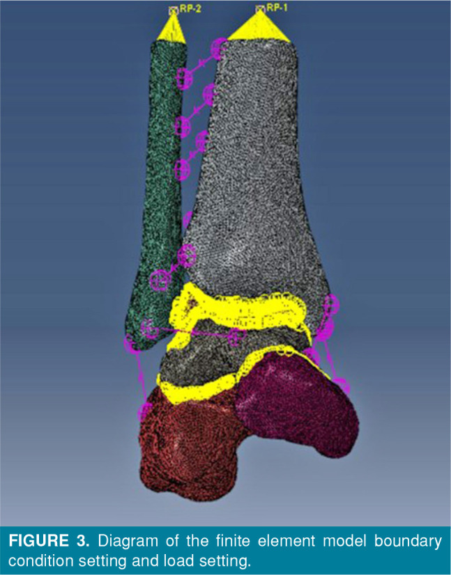
The contact method used in this study was based on references.[22,23] The ankle joint model contained bones, screws, ligaments, and cartilage. The contact boundary conditions between cartilage and bone surfaces were set as binding. The starting and ending points of the ligaments attached to bone were also set as binding. Force transmission between bones was achieved through the contact between cartilages. The contact condition between articular cartilages was set as friction, and the friction coefficient was 0.01 to simulate relative motion.[24] In the fracture model, a complete fracture of the talus was simulated, and the fracture surface remained in full contact after anatomical reduction. The fracture was rigidly fixed by simulated screws, and the fracture surfaces of the talus neck were set as friction with a friction coefficient of 0.34. The screws were bound to the bone. In this study, single-leg standing posture was simulated, and the constraint condition of the distal calcaneus was restrained and completely fixed. The scaphoid of the foot was free to move on the X axis and completely fixed on the Y and Z axes. A vertical downward load of 600 N (400% of body weight) was applied along the upper section of the tibia and fibula, with a tibiofibular ratio of 5:1. Figure 3 illustrates the setup.
Figure 3. Diagram of the finite element model boundary condition setting and load setting.
The FEA results of the intact ankle model and talar neck fracture model fixed by dual CS were predicted to validate the finite element model and in good consistency with previous literature.[25]
Indices of finite element calculation
The stress distributions, stress, and displacement peaks of simple talar fracture and comminuted talar fracture models were fixed with three types of internal fixation, including AP cross dual CS and single/dual CS combined LLP internal fixation methods.
Results
Von Mises stresses
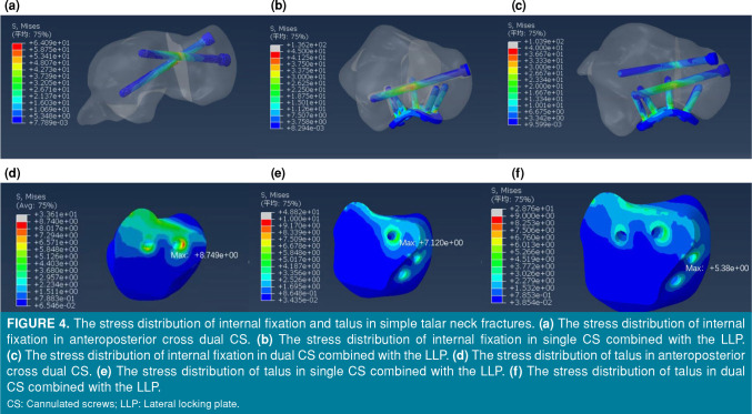
Differences in stress distribution were observed in the three groups of internal fixations. The peak stresses were concentrated at primary fracture line of the talus, which was adjacent to the slot of the implant. For a simple talar neck fracture, the peak stresses of the talus were 8.749 MPa, 7.12 MPa, and 5.38 MPa in the dual CS group, single CS+LLP group, and dual CS+LLP group, respectively (Table III and Figures 4a-c). For a comminuted talar neck fracture, the peak stresses of internal fixation were 205.9 MPa, 159.2 MPa, and 129.9 MPa in the dual CS group, single CS+LLP group, and dual CS+LLP group, respectively (Table 4 and Figures 5a-c).
Table 3. Parameters results of simple talar neck fractures.
| Parameters | DCS | SCS+LLP | DCS+LLP |
| Maximum talar stress (MPa) | 8.749 | 7.12 | 5.38 |
| Internal fixation maximum stress (MPa) | 64.09 | 136.2 | 103.9 |
| The maximum displacement of the talar (mm) | 0.408 | 0.406 | 0.398 |
| The maximum displacement of the internal fixation (mm) | 0.408 | 0.41 | 0.407 |
| DCS: Dual cannulated screws; SCS: Single cannulated screws; LLP: Lateral locking plate. | |||
Figure 4. The stress distribution of internal fixation and talus in simple talar neck fractures. (a) The stress distribution of internal fixation in anteroposterior cross dual CS. (b) The stress distribution of internal fixation in single CS combined with the LLP. (c) The stress distribution of internal fixation in dual CS combined with the LLP. (d) The stress distribution of talus in anteroposterior cross dual CS. (e) The stress distribution of talus in single CS combined with the LLP. (f) The stress distribution of talus in dual CS combined with the LLP. CS: Cannulated screws; LLP: Lateral locking plate.
Figure 5. The stress distribution of internal fixation and talus in comminuted talar neck fractures. (a) The stress distribution of internal fixation in anteroposterior cross dual CS. (b) The stress distribution of internal fixation in single CS combined with the LLP. (c) The stress distribution of internal fixation in dual CS combined with the LLP. (d) The stress distribution of talus in anteroposterior cross dual CS. (e) The stress distribution of talus in single CS combined with the LLP. (f) The stress distribution of talus in dual CS combined with the LLP. CS: Cannulated screws; LLP: Lateral locking plate.
Model displacement
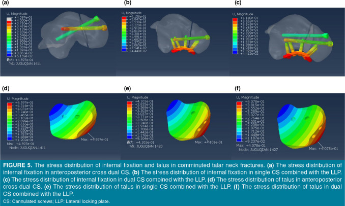
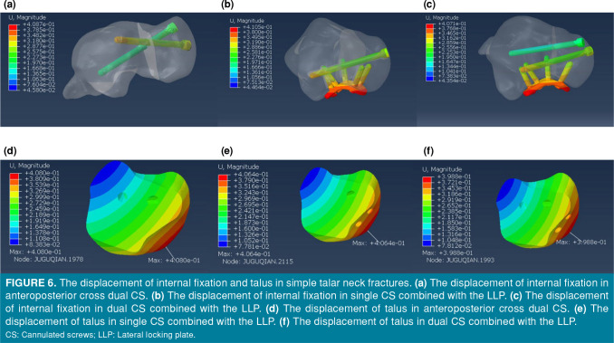
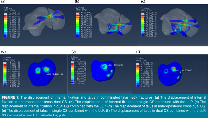
In model displacement, the dual CS+LLP group showed the lowest amount of displacement. For simple talar neck fractures, the maximum displacements at internal fixation were 0.408 mm, 0.41 mm, and 0.407 mm in the dual CS group, single CS+LLP group, and dual CS+LLP group, respectively (Table III and Figures 6a-c). The maximum displacements at the talus were 0.408 mm, 0.406 mm, and 0.398 mm in the dual CS group, single CS+LLP group, and dual CS+LLP group, respectively (Table III and Figures 6d-f). For comminuted talar neck fractures, the maximum displacements at internal fixation were 0.459 mm, 0.415 mm, and 0.414 mm in the dual CS group, single CS+LLP group, and dual CS+LLP group, respectively (Table IV and Figures 7a-c). The maximum displacements at the talus were 0.459 mm, 0.414 mm, and 0.407 mm in the dual CS group, single CS+LLP group, and dual CS+LLP group, respectively (Table IV and Figures 7d-f).
Table 4. Parameters results of comminuted talar neck fractures.
| Parameters | DCS | SCS+LLP | DCS+LLP |
| Maximum talar stress (MPa) | 21.01 | 19.01 | 15.07 |
| Internal fixation maximum stress (MPa) | 205.9 | 159.2 | 129.9 |
| The maximum displacement of the talar (mm) | 0.459 | 0.414 | 0.407 |
| The maximum displacement of the internal fixation (mm) | 0.459 | 0.415 | 0.414 |
| DCS: Dual cannulated screws; SCS: Single cannulated screws; LLP: Lateral locking plate. | |||
Figure 6. The displacement of internal fixation and talus in simple talar neck fractures. (a) The displacement of internal fixation in anteroposterior cross dual CS. (b) The displacement of internal fixation in single CS combined with the LLP. (c) The displacement of internal fixation in dual CS combined with the LLP. (d) The displacement of talus in anteroposterior cross dual CS. (e) The displacement of talus in single CS combined with the LLP. (f) The displacement of talus in dual CS combined with the LLP. CS: Cannulated screws; LLP: Lateral locking plate.
Figure 7. The displacement of internal fixation and talus in comminuted talar neck fractures. (a) The displacement of internal fixation in anteroposterior cross dual CS. (b) The displacement of internal fixation in single CS combined with the LLP. (c) The displacement of internal fixation in dual CS combined with the LLP. (d) The displacement of talus in anteroposterior cross dual CS. (e) The displacement of talus in single CS combined with the LLP. (f) The displacement of talus in dual CS combined with the LLP. CS: Cannulated screws; LLP: Lateral locking plate.
Discussion
Due to the complexity of peritalar anatomy, minimal displacement of the talar neck fracture may result in subtle incongruity of peritalar joints.[2] A previous biomechanical study concluded that a displacement of as little as 2 mm results in altered subtalar joint contact pressures, which can theoretically make the joint susceptible to post-traumatic arthrosis.[26] The combination of the anteromedial and anterolateral approaches avoids common complications, such as medial talar neck comminution or impaction, neck shortening, and malrotation. Cannulated screw fixation alone is reserved for simple talar neck fracture, in which case anatomic reduction can be obtained without comminution, which could lead to fracture collapse and malalignment. Lateral plating has become a popular and effective procedure of comminuted talar neck fractures. Lateral locking plates could be augmented with independent CS fixation as needed.[10,13] As expected, dual CS+LLP shows good biomechanical properties, therefore achieving optimum stability in terms of the minimum displacement. However, the difference in displacement at internal fixation and talus is thus quite unlikely to be the actual difference between groups. These should be considered when analyzing the present findings.
The optimal fixation methods for talar neck fractures remain controversial. Although anteroposterior dual CS fixation is commonly used, CS is located in an eccentric position, not perpendicular to the fracture line, and easily damages the talonavicular joint. Swanson et al.[27] performed a biomechanical study and found that posteroanterior screw fixation was stronger than anteroposterior screw fixation in a transverse noncomminuted talar neck fracture model. Fan et al.[19] compared posteroanterior CS fixation and anteroposterior CS in a transverse noncomminuted talar neck fracture FEA model and came to a similar conclusion. However, the posterolateral approach is limited to simple talar neck fractures for CS fixation, as it does not adequately visualize the talar neck and is associated with complications (injury to the peroneal artery, flexor hallucis longus tendon, or saphenous nerve; possible restriction of plantar flexion of the ankle from screw head impingement on the plafond; penetration of the sinus tarsi or subtalar joint).[28]
Unfortunately, clinical studies have reported that commonly used dual CS internal fixation often results in poor outcomes, such as nonunion and fixation failure. In a retrospective study, Fleuriau Chateau et al.[12] reported that plate fixation of comminuted talar neck fractures is a successful treatment that has been associated with a low complication rate. In the present study, screw placement avoided causing an injury to the talonavicular joint. Moreover, the additional LLP increases the biomechanical stability for comminuted talar neck fractures. Shear and rotational forces predominate, particularly in vertically displaced talar neck fractures, leading to toggling and rotation of the talar head. Therefore, it is vital that any fixation method resists these forces during the bone healing process.
Comminuted fractures have the highest risk of malunion. To expose the entire talar neck, the anteromedial and anterolateral approaches are currently advocated.[8,29] Rigid internal fixation is beneficial for comminuted fracture union. Therefore, the primary goal of internal fixation is to avoid redisplacement of the talar neck fracture. Anatomical reduction of comminuted fractures is more difficult, and subsequent malunion may lead to lateral column overload, subtalar arthritis, and decreased subtalar range of motion. Therefore, better stability is required to decrease the probability of these complications. Karakasli et al.[30] previously compared the biomechanical fixation strength of LLP fixation and headless CS fixation in a cadaveric talus model. They concluded that LLP fixation may be the preferred treatment for comminuted talar neck fractures. Previous FEA studies have only involved noncomminuted fracture models, but this study focuses on both noncomminuted and comminuted fracture models.[19,31] In present study, the peak stresses at internal fixation and talus in the dual CS+LLP group were smaller than those in the other two groups, which is beneficial for fracture healing.[31] The location of the talar neck fracture comminution dictates the LLP placement.
Limitations of the FEA method should not be neglected. For simplicity, we assumed the material properties of the talus, such as homogeneous and isotropic linear elasticity. Additionally, the fracture line in the fracture model was simple and irregular in the real clinical situation. Third, the researchers did not carry out an FEA after internal fixation of talar neck fractures under physiological loading conditions.
In conclusion, the peak von Mises stresses and displacements were the smallest in the dual CS+LLP fixation group, which had significantly improved results compared to the other two groups. Thus, the use of dual CS+LLP fixation is recommended for the surgical treatment of comminuted talar neck fractures.
Footnotes
Conflict of Interest: The authors declared no conflicts of interest with respect to the authorship and/or publication of this article.
Author Contributions: Material preparation: X.F., H.B.C., N.L.; Supervision: J.Q.H, Data collection and processing: X.F., H.B.C., N.L., Analysis and/or interpretation: X.F., G.X.W., Writing manuscript: X.F., G.X.W., Critical review: X.F., J.Q.H.
Financial Disclosure: This study was supported by funding from the Tianjin Science and Technology Committee (20JCZDJC00760).
References
- 1.Melenevsky Y, Mackey RA, Abrahams RB, Thomson NB 3rd. Talar fractures and dislocations: A radiologist’s guide to timely diagnosis and classification. Radiographics. 2015;35:765–779. doi: 10.1148/rg.2015140156. [DOI] [PubMed] [Google Scholar]
- 2.Dale JD, Ha AS, Chew FS. Update on talar fracture patterns: A large level I trauma center study. AJR Am J Roentgenol. 2013;201:1087–1092. doi: 10.2214/AJR.12.9918. [DOI] [PubMed] [Google Scholar]
- 3.Caracchini G, Pietragalla M, De Renzis A, Galluzzo M, Carbone M, Zappia M, et al. Talar fractures: Radiological and CT evaluation and classification systems. Acta Biomed. 2018;89(1-S):151–165. doi: 10.23750/abm.v89i1-S.7019. [DOI] [PMC free article] [PubMed] [Google Scholar]
- 4.Kenwright J, Taylor RG. Major injuries of the talus. J Bone Joint Surg [Br] 1970;52:36–48. [PubMed] [Google Scholar]
- 5.Canale ST, Kelly FB Jr. Fractures of the neck of the talus. Long-term evaluation of seventy-one cases. J Bone Joint Surg [Am] 1978;60:143–156. [PubMed] [Google Scholar]
- 6.Fortin PT, Balazsy JE. Talus fractures: Evaluation and treatment. J Am Acad Orthop Surg. 2001;9:114–127. doi: 10.5435/00124635-200103000-00005. [DOI] [PubMed] [Google Scholar]
- 7.Sproule JA, Glazebrook MA, Younger AS. Varus hindfoot deformity after talar fracture. Foot Ankle Clin. 2012;17:117–125. doi: 10.1016/j.fcl.2011.11.009. [DOI] [PubMed] [Google Scholar]
- 8.Vallier HA, Nork SE, Barei DP, Benirschke SK, Sangeorzan BJ. Talar neck fractures: Results and outcomes. J Bone Joint Surg [Am] 2004;86:1616–1624. [PubMed] [Google Scholar]
- 9.Halvorson JJ, Winter SB, Teasdall RD, Scott AT. Talar neck fractures: A systematic review of the literature. J Foot Ankle Surg. 2013;52:56–61. doi: 10.1053/j.jfas.2012.10.008. [DOI] [PubMed] [Google Scholar]
- 10.Attiah M, Sanders DW, Valdivia G, Cooper I, Ferreira L, MacLeod MD, et al. Comminuted talar neck fractures: A mechanical comparison of fixation techniques. J Orthop Trauma. 2007;21:47–51. doi: 10.1097/01.bot.0000247077.02301.d0. [DOI] [PubMed] [Google Scholar]
- 11.Canale ST, Kelly FB Jr. Fractures of the neck of the talus. Long-term evaluation of seventy-one cases. J Bone Joint Surg [Am] 1978;60:143–156. [PubMed] [Google Scholar]
- 12.Fleuriau Chateau PB, Brokaw DS, Jelen BA, Scheid DK, Weber TG. Plate fixation of talar neck fractures: Preliminary review of a new technique in twenty-three patients. J Orthop Trauma. 2002;16:213–219. doi: 10.1097/00005131-200204000-00001. [DOI] [PubMed] [Google Scholar]
- 13.Charlson MD, Parks BG, Weber TG, Guyton GP. Comparison of plate and screw fixation and screw fixation alone in a comminuted talar neck fracture model. Foot Ankle Int. 2006;27:340–343. doi: 10.1177/107110070602700505. [DOI] [PubMed] [Google Scholar]
- 14.Gao F, Chia K-S, Krantz I, Nordin P, Machin D. On the application of the von Mises distribution and angular regression methods to investigate the seasonality of disease onset. Stat Med. 2006;25:1593–1618. doi: 10.1002/sim.2463. [DOI] [PubMed] [Google Scholar]
- 15.Niu W, Yang Y, Yu G, Ding Z. Valid constructing method of three-dimensional finite element human foot model and experimental analysis on its rationality. Sheng Wu Yi Xue Gong Cheng Xue Za Zhi. 2009;26:80–84. [PubMed] [Google Scholar]
- 16.Siegler S, Block J, Schneck CD. The mechanical characteristics of the collateral ligaments of the human ankle joint. Foot Ankle. 1988;8:234–242. doi: 10.1177/107110078800800502. [DOI] [PubMed] [Google Scholar]
- 17.Hoefnagels EM, Waites MD, Wing ID, Belkoff SM, Swierstra BA. Biomechanical comparison of the interosseous tibiofibular ligament and the anterior tibiofibular ligament. Foot Ankle Int. 2007;28:602–604. doi: 10.3113/FAI.2007.0602. [DOI] [PubMed] [Google Scholar]
- 18.Beumer A, van Hemert WL, Swierstra BA, Jasper LE, Belkoff SM. A biomechanical evaluation of the tibiofibular and tibiotalar ligaments of the ankle. Foot Ankle Int. 2003;24:426–429. doi: 10.1177/107110070302400509. [DOI] [PubMed] [Google Scholar]
- 19.Fan Z, Ma J, Chen J, Yang B, Wang Y, Bai H, et al. Biomechanical efficacy of four different dual screws fixations in treatment of talus neck fracture: A threedimensional finite element analysis. J Orthop Surg Res. 2020;15:45–45. doi: 10.1186/s13018-020-1560-8. [DOI] [PMC free article] [PubMed] [Google Scholar]
- 20.Actis RL, Ventura LB, Smith KE, Commean PK, Lott DJ, Pilgram TK, et al. Numerical simulation of the plantar pressure distribution in the diabetic foot during the pushoff stance. Med Biol Eng Comput. 2006;44:653–663. doi: 10.1007/s11517-006-0078-5. [DOI] [PubMed] [Google Scholar]
- 21.MacLeod AR, Rose H, Gill HS. A validated open-source multisolver fourth-generation composite femur model. J Biomech Eng. 2016;138 doi: 10.1115/1.4034653. [DOI] [PubMed] [Google Scholar]
- 22.Samsami S, Saberi S, Sadighi S, Rouhi G. Comparison of three fixation methods for femoral neck fracture in young adults: Experimental and numerical investigations. J Med Biol Eng. 2015;35:566–579. doi: 10.1007/s40846-015-0085-9. [DOI] [PMC free article] [PubMed] [Google Scholar]
- 23.Chen WP, Tai CL, Shih CH, Hsieh PH, Leou MC, Lee MS. Selection of fixation devices in proximal femur rotational osteotomy: Clinical complications and finite element analysis. Clin Biomech (Bristol, Avon) 2004;19:255–262. doi: 10.1016/j.clinbiomech.2003.12.003. [DOI] [PubMed] [Google Scholar]
- 24.Anderson DD, Goldsworthy JK, Shivanna K, Grosland NM, Pedersen DR, Thomas TP, et al. Intra-articular contact stress distributions at the ankle throughout stance phase-patient-specific finite element analysis as a metric of degeneration propensity. Biomech Model Mechanobiol. 2006;5:82–89. doi: 10.1007/s10237-006-0025-2. [DOI] [PMC free article] [PubMed] [Google Scholar]
- 25.Capelle JH, Couch CG, Wells KM, Morris RP, Buford WL Jr, Merriman DJ, et al. Fixation strength of anteriorly inserted headless screws for talar neck fractures. Foot Ankle Int. 2013;34:1012–1016. doi: 10.1177/1071100713479586. [DOI] [PubMed] [Google Scholar]
- 26.Sangeorzan BJ, Wagner UA, Harrington RM, Tencer AF. Contact characteristics of the subtalar joint: The effect of talar neck misalignment. J Orthop Res. 1992;10:544–551. doi: 10.1002/jor.1100100409. [DOI] [PubMed] [Google Scholar]
- 27.Swanson TV, Bray TJ, Holmes GB Jr. Fractures of the talar neck. A mechanical study of fixation. J Bone Joint Surg [Am] 1992;74:544–551. [PubMed] [Google Scholar]
- 28.Shakked RJ, Tejwani NC. Surgical treatment of talus fractures. Orthop Clin North Am. 2013;44:521–528. doi: 10.1016/j.ocl.2013.06.007. [DOI] [PubMed] [Google Scholar]
- 29.Maher MH, Chauhan A, Altman GT, Westrick ER. The acute management and associated complications of major injuries of the talus. e2JBJS Rev. 2017;5 doi: 10.2106/JBJS.RVW.16.00075. [DOI] [PubMed] [Google Scholar]
- 30.Karakasli A, Hapa O, Erduran M, Dincer C, Cecen B, Havitcioglu H. Mechanical comparison of headless screw fixation and locking plate fixation for talar neck fractures. J Foot Ankle Surg. 2015;54:905–909. doi: 10.1053/j.jfas.2015.04.002. [DOI] [PubMed] [Google Scholar]
- 31.Atik OŞ. Which articles do the editors prefer to publish. Jt Dis Relat Surg. 2022;33:1–2. doi: 10.52312/jdrs.2022.57903. [DOI] [PMC free article] [PubMed] [Google Scholar]


