

Abstract
The pharmaceutical industry has traditionally relied on mass manufacturing to make its products. This has created multiple problems in the drug supply network, including long production times, inflexible and sluggish manufacturing and lack of personalized dosing. The industry is gradually adapting to these challenges and is developing novel technologies to address them. Continuous manufacturing and 3D printing are two promising techniques that can revolutionize pharmaceutical manufacturing. However, most research studies into these methods tend to treat them separately. This study seeks to develop a new processing route to continuously integrate a 3D printing platform (Drop-on-Demand, DoD, printing) with crystallization that is generally the final step of the active ingredient manufacturing. Accomplishing this integration would enable harnessing the benefits of each method- personalized dosing of 3D printing and flexibility and speed of continuous manufacturing.
A novel unit operation, three-phase settling (TPS), is developed to integrate DoD with the upstream crystallizer. To ensure on-spec production of each printed dosage, two process analytical technology tools are incorporated in the printer to monitor drug loading in manufactured drug products in real time. Experimental demonstration of this system is carried out via two case studies: the first study uses an active ingredient celecoxib to test the standalone operation of TPS; the second study demonstrates the operation of the integrated system (crystallizer – TPS – DoD) to continuously make drug products for the active ingredient- lomustine. A dissolution test is also performed on the manufactured and commercial lomustine drug products to compare their dissolution behavior.
Keywords: Additive manufacturing, modular continuous manufacturing, miniaturized pharmaceutical manufacturing platform, MiniPharm, distributed manufacturing, three-phase settling, personalized dosing, small-scale manufacturing
Introduction
Pharmaceutical manufacturing today is at an exciting crossroads, the conventional mass production techniques and complex supply chains that the industry has relied on for decades are being re-evaluated in response to the demands of present-day marketplace conditions, including the stresses imposed by the Covid pandemic. This has given a renewed impetus in both academia and industry to develop new processes and techniques to modernize this important manufacturing sector. Today the pharmaceutical industry faces several challenges in the domain of drug manufacturing- mitigating drug shortages, increasing process agility and flexibility to better absorb shocks in demand and to provide infrastructure to support emerging trends in healthcare like personalized medicine.1 Conventional pharmaceutical manufacturing practice involves producing the drug in large quantities in batch facilities with globalized supply chains. This style of production suffers from several limitations such as long manufacturing times, fragile supply chains and low process flexibility, which make it inadequate for meeting current challenges.2
Continuous manufacturing can address some of these concerns, bringing together process operations under one roof (end-to-end) and operating them continuously opens up a plethora of advantages. It increases manufacturing flexibility by allowing for variable production volumes and reducing plant footprint. End-to-end continuous (E2EC) manufacturing greatly shortens production time by eliminating inter-process hold up times, thereby increasing process agility. Production time is further shortened by incorporating in-line Process Analytical Technology (PAT) tools, these tools enable monitoring critical quality attributes (CQAs) of the product in real time. Thus, quality is built into the product and the need for lengthy postprocessing quality checks is reduced.2–4 Furthermore, designing E2EC units as modular small-scale facilities allows for deploying them as mini-plants to serve local populations. These continuous mini-plants can be operated as a part of a distributed manufacturing network, which enables a robust drug supply chain that can withstand demand shocks caused by pandemics, natural disasters and other emergencies.5,6 Many studies have explored the development of such mini plants and have shown successful results in integrating upstream operations (to synthesize the drug substance) like reaction and crystallization and running them continuously.7–10
Another pressing need in pharmaceutical manufacturing is to design platforms that can support emerging therapy techniques in healthcare like personalized medicine. Personalizing the drug dose prescribed to each patient engenders several outcome benefits. It minimizes the risk of over and under dosing and in the case of drugs with narrow therapeutic window, it reduces serious adverse drug reactions. 3D printing (3DP) or additive manufacturing has emerged as a key enabler for personalized dosing. 3DP of pharmaceuticals involves manufacturing the drug product in a layer-by-layer fashion with a focus on precise but flexible drug dosing. It imparts late stage product customization capability to the manufacturing process, i.e., it allows to manufacture drug products with variable drug loading without having to alter any of the upstream manufacturing steps.11,12
In recent years, 3DP has gained significant popularity in the pharmaceutical manufacturing community and multiple techniques have been developed to execute it. These can be broadly classified into three categories: 1) Powder bed printing- here a mixture of the active pharmaceutical ingredient (API) and excipient is spread layer-by-layer, a binder solution is printed over each layer and solidified to make the drug product. The first 3D printed drug approved by the United States Food and Drug Administration (FDA), Spritam®, used this technique. 2) Extrusion printing: here the idea is to compress the API-excipient formulation into a filament and then extrude it into the desired shape at elevated temperatures. 3) Inkjet printing: here the API is processed with a liquid carrier and printed as drops over a substrate. The carrier is then either solidified with the API or evaporated off.13 Each technique has its own benefits and disadvantages but the key drawback common to all is the lack of widespread commercial adoption. The primary drivers for adoption of pharmaceutical 3DP are dose strength flexibility, on-demand manufacturing and decentralized production capability.14 Implementation of pharmaceutical 3DP has largely tended to ignore the latter two. This coupled with a variety of technical challenges like: on-site production of precursor formulation, powder handling problems- improper feeding, scraping and clogging and lack of regulatory guidance on manufacturing process and quality testing considerations etc. has led to reduced adoption.13 Many of these challenges can be addressed by making 3DP continuous15,16 and integrating it with upstream API synthesis steps. On-demand manufacturing and decentralized production can only be truly realized if 3DP and synthesis steps are integrated as an E2EC process. Another significant challenge for 3DP is quality compliance. As 3DP operates at low production volumes, it is imperative for quality to be established using nondestructive techniques or else a significant portion of the product would be consumed in conventional destructive tests. This necessitates incorporating PAT tools in the 3DP platform to monitor product CQAs in real time.
Thus, to realize the benefits of personalized dosing and robust and flexible supply chains, there is a need to integrate a 3DP platform with continuous API synthesis steps. However, accomplishing this integration continuously entails overcoming certain challenges. These challenges are primarily in the form of powder handling problems faced in small-scale continuous manufacturing. Continuous operations are hampered by inconsistent powder deposition and inhomogeneous powder blending, granulation when carried out at small scales.17–19 Thus, a novel processing route is required that can integrate 3DP and API synthesis continuously, without powder handling.
This study proposes to achieve the desired integration using a novel unit operation called Three-Phase Settling (TPS). TPS connects the final crystallization step of the upstream synthesis section with the 3DP by continuously transferring crystals from the crystallization solvent to a printable carrier fluid. This study uses an inkjet style 3DP platform called – Drop-on-Demand (DoD) printing. DoD inkjet printing has the advantages of processing the API under relatively milder conditions of temperature and shear and is amenable to continuous operation. In DoD printing, each dosage is created by printing multiple drops of an API containing formulation onto a substrate such as a capsule or placebo tablet. Since it uses a liquid formulation, it avoids many of the powder processing challenges mentioned above. Maximum flexibility in drug loading can be achieved if the printer is operated in suspension mode. The role of TPS is to generate this carrier-API crystal suspension continuously from the outlet of the crystallizer.
Two case studies are used for experimental demonstration of this system: 1) three-phase settling of celecoxib, and 2) continuous integrated manufacturing of lomustine. The former case study seeks to demonstrate the standalone operation of the settler and its concentration control capability, whereas the latter aims to demonstrate continuous operation of the integrated system (crystallizer-TPS - DoD printer). Additionally, two PAT tools- a load cell and a focused beam reflectance measurement (FBRM) probe are incorporated into the DoD printer platform to allow for nondestructive real-time monitoring of drug loading (product CQA).
Materials and Methods
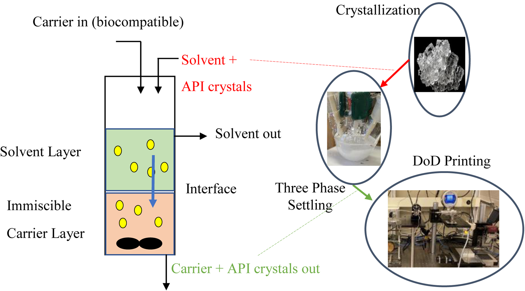
Figure 1 shows how the DoD printer and the TPS are envisioned to be integrated with the upstream crystallizer. API crystals generated in the crystallizer are to be continuously transferred to the printer carrier fluid in TPS. The resulting carrier-API crystal suspension is to be then printed via the DoD platform. The subsequent sections describe the working of TPS and DoD printer.
Figure 1.

Block diagram for the integrated crystallizer - TPS - DoD system. TPS acts as a continuous integration step connecting DoD with the upstream crystallizer step. Conventional intermediate processing steps like drying, blending and granulation face a variety of powder handling problems during small-scale continuous operations.
Drop on Demand (DoD) Printing
DoD is a type of inkjet printing where, as the name suggests, ink drops are printed “on demand” by the action of a printhead.20 In the context of pharmaceuticals, DoD is used to make drug products by printing an ink formulation (mixture of API and excipient carrier) onto a substrate like capsule, placebo tablet or edible film. Previous studies on pharmaceutical DoD have demonstrated is versatility in processing a variety of APIs and different types of formulations (solutions, melts, suspensions).21–23
Its working principle is as follows (Figure 2): A high precision positive displacement pump draws fixed volume packets of API formulation from a reservoir. This formulation is then pumped through a nozzle where the actuation of the pump triggers drop release. The released drops are printed onto the desired substrate to additively manufacture the drug product. Drug loading in the dosages is varied by changing the number of drops printed on the substrate while maintaining other process parameters constant, thereby, allowing for a high degree of ‘dose flexibility’.21,23,24 The DoD platform is fully automated and incorporates in-line sensors to monitor and log process parameters in real time.25 The tube sections of the printer are heated using Carbon Fiber Tubing developed by the Amy facility at Purdue. The reservoir is kept over a hotplate stirrer to ensure constant composition and temperature of the suspension being printed.
Figure 2.

Drop-on-demand printing - schematic (left) and apparatus (right). Reservoir shown here holds the ink formulation to be printed. A high precision positive displacement pump draws this ink and prints it through a nozzle in the form of drops. These drops then additively build the drug product on the substrate.
In this study, DoD is operated with suspension formulations, i.e., the ink being printed is a suspension of API crystals in a carrier fluid as it allows for manufacturing high drug loading dosages.26 Additionally, the carrier fluid used needs to be a safe inactive, i.e., it needs to be approved by the FDA for use in oral dosages. To generate this carrier-API crystal suspension continuously from the crystallizer’s outlet, a novel unit operation- Three-phase settling (TPS) is developed as a part of this study.
Three-Phase Settling (TPS)
Motivation for designing TPS
The idea for using settling in pharmaceutical manufacturing is not unique. Settlers are routinely used in many biopharmaceutical applications, particularly for separating and concentrating the cell suspension from the growth media.27 Settlers are also used as a continuous solid recycle step in mixed suspension mixed product removal (MSMPR) crystallizers where they serve to generate a concentrated recycle stream that can increase the yield of the crystallizer operation.28 Another common application for settlers is as mixer-settlers where the goal is to transfer dissolved solutes from one liquid phase into another.29
The main advantage of settling is that it is a very gentle unit operation ideal for delicate crystals and cells. Settlers, especially gravity settlers, have very low energy requirements and are easily amenable to continuous operation; thus, they are ideally suited for the present application. Note that the examples cited above involve settlers with only two phases.
The key idea underlying the TPS is to combine the operation of a gravity settler (which separates a solid from a liquid) and a mixer-settler (which transfers dissolved solutes from one liquid phase into another). This would thus yield a settler that can separate solid particles (API crystals) from one liquid phase (crystallization solvent) into another (biocompatible carrier). This is essentially a solvent switch operation, which is frequently encountered in pharmaceutical manufacturing and is usually carried out via two methods- distillation and filtration-drying. The first method, distillation, is unsuitable for the present application because separating the solvents at high temperatures would re-dissolve the synthesized crystals and alter crystal properties. The second approach- filtration, and drying involves the complexities of powder handling and suffers from the lack equipment for continuous operation at small scales. Moreover, if the filtration-drying steps can be eliminated, the overall process is simplified. Of course, the key requirement is the selection of a suitable pair of solvents.
Working Principle
The goal of the TPS is to transfer the crystals generated in the upstream crystallizer into a biocompatible carrier phase. The settler seeks to bring about this solvent switch by exploiting the density difference between the crystals and the solvent phases. This is illustrated in the schematic shown below (Figure 3). A suspension of crystals in the crystallization solvent, generated upstream, is fed continuously into the settler. The carrier phase is chosen such that it is immiscible with this incoming solvent. The heavier crystals settle through the solvent phase and into the carrier fluid. The carrier-crystal suspension is then continuously pumped out to the printer thereby completing the continuous integration between the DoD printer and the upstream crystallizer. The role of the impeller is to provide adequate agitation to the bottom phase to limit crystal segregation and inhibit crystal adhesion to vessel walls and the fluid interface.
Figure 3.
Working principle of the three-phase settler (TPS). The settler exploits the density differences between the solvents and the crystals. Higher density crystals are continuously transferred to the bottom carrier phase, this carrier-crystal suspension form the ink formulation to be printed.
Design space for three-phase settler
For TPS to function as intended its operating parameters need to lie within certain process bounds, which vary with the API-solvents system chosen. Therefore, as a part of this study, a design space has been developed for the TPS that contains all the process constraints and aids the user in selecting the appropriate operating conditions for a general API-solvents system. The conditions for formulating this space have been derived from the literature available on froth flotation,30 particle adhesion on fluid-fluid interfaces31 and particle suspensions.32
The operation of the settler can be broken down into three regions- top phase, interface and bottom phase with each region having process constrains. These constraints are summarized in Figure 4 and Table 1 and described as follows:
Figure 4.

Design space for three-phase settler: A) constraints in each region; B) graphical summary of constraints. To achieve continuous crystal separation, the settler must be operated within limits of the design space.
Table 1.
Legend of symbols for settler design space.
| Symbol | Expression |
|---|---|
Top phase:
The primary requirement for the three-phase settling to be feasible is that the API crystals should be denser than the crystallization solvent and carrier fluid so as to enable the heavier crystals to settle by gravity.
| #(1) |
Even after this constraint is satisfied, there is a lower bound on the terminal settling velocity of the particle in the top phase, i.e.,
| #(2) |
This critical threshold depends on the geometric features and residence time of the settler
| #(3) |
( are height and residence time of the top phase respectively). Essentially this condition implies that the settling velocity in the top phase must be fast enough so as to avoid crystal loss in the solvent outlet. If the settling velocity is too low then crystals will tend to get carried out with the solvent rather than settling into the bottom phase, resulting in much lower yield. The parameter ‘10’ is empirically suggested, higher values can be used based on acceptable crystal loss limits. There are many correlations available for computing terminal settling velocity of particles33 in quiescent and stirred media.32
Interface:
The second region is the interface between the two phases, this region can exhibit an interesting adhesion behavior for some API-solvent systems. In some cases (especially for crystals in the micron size range) an interplay of crystal-solvent and solvent-solvent surface tension effects can cause retention of the API crystals at the solvent-carrier interface. This occurs when the presence of particles at the interface leads to an overall reduction in surface energy of the system.34 Occurrence of crystal adhesion can be predicted by computing the Bond number (Bo) of particles at the interface;31 the Bond number is a ratio of the gravity force and the upward acting surface tension force.
| #(4) |
In the above equation are the particle and bottom phase fluid density respectively, is the diameter of the particle, is the acceleration due to gravity and is the surface tension between the particle and the bottom phase fluid. If Bo <<1 then the surface tension forces dominate and the particle remains attached to the interface, otherwise, the particle settles.
In case particle adhesion does occur in the system, settling can be brought about by providing enough energy to overcome the surface forces. The energy of adhesion of a particle attached to a fluid-fluid interface is given by the following equation:31
| #(5) |
Here is the interfacial tension between the two fluids and is the three-phase contact angle:
| #(6) |
(the index 1 indicates the top phase and 2 indicates the bottom phase). The energy to overcome this is provided via the impeller as kinetic energy. There are many ways to determine this kinetic energy imparted to the particle, a simple approach is to estimate the kinetic energy from the impeller diameter and agitation rate:30
| #(7) |
In the experiments carried out in this study, particle detachment was observed for cases when kinetic energy imparted by the impeller was greater than the adhesion energy (). This provides a lower limit for agitation rate as it must be high enough to cause particle detachment.
| #(8) |
The upper limit on agitation rate is given by the rate at which the solvent-carrier phase separation is broken. Beyond a critical threshold, the top phase gets dispersed into the bottom phase, which is highly undesirable as the API formulation cannot contain solvents impurities, which can be detrimental to the patients. Phase entrainment happens when the depression in the top phase upon agitation reaches the impeller. For unbaffled tanks, this agitation rate is given as follows:
and is obtained by solving the equation:
| #(9) |
Here, vortex depth is set to be the impeller submergence, are the Froude number, Reynolds number, impeller submergence height and impeller diameter of the system, respectively. The symbols denote correlation parameters, which are set to be equal to 12.9, 0.11, 0.17 and −4.27, respectively.35
Bottom Phase:
The bottom phase condition ensures that stir speed be sufficient so as to ensure complete suspension of crystals in the bottom phase . Correlations for are available for baffled36 and unbaffled systems.37
To summarize the above discussion, the design space gives feasibility limits for two critical parameters: the top phase settling velocity (material parameter) and the Impeller speed (operating parameter). The lower bound for is to ensure quick settling in the top phase, bounds for provide values for which particle detachment occurs and values at which phase separation is lost. If there is no particle adhesion, the lower bound is given by the rate to ‘just suspend’ the bottom phase (illustrated in Figure 4B).
Apparatus:
The settler is comprised of a three necked round bottomed flask (25 mL) purchased from Synthware. Stirring is provided by clamping the flask over a stirplate. Flows through the settler are ordered as follows, the suspension from the crystallizer is fed into the flask from the center. Outlet tubes are held such that the product tube is completely immersed in the lower fluid phase and the solvent tube is immersed in the upper phase. The solvent flows are set using peristaltic pumps (Masterflex 77200–50, Cole Parmer) and syringe pumps (Fisherbrand single syring pump).
Three-phase settler model
To predict the concentration of the carrier-crystal suspension generated in the settler, a first principles model is developed. A few assumptions are made about the operation of the settler: the first assumption is that the settling velocity of particles is much higher in the top phase than the bottom phase. This allows for neglecting particle transfer dynamics in the top phase as the high settling velocity would make residence time in the top phase negligible. The second assumption is that there is no crystal accumulation in the settler, i.e., there is no crystal adhesion to the vessel walls or interface. The presence of an impeller in the settler ensures that this assumption is met as the agitation created would act to dislodge any adhered crystals. The final assumption is that the suspension in the bottom phase is well mixed, this assumption can be made as the volume of suspension being agitated is low (~ 5–10 mL) which allows for ideal mixing.
The equation used for predicting the carrier-crystal concentration generated is given below, this equation resembles that of concentration evolution in an ideal stirred tank. Here, is the crystal concentration in the suspension entering the crystallizer, and are the feed and carrier flow rates, respectively, and is the residence time of the particles in the bottom phase.
| #(10) |
Real time monitoring of drug loading
As discussed earlier, real time monitoring of product CQAs is necessary to avoid destructive tests on the manufactured dosages. Drug loading in the printed dosages is an important CQA as it needs to be meet the amount of API required for the desired therapeutic effect. To monitor drug loading in real time two PAT tools- an FBRM probe and a load cell were incorporated into the DoD platform. The working principle of the former are as follows (Figure 10): the FBRM probe is used to measure concentration of the suspension being printed. The particle counts/second measured by the probe is correlated with suspension concentration.38,39 The role of the load cell is to measure the weight of the capsule as it is filled with the printed drops. These two measurements are combined to monitor the drug loading being printed into the capsule in real time.
Figure 10.
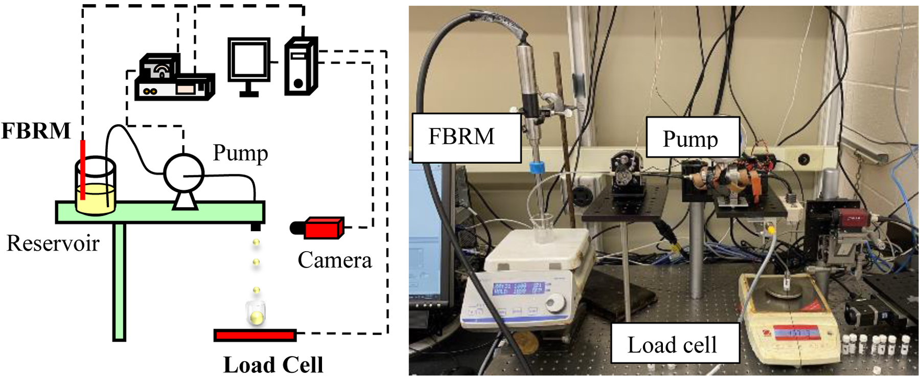
Real-time monitoring of drug loading- schematic (left) and apparatus (right).
ParticleTrack G400, Mettler Toledo is the FBRM probe used to measure suspension concentration in the DoD printer’s reservoir, Ohaus PA224 precision balance is used as the load cell to measure capsule weight.
Three-phase settling of celecoxib
The operation of the proposed manufacturing scheme (Figure 1) is investigated via two case studies. The first case study aims to demonstrate the standalone operation of the Three Phase Settler using the API celecoxib. Celecoxib is a nonsteroidal anti-inflammatory drug commonly used as pain medication. The goal here is to test whether the settler can transfer celecoxib from the solvent phase to the carrier phase continuously using operating conditions which satisfy the design space.
This case study also seeks to demonstrate another important function of the settler- concentration control of print stream. Namely, this study endeavors to investigate whether manipulating stream flows coming into the settler can allow for controlling the concentration of the carrier-crystal suspension generated. This is important since there is a limit on the size of capsules that can be consumed by patients, thus the drug loading cannot be increased indefinitely by printing more drops into bigger capsules. This implies that to increase the range of drug loading in capsules crystal concentration in the suspension being printed must be controlled.
Continuous integrated manufacturing of lomustine
The second case study seeks to demonstrate the operation of the integrated system (crystallizer-TPS-DOD). The API used for this is lomustine, an anticancer drug used in treating brain tumors. It has seen an enormous price increase in the recent years (~2000%) causing many hardships for its patients. Previous studies have developed a continuous reactor40 and crystallizer41,42 for its synthesis. The goal of this case study is to continuously process the outlet of the crystallizer to generate lomustine suspension in a biocompatible carrier. This suspension is then to be printed continuously into capsules to manufacture lomustine dosages. The dissolution profile of the dosages is then investigated to assess whether it matches that of existing commercial product.
Chemicals
Two APIs are used in the experiments- celecoxib (ChemShuttle, Union City CA) and lomustine (synthesized in house following the procedure described by Jaman et al.40). Two solvent phases are used for experiments with the settler, the upper fluid phase used is heptane (Fisher chemicals) and the lower fluid phase is Polyethylene glycol 200 (PEG) (TCI America). When used with celecoxib, the PEG phase is diluted with deionized water (25% by wt) to limit dissolution of the API. PEG is chosen as the carrier as it is an FDA approved inactive and is completely immiscible with the crystallization solvent being used (heptane).
HPLC:
Concentrations of the streams flowing in and out of the settler are analyzed using an Agilent 1100 series HPLC system. Samples from each stream are collected at different timepoints during the operation then diluted with HPLC grade methanol (Fisher). Concentrations are determined using peak areas at 260 nm (lomustine) and 280 nm (celecoxib) obtained from the HPLC.
Dissolution test:
A Distek 2100c dissolution system is used for analyzing the dissolution profiles of the manufactured dosages. Each dosage was dissolved in a 6.8 pH buffer prepared with Sodium Lauryl Sulphate (10 g/L), Disodium phosphate (3.47 g/L) and Monopotassium phosphate (3.47 g/L) dissolved in water. The apparatus was operated at a temperature of 37 °C and an agitation rate of 75 rpm. Solvent samples are extracted at specified times and analyzed using an offline UV spectrophotometer (peak- 260 nm).
Results and Discussion
Continuous three-phase settling of celecoxib
The apparatus used for this experiment is shown in Figure 5A, the goal is to assess whether the settler can separate celecoxib crystals from the solvent phase to the carrier phase. The feed to the settler is a suspension of celecoxib crystals in heptane which is held in a feed tank at a constant agitation rate of 200 rpm. The suspension from this tank is fed into the settler at a constant rate (1 ml/min). The bottom phase used in the settler (PEG + water) is also fed at the same rate. Inside the settler, outlets from the PEG and heptane phases are ordered as shown in Figure 5 and continuously withdrawn. Samples are periodically collected from each stream and analyzed with the HPLC to determine API concentration.
Figure 5.

Experimental setup used for the two case studies. A] Setup for celecoxib case study. Celecoxib- heptane suspension is transferred from the feed tank into the settler. Carrier phase inlet is varied to study the concentration control capability of TPS; B] Setup for lomustine case study. Crystallizer generates a suspension of lomustine crystals in heptane continuously. The settler transfers these crystals into the carrier phase and thus creates the ink formulation for printing.
The operating conditions used for the settler are summarized in Table 3. Mean particle size of the celecoxib crystals was Bond number of the heptane–celecoxib–PEG + water system was computed to be and particle adhesion was observed at the interface. Critical settling velocity in the top phase was computed to be and was found to be equal to ; thus . The just suspended agitation rate was found to be and the critical impeller speed at which phase separation was lost was calculated to be . For it was found that was greater than . Thus, the bounds on impeller rate are , the operating value for was chosen to be . Note that in a few cases the correlations used were outside of their reported bounds: this was done as no other suitable models were found for the present system.
Table 3.
Summary of operating conditions for Three phase settling of celecoxib.
| Bo | ||||||
|---|---|---|---|---|---|---|
| 100 | 1.322 × 10⁻³ | 2.358 × 10⁻⁴ | 1.038 × 10⁻² | 10.497 | 1588.35 | N = 1100rpm |
The results of the experiment (Figure 6A) show that the settler is able to transfer celecoxib crystals into the PEG phase successfully and there is very little crystal loss with the outgoing heptane. The settler was initially filled with 8 ml of each phase, thus the crystal concentration in PEG phase gradually builds up to the steady state value, this increase is captured well in the experimental profile. Predictions of the proposed settler model are also seen to fit the experimental profiles reasonably well. Deviations from model predictions are attributed primarily to the aggregation tendency of celecoxib crystals in heptane. It was observed that celecoxib crystals tended to form aggregates in heptane while being stirred in the feed tank and that many of these aggregates propagated into the feed stream of the settler. The presence of crystal aggregates caused fluctuations in the feed concentrations recorded which in turn created some variance in the model predictions.
Figure 6.

Three-phase settling of celecoxib. A] Demonstration of standalone operation. Experimental datapoints and model predictions shown; B and C demonstrate concentration control capability of TPS; B] Higher carrier flow rate- product stream generated is lower in concentration; C] Lower carrier flow rate- product stream generated is more concentrated than feed. This will be useful in manufacturing high drug loading dosages.
The results of the concentration control experiment are shown in Figures 6B and 6C. In this experiment the feed flow rate is held constant and the carrier flow rate is changed to 0.5 ml/min in one scenario and 1.5 ml/min in another. The results show that there is an inverse relationship between the carrier flow rate and the steady state crystal concentration. Decreasing PEG flow rate by half nearly doubled the particle concentration and increasing flow by 1.5 times reduced concentration by the same factor. In summary, the results shown in Figure 6 show that the settler can be used as a pre-printing concentration adjustment step thereby enabling the DoD platform to produce dosages with a wide range of drug loadings.
Another important consideration in the process is the amount of solvent carryover with the carrier-crystal suspension outlet of the settler. Crystallization solvents can be toxic and need to be removed from the carrier-crystal suspension generated. The settler relies on carrier fluid selection which assures low solubility of solvent in the carrier phase. In addition to this design requirement, the operating conditions must also be selected to minimize carryover, As long as the agitation rate is not higher than the critical value (, there will be no additional solvent entrainment and the solvent impurity in the print stream would be within the acceptable limit (<0.25 wt% in final dosage).
Continuous integrated manufacturing of lomustine
Integrated crystallizer-settler operation
The goal of this experiment is to test the integrated operation, of the linked crystallizer-TPS system. The setup used for the experiment is shown in the Figure 5B, the crystallizer shown is described in the work of Mackey et al.41,42 The outlet stream of the crystallizer, a suspension of lomustine crystals in heptane, is fed into the setter which continuously transfers the crystals to the carrier phase (PEG). The graphs given in (Figure 7A and 7B) show the evolution of stream concentrations out of the settler. The lomustine-PEG suspension concentration is well predicted by the model in both cases.
Figure 7.

Lomustine case study integrated crystallizer settler operation: A) Concentration evolution for equal carrier and feed flow rates (1 ml/min); B) Concentration evolution for reduced carrier flow rate (0.5 ml/min); C] Predicted steady state values for equal (1 ml/min) and reduced (0.5 ml/min) carrier flow rates
The experiment was carried out for a feed flow rate of 1ml/min and two carrier phase flow rates 1 ml/min and 0.5 ml/min. It is evident that the API concentration in the product stream was not high enough for the case when PEG and feed flow rates were equal and so PEG flow rate was reduced to generate a more concentrated suspension for printing. It can be observed that there is a significant concentration of lomustine that is left in the heptane phase (‘Top’). This lomustine is the dissolved API that did not crystallize out in the crystallizer. The net feed transferred into the PEG phase is thus taken to be the difference of feed stream concentration and an average of the heptane phase concentration. The graphs shown in figures 7A and 7B thus demonstrate a successful integration of the upstream crystallizer and settler for this case study.
The profiles shown here cover the dynamic start-up period to the initiation of steady state but do not include extended periods of steady state operation, this is because the crystallizer used had some clogging problems during longer runs. These clogging problems are undergoing further investigation as a separate line of inquiry. Steady state values for these experiments have been predicted using the model developed, under the assumption that the feed stream concentration remains the same as the last experimental measurement (Figure 7C).
Drop on demand printing and dissolution testing
The lomustine-PEG suspension generated through the settler is next used for printing. Prior to manufacturing the dosages, it needs to be ensured that the formulation can be solidified as having the dosage in solid form increases its long-term stability and ease of transport. In the present case study, dosages are solidified by increasing the melting point of PEG-lomustine suspension prior to printing. Polyethylene glycol 4000 (5 wt%) and Polyethylene glycol 600 (5 wt%) are added to the suspension in the reservoir, this blending serves to broaden the molecular weight distribution of polyethylene glycol in suspension which in turn increases its melting point.
The modified suspension is then printed into gelatin capsules where it then self-solidifies at room temperature. Images shown in figure 8 are of the final lomustine drug product. After the suspension is printed into the capsule, it is observed that the formulation solidifies in approximately 10 minutes into a gel-like solid. Lomustine crystals remain embedded in this matrix and the capsule contents are seen to remain undisturbed even after vigorous shaking by hand.
Figure 8.

Printed lomustine drug product. The PEG carrier phase solidifies after printing in approximately 10 minutes. The formulation then attains the form of a gel-like solid with the lomustine crystals embedded in it. The contents of the drug product maintained their form even after shaking by hand.
Dissolution profile of the printed dosages is compared with the existing commercial product. In this test, one unit of commercial lomustine capsule (Gleostine, 10 mg, NextSource Pharmaceuticals) and six units of printed lomustine capsules are dissolved in the apparatus described above following USP guidelines. For a 10 mg target dose, after 30 minutes of dissolution, the six printed dosages contained an average of 9.44 mg of lomustine with a standard deviation of 0.31 and the commercial capsule contained 10.44 mg. The dissolution profiles obtained (Figure 9) are seen to match closely. The printed dosages seem have a slightly lower amount of drug compared to the commercial product, but this can be rectified by printing a few more drops of PEG-lomustine suspension in each capsule.
Figure 9.

Dissolution profile comparison between printed and commercial lomustine capsule. The profiles match each other closely, the printed dosages are seen to have slightly lower amount of drug, this can be rectified by printing a few more drops of the formulation.
Real time monitoring of suspension concentration
For this experiment the celecoxib – PEG + water suspension discussed in the first case study is used as ink formulation for printing. The apparatus used for this experiment is shown in figure 10, as described earlier the FBRM is used to obtain particle concentration in real time and the load cell monitors capsule weight. For this experiment, first a calibration curve is constructed to correlate particle concentration to the average counts read by the FBRM. A high R2 value indicated a good relationship between particle concentration and counts. After this a celecoxib – PEG + water suspension of unknown concentration is prepared. Specifically, 30 drops of this unknown concentration formulation are printed into the substrate During the printing, the FBRM-load cell system is used to monitor drug loading being in the substrate in real time. Drug loading prediction by these PAT tools is compared with independent measurements made on the substrate by analyzing it on HPLC.
Results of this analysis (Table 5) show that the celecoxib amount in the substrate is well predicted by the FBRM-load cell system in real time with the average prediction error being under 4%. The deviations from PAT predictions primarily arise because of the broad size distribution of celecoxib crystals used for making the dosages. The wide size distribution leads to variation in concentration of each drop printed which in turn causes differences in celecoxib amounts. In a manufacturing setting, this error can be further reduced by having a tighter control on the crystallization step to generate crystals with a narrow size distribution.
Table 5.
Real time monitoring of drug loading.
| Drug Loading (HPLC) (mg) | Drug Loading (FBRM-Load cell) (mg) | % error |
|---|---|---|
| 14.08 | 13.96 | 0.85 |
| 12.90 | 13.67 | 5.97 |
| 12.83 | 13.11 | 2.17 |
| 12.81 | 13.16 | 2.72 |
| 13.24 | 12.37 | 6.57 |
| Avg Error = 3.66 |
Conclusions
In conclusion, this study introduces a novel unit operation, TPS, to continuously integrate a 3DP platform (DoD) with the crystallization operation of API synthesis. Accomplishing this integration marks an important milestone in envisioning the development of 3DP and continuous manufacturing together.
The celecoxib case study demonstrates the standalone operation of TPS and experimentally validates its concentration control capability. The lomustine case study experimentally demonstrates the crystallizer – TPS – DoD integration and shows continuous manufacturing of lomustine drug product. A dissolution test is performed on the printed dosages following regulatory guidelines, and its dissolution profile is seen to match that of the existing commercial product. To ensure that each manufactured dosage contains the specified dose amount, a FBRM-load cell system is incorporated in the printer to monitor drug loading in the dosages in real time.
The results shown in this study demonstrates an important step towards building a fully autonomous E2EC mini plant. Development of such mini plants will be an important prerequisite if pharmaceutical manufacturing is to transition away from the current mass production scheme.
Supplementary Material
Table 2.
Material summary for the two case studies.
| Top Phase | Bottom Phase | API | |
|---|---|---|---|
| Three-phase settling of celecoxib | Heptane | PEG + Water | celecoxib |
| Continuous integrated manufacturing of lomustine | Heptane | PEG | lomustine |
Table 4.
Operating conditions for Continuous integrated manufacturing of lomustine.
| Bo | ||||||
|---|---|---|---|---|---|---|
| 50 | 2.25 × 10⁻⁴ | 2.358 × 10⁻⁴ | 2.595 × 10⁻³ | 3.042 | 1652.91 | N = 1200rpm |
Acknowledgements
Funding for this publication was made possible, in part, by the Food & Drug Administration through grant (U01FD006738). Views expressed in written materials or publications and by speakers and moderators do not necessarily reflect the official policies of the Department of Health and Human Services; nor does any mention of trade names, commercial practices, or organization imply endorsement by the United States Government.
The authors would also like to express gratitude to Jaron Mackey for helping with the crystallizer-settler integration experiments and to Shumaiya Ferdoush for assisting with the dissolution tests.
References
- 1.Innovations in Pharmaceutical Manufacturing on the Horizon. National Academies Press; 2021. doi: 10.17226/26009 [DOI] [PubMed] [Google Scholar]
- 2.Lee SL, O’Connor TF, Yang X, et al. Modernizing Pharmaceutical Manufacturing: from Batch to Continuous Production. Journal of Pharmaceutical Innovation. 2015;10(3). doi: 10.1007/s12247-015-9215-8 [DOI] [Google Scholar]
- 3.Badman C, Coone L, Florenc A, et al. Why We Need Continuous Pharmaceutical Manufacturing and How to Make It Happen. Journal of Pharmaceutical Sciences. 2019;108(11). doi: 10.1016/j.xphs.2019.07.016 [DOI] [PubMed] [Google Scholar]
- 4.Mascia S, Heider PL, Zhang H, et al. End-to-end continuous manufacturing of pharmaceuticals: Integrated synthesis, purification, and final dosage formation. Angewandte Chemie - International Edition. 2013;52(47):12359–12363. doi: 10.1002/anie.201305429 [DOI] [PubMed] [Google Scholar]
- 5.Srai JS, Badman C, Krumme M, Futran M, Johnston C. Future supply chains enabled by continuous processing-opportunities and challenges May 20–21, 2014 continuous manufacturing symposium. Journal of Pharmaceutical Sciences. 2015;104(3). doi: 10.1002/jps.24343 [DOI] [PubMed] [Google Scholar]
- 6.Srai JS, Kumar M, Graham G, et al. Distributed manufacturing: scope, challenges and opportunities. International Journal of Production Research. 2016;54(23). doi: 10.1080/00207543.2016.1192302 [DOI] [Google Scholar]
- 7.Adamo A, Beingessner RL, Behnam M, et al. On-demand continuous-flow production of pharmaceuticals in a compact, reconfigurable system. Science. 2016;352(6281). doi: 10.1126/science.aaf1337 [DOI] [PubMed] [Google Scholar]
- 8.Zhang P, Weeranoppanant N, Thomas DA, et al. Advanced Continuous Flow Platform for On-Demand Pharmaceutical Manufacturing. Chemistry - A European Journal. 2018;24(11). doi: 10.1002/chem.201706004 [DOI] [PubMed] [Google Scholar]
- 9.Reizman BJ, Cole KP, Hess M, et al. Small-Volume Continuous Manufacturing of Merestinib. Part 2. Technology Transfer and cGMP Manufacturing. Organic Process Research and Development. 2019;23(5). doi: 10.1021/acs.oprd.8b00442 [DOI] [Google Scholar]
- 10.Cole KP, Reizman BJ, Hess M, et al. Small-Volume Continuous Manufacturing of Merestinib. Part 1. Process Development and Demonstration. Organic Process Research and Development. 2019;23(5). doi: 10.1021/acs.oprd.8b00441 [DOI] [Google Scholar]
- 11.Alomari M, Mohamed FH, Basit AW, Gaisford S. Personalised dosing: Printing a dose of one’s own medicine. International Journal of Pharmaceutics. 2015;494(2). doi: 10.1016/j.ijpharm.2014.12.006 [DOI] [PubMed] [Google Scholar]
- 12.Daly R, Harrington TS, Martin GD, Hutchings IM. Inkjet printing for pharmaceutics - A review of research and manufacturing. International Journal of Pharmaceutics. 2015;494(2). doi: 10.1016/j.ijpharm.2015.03.017 [DOI] [PubMed] [Google Scholar]
- 13.Jamróz W, Szafraniec J, Kurek M, Jachowicz R. 3D Printing in Pharmaceutical and Medical Applications – Recent Achievements and Challenges. Pharmaceutical Research. 2018;35(9). doi: 10.1007/s11095-018-2454-x [DOI] [PMC free article] [PubMed] [Google Scholar]
- 14.Hsiao WK, Lorber B, Reitsamer H, Khinast J. 3D printing of oral drugs: a new reality or hype? Expert Opinion on Drug Delivery. 2018;15(1). doi: 10.1080/17425247.2017.1371698 [DOI] [PubMed] [Google Scholar]
- 15.Melocchi A, Loreti G, del Curto MD, Maroni A, Gazzaniga A, Zema L. Evaluation of hot-melt extrusion and injection molding for continuous manufacturing of immediate-release tablets. Journal of Pharmaceutical Sciences. 2015;104(6). doi: 10.1002/jps.24419 [DOI] [PubMed] [Google Scholar]
- 16.Puri V, Brancazio D, Desai PM, et al. Development of Maltodextrin-Based Immediate-Release Tablets Using an Integrated Twin-Screw Hot-Melt Extrusion and Injection-Molding Continuous Manufacturing Process. Journal of Pharmaceutical Sciences. 2017;106(11). doi: 10.1016/j.xphs.2017.06.020 [DOI] [PubMed] [Google Scholar]
- 17.Byrn S, Futran M, Thomas H, et al. Achieving continuous manufacturing for final dosage formation: Challenges and how to meet them May 20–21, 2014 continuous manufacturing symposium. Journal of Pharmaceutical Sciences. 2015;104(3). doi: 10.1002/jps.24247 [DOI] [PubMed] [Google Scholar]
- 18.Yu DG, Zhu LM, Branford-White CJ, Yang XL. Three-dimensional printing in pharmaceutics: Promises and problems. Journal of Pharmaceutical Sciences. 2008;97(9). doi: 10.1002/jps.21284 [DOI] [PubMed] [Google Scholar]
- 19.Muzzio FJ, Shinbrot T, Glasser BJ. Powder technology in the pharmaceutical industry: The need to catch up fast. Powder Technology. 2002;124(1–2). doi: 10.1016/S0032-5910(01)00482-X [DOI] [Google Scholar]
- 20.Basaran OA, Gao H, Bhat PP. Nonstandard inkjets. Annual Review of Fluid Mechanics. 2013;45. doi: 10.1146/annurev-fluid-120710-101148 [DOI] [Google Scholar]
- 21.Radcliffe AJ, Hilden JL, Nagy ZK, Reklaitis G v. Dropwise Additive Manufacturing of Pharmaceutical Products Using Particle Suspensions. Journal of Pharmaceutical Sciences. 2019;108(2). doi: 10.1016/j.xphs.2018.09.030 [DOI] [PubMed] [Google Scholar]
- 22.Içten E, Giridhar A, Nagy ZK, Reklaitis GV. Drop-on-Demand System for Manufacturing of Melt-based Solid Oral Dosage: Effect of Critical Process Parameters on Product Quality. AAPS PharmSciTech. 2016;17(2). doi: 10.1208/s12249-015-0348-3 [DOI] [PMC free article] [PubMed] [Google Scholar]
- 23.Hirshfield L, Giridhar A, Taylor LS, Harris MT, Reklaitis GV. Dropwise additive manufacturing of pharmaceutical products for solvent-based dosage forms. Journal of Pharmaceutical Sciences. 2014;103(2). doi: 10.1002/jps.23803 [DOI] [PubMed] [Google Scholar]
- 24.Içten E, Giridhar A, Taylor LS, Nagy ZK, Reklaitis GV. Dropwise additive manufacturing of pharmaceutical products for melt-based dosage forms. Journal of Pharmaceutical Sciences. 2015;104(5). doi: 10.1002/jps.24367 [DOI] [PubMed] [Google Scholar]
- 25.Içten E, Joglekar G, Wallace C, et al. Knowledge Provenance Management System for a Dropwise Additive Manufacturing System for Pharmaceutical Products. Industrial and Engineering Chemistry Research. 2016;55(36). doi: 10.1021/acs.iecr.6b01042 [DOI] [Google Scholar]
- 26.Radcliffe AJ, Reklaitis GV. Dropwise Additive Manufacturing using Particulate Suspensions: Feasible Operating Space and Throughput Rates. In: Computer Aided Chemical Engineering. Vol 40. ; 2017. doi: 10.1016/B978-0-444-63965-3.50203-8 [DOI] [Google Scholar]
- 27.Shen Y, Yanagimachi K. CFD-aided cell settler design optimization and scale-up: Effect of geometric design and operational variables on separation performance. Biotechnology Progress. 2011;27(5). doi: 10.1002/btpr.636 [DOI] [PubMed] [Google Scholar]
- 28.Li J, Trout BL, Myerson AS. Multistage Continuous Mixed-Suspension, Mixed-Product Removal (MSMPR) Crystallization with Solids Recycle. Organic Process Research and Development. 2016;20(2). doi: 10.1021/acs.oprd.5b00306 [DOI] [Google Scholar]
- 29.Kumar S, Kumar B, Sampath M, Sivakumar D, Kamachi Mudali U, Natarajan R. Development of a micro-mixer-settler for nuclear solvent extraction. Journal of Radioanalytical and Nuclear Chemistry. 2012;291(3). doi: 10.1007/s10967-011-1447-6 [DOI] [Google Scholar]
- 30.Sherrell IM. Development of a Flotation Rate Equation from First Principles under Turbulent Flow Conditions. Mining and Minerals Engineering. Published online 2004. [Google Scholar]
- 31.Davies GB, Krüger T, Coveney PV., Harting J Detachment energies of spheroidal particles from fluid-fluid interfaces. Journal of Chemical Physics. 2014;141(15). doi: 10.1063/1.4898071 [DOI] [PubMed] [Google Scholar]
- 32.Nocentini M, Magelli F. Solid distribution in slurry reactors stirred with multiple impellers: continuous flow systems. Published online 1992. doi: 10.1007/978-94-015-7973-5_9 [DOI] [Google Scholar]
- 33.Haider A, Levenspiel O. Drag coefficient and terminal velocity of spherical and nonspherical particles. Powder Technology. 1989;58(1). doi: 10.1016/0032-5910(89)80008-7 [DOI] [Google Scholar]
- 34.Garbin V Colloidal particles: Surfactants with a difference. Physics Today. 2013;66(10). doi: 10.1063/PT.3.2158 [DOI] [Google Scholar]
- 35.Deshpande SS, Kar KK, Walker J, Pressler J, Su W. An experimental and computational investigation of vortex formation in an unbaffled stirred tank. Chemical Engineering Science. 2017;168. doi: 10.1016/j.ces.2017.04.002 [DOI] [Google Scholar]
- 36.Raghava Rao KSMS, Rewatkar VB, Joshi JB. Critical impeller speed for solid suspension in mechanically agitated contactors. AIChE Journal. 1988;34(8). doi: 10.1002/aic.690340811 [DOI] [Google Scholar]
- 37.Mixing Nagata S.. Principles and applications. Published online 1975.
- 38.Dave K, Luner PE, Forness C, Baker D, Jankovsky C, Chen S. Feasibility of Focused Beam Reflectance Measurement (FBRM) for Analysis of Pharmaceutical Suspensions in Preclinical Development. AAPS PharmSciTech. 2018;19(1). doi: 10.1208/s12249-017-0819-9 [DOI] [PubMed] [Google Scholar]
- 39.Stelzer T, Wong SY, Chen J, Myerson AS. Evaluation of PAT Methods for Potential Application in Small-Scale, Multipurpose Pharmaceutical Manufacturing Platforms. Organic Process Research and Development. 2016;20(8). doi: 10.1021/acs.oprd.6b00129 [DOI] [Google Scholar]
- 40.Jaman Z, Sobreira TJP, Mufti A, Ferreira CR, Cooks RG, Thompson DH. Rapid On-Demand Synthesis of Lomustine under Continuous Flow Conditions. Organic Process Research and Development. 2019;23(3). doi: 10.1021/acs.oprd.8b00387 [DOI] [Google Scholar]
- 41.Mackey J, Mufti A, Leec SL, et al. Process Design and Development of a Small Scale Hybrid Manufacturing System for the Cancer Drug Lomustine. Virtual AiChE Annual Meeting AIChE. Published online 2020. Accessed March 29, 2021. https://aiche.confex.com/aiche/2020/meetingapp.cgi/Paper/608189 [Google Scholar]
- 42.Mackey J, Mufti A, Harris A, et al. Continuous process design and development for the cancer drug Lomustine (in preparation). in preparation.
Associated Data
This section collects any data citations, data availability statements, or supplementary materials included in this article.