



Abstract
Transitional metal oxides (TMOs) with ultra‐high specific surface areas (SSAs), large pore volume, and tailored exposed facets appeal to significant interests in heterogeneous catalysis. Nevertheless, synthesizing the metal oxides with all the above features is challenging. Herein, the so‐called seeds/NaCl‐mediated growth method is successfully developed based on a bottom‐up route. First, the (Brunauer‐Emmett‐Teller) BET SSAs of TMOs prepared with this method are significantly higher, where the BET SSAs of CeO2, SnO2, Nb2O5, Fe3O4, Mn3O4, Mg(OH)2, and ZrO2 reached 187, 275, 518, 212, 147, 186, and 332 m2 g−1, respectively. Second, these TMOs exhibit unique mesoporous structures, generated mainly by the aggregation of rod‐like or other aspherical primary nanoparticles. More importantly, no environmental‐unfriendly organic surfactants or expensive metal alkoxides are involved in this method. Therefore, the entire synthesis protocol fully fitted the “green synthesis” definition, and the corresponding TMOs prepares displayed excellent catalytic performance.
Keywords: mechanochemistry, rod‐like nanoparticles, salt template, seeds‐mediated growth method, transitional metal oxides
Transitional metal oxides (TMOs) with ultra‐high specific surface areas (SSAs), large pore volume, and tailored exposed facets appeal to significant interests in heterogeneous catalysis. In this study, a green seeds/NaCl‐mediated growth method is successfully developed, where no surfactants or metal‐organic precursors are involved. Importantly, the prepared TMOs exhibit significantly improves SSAs and optimized mesoporous structure.

1. Introduction
Pore engineering of transitional metal oxides (TMOs) with the tailored pore structure appealed to significant attention in heterogeneous catalysis.[ 1 , 2 , 3 ] In the state‐of‐art synthesis of porous TMOs (e.g., the sol‐gel methods,[ 4 , 5 ] the combustion methods,[ 6 , 7 ] surfactant‐assisted precipitation,[ 8 ] and the template‐free self‐assembly method[ 9 , 10 , 11 ]), the pores inside TMOs mainly resulted from the stacking of primary metal oxide nanoparticles. Among them, due to an uneven particle size distribution of primary nanoparticles, the pore structures formed by primary particle accumulation are always disordered. Moreover, these primary nanoparticles often have a spherical morphology, which is of less interest in catalysis. Because the exposed {110} or {100} planes in nanorods were sometimes more catalytic active than {111} planes of nanoparticles. Typically, hard‐templating or hydrothermal methods were used to construct mesoporous TMOs with faceted primary nanoparticles.[ 12 , 13 ] However, the BET‐specific surface areas (SSAs) of TMOs prepared by these methods were often limited (e.g., Co3O4: 62 m2 g−1,[ 14 ] CeO2: 121 m2 g−1,[ 15 ] and NiO: 94 m2 g−1.[ 16 ]) In addition, these protocols often required time‐consuming steps (e.g., several days).[ 17 , 18 , 19 ] To date, a synthetic principle for porous TMOs with non‐spherical primary nanoparticles should conform to low‐cost standards, environmental protection, simple process, and easy amplification.
As to the synthesis of metal oxide catalysts, the precipitation process was one of the most efficient unit operations. In view that the Ksp of transitional metal cations were normally <10−14 (e.g., Ksp‐α‐Co(OH)2, Cu(OH)2, and Al(OH)3 = 1.09 × 10⁻¹⁵, 2.2 × 10⁻²⁰, and 1.3 × 10⁻³³ respectively),[ 20 ] a high supersaturation of metal hydroxide in the solution was usually achieved. Besides, the distribution of the supersaturation ratio in the vessel during precipitation was often uneven with the location and time.[ 21 ] These factors led to a quick and variable nucleation rate. Therefore, the TMO products by the precipitation were always poorly controlled. In contrast to the uncontrollable nucleation under the wet‐chemistry precipitation process, the solid‐state nucleation induced by mechanochemical activation could be carefully tuned by adjusting the grinding parameters: ball‐filling ratio, ball‐to‐powder mass ratio, and grinding time.[ 22 , 23 ] In addition, in the synthesis of colloidal nanoparticles, the secondary growth of initial seeds provided a great chance to produce a finer structure with a more uniform size and regular morphology.[ 24 , 25 , 26 ] Inspired by the seed‐mediated method, the effective separation of nucleation and growth might be created by the combination of solvent chemistry and mechanochemistry.[ 27 ] The whole synthetic process was designed in two steps: TMO seed synthesis by the solid‐state ball milling process and subsequent seed growth under a solution environment. Therefore, it would be interesting to figure out whether combining solid‐state mechanochemistry and wet chemistry could control the structure of TMOs.
Different from the previous literature that TMOs were only produced by solid‐state precipitation,[ 22 , 28 ] in this paper we established a so‐called seed/NaCl‐mediated growth method consisting of two steps: the first step of solid‐state precipitation and the second step of hydrolysis or precipitation in solution. Specifically, the nanoparticles supported on NaCl after the solid‐state precipitation served as seeds. Moreover, the disappearance of the TMO‐NaCl interface during solution growth exposed an unsaturated crystal surface that was originally stabilized by NaCl. These highly reactive crystal surfaces with unsaturated coordination provided possible reaction sites for subsequent seed growth. Interestingly, after the secondary growth, a series of mesoporous metal oxides with ultra‐high SSAs were successfully prepared (e.g., SnO2: 275, Nb2O5: 495, ZrO2: 332, Fe3O4: 212, Mn3O4: 147, CeO2: 187, and Mg(OH)2: 186 m2 g−1). To our best knowledge, the BET SSAs of these metal oxides kept the records in the absence of using surfactants or organic metal salts. More interestingly, primary nanoparticles inside the mesoporous TMOs were partially exposed to {100} or {110} planes rather than traditional {111} facets. Due to the high BET SSA, large pore volume, and unsaturated lattice planes, the corresponding TMO, e.g., NiO‐Co3O4, exhibited an excellent methane redox performance.
2. Results and Discussions
Taking advantage of the cubic morphology of micron‐size NaCl crystals, previous studies showed that NaCl could effectively serve as a template to tailor product morphology.[ 29 , 30 ] Herein, the role of NaCl crystals as a solvent, support, and “structure directing agent” was discovered, and a so‐called seeds/NaCl‐mediated growth method was developed based on this. To elucidate the seeds/NaCl‐mediated growth method, the synthesis of porous CeO2 was selected as the first example. As displayed in Figure 1a , before the solid‐state nucleation by precipitation reaction, metal chloride salts, e.g., CeCl3 should be ball‐milled with NaCl crystals to achieve a high dispersion, which was a prerequisite to produce small‐size seeds according to the previously reported literature. As displayed in the XRD diffraction pattern (Figure S1a, Supporting Information), a high dispersion of CeCl3 (2 mmol) on the NaCl crystalline scaffold was well obtained after the first ball milling, where only NaCl characteristic peaks could be seen. In addition, part of CeCl3 would enter into the NaCl lattice because a significant shift of NaCl diffraction peaks toward a higher angle was observed (Figure S1b, Supporting Information). However, a mixture phase of CeCl3 and KCl was presented when using KCl as a salt template (Figure S1c, Supporting Information), further indicating NaCl was the suitable scaffold to disperse transitional metal chloride salt. The high dispersion of CeCl3 over NaCl nanoparticles was also demonstrated by SEM images shown in Figure S2 (Supporting Information), where NaCl nanoparticles with a regular cubic morphology were uniformly coated by a layer of amorphous CeCl3. Then, after adding 2 mmol NaOH with a non‐stoichiometric ratio, one‐third of the CeCl3 salt would react with NaOH to produce Ce(OH)3 seeds by the solid‐state precipitation reaction. Interestingly, no characteristic peaks attributed to Ce(OH)3 or CeO2 could be found after the solid precipitation (Figure S1a, Supporting Information), showing that the formed Ce(OH)3 or CeO2 seeds were small in size and evenly dispersed on the surface of NaCl. Therefore, a mixture of Ce(OH)3 seeds and CeCl3 would co‐exist on the NaCl crystalline scaffold as Ce(OH)3‐CeCl3‐NaCl after the grinding.
Figure 1.
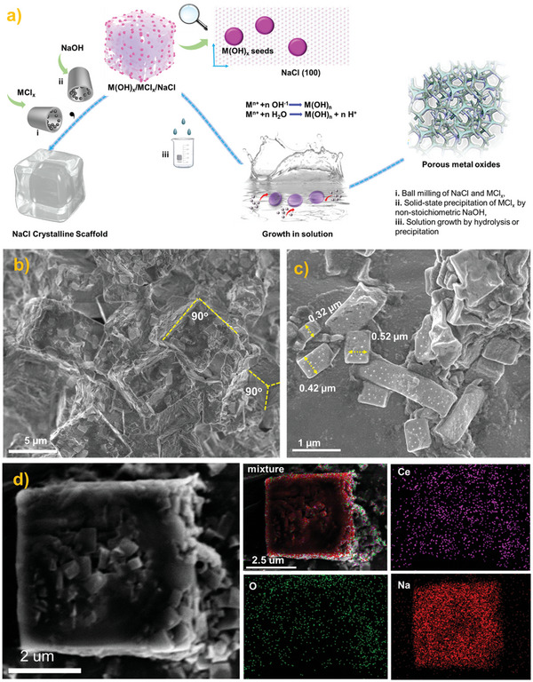
The process for building the structure of Ce(OH)3 seeds on NaCl. a) Scheme of Seeds/NaCl‐mediated growth method for porous TMOs synthesis. b) SEM image of Ce(OH)3‐CeCl3‐NaCl after the second ball‐milling. c) SEM image of Ce(OH)3‐CeCl3‐NaCl under a higher magnification. d) The EDS mappings of a selected cubic NaCl nanoparticle.
SEM equipped with an EDS detector was then utilized to carefully analyze the final morphology of NaCl, and the dispersion of Ce(OH)3 seeds after the second grinding. As seen in Figure 1b, due to a low Moh's hardness of NaCl, the NaCl nanoparticles that had experienced the first ball grinding could still be further broken down. The original cubic NaCl nanoparticles in Figure S2 (Supporting Information) with ≈10 µm were now reduced to 5 µm. In addition, some small‐size NaCl fragments from 0.3–0.5 µm were also found in the fracture surface of the large NaCl nanoparticle (Figure 1c). Interestingly, these NaCl nanoparticles still exhibited dominated {100} planes, indicating NaCl could serve as a stable cubic mound to optimize product morphology. EDS mapping was then analyzed to disclose the dispersion of Ce(OH)3 seeds on NaCl. As displayed in Figure 1d, signals of Na, Ce, and O were full coverage of the selected cubic nanoparticle, demonstrating the high dispersion of Ce(OH)3 seeds was achieved over the {100} facets of NaCl after the second ball milling. The existence of NaCl also stabilized the Ce(OH)3‐NaCl interface and avoided the aggregation of Ce(OH)3 seeds. In addition, once the removal of NaCl, the NaCl‐Ce(OH)3 interface disappeared, thus exposing the originally closed Ce(OH)3 facet for subsequent growth in solution. Generally, NaCl crystals actually worked well as solvent, seeds carrier, and capping agent.
Subsequently, a wet chemistry hydrolysis process was induced to provide a favorable seed‐mediated growth environment. Theoretically, the supported Ce(OH)3 seeds and the unreacted metal chlorine salts (CeCl3) were immediately released into an aqueous solution after dissolving the NaCl template. Meanwhile, the precipitation of unreacted CeCl3 would happen over the neighborhood Ce(OH)3 seeds by dropwise addition of NaOH solution. Therefore, the unreacted CeCl3 on NaCl crystalline was expected to play a stock‐solution‐like role, which further provided the monomers for subsequent seed growth in an aqueous solution. In addition, a large number of unsaturated crystalline facets of Ce(OH)3 seeds after removing the TMO‐NaCl interface would be exposed. Therefore, an orientation growth of CeCl3 over Ce(OH)3 seeds might occur. The out situ XRD was carefully used to monitor the growth of Ce(OH)3 seeds in the solution. As seen in Figure 2a, the Ce(OH)3 seeds exhibited a typical CeO2 crystalline, indicating rapid oxidation of Ce(OH)3 to CeO2 during ball milling. Therefore, the preclaimed Ce(OH)3 seeds were actually CeO2 seeds.
Figure 2.
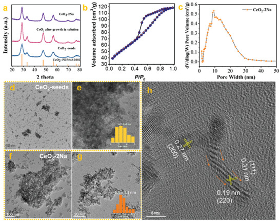
The evidence for the seeds/NaCl‐mediated growth method. a) the XRD patterns of CeO2 seeds before and after growth. b) N2 adsorption curve of CeO2‐2Na. c) the pore size distribution of CeO2‐2Na. d,e) TEM images of CeO2‐seeds with different magnifications. f,g) TEM images of CeO2‐2Na with different magnifications. h) HRTEM image of CeO2‐2Na.
Compared with the XRD pattern of CeO2 seeds, the full widths at half minimum (FHWM) of CeO2 after growth and calcination increased enormously, indicating a clear growth of CeO2 nanoparticles in size. Specifically, according to the Sheller calculation, the calculated average crystalline size of CeO2‐growth and CeO2 seeds was 5.8 and 3.7 nm, respectively. In addition, the peak intensity ratios of the (111) to (200) peaks [I(200)/I(111)] decreased from 4.24 in the CeO2 seeds to 3.33 in the CeO2‐2Na, suggesting the growth of (200) orientation were promoted by the growth in solution. More importantly, CeO2 prepared by this seeds/NaCl‐mediated growth method exhibited an ultra‐high BET SSA. Notably, the BET SSA of the optimized CeO2‐2Na sample reached 189 m2 g−1, which was nearly two folds of the CeO2 prepared by the previous solid‐state NaCl method (Figure 2b and Table 1 ).[ 22 ] Additionally, the pore size distribution of CeO2‐2Na calculated by the nonlocal density functional theory model (NLDFT) was mainly located in the range of ≈0–30 nm, indicating the formation of a mesoporous structure within CeO2‐2Na (Figure 2c).
Table 1.
The texture of porous metal oxides prepared by these seeds/NaCl‐mediated methods.
| Sample | _mmol (MClx) | NaOH amount | SSA[m2 g−1] | d [nm] a) |
|---|---|---|---|---|
| CeO2‐2Na | 2 mmol(CeCl3) | 2 mmol | 189 | 7.2 |
| CeO2‐NaCl b) | 2 mmol(CeCl3) | 6 mmol | 84 | 5.56 |
| Mn3O4‐1Na | 2 mmol(MnCl2) | 1 mmol | 147 | 13.6 |
| Mn3O4‐NaCl b) | 2 mmol(MnCl2) | 4 mmol | 79 | 17.3 |
| Nb2O5‐1Na | 1 mmol(NbCl5) | 1 mmol | 495 | 2.8 |
| Nb2O5‐NaCl b) | 1 mmol(NbCl5) | 5 mmol | 62 | 16.3 |
| Fe3O4‐2Na | 2 mmol(FeCl3) | 2 mmol | 212 | 3.6 |
| Fe3O4‐NaCl b) | 2 mmol(FeCl3) | 6 mmol | 141 | 12.3 |
| Mg(OH)2‐1Na | 2 mmol(MgCl2) | 1 mmol | 186 | 11.3 |
| Mg(OH)2‐NaCl b) | 2 mmol(MgCl2) | 4 mmol | 76 | 15.1 |
| SnO2‐1Na | 2 mmol(SnCl2) | 1 mmol | 276 | 3.9 |
| SnO2‐NaCl b) | 2 mmol(SnCl2) | 4 mmol | 83 | 6.7 |
| ZrO2‐2Na | 2 mmol(ZrCl4) | 2 mmol | 332 | 3.5 |
| ZrO2‐2Na b) | 2 mmol(ZrCl4) | 8 mmol | 152 | 6.5 |
The average pore diameter calculated by the BJH model;
The materials synthesized by the previously reported NaCl method.
The evolution of CeO2 seeds morphology and size was then carefully investigated by TEM and HRTEM. As shown in Figure 2d,e, many small and dissociative CeO2 nano aggregates after the dissolution of the NaCl crystalline scaffold were observed. Based on the above 50 random CeO2 nanoparticles in Figure 2d, the average size of CeO2 seeds was calculated as 3.1 nm, which was consistent with the calculation from the XRD (Figure 2a). The dominant facet of CeO2 seeds was {111} facets according to Figure S3 (Supporting Information), where the interplanar spacing was almost 0.31 nm. Besides the {111} facets, the {200} facets with interplanar spacing of 0.27 nm were also presented, which might be the interface of CeO2‐cubic NaCl before water washing. Interestingly, the morphology of CeO2 changed enormously after the growth in solution, original well‐dispersed CeO2 nanoparticles disappeared, and giant CeO2 nano‐aggregates occurred as the dominant morphology. Such a nanostructure was just like an interesting “Lego” building block, where the stack of CeO2 nanoaggregate made the final CeO2 rich with internal pores. With further observation in Figures 2f,g, the morphology and size of CeO2 nanoparticles after growth changed greatly. First, the average size of CeO2 after growth rapidly increased to 5.6 nm. Second, some CeO2 nanoparticles with worm‐like shape were observed. Specifically, clear worm‐like CeO2 nanoparticles were presented in Figure 2h, indicating a possible oritention growth of CeO2 seeds. In general, porous CeO2 with advantages in SSA and morphology are simultaneously synthesized by this seeds/NaCl‐mediated growth method.
Notably, this seed/NaCl‐mediated growth method for producing mesoporous or porous TMOs was a general principle that either hydrolyzed, weakly hydrolyzed, or nonhydrolyzed metal precursor salts were readily synthesized to the corresponding oxides, such as SnO2, Fe3O4, Nb2O5, ZrO2, Mn3O4, and Mg(OH)2. Specifically, the BET SSAs of SnO2, Fe3O4, Nb2O5, ZrO2, Mn3O4 and Mg(OH)2 could reach 276, 212, 495, 332, 147, and 186 m2 g−1 (Table 1 and Figure 3a). A comprehensive comparison of these BET SSAs with literature was listed in Table S1 (Supporting Information), according to the results, the BET SSAs of porous metal oxides prepared by this method reached record values in the absence of using surfactants or organic metal salts.[ 31 , 32 , 33 , 34 , 35 ] Although all the samples exhibited an evident XRD peak‐broadening phenomenon due to the small grain sizes, these metal oxide products still exhibited clear XRD diffiraction peaks (Figure S4, Supporting Information). Besides the ultra‐high BET surface areas, the synthesized oxides, e.g., Mn3O4, Mg(OH)2, and Nb2O5 also exhibited an advantage in morphology. According to Figure 3b, the Mn3O4‐1Na exhibited a particularly dendritic spine morphology. With further observation, many rod‐like Mn3O4 nanoparticles were found in the Mn3O4‐1Na, which might act as the “dendritic branches” to block the proximity of neighboring nanoparticles. In addition, the occurrence of Mn3O4 nanorods was also the trace for seed growth, because the morphology of Mn3O4 seeds was spherical (Figure S5, Supporting Information). Similarly, in the Mg(OH)2 sample, many Mg(OH)2 nanorods with a small aspect ratio were also clearly found in the TEM, which then assembled into a reef‐like morphology. TEM images of Nb2O5 also exhibited a spongy‐like microstructure with the interior filled with voids. The above facts strongly supported the effectiveness and universality of this seeds/NaCl‐mediated method.
Figure 3.

The texture of porous metal oxides by this seeds/NaCl‐mediated method. a) N2 adsorption curves of prepared porous TMOs, b) TEM images of Mn3O4‐2Na, c) TEM images of Mg(OH)2‐1Na, d) TEM images of Nb2O5‐1Na.
Typically, due to the significant differences in energy dispersive spectroscopy, the case of CoCl2 grown on hetero‐NiO seeds was then investigated, and the corresponding sample was named NiO‐Co3O4‐seed. As displayed in Figure 4a, many needle‐like nanoparticles rather than spherical ones appeared in the NiO‐Co3O4‐seed sample, which was quite different from the Co3O4 or NiO nanoparticles prepared by the NaCl‐template method.[ 22 , 36 ] The XRD diffraction of the product displayed both the Co3O4 and NiO characteristic peaks, indicating a co‐existence of NiO and Co3O4 species (Figure 4b). To further demonstrate whether Co3O4 grew on heterogeneous NiO seeds, Cs‐corrected HRTEM images and EDS elemental mappings of NiO‐Co3O4‐seed were carefully collected. As shown in Figure 4c–e, a thin nanorod and a nanoparticle attached to the side of the nanorod were exhibited. Empirically, the smaller nanoparticle with hemispherical morphology was possible as NiO seeds because the particles produced by the ball milling process were often spherical,[ 22 ] while the nanorod with well‐controlled morphology was suggested as Co3O4. Besides, the lattice spacing of 0.15 nm measured in the hemispherical nanoparticle was attributed to the NiO (220) plane,[ 37 ] while the lattice spacing of 0.47 nm in the nanorod belonged to Co3O4 (111) planes (Figure 4c).[ 38 ] Therefore, the nanoparticle and nanorod presented in Figure 4c were NiO and Co3O4, respectively. The EDS elemental analysis of NiO‐Co3O4‐seed was further adopted to demonstrate this hypothesis. According to Figure 4d, the EDS signal of Ni was only concentrated on nanoparticles with small sizes, while the Co signal was full coverage of the selected region. Accordingly, combined with the Cs‐HRTEM images and EDS elemental mappings, a possible surface deposition of Co3O4 over Ni(OH)2 occurred, where pre‐existing Ni(OH)2 nanoparticles with strong basicity might promote the accumulation of dissociated Co2+ cations to the periphery of Ni(OH)2 particles, and the subsequent precipitation of Co2+ cation would occur across the high‐index surface of NiO, e.g., the (220) planes.
Figure 4.

The characterization of hybrid NiO‐Co3O4‐seed. a) TEM image of the NiO‐Co3O4‐seed. b) the XRD diffraction of NiO‐Co3O4‐seed. c–e) Cs‐corrected HRTEM images of NiO‐Co3O4‐seed. f) HAADF image and EDS elemental mappings of NiO‐Co3O4‐seed.
Compared with the bulk metal oxides without pores, TMOs nanoparticles with rich porosity often exhibited a much‐improved redox performance. Here, having the features of ultra‐high exposed surface areas and particular rod‐like morphologies, TMOs synthesized by this method (e.g., NiO‐Co3O4‐seed) would serve well as an effective catalyst to ignite the corresponding chemical reactions. Next, the CH4 catalytic combustion reaction was used to study the redox ability of NiO‐Co3O4‐seed. In addition, the samples of NiO‐Co3O4‐P, Co3O4‐NaCl, Co3O4‐seed and Co3O4‐NiO‐seed were selected as the contrast samples (details seen in the section of Methods). Among the five catalysts, NiO‐Co3O4‐seed exhibited an excellent CH4 combustion performance. 50% CH4 completely burned into CO2 over NiO‐Co3O4‐seed occurred just at 322 °C, while the T50 over Co3O4‐seed, Co3O4‐NiO‐seed, Co3O4‐NaCl, and NiO‐Co3O4‐P was 358, 374, 383, and 510 °C, respectively (Figure 5a). Moreover, as shown in the Figure 5b, the calculated CH4 catalytic combustion activation energy (Ea) of NiO‐Co3O4‐seed was 96.8 KJ mol−1, much lower than that of Co3O4‐NaCl (115.0 KJ mol−1).
Figure 5.

The catalytic performance of NiO‐Co3O4‐seed. a) Light‐off curves of CH4 combustion over NiO‐Co3O4‐seed, Co3O4‐NaCl, and NiO‐Co3O4‐P under the WHSV of 40,000 ml g−1 s−1. b) the CH4 catalytic combustion activation energy of NiO‐Co3O4‐seed, and Co3O4‐NaCl. c) N2 adsorption curves of NiO‐Co3O4‐seed, NiO‐Co3O4‐P, and Co3O4‐NaCl. d) the CH4‐TPR curves of NiO‐Co3O4‐seed, NiO‐Co3O4‐P, and Co3O4‐NaCl. e) O 1s XPS spectra of NiO‐Co3O4‐seed, NiO‐Co3O4‐P, and Co3O4‐NaCl. f) Co 2p XPS spectra of NiO‐Co3O4‐seed, NiO‐Co3O4‐P, and Co3O4‐NaCl. g) Time‐dependent mass spectra of C16O16O, C16O18O, and C18O18O species during the 18O2 isotope labeling experiment over NiO‐Co3O4‐seed at 280 °C.
The morphology and structure of spent NiO‐Co3O4‐seed after the CH4 combustion test were also explored by TEM and XRD. According to Figure S6a (Supporting Information), the spent NiO‐Co3O4‐seed still exhibited a mixture of NiO and Co3O4 characteristic diffraction peaks, indicating no diffusion of Ni2+ into the Co3O4 lattice after the high‐temperature reaction. Besides, as shown in Figure S6b–d (Supporting Information), a hybrid nanorod and nanoparticles morphology of spent NiO‐Co3O4‐seed was retained, indicating this particular hybrid nanorod and nanoparticles morphology of NiO‐Co3O4‐seed was also thermally stable. Finally, a long‐term thermal stability testing of NiO‐Co3O4‐seed was performed under 300 °C. As shown in Figure S7 (Supporting Information), no slight deactivation of NiO‐Co3O4‐seed was observed (the CH4 conversion at the 1st h was 36.5% while the CH4 conversion at the 20th h was 29.8%). In addition, as displayed in Figure S8 (Supporting Information), no evident sintering of NiO nanoparticles or Co3O4 nanorods was observed over NiO‐Co3O4‐seed after the 20 h stability test. Therefore, the synthesized NiO‐Co3O4‐seed could act well as a robust redox catalyst.
As shown in Figure 5b, N2 adsorption indicated a similar BET SSAs of NiO‐Co3O4‐seed (121 m2/g) and Co3O4‐NaCl (130.6 m2 g−1), but the BET SSA of NiO‐Co3O4‐P was quite small only 44.0 m2 g−1. In addition, according to XPS fitting results (Figure S9, Supporting Information), the Cl−1 residues on NiO‐Co3O4‐seed, Co3O4‐NaCl, and NiO‐Co3O4‐P were calculated as 0.55, 0.86, and 6.18 atom %, respectively. Therefore, the sample of Co3O4‐NaCl was a suitable contrast sample to understand the higher activity of NiO‐Co3O4‐seed. H2‐TPR, CH4‐TPR, and XPS were further used to characterize the differences among NiO‐Co3O4‐seed, Co3O4‐NaCl, and NiO‐Co3O4‐P. Higher oxygen vacancy concentration and lower oxygen vacancy formation energy were always observed in samples of Co3O4 nanocubes or nanorods.[ 39 , 40 ] According to the data of H2‐TPR (Figure S10, Supporting Information), CH4‐TPR (Figure 5d), O1s XPS (Figure 5e) and Co 2p XPS (Figure 5f), the NiO‐Co3O4‐seed indeed exhibited the lowest H2 and CH4 reduction temperature, the highest oxygen vacancies concentration (Oads/Olat = 1.71), and the highest Co3+ concentration (Co3+/Co2+ = 0.25) among the three catalysts.
Finally, the CH4 catalytic mechanism over this NiO‐Co3O4‐seed was also glanced at by the O18 isotope labeling experiment. As shown in Figure 5g, after switching the Ar gas flow into 5 vol.% CH4, the signals of C16O16O immediately appeared and no C16O18O or C18O18O signals were observed. As the reaction time increased, the intensity of C16O16O tended to decrease due to continuous consumption of active lattice oxygen atoms or active adsorped oxygen species. To further explore which oxygen species participated in the combustion, a 5 vol.% CH4 mixture with a 1000 ppm 18O2 gas was then fed into the reaction. At the early stage (3700s–3900s), the main CO2 signals were composed of C16O16O and C16O18O, and no significant C18O18O M.S. signals were found. The presence of evident C16O18O signals indicated that the gaseous 18O2 proceeded the steps of adsorption (18O2, ads δ−), dissociation (18O2 2−, 18O2−), and the reaction, rather than the pathway that CH4 directly reacted with the adsorbed oxygen. However, further increasing reaction time, the intensity of C18O18O would also increase due to the continuous depletion of 16O lattice oxygen atoms. The 18O2 isotope labeling experiments demonstrated the CH4 combustion over NiO‐Co3O4‐seed followed a Mars‐van Kre1velen mechanism, where the oxygen vacancies concentration played a vitally important role. Therefore, the primary Co3O4 nanorods in the NiO‐Co3O4‐seed with the higher oxygen vacancies concentration were responsible for the excellent performance of the NiO‐Co3O4‐seed.
3. Conclusion
In summary, through a combination of mechanochemistry and wet chemistry, we have successfully developed a seeds/NaCl‐mediated growth protocol to fabricate porous TMOs. Interestingly, it was found that both the advantages of mechanochemistry and wet chemistry were well utilized. The ball milling process was helpful to construct seeds with much smaller sizes, and the growth of the seeds in the solution provided good morphology control. In this regard, highly porous metal meanwhile with good crystalline with a high SSA (e.g, SnO2: 275, Nb2O5: 495, ZrO2: 332, Fe3O4: 212, Mn3O4: 147, CeO2: 187, and Mg(OH)2: 186 m2 g−1) could be easily prepared. More importantly, these porous TMOs synthesized were found to have rod‐like, worm‐like, or sheet‐like primary nanoparticles. These non‐spherical nanoparticles functioned well as seeds and were further assembled into a porous network. Additionally, the prepared NiO‐Co3O4‐seed exhibited a robust CH4 catalytic combustion performance comparable to NiO‐Co3O4‐NaCl and Co3O4‐NaCl. All in all, this surfactant‐free seeds/NaCl‐mediated growth strategy could offer a new opportunity for simply and low‐costly preparing porous TMOs in the future.
Conflict of Interest
The authors declare no conflict of interest.
Author Contributions
Y.S. and Q.L. contributed equally to this work. The manuscript was written through the contributions of all authors. All authors have approved the final version of the manuscript.
Supporting information
Supporting Information
Acknowledgements
This work was supported by the National Natural Science Foundation of China (grant no. 22308172),National Natural Science Foundation of China (grant no. 22178219), National Key R & D Program Plan (2022YFA1504803 and 2020YFB0606400), Inner Mongolia R&D Program Plan (2021ZD0042, 2021EEDSCXSFQZD006, 2021GG0350), Ordos R&D Program (2121HZ231‐8). The authors would like to thank the workers in Shiyanjia Lab (www.shiyanjia.com) for the HRTEM observation. Correction added on January 5, 2024, after first online publication: The first name of C.X. was corrected.
Shu Y., Liu Q., Shi M., Zhang Z., Xie C., Bi S., Zhang P., Surfactant‐Free Synthesis of Crystalline Mesoporous Metal Oxides by a Seeds/ NaCl‐Mediated Growth Strategy. Adv. Sci. 2024, 11, 2304533. 10.1002/advs.202304533
Contributor Information
Yuan Shu, Email: closy@nxu.edu.cn.
Pengfei Zhang, Email: chemistryzpf@sjtu.edu.cn.
Data Availability Statement
The data that support the findings of this study are available from the corresponding author upon reasonable request.
References
- 1. Hu M., Yang W., Tan H., Jin L., Zhang L., Kerns P., Dang Y., Dissanayake S., Schaefer S., Liu B., Zhu Y., Suib S. L., He J., Matter 2020, 2, 1244. [Google Scholar]
- 2. Sharapa D. I., Doronkin D. E., Studt F., Grunwaldt J.‐D., Behrens S., Adv. Mater. 2019, 31, 1807381. [DOI] [PubMed] [Google Scholar]
- 3. Leenders S. H. A. M., Gramage‐Doria R., De Bruin B., Reek J. N. H., Chem. Soc. Rev. 2015, 44, 433. [DOI] [PubMed] [Google Scholar]
- 4. Lu X., Kanamori K., Nakanishi K., Nat. Sci. Rev. 2020, 7, 1656. [DOI] [PMC free article] [PubMed] [Google Scholar]
- 5. Feinle A., Elsaesser M. S., Hüsing N., Chem. Soc. Rev. 2016, 45, 3377. [DOI] [PubMed] [Google Scholar]
- 6. Parauha Y. R., Sahu V., Dhoble S. J., Mater. Sci. Eng. B. 2021, 267, 115054. [Google Scholar]
- 7. Renuka L., Anantharaju K. S., Vidya Y. S., Nagaswarupa H. P., Prashantha S. C., Sharma S. C., Nagabhushana H., Darshan G. P., Appl. Catal. B Environ. 2017, 210, 97. [Google Scholar]
- 8. Karimi S., Meshkani F., Rezaei M., Rastegarpanah A., Fuel 2021, 284, 118866. [Google Scholar]
- 9. Wang H., Zhuo S., Liang Y., Han X., Zhang B., Angew. Chem., Int. Ed. 2016, 55, 9055. [DOI] [PubMed] [Google Scholar]
- 10. Zuo X., Xia Y., Ji Q., Gao X., Yin S., Wang M., Wang X., Qiu B., Wei A., Sun Z., Liu Z., Zhu J., Cheng Y.‐J., ACS Nano 2017, 11, 889. [DOI] [PubMed] [Google Scholar]
- 11. Donaldson J. G., Schall P., Rossi L., ACS Nano 2021, 15, 4989. [DOI] [PMC free article] [PubMed] [Google Scholar]
- 12. Petkovich N. D., Stein A., Chem. Soc. Rev. 2013, 42, 3721. [DOI] [PubMed] [Google Scholar]
- 13. Baddour F. G., Nash C. P., Schaidle J. A., Ruddy D. A., Angew. Chem., Int. Ed. 2016, 55, 9026. [DOI] [PubMed] [Google Scholar]
- 14. González‐Prior J., López‐Fonseca R., Gutiérrez‐Ortiz J. I., De Rivas B., Appl. Catal. B Environ. 2018, 222, 9. [Google Scholar]
- 15. Rombi E., Cutrufello M. G., Atzori L., Monaci R., Ardu A., Gazzoli D., Deiana P., Ferino I., Appl. Catal. A Gen. 2016, 515, 144. [Google Scholar]
- 16. Jiao F., Hill A. H., Harrison A., Berko A., Chadwick A. V., Bruce P. G., J. Am. Chem. Soc. 2008, 130, 5262. [DOI] [PubMed] [Google Scholar]
- 17. Xiong H., Zhou H., Sun G.e, Liu Z., Zhang L., Zhang L., Du F., Qiao Z.‐A.n, Dai S., Angew. Chem., Int. Ed. 2020, 59, 11053. [DOI] [PubMed] [Google Scholar]
- 18. Lan K., Liu Y., Zhang W., Liu Y., Elzatahry A., Wang R., Xia Y., Al‐Dhayan D., Zheng N., Zhao D., J. Am. Chem. Soc. 2018, 140, 4135. [DOI] [PubMed] [Google Scholar]
- 19. Tarutani N., Tokudome Y., Jobbágy M., Viva F. A., Soler‐Illia G. J. A. A., Takahashi M., Chem. Mater. 2016, 28, 5606. [Google Scholar]
- 20. Feitknecht W., Schindler P., Pure Appl. Chem. 1963, 6, 125. [Google Scholar]
- 21. Roelands C. P. M., Ter Horst J. H., Kramer H. J. M., Jansens P. J., Cryst. Growth Des. 2006, 6, 1380. [Google Scholar]
- 22. Shu Y., Chen H., Chen N., Duan X., Zhang P., Yang S., Bao Z., Wu Z., Dai S., Chem 2020, 6,1723. [Google Scholar]
- 23. Pazesh S., Gråsjö J., Berggren J., Alderborn G., Int. J. Pharmaceut. 2017, 528, 215. [DOI] [PubMed] [Google Scholar]
- 24. Feng J.i, Xu D., Yang F., Chen J., Wu C., Yin Y., Angew. Chem., Int. Ed. 2021, 60, 16958. [DOI] [PubMed] [Google Scholar]
- 25. Yao Q., Yuan X., Fung V., Yu Y., Leong D. T., Jiang D.‐E., Xie J., Nat. Commun. 2017, 8, 927. [DOI] [PMC free article] [PubMed] [Google Scholar]
- 26. Liu Y., Tang A., Zhang Q., Yin Y., J. Am. Chem. Soc. 2015, 137, 11327. [DOI] [PubMed] [Google Scholar]
- 27. Tsuzuki T., Commun. Chem. 2021, 4, 143. [DOI] [PMC free article] [PubMed] [Google Scholar]
- 28. Shu Y., Wang M., Duan X., Liu D., Yang S., Zhang P., AIChE J. 2022, 68, e17664. [Google Scholar]
- 29. Shi L., Chen K.e, Du R., Bachmatiuk A., Rümmeli M. H., Priydarshi M. K., Zhang Y., Manivannan A., Liu Z., Small 2015, 11, 6302. [DOI] [PubMed] [Google Scholar]
- 30. Tai Y., Liang H., Zaki A., El Hadri N., Abshaev A. M., Huchunaev B. M., Griffiths S., Jouiad M., Zou L., ACS Nano 2017, 11, 12318. [DOI] [PubMed] [Google Scholar]
- 31. Xiong H., Gao T., Li K., Liu Y., Ma Y., Liu J., Qiao Z.‐A.n, Song S., Dai S., Adv. Sci. 2019, 6, 1801543. [DOI] [PMC free article] [PubMed] [Google Scholar]
- 32. Etacheri V., Seisenbaeva G. A., Caruthers J., Daniel G., Nedelec J.‐M., Kessler V. G., Pol V. G., Adv. Energy Mater. 2015, 5, 1401289. [Google Scholar]
- 33. Luo W., Li Y., Dong J., Wei J., Xu J., Deng Y., Zhao D., Angew. Chem., Int. Ed. 2013, 52, 10505. [DOI] [PubMed] [Google Scholar]
- 34. Wang A., Wang H., Deng H., Wang S., Shi W., Yi Z.‐X., Qiu R.‐L., Yan K., Appl. Catal. B. Environ. 2019, 248, 298,. [Google Scholar]
- 35. Feng D., Gao T.‐N., Fan M., Li A., Li K., Wang T., Huo Q., Qiao Z.‐A.n, NPG Asia Mater 2018, 10, 800. [Google Scholar]
- 36. Shu Y., Wang M., Duan X., Liu D., Yang S., Zhang P., AIChE J. 2022, 68, e17664. [Google Scholar]
- 37. Suvith V. S., Devu V. S., Philip D., Ceram. Int. 2020, 46, 786. [Google Scholar]
- 38. Liu J., Fung V., Wang Y., Du K., Zhang S., Nguyen L., Tang Y., Fan J., Jiang D.‐E., Tao F. F., Appl. Catal. B Environ. 2018, 237, 957. [Google Scholar]
- 39. Xie X., Li Y., Liu Z.‐Q., Haruta M., Shen W., Nature 2009, 458, 746. [DOI] [PubMed] [Google Scholar]
- 40. Dangwal Pandey A., Jia C., Schmidt W., Leoni M., Schwickardi M., Schüth F., Weidenthaler C., J. Phys. Chem. C 2012, 116, 19405. [Google Scholar]
Associated Data
This section collects any data citations, data availability statements, or supplementary materials included in this article.
Supplementary Materials
Supporting Information
Data Availability Statement
The data that support the findings of this study are available from the corresponding author upon reasonable request.