Abstract
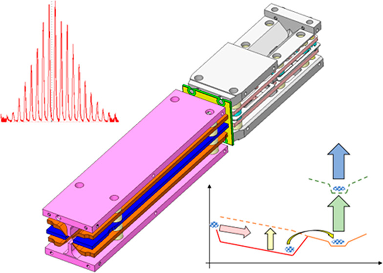
Ion traps are routinely directly coupled to mass analyzers, where they serve to suitably cool and shape an ion population prior to pulsed extraction into the analyzer proper. Such devices benefit from high duty cycle and transmission but suffer slow ion processing times caused by a compromise in the buffer gas pressure range that suitably dampens the ion kinetic energy without causing excessive scatter during extraction or within the analyzer. A rectilinear RF quadrupole ion trap has been characterized, conjoining a pressurized collision region with a pumped extraction region, and an unbroken RF interface for seamless ion transfer between them. Auxiliary electrodes mounted between the RF electrodes provide DC voltage gradients that serve to both guide ions through the device and position them at the extraction slot. The influence of the auxiliary DC upon the trapping RF field was measured, and suitable parameters were defined. A mode of operation was developed that allowed parallel processing of ions in both regions, enabling a repetition rate of 200 Hz when the device was coupled to a high-resolution accurate-mass analyzer.
Introduction
Pulsed operation analyzers, such as time-of-flight or Thermo Scientific Orbitrap analyzers, are coupled to continuous ion sources via a suitable ion preparation device. These serve to accumulate ions and imbue them with suitable spatial spread and kinetic energy distribution for the optimal function of the analyzer. Most common for time-of-flight (ToF) analyzers are orthogonal accelerators, which receive an injected packet or beam of ions and launch the ions into the analyzer via application of a pulsed extraction field.1−4 Effective usage of incoming ions comes from a high repetition rate of several kilohertz, while the number of ions sampled in a single run is small.
Orbitrap analyzers,5−8 whose analysis time is relatively long, can be coupled to an ion trap capable of both ion trapping ions in multipole RF pseudopotentials and extracting them by applying a pulsed extraction field. Such extraction traps are better adapted for lower repetition rates and offer a sensitivity advantage for their ability to accumulate up to a million ions prior to extraction, giving a high duty cycle and few transmission losses. A smaller minority of ToF analyzers also benefit from extraction traps,9−12 though a major advantage of them is expected in nascent multireflection ToF (MR ToF) analyzers with multimillisecond flight times that obstruct the kHz repetition rate of conventional orthogonal accelerators.
The downside comes in both the innate complexity of the multifunctional device, particularly in electronics, and the time penalty incurred by cooling each ion packet before it may be injected into the analyzer.
Linear (either hyperbolic or flat rectilinear) quadrupole ion traps are particularly notable for their trapping efficiency and advantageous space charge capacity over 3D Paul traps,13 without sacrifice of the strong radial compression most suitable for pulsed extraction.14 To successfully capture and thermalize ions, extraction traps are pressurized with buffer gas, usually N2 or noble gas. Greater pressure increases the rate of collisional cooling and facilitates trapping on a shorter length. However, it also increases the undesirable leakage of gas into the analyzer, and scattering of ions during pulsed extraction that leads to ion losses and metastable excitation.
Pressure levels are a perennial compromise between such competing demands, but more advanced design concepts allow circumvention. For example, pulsed gas valves are capable of temporarily generating very high pressures to cool large ions and dropping the pressure after that. The repetition rate of such valves does not, however, exceed 10 Hz15 and the valves themselves have a limited life expectancy.
This article describes a novel Ion Processor that leverages a rectilinear ion trap incorporating a pair of conjoined regions with different buffer gas concentrations.16 A dual pressure design allows task separation and parallelization, whereby one region of the trap is maintained at a relatively high pressure intended for ion capture and rapid cooling, while the other region is pumped out to a lower pressure beneficial for pulsed extraction into a mass analyzer.17 Ion transfer between the first and the second regions is performed by conjoint RF ion guides and facilitated by axial voltage profiles,18 while a gas restrictor maintains the required pressure gradient. Auxiliary DC electrodes19 drive ions along the RF ion guides and specify a location where the ions accumulate and thermalize prior to orthogonal extraction. Electrodynamic squeezing has also been used to deepen the ion trapping well and prevent escape.20
A parallel operation mode with simultaneous preparation of ion packets in both regions allows a repetition rate exceeding 200 Hz even for heavy ions such as intact proteins.
Experimental Section
Ion Processor Design
The general scheme of the Ion Processor is shown in Figure 1. The device is divided into two pressure regions, one pressurized to (0.1–2) × 10–2 mbar of nitrogen admitted via a PEEK capillary and the other directly pumped by a turbomolecular pump. A second capillary is present on the low-pressure (LP) region for admission of additional gas, if required.
Figure 1.
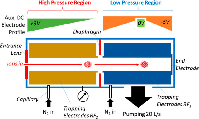
Schematic diagram of the Ion Processor including high-pressure (HP) and low-pressure (LP) regions, auxiliary DC electrode profiles.
With RF ion-guiding quadrupoles in the two regions butting up against one-another, a large-diameter diaphragm is located around their interface to act as a gas restrictor, though its radius well above the quadrupoles’ inscribed radii ensured apertureless transfer of ions. An additional gas conductance restriction is provided by the tight electrode structure and insulation between the electrodes.
Isometric and cross-sectional views of a 3D model (SOLIDWORKS21) of the Ion Processor are shown in Figure 2. The trap is formed of two adjacent stacks of wire-cut electrical discharge machined stainless steel RF and DC electrodes, mounted on alumina rods and separated either by quartz spacers or by being glued to the rods.
Figure 2.
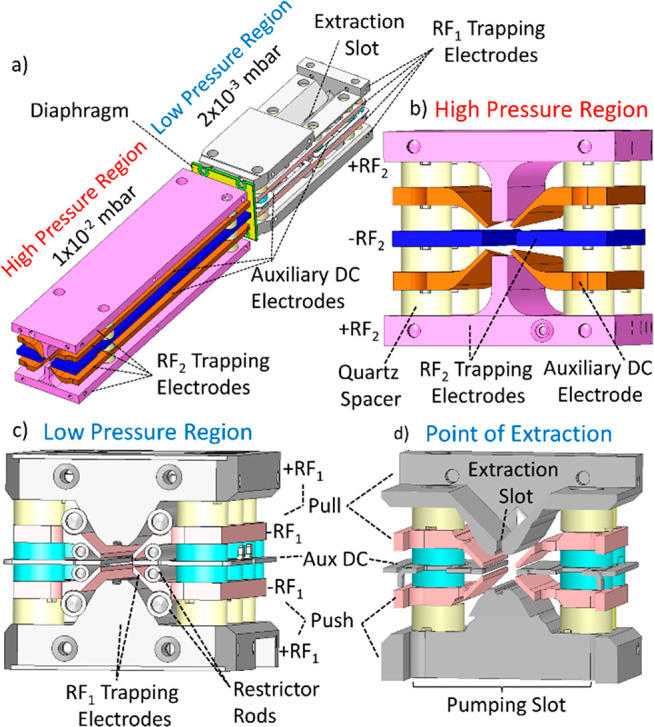
(a) Isometric view of Ion Processor architecture. (b–d) Cross-sectional views of the high and low-pressure regions of the Ion Processor, and at the point of ion extraction, respectively.
The high-pressure (HP) region (Figure 2b) is represented by 100 mm long rectilinear quadrupole electrodes ± RF2 with the inscribed radius r0 = 2 mm supplied with the 250–2000 V (peak-to-peak) RF waveform at the frequency of 3.7 MHz. The ions are admitted to the HP region through a 2 mm steel aperture acting as an entrance lens.
Four auxiliary DC electrodes are mounted diagonally between the RF electrodes. The diagonal distance between them varies from 4 mm at the end of ion entrance to 7 mm at the other end, therefore protruding a different amount into the quadrupole’s volume. When biased with a voltage offset relative to the RF electrodes, the wedge-shaped DC electrodes generate an axial field along the length of the HP region that ushers the ions toward the following low-pressure (LP) region.
The 8 cm long LP region is adapted for ion orthogonal extraction and possesses a more complicated electrode structure. Like the first region, it also comprises an RF quadrupole ± RF1 designed to have the same effective inscribed radius. When an identical RF waveform perfectly phase-locked with that in the HP region is applied, it makes a seamless connection for traveling for ions.
The whole structure of RF electrodes is adapted to generate a pulsed transversal electric field gradient in the vertical direction of Figure 2d. Accordingly, each electrode of the horizontal pair is split into two halves. The Pull vertical electrode and the upper halves of the horizontal RF electrodes receive a negative pulsed voltage −900 V, while the opposite Push electrode and the lower halves of the horizontal electrodes receive a positive pulse of the same amplitude. In contrast to applying the extraction voltage to Push and Pull electrodes only, the split pair of horizontal electrodes strengthens the extraction field at the equatorial plane and improves its uniformity.
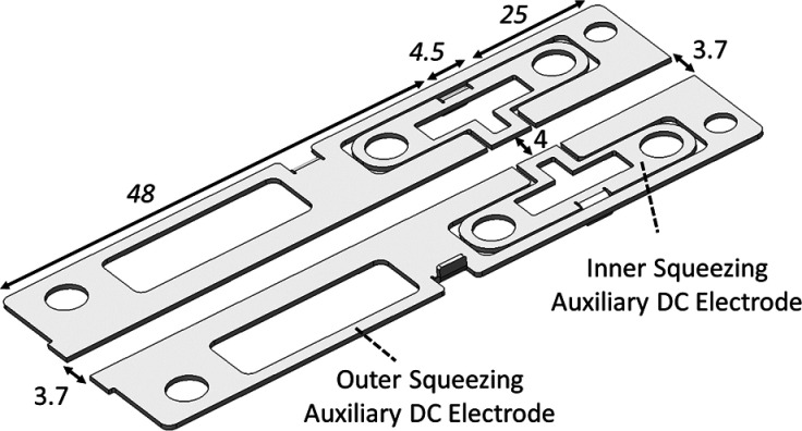
The top (Pull) electrode has a slot of 8 mm length and 0.8 mm width for ion ejection. The LP region also contains auxiliary DC electrodes peripherally mounted in the horizontal plane.22 Due to the equatorial location of the auxiliary DC electrodes, there is no need to apply any pulsed voltage to them. The DC electrodes made in the LP region of the laser-cut sheet steel coated with gold and possess more complex shapes shown in Figure 3. There are two pairs of DC electrodes that normally receive voltage offsets of different polarities with respect to the RF rods.
Figure 3.
Low-pressure (LP) region auxiliary DC electrodes with dimensions in millimeters.
The external pair of electrodes also has a wedged shape. The distance between them varies from 4 mm (flush with the split RF electrodes) in the middle and 3.7 mm at both ends, where they protrude extra 0.15 mm into the quadrupole’s volume. When applied a positive voltage offset, these electrodes generate an axial gradient that retards the ions from the ends and collects them in the middle, where the DC potential is smaller due to a wider interelectrode distance. The widest section is located right across the extraction slit in the Pull electrode, so that the ions gather in this place ready for extraction. The axial compression is further improved by the other pair of smaller DC electrodes biased negatively.
The HP part is sealed on its sides with gastight PCB plates, that also carry electrical contacts, and is pressurized with the nitrogen intake through a PEEK capillary. The regions of the trap are separated by a diaphragm of the internal diameter slightly exceeding the inscribed diameter of the RF quadrupoles. The diaphragm does not affect the ion transfer but restricts the gas flow from the HP part into the LP part.
On the contrary, the LP region is maximally open for pumping out through the slots between the electrodes and a special wide pumping window cut in the Push electrode. Such configuration generates a pressure gradient of circa an order of magnitude between the regions as the simulation shows in Figure 4. For further gas restriction between the section, eight additional PEEK cylinders may optionally be installed between the electrodes in the LP region as shown in Figure 2c, covering only a part of length.
Figure 4.
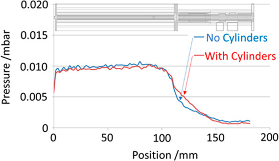
Simulated pressure profile for the Ion Processor with and without conductance-restricting cylinders between electrodes.
Trap Operation Cycle
The Ion Processor operates on a roughly 4-step cycle, described in Figure 5.23 Ions are injected into the 10–2 mbar HP region. where they are thermalized in collisions with the buffer gas. Ions may be injected with 5–200 eV, allowing optional collisional fragmentation for MS/MS spectral acquisition. The buffer gas pressure is sufficient to slow down the injected ions or their fragments on the 100 mm length of the HP region. On this stage, the HP region is set to a negative DC bias with respect to the LP region, so that the ions are unable to cross the interface. In addition, a +3 V offset on the wedged auxiliary DC electrodes is applied to usher the ions toward the interface and gather them at the very end of the HP region. Due to a relatively high buffer gas concentration, the thermalization time is short, and after ca. 1.5 ms the ion population acquires the room temperature of the buffer gas.
Figure 5.
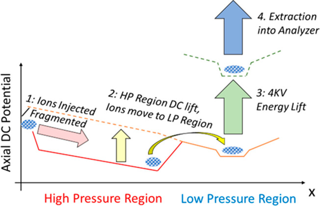
Potential and processing sequence of ions as they traverse the Ion Processor.
The HP region DC offset was then lifted to place it slightly (1–2 V) above the offset of the LP region and allow ions to drift into it. The trick is that the ions enter the LP region with already small kinetic energies, which allows short thermalization time despite of the low buffer gas pressure of 10–3 mbar. The HP region’s auxiliary DC wedges are increased +12–24 V at this point to hasten removal of straggling ions.
After a 2.5 ms delay, the ions are driven to the middle of the LP region by the axial field generated by auxiliary DC electrodes and settle in the extraction region. The LP offset is then lifted for another 1.5 ms to the potential of 4 kV, providing the ions with the required potential energy for further acceleration toward the mass analyzer. The axial trapping DC is raised to +5–10 V providing better axial compression. The trapping RF amplitude is maintained throughout the rise. At the same time, the HP region is reopened for the next incoming ion packet, so that a second packet of ions may commence processing within the device, before the preceding ion packet has completed processing and been ejected. This parallelization of separate ion processing sequences, albeit at different processing stages, is essential to allow the device to operate rapidly.
After a short programmable delay, the RF waveform applied to the LP region is abruptly quenched, first on the top and bottom electrodes, and then after 1/2 cycle on the split electrodes followed by application of 500–1000 V extraction voltages to extract the ions into the analyzer.25 The quench/extraction method was understood to combine the artifact reduction of quenching at the RF zero voltage crossing point, with the optimum trapped ion spatial and energy properties for pulsed extraction. Figure 6 shows oscilloscope traces of the 4 kV lift and extraction processes, as well as the interplay between the HP and LP regions as they cycle at 200 Hz.
Figure 6.
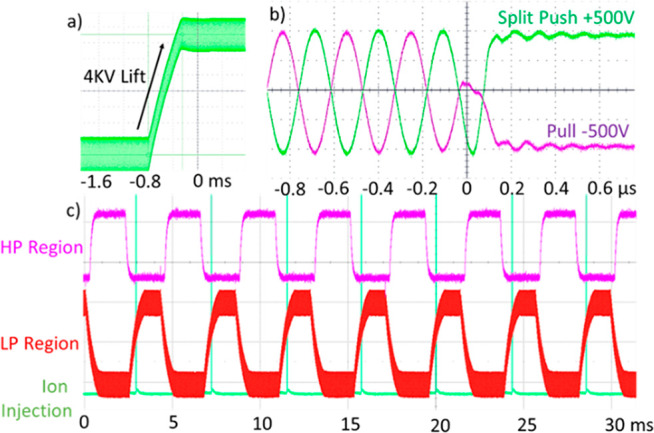
Oscilloscope traces showing (a) 4 kV voltage lift over 1.5 ms, with 1000 Vp–p RF applied throughout, and (b) quench of RF and application of 500 V push/pull extraction voltages. (c) 200 Hz cycle of the high- and low-pressure regions, along with activation of the ion injecting “split lens” that admits ions from the quadrupole filter.
Ion-Optical Simulation
Design was supported by simulation (electric fields, ion trajectories, space charge, and gas dynamics) using the MASIM3D software package.26,27
Results and Discussion
Experimental Apparatus and Characterization
A special setup was made to characterize the Ion Processor shown in Figure 7a. An ion-impact detector (Photonis) comprising a microchannel plate (MCP), scintillator, and a photomultiplier (PMT) was positioned directly in the path of the extracted ion bunch at the distance of 50 mm. A stack of apertured electrodes, with a resistive divider between them was used to accelerate the ions to the kinetic energies of 10 keV per elementary charge for reliable ion-electrode conversion on the MCP.
Figure 7.
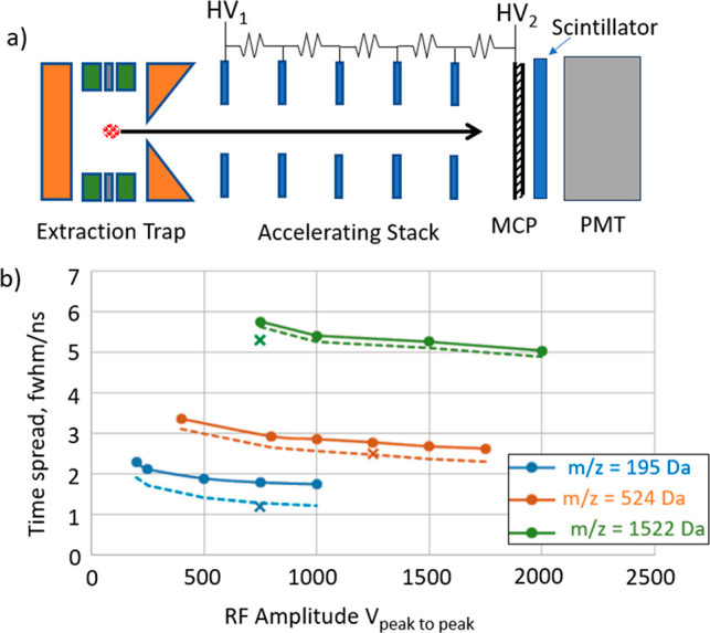
(a) Ion Processor characterization setup. (b) Time spread of the detector signal (solid), with the detector’s spread deconvoluted (dashed), simulated results (crosses).
Ion arrival time spreads are shown in Figure 7b for caffeine (m/z = 195 Da), MFRA (524 Da), and ultramark (1522 Da) ions. The acceleration voltages HV1 and HV2 were set to implement the first time-focus at MCP plate of ion detector, which corresponds to the minimal time dispersion when the ion arrival time is predominantly independent of the ion’s position in the trap when the extracting field is applied. The ToF width still depends on the ion’s energy spread due to the turn-around aberration.
The sequence of switching the RF waveform as shown in Figure 6b is beneficial to minimize the velocity spread when the push and pull voltages are applied, though the spread still depends on the RF amplitude.
The measured ToF spreads (Δt, solid lines) show a decrease with the RF amplitude, though being somewhat above the simulated values (simulation in MASIM 3D for a room-temperature trapped ion ensemble). It should be noted, however, that the ion detector itself has an intrinsic time spread of Δtdet = 1.25 ns. With this deconvoluted, the corrected ToF spreads Δt* = (Δt2 – Δt2det)1/2 (dashed lines) fit the simulated estimation with a satisfactory precision.
In the next characterization test, the detector was substituted for an imaging MCP-CCD matrix (IonCCD, OI Analytical) to measure the spatial size of the extracted ion cloud in the direction aligned with the ion trap’s axis. As shown in Figure 8, the beam spatial profile was Gaussian with the 6σ width estimated as 2.4 mm. This size matches the length 2.5 mm of the negative Auxiliary DC trapping electrodes which define the ion thermalization section of the LP region.
Figure 8.
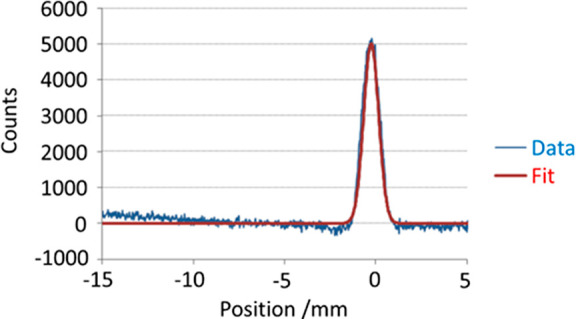
IonCCD measurement of extracted ion beam width with 2.5 mm trapping electrode.
Notably, flat trapping electrodes generate an approximately quadratic DC potential well in which the ion cloud assumes a Gaussian distribution in thermal equilibrium. This result demonstrates importance of the auxiliary DC trapping electrode for axial ion confinement.
Using Ion Processor in the Orbitrap Astral Mass-Spectrometer
The Ion Processor was installed in a prototype version of the Thermo Scientific Orbitrap Astral mass spectrometer schematically shown in Figure 9. The ion-providing front end is a modified version of a Thermo Scientific Orbitrap Exploris 480 mass spectrometer,24 which features a Quadrupole Mass Filter (QMF) for mass selection and an Orbitrap mass analyzer for comparative and diagnostic purposes.
Figure 9.
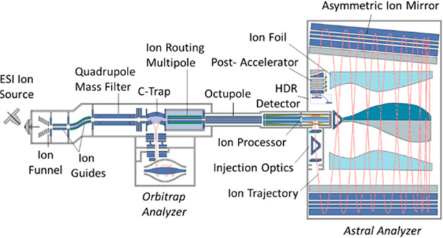
Layout of the experimental Orbitrap Astral instrument with the Ion Processor as a pulsed ion source.
Ions were generated from Pierce FlexMix calibration sample by the electrospray source and admitted to the vacuum chamber through a stainless-steel transfer tube before being captured by an ion funnel. Captured ions were forced down the ion funnel by jet expansion and passed through a series of ion guides and decreasing pressure regions, until being captured in the Ion Processor coupled to the Ion Routing Multipole (IRM) with an octapole ion guide. Optionally, the ions were mass-selected in the QMF.
After passing through the HP and LP regions as described above, the ions were orthogonally extracted from the Ion Processor toward the Astral multireflection analyzer20 that incorporates multiple oscillations between two electrostatic mirrors. With its total flight length exceeding 30 m, the Astral analyzer provides mass resolving power above 100,000.
The experiments described in the following sections involved peak intensity and resolution measurements performed on the Astral analyzer, while specific parameters were set or scanned: Space charge measurement required scanning the ion accumulation time; ion transfer investigations altered the transfer time or voltage step between pressure regions; fragmentation, or MS/MS, spectra were generated by reducing the DC offset of the HP region to induce high energy collisions. Protein measurements replaced FlexMix solution with a 1uM solution of Myoglobin, dissolved in 50:50 acetonitrile and water, as well as equivalent solution of ubiquitin and carbonic anhydrase.
Ion Capacity
The trapping capacity of the device was probed by scanning ion Inject Time during which the ions were administered into the Ion Processor. Figure 10a shows the full number of detected FlexMix ions in the wide mass range 190–3000 Th, mostly singly charged. With the Inject Time under 2 ms, the trapped space charge was not limiting, allowing extraction and detection of practically all ions stored in the Ion Processor. Therefore, a near-linear dependence of Total Ions Detected on the Inject Time (right-hand axis) was observed. At longer Injection Times, the space charge reveals itself as a reduction of a fraction of extracted ions and the under-linear further rise in Figure 10a.
Figure 10.
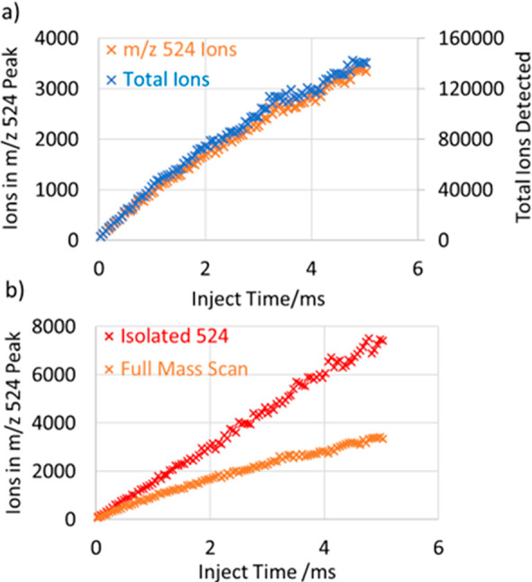
Number of detected ions vs Inject Time during which the ions were accumulated in the Ion Processor. (a) Full mass range of FlexMix ions and a fraction of MRFA ions cotrapped. (b) Comparison of the number of MRFA ions in two mass selection scenarios—isolation and cotrapping with the full mass range.
One of the factors of ion loss is Coulomb repulsion that expands the cloud of thermalized ions in the LP region and cause it to be clipped by the extraction slot. The overall ion capacity was found to be very suitable for full mass scans, as the number of trapped ions maintained a reasonably linear rise until >50,000 ions were detected in the Astral analyzer, and >140,000 ions were detected at 5 ms Inject Time.
MRFA ions (m/z = 524, left-hand axis) constituted a certain fraction of ca. 2.5% of the total number of cotrapped ions and followed the trend. Figure 10b compares the numbers of MRFA ions under two conditions: isolated in the QMF and cotrapped with the other FlexMix species. As the space charge stays small in the first case, no signs of nonlinearity were observed. This implies that ion losses were caused by space charge effects within the Ion Processor trap where ions of differing m/z are cotrapped, rather than in the Astral analyzer where ions of very different m/z are quickly separated in space.
In Figure 11, the Inject Time was varied for FlexMix resulting in different total ion counts plotted on the horizontal axis. The traces show peak intensities for ionic species with several m/z ratios, each intensity being normalized to that of the m/z = 922 Da peak in the same spectrum. The normalized peak intensities describe the space-charge related suppression for different ion masses. The species with most extreme m/z ratios, namely caffeine with m/z = 195 Da and ultramark m/z = 2722 Da are preferentially lost with the total ion number increasing.
Figure 11.
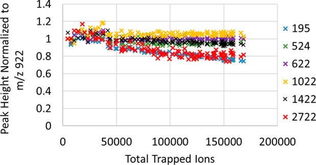
Space-charge related suppression of different m/z peaks vs the total number of trapped ions.
Suppression of the highest m/z in the mixture may be explained by stratification of RF-trapped ions into shells,28 the heaviest ions residing farthest from the axis and suffering the most from clipping by the extraction diaphragm. On the contrary, the low-m/z ions thermalize close to the axis, but the space-charge concentrated there make them spread a longer axial extent, which might also render the lightest ions beyond the length of extraction slot. The relative discrimination of high- and low-m/z is however rather mild and constitute only ca. 20%.
Ion Fragmentation
Ion collision-induced fragmentation was performed by applying a negative voltage offset to the HP region (including the RF and auxiliary DC electrodes), so that the entering ions are accelerated up to 200 eV per unit charge to induce high energy collisions in the 10–2 mbar nitrogen.
Figure 12a shows an example MS/MS spectrum of isolated m/z 1522 ultramark, fragmented in the Ion Processor and measured in Astral. For comparison, Figure 12b presents a similar spectrum obtained in Orbitrap Exploris 480 with fragmentation in IRM and recorded via the Orbitrap analyzer at the 15,000 resolution. In both cases an m/z normalized collision energy setting of 42 was used, equivalent to 86 eV standard collision energy setting.
Figure 12.
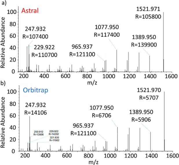
Ultramark m/z 1522 MS/MS spectrum comparison between (a) Ion Processor fragmentation following measurement in Astral and (b) IRM fragmentation following measurement in the Orbitrap analyzers.
The two results were closely comparable, showing a slightly higher fragmentation proportion in the Astral analyzer. It is noteworthy that the intensity of the m/z 230 peak is enhanced in Ion Processor at the expense of the m/z 248 peak which is a manifestation of further H2O or NH4 loss.
Comparison to a similar 1 ms-long injection of isolated ultramark ions with no fragmentation voltage offset showed that injection of circa parent 5700 ions results in about 4800 ions in the MS/MS spectrum, implying a ca. 84% efficiency.
Thanks to the double-stage cooling, one ion population is prepared for extraction in the LP region while the next group of ions simultaneously undergoes fragmentation in the HP region. The advantage of Ion Processor coupled to the Astral analyzer consists in the mass resolving power of 100,000 preserved at the 200 Hz repetition rate in the MS/MS mode.
Ion Transfer
Operation at >200 Hz requires transfer of ions between HP and LP regions within a 2–3 ms period between initiating the transfer and starting the 4 kV voltage lift. Another 1.5 ms is taken for the ions to dwell in the LP region during the voltage lift and waiting for extraction. The HP-LP transfer time defines, therefore, the available time for additional ion cooling in the LP region, a process whose efficiency also depends on the buffer gas pressure.
A series of measurements were performed with varying HP-to-LP transfer time, the results presented in Figure 13. Figure 13a shows the signal intensity for various ions at a constant LP pressure of 1.75 × 10⁻³ mbar. It shows that the time of 3 ms is practically sufficient for effective ion cooling at this pressure level thanks to a small initial energy of ion transfer. The hard ion losses at low transfer times are likely exacerbated by a delayed release of ions caused by the slow drop of the LP region from 4 kV to the transfer potential. This extends storage time in the HP region and restricts measurement of the effects of collision energy on cooling times.
Figure 13.
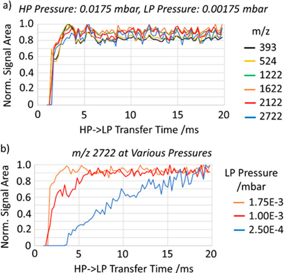
(a) Transfer time scan of various m/z ions into low-pressure region, at approximately 1.75 × 10⁻³ mbar. (b) Transfer time scans of m/z 2722 ions at a range of pressures.
Figure 13b illustrates the effect of reduced buffer gas pressure on the ion transfer efficiency. With a reduced pressure and short transfer times, the ions cannot apparently thermalize efficiently in front of the extraction slot before the extraction voltage is applied. This shows a practical limit to drop the LP pressure, which is a trade-off against the repetition rate. The pressure level of 1.75 × 10⁻³ mbar is hence proven to provide the desirable repetition rate of 200 Hz.
According to gas flow calculations shown in Figure 4, this pressure mode corresponds to the gas leakage from the HP region is the latter is pressurized to ca. 2 × 10⁻² mbar. The extra gas inlet into the LP region may be used to decouple the HP and LP pressure levels.
The next experiment was to study the effect of phase locking between the HP and LP regions on ion transmittance. To this end, we measured the signal intensities under phase-locked RF in the matching phase (0°) and the opposite phase (180°) applied to the RF ion guides both sides of the interface. An extra DC bias was applied between the HP and LP regions, having in mind that an extra acceleration may facilitate ion transmission. The measurements presented in Figure 14 were performed with the MRFA ions (m/z = 524 Da) at 800 Vpp RF on the RF electrodes in both regions. The signal intensity is shown vs the DC voltage across the HP-LP interface.
Figure 14.
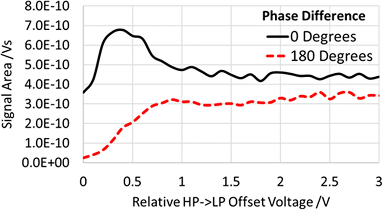
HP-LP ion transfer efficiency vs the DC offset for the 800 Vpp RF waveforms applied to HP and LP in phase or antiphase.
With the antiphase RF coupling, an extra kinetic energy had to be imparted to the ions to get them across the interface. The signal saturation is only reached at ∼1 V voltage offset. The ion losses at zero or small DC offsets are explained by annihilation of RF ponderomotive force in the vicinity of the interface where the ions experience insufficient radial confinement. Only application of an extra axial acceleration allows the ions to cross the interface fast enough to avoid losses. The adverse effect of such acceleration is the necessity to cool the ions again in the LP region under a reduced concentration of the buffer gas.
If the RF waveforms are strictly in phase, the ions may cross the HP-LP interface even with small kinetic energies that reduces the additional cooling time. Note that the transmittance reaches a maximum around the 0.4 V bias, but with an intensity likely exaggerated by release of ions trapped and left-over from previous scans.
Intact Protein Measurement
Undigested proteins represent a particular challenge for ion trap coupled analyzers; pressure must be high enough to cool the heavy, energetic ions after injection, but low enough not to scatter them excessively during extraction or in-flight through the analyzer. To achieve a sufficiently low pressure that ions survive flight paths of 10s of meters requires multiple differentially pumped stages between ion trap and the analyzer body. In C-Trap/Orbitrap instruments the trap pressure is also typically reduced by 3× when measuring intact protein samples.
Astral analysis of myoglobin (16.9 kDa) benefitted from reduced trap pressure in the same manner as Orbitrap analyzers, substantially increasing the intensities of the charge envelopes. No other special parameters were found to aid this analyte compared to the singly charged FlexMix compounds. Scattered ions were notable, however, and spectra were substantially improved by averaging to reduce the impact of these interference peaks, in addition to improved ion statistics. Figure 15 shows a full range myoglobin mass spectrum and the well-resolved 23+ charge envelope, a product of 100 averaged shots, though 5–10 was thought to be sufficient for general usage. Other samples were measured for comparison: Ubiquitin at 8.6 kDa did not require averaging at all, but 29 kDa carbonic anhydrase required tens of averages for isotopically resolved envelopes to properly emerge.
Figure 15.
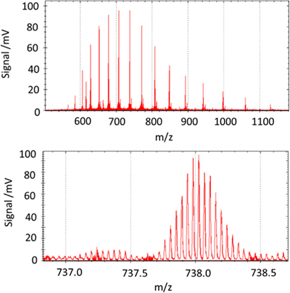
Myoglobin mass spectrum and zoomed spectrum of the 23+ charge envelope. 100× averages measured at 200 Hz repetition rate.
It was initially expected that additional cooling time would be necessary to thermalize large ions, however in practice well resolved peaks could be just as well obtained at a 200 Hz repetition rate. The likely explanation is that multiply charged ions possess a lower velocity under thermal energies than singly charged, their rate of expansion within the analyzer is lower and their potential wells within the ion processor deeper. This means that multiply charged ions need not be thermalized or cooled to the same extent as singly charged species, and thus good performance can be maintained with otherwise inadequate pressure conditions and timing.
Conclusion
An extraction ion trap has been developed and characterized incorporating dual pressure regions with an apertureless interface, and auxiliary DC electrodes to provide axial transport and trapping. This Ion Processor was shown to suitably process ions as a fragmentation and preparation device for a high-resolution accurate-mass analyzer, supporting a 200 Hz repetition rate.
Acknowledgments
The authors are grateful for the advice and support of colleagues throughout Thermo Fisher Scientific, and of the work of our industrial collaborators. Part of this work has been funded as part of the MSmed project that has received funding from the European Union’s Horizon 2020 Research and Innovation program under Grant Agreement No. 686547.
Supporting Information Available
The Supporting Information is available free of charge at https://pubs.acs.org/doi/10.1021/jasms.3c00311.
Additional images of the Ion Processor; further optimization to the mechanical design; measurement of intact carbonic anhydrase MS and MS/MS; analysis of the pseudopotential well interference generated by auxiliary DC electrodes, and optimization of applied dynamic DCs (PDF)
The authors declare the following competing financial interest(s): All authors are employees of Thermo Fisher Scientific, the manufacturer of instrumentation used in this research.
Supplementary Material
References
- Guilhaus M.; Selby D.; Mlynski V. Orthogonal acceleration time-of-flight mass spectrometry. Mass Spectrom. Rev. 2000, 19 (2), 65–107. . [DOI] [PubMed] [Google Scholar]
- Chernushevich I. V.; Loboda A. V.; Thomson B. A. An introduction to quadrupole–time-of-flight mass spectrometry. Journal of mass spectrometry 2001, 36 (8), 849–865. 10.1002/jms.207. [DOI] [PubMed] [Google Scholar]
- Chernushevich I. V.; Merenbloom S. I.; Liu S.; Bloomfield N. A W-geometry ortho-TOF MS with high resolution and up to 100% duty cycle for MS/MS. Journal of The American Society for Mass Spectrometry 2017, 28 (10), 2143–2150. 10.1007/s13361-017-1742-8. [DOI] [PubMed] [Google Scholar]
- Collings B. A.; Campbell J. M.; Mao D.; Douglas D. J. A combined linear ion trap time-of-flight system with improved performance and MSn capabilities. Rapid Commun. Mass Spectrom. 2001, 15 (19), 1777–1795. 10.1002/rcm.440. [DOI] [PubMed] [Google Scholar]
- Eliuk S.; Makarov A. Evolution of Orbitrap Mass Spectrometry Instrumentation. Annual Review of Analytical Chemistry 2015, 8 (1), 61–80. 10.1146/annurev-anchem-071114-040325. [DOI] [PubMed] [Google Scholar]
- Makarov A.; Denisov E.; Kholomeev A.; Balschun W.; Lange O.; Strupat K.; Horning S. Performance evaluation of a hybrid linear ion trap/orbitrap mass spectrometer. Analytical chemistry 2006, 78 (7), 2113–2120. 10.1021/ac0518811. [DOI] [PubMed] [Google Scholar]
- Senko M. W.; Remes P. M.; Canterbury J. D.; Mathur R.; Song Q.; Eliuk S. M.; Mullen C.; Earley L.; Hardman M.; Blethrow J. D.; Bui H.; Specht A.; Lange O.; Denisov E.; Makarov A.; Horning S.; Zabrouskov V. Novel Parallelized Quadrupole/Linear Ion Trap/Orbitrap Tribrid Mass Spectrometer Improving Proteome Coverage and Peptide Identification Rates. Anal. Chem. 2013, 85 (24), 11710–11714. 10.1021/ac403115c. [DOI] [PubMed] [Google Scholar]
- Hardman M.; Makarov A. A. Interfacing the Orbitrap mass analyzer to an electrospray source. Anal. Chem. 2003, 75, 1699–1705. 10.1021/ac0258047. [DOI] [PubMed] [Google Scholar]
- Michael S. M.; Chien M.; Lubman D. M. An ion trap storage/time-of-flight mass spectrometer. Review of scientific instruments 1992, 63 (10), 4277–4284. 10.1063/1.1143725. [DOI] [Google Scholar]
- Qian M. G.; Lubman D. M. Procedures for Tandem Mass Spectrometry on an Ion Trap Storage/Reflectron Time-of-flight Mass Spectrometer. Rapid communications in mass spectrometry 1996, 10 (15), 1911–1920. . [DOI] [PubMed] [Google Scholar]
- Schmid P. C.; Greenberg J.; Miller M. I.; Loeffler K.; Lewandowski H. J. An ion trap time-of-flight mass spectrometer with high mass resolution for cold trapped ion experiments. Rev. Sci. Instrum. 2017, 88 (12), 123107. 10.1063/1.4996911. [DOI] [PubMed] [Google Scholar]
- Franzen J.Method and device for orthogonal ion injection into a time-of-flight mass spectrometer. United States Patent US5763878, 1998.
- Schwartz J. C.; Senko M. W.; Syka J. E. A two-dimensional quadrupole ion trap mass spectrometer. J. Am. Soc. Mass Spectrom. 2002, 13 (6), 659–669. 10.1016/S1044-0305(02)00384-7. [DOI] [PubMed] [Google Scholar]
- Sudakov S.; Ding L.. Tandem ion-trap time-of-flight mass spectrometer. United States Patent US7897916, 2011.
- Raptakis E.; Papanastasiou D.; Bowdler A.. Method and apparatus for thermalization of ions. United States Patent US8198582, 2007.
- Olsen J. V.; Schwartz J. C.; Griep-Raming J.; Nielsen M. L.; Damoc E.; Denisov E.; Lange O.; Remes P.; Taylor D.; Splendore M.; Wouters E. R.; Senko M.; Makarov A.; Mann M.; Horning S. A dual pressure linear ion trap Orbitrap instrument with very high sequencing speed. Mol. Cell. Proteomics 2009, 8 (12), 2759–2769. 10.1074/mcp.M900375-MCP200. [DOI] [PMC free article] [PubMed] [Google Scholar]
- Stewart H.; Grinfeld D.; Giannakopulos A.; Petzoldt J.; Shanley T.; Garland M.; Hock C.. Parallelized Acquisition of Orbitrap and Astral Analyzers Enables High-Throughput Quantitative Analysis. bioRxiv, June 5, 2023. 10.1101/2023.06.02.543408. [DOI] [PMC free article] [PubMed]
- Giles R.; Gill M. C.. Ion Trap. United States Patent US10600631, 2020.
- Stewart H.; Hock C.; Giannakopulos A.; Grinfeld D.; Heming R.; Makarov A.. A rectilinear pulsed-extraction ion trap with auxiliary axial DC trapping electrodes. In Proceedings of the 66th ASMS Conference on Mass Spectrometry and Allied Topics; San Antonio, TX, 2018. [Google Scholar]
- Stewart H.; Makarov A. A.; Hock C. A.. Injection of ions into an ion storage device. United States Patent US11031232, 2020.
- BIOVIA, Dassault Systèmes; SOLIDWORKS: San Diego, 2022. [Google Scholar]
- Stewart H.; Grinfeld D.; Wagner A.. Ion trap, United States Patent Application US20220319828, 2022.
- Stewart H.; Grinfeld D.; Hock C.; Giannakopulos A.; Wagner A.; Kholomeev A.; Biel M.; Makarov A.. Ion transport between ion optics devices at different gas pressures, German Patent Application DE102022126981, 2022.
- Bekker-Jensen D. B.; Martinez-Val A.; Steigerwald S.; Ruther P.; Fort K. L.; Arrey T. N.; Harder A.; Makarov A.; Olsen J. V. A compact quadrupole-Orbitrap mass spectrometer with FAIMS interface improves proteome coverage in short LC gradients. Mol. Cell. Proteomics 2020, 19 (4), 716–729. 10.1074/mcp.TIR119.001906. [DOI] [PMC free article] [PubMed] [Google Scholar]
- Hock C. H.; Grinfeld D.; Heming R.. Ion ejection from a quadrupole ion trap. United States Patent US9312114, 2015.
- Monastyrskiy M. A.; Greenfield D. E.; Tarasov V. A.. MASIM 3D package for precise CPO calculations based on perturbation technique. In Software Demonstrations Abstract Book, ‘CPO-7’International Conference; Cambridge, UK, 2006; p 23.
- Grinfeld D. E.; Kopaev I. A.; Makarov A. A.; Monastyrskiy M. A. Equilibrium ion distribution modeling in rf ion traps and guides with regard to Coulomb effects. Nuclear Instruments and Methods in Physics Research Section A: Accelerators, Spectrometers, Detectors and Associated Equipment 2011, 645 (1), 141–145. 10.1016/j.nima.2010.12.168. [DOI] [Google Scholar]
- Tolmachev A. V.; Udseth H. R.; Smith R. D. Radial stratification of ions as a function of mass to charge ratio in collisional cooling radio frequency multipoles used as ion guides or ion traps. Rapid Commun. Mass Spectrom. 2000, 14 (20), 1907–1913. . [DOI] [PubMed] [Google Scholar]
Associated Data
This section collects any data citations, data availability statements, or supplementary materials included in this article.


