

Abstract
Introduction:
Conventionally, the fattened beam is being used in radiotherapy for routine clinical cases even after introduction of intensity-modulated radiotherapy with incorporation of multi-leaf collimator system. With the removal of the flattening filter (FF) from the beam’s path average energy of the photon gets reduced resulting in reduced scatter, reduction in treatment time, and reduced neutron contamination for high-energy beam and ultimately resulting in treatment plan quality deviations. This study aims to investigate the usefulness of the FF-free (FFF) beam for routine head-and-neck cancer (HNC) cases treated with volumetric arc therapy (VMAT) and dosimetrically compares the result with the FF beam.
Materials and Methods:
In this study, 20 patients treated on HalcyonTM (unmatched 6 megavoltage [6MV] FFF beam) medical linear accelerator with VMAT of different HNC selected and for comparison with 6MV FF beam, 20 equivalent treatment plans are created for TruebeamTM configuration and the plans have been evaluated for target coverage, doses to the organ at risk (OAR), and other dose quality indices.
Results:
Comparable target coverage, doses to OARs except for rest right parotid (P = 0.02) between 6MV FFF beam and 6MV FF beam is observed. Insignificant differences in conformity index, homogeneity index, and gradient index have been observed. Higher monitor unit (MU) (P ≤ 0.001) and lesser beam on time (BOT) (P = 0.003) have been observed in 6MV FFF.
Conclusion:
6MV FFF beam provides comparable target coverage and improved dose-sparing effect to most of the OARs. 6MV FFF beam has lesser BOT, but on the other hand number of MUs is higher as compared to 6MV-FF plans.
Keywords: 6 megavoltage flattening filter beam, flattening filter free, head-and-neck cancer, unmatched 6 megavoltage flattening filter-free beam, volumetric arc therapy
INTRODUCTION
Head-and-neck cancer (HNC) is the seventh most common cancer globally, accounting for 660,000 new cases and nearly half of its deaths annually. The trend of HNC occurrence appears to be increasing every year. Around 55%–60% of global HNC cases appear in South Asia. In India, HNC account for about one-third of all cancer cases followed by cervix and breast cancer. The male population has the majority burden of HNC and around 70%–75% of them present in the advanced stage.[1,2]
In recent years with the increased number of cancer cases, the demand for radiotherapy treatment has rapidly increased. Intensity-modulated radiotherapy (IMRT) and volumetric arc therapy (VMAT) techniques are becoming more popular due to the evolution and advancement in radiotherapy equipment and their capabilities to deliver precise treatment. Several studies have highlighted that due to more number of monitor units (MUs) (normally 3–5 times that of three-dimensional conformal radiotherapy [3DCRT]), more low dose spillage, increase in treatment time, more scatter, more leakage as compared to 3DCRT, it is logical to use flattening filter-free (FFF) beam, as removal of flattening filter (FF) has been found to reduce scatter, reduction in treatment time and reduced neutron contamination for high energy beam. The trend of using FFF beam for treating cancer patients has increased. Modern linear accelerators have the capability of producing an FFF beam with a greater degree of modulation due to higher multileaf collimator (MLC) speed, increased dose rate, and more gantry rotation per minute (RPM). An increase in dose rate with FFF beam helps in reducing overall treatment time.[3,4]
An unmatched FFF beam means energy is not matched with that of nominal energy, i.e., percentage depth dose (PDD) at 10 cm is not exactly matched to that of the FF beam. The FFF beam produced has a lower mean energy than the FF beam. In the FFF beam, a flat 2 mm copper filter is positioned, at the location where the FF is located in the FF beam to remove contamination of electrons that may have penetrated the target through normal use or target damage, while also producing sufficient secondary electrons for the monitor chambers to respond.
This study aims to quantitatively compare the dosimetric differences between an unflattened beam from an O-ring gantry system (HalcyonTM) and a FF beam from a C-arm (TruebeamTM) linear accelerator (M/s Varian Medical System, Palo Alto, CA) and to evaluate the usefulness of the FFF beam for routine HNC cases treated with VMAT.
MATERIALS AND METHODS
Patient selection
Retrospectively, 20 patients treated with FFF photon beam on HalcyonTM medical linear accelerator with VMAT of different HNC were selected for this study. Clinically, all patients were treated with 6 megavoltage (6MV) FFF beam and for comparison with FF beam, 20 equivalent treatment plans were created for TruebeamTM configuration. HalcyonTM version 3.0 bold model medical LA O-ring gantry system comes with a 6MV unmatched FFF beam with a jawless design. This system has seamless patient throughput due to the newly designed dual-layer stacked and staggered MLC, having two banks named proximal and distal. These MLCs have reduced transmission, reduced leakage, and 114 leaves (29 pair/bank on proximal and 28 pair/bank on distal) producing leaf effect of 5 mm at isocenter for treatment of patients, as both the banks within offset with respect to each other by 5 mm, high-dose rate (800 cGy/min), higher MLC speed (5 cm/s), four gantry rotation per minute (4 RPM), and capable of producing maximum 28 cm × 28 cm field size for clinical use. Unlike conventional LA, it has no light field. The MV imager equipped with amorphous silicon (a-Si) 1200 detector panel fixed at a distance of 154 cm from the source, has a physical size of 43 cm × 43 cm with a 28 cm × 28 cm iso-centric projection and dose rates of 9 cGy/min and 15 cGy/min for imaging, while the TruebeamTM version 2.0 LA is equipped with various photon and electron energies, millennium-120 MLC (having central 40 pairs of leaf width 5 mm and outer 20 pairs having 10 mm leaf width projected at isocenter), 2.5 cm/s maximum MLC speed, variable dose rate, one gantry rotation per minute (1 RPM)and capable of producing maximum 40 cm × 40 cm field size. The MV and kilo voltage imager panel is equipped with amorphous silicon (a-Si) 1000 detector panel with an active area of 30 cm × 40 cm. Patient simulation is performed on GE Optima 580 CT simulator with a 2.5 mm slice thickness. Image fusion, contouring, planning, and plan evaluation are performed on Eclipse treatment planning system (TPS) version 16.1.0. (Varian Medical System, Palo Alto, CA, USA).
Treatment planning strategy
Treatment plans were generated using Eclipse TPS version 16.1.0 with FFF and FF beam for 6MV energy by considering goals to achieve target doses as well as minimizing doses to organs at risk (OARs). A dose of 69.96Gy, 63Gy, and 54Gy was prescribed for high-risk, intermediate-risk, and low-risk planning target volume in 33 fractions, respectively. Quantitative Analyses of Normal Tissue Effects in the Clinic guidelines were used for specifying goals to OARs, for example, mean dose (Dmean) to the cochlea, parotids, and larynx were <45Gy, <26Gy, and <45Gy, maximum dose (Dmax) constraints for brainstem, lens, mandible, and spinal cord are 54Gy, 7Gy, 74Gy, and 45Gy, respectively. Plans were generated using two full arcs. The calculation grid spacing was kept at 2.5 mm. Optimization was performed with a photon optimizer (PO_16.1.0) with 7 iteration steps employed and volume dose calculation was performed with an anisotropic analytic algorithm (AAA_16.1.0). Optimization parameters were kept the same for the FF plan as for the clinically delivered FFF plan.
Plan evaluation strategy
Dose-volume histogram (DVH) analyses were performed with the DVH estimation algorithm (16.1.0) for target volumes and OARs. Dosimetric indices, i.e., conformity index (CI), homogeneity index (HI), gradient index (GI), integral dose (ID), and skin dose (SD) were evaluated.
Conformity index
CI quantitatively assesses the quality of the treatment plan. It represents how well a target is confined with a prescription isodose line; it establishes a relationship between isodose distribution and target volume.
CIRTOG = VRI/TV (1)
where, VRI = Reference isodose volume (V95% is taken as reference isodose volume) and TV = Target volume.
Homogeneity index
HI is a measure of dose distribution uniformity across target volume.
HI = (D2% - D98%)/(D50%) (2)
where D2%, D50%, and D98% are the doses received by 2%, 50%, and 98% volumes of PTV, respectively.
The homogeneity value ranges from 0 to 1. The ideal value of the HI is 0. A higher value represents a lack of homogeneity.
Gradient index
GI represents the measure of dose fall-off. It is used to evaluate radiation dose gradient outside the target, basically a ratio of half of prescription isodose to prescription isodose.
GI = V50%/VRI (3)
where V50% = 50% isodose volume and VRI = Reference isodose volume.
Integral dose
ID refers to the whole energy absorbed within the organ. It is well known that ID is directly associated with secondary malignancy as an increase of energy deposition in healthy tissues might play a major role in the induction of secondary cancers.[5] Aoyama et al. used three factors, i.e., mean organ dose, mean organ volume, and mean organ density to quantify the ID.[6]
ID = D [Gy] mean X V [L] mean X ρ mean (4)
where D [Gy] mean is the mean organ dose, V [L] mean (where L – liter) is organ volume and ρ mean is the mean organ density.
The ID with variable densities requires a complex calculation. For simplicity, we have considered a uniform density for the whole body volume. Hence, equation (4) can be rewritten as,
ID = D mean X V mean (Gy-L) (5)
Skin dose
VMAT plans are optimized for target coverage and normal tissue sparing by considering the basic goal of radiotherapy into account, to maximize tumor control (TC) probability and to minimize normal tissue complication probability. Skin contour delineated by creating a 3 mm shell layer inside the patient’s external contour.
Statistical analysis
Data were expressed as the mean ± standard deviation and it was analyzed using SPSS version 2020 software (SPSS, Inc., Chicago, IL, USA). The Student’s t-test was used to analyze the differences between the FFF beam plans and FF beam plans. P < 0.05 were considered to be statistically significant.
RESULTS
The PDDs of 6MV FFF and FF photon beam at 10 cm depth measured in water phantom are 61.6% and 66.7%, respectively. The planning target volume is divided into high-risk planning target volume (PTV HR), intermediate-risk planning target volume (PTV IR), and low-risk planning target volume (PTV LR). Maximum and minimum volumes are 232.16 cubic centimeter (cc) and 104.31 cc for PTV HR, 324.52 cc and 232.11 cc for PTV IR, and 155.53 cc and 47.93 cc for PTV LR, respectively, and mean volume is 168.40 cc for PTV HR, 208.37 cc for PTV IR, and 116.08 cc for PTV LR. Percentage volumes receiving 95% of the prescription dose (V95%) are shown in Table 1 for PTV LR, PTV IR, and PTV HR for 6MV-FFF beam and 6MV-FF beam.
Table 1.
V95% evaluation performed with dose-volume histogram of planning target volumes for 6 mega voltage-flattening filter-free and 6 mega voltage-flattening filter beams
| Structure | Variables | Mean±SD | P | |
|---|---|---|---|---|
|
| ||||
| Unmatched FFF beam: Ratio of total structure volume (%) | FF beam: Ratio of total structure volume (%) | |||
| PTV LR | V95% | 98.00±1.57 | 97.73±1.95 | 0.82 |
| PTV IR | V95% | 97.93±0.54 | 97.45±1.67 | 0.23 |
| PTV HR | V95% | 97.54±0.80 | 97.53±1.21 | 0.98 |
SD: Standard deviation, FF: Flattening filter, FFF: FF free, PTV LR: Low-risk planning target volume, PTV IR: Intermediate-risk planning target volume, PTV HR: High-risk planning target volume
Figures 1 and 2 show the V95% dose color wash and DVH analysis for one of the FFF and FF beam cases. V95% is comparable for 6MV-FFF and 6MV-FF beam.
Figure 1.

Comparison of V95% dose color wash of one of the volumetric arc therapy case for 6 megavoltage-flattening filter free and 6megavoltage-flattening filter treatment plans
Figure 2.

Dose volume histogram analysis for one of the volumetric arc therapy cases for 6 megavoltage-flattening filter-free and 6 megavoltage-flattening filter treatment plans
Table 2 shows the dosimetric evaluation for various OARs, Table 3 shows the ID for associated OARs, and Table 4 shows plan quality metrics: CI, HI, and GI including the number of MUs, beam on time (BOT) and SD for 6MV-FFF and 6MV-FF beams.
Table 2.
Dosimetric indices evaluation of various organs at risk for 6 mega voltage-flattening filter-free and 6 mega voltage-flattening filter beams
| Structure | Variables | Dose (Gy), mean±SD | P | |
|---|---|---|---|---|
|
| ||||
| Unmatched FFF beam | FF beam | |||
| Brainstem | Dmax | 37.92±14.65 | 36.81±14.97 | 0.81 |
| Choclea R | Dmean | 16.37±12.71 | 14.75±11.55 | 0.68 |
| Choclea L | Dmean | 16.87±11.41 | 15.21±10.67 | 0.64 |
| Lens R | Dmax | 3.75±1.88 | 4.09±2.95 | 0.67 |
| Lens L | Dmax | 3.83±2.00 | 3.86±2.93 | 0.97 |
| Parotid R | Dmean | 31.91±11.62 | 33.69±12.21 | 0.64 |
| Parotid L | Dmean | 35.45±15.63 | 36.65±15.42 | 0.81 |
| Parotid R-PTV | Dmean | 21.55±3.17 | 24.59±4.46 | 0.02 |
| Parotid L-PTV | Dmean | 22.95±3.62 | 24.96±4.47 | 0.13 |
| Mandible | Dmax | 69.22±4.49 | 69.13±4.65 | 0.95 |
| Mandible-PTV | Dmax | 65.91±3.95 | 66.07±4.10 | 0.90 |
| Spinal cord | Dmax | 38.35±6.33 | 38.43±6.68 | 0.97 |
| PRV spinal cord | Dmax | 42.42±9.55 | 42.39±9.94 | 0.99 |
| Larynx | Dmean | 53.18±9.68 | 53.62±9.65 | 0.89 |
| Larynx-PTV | Dmean | 45.15±6.67 | 45.97±6.78 | 0.70 |
PTV: Planning target volume, SD: Standard deviation, FF: Flattening filter, FFF: FF free, PRV: Planning organ at risk volume
Table 3.
Comparison of integral doses to the organs at risk for unmatched 6 mega voltage-flattening filter-free and 6 mega voltage-flattening filter beam
| Structure | ID (Gy-L), mean±SD | P | |
|---|---|---|---|
|
| |||
| Unmatched FFF beam | FF beam | ||
| Brainstem | 0.86839±0.33546 | 0.84301±0.34289 | 0.81 |
| Choclea R | 0.00164±0.00127 | 0.00148±0.00116 | 0.68 |
| Choclea L | 0.00169±0.00114 | 0.00152±0.00107 | 0.63 |
| Lens R | 0.00075±0.00038 | 0.00082±0.00059 | 0.66 |
| Lens L | 0.00077±0.00040 | 0.00077±0.00059 | 1.00 |
| Parotid R | 0.81691±0.29738 | 0.86256±0.31249 | 0.64 |
| Parotid L | 0.70183±0.30953 | 0.72567±0.30534 | 0.81 |
| Parotid R-PTV | 0.36855±0.05428 | 0.42051±0.07625 | 0.02 |
| Parotid L-PTV | 0.28688±0.04528 | 0.31198±0.05585 | 0.13 |
| Mandible | 4.90063±0.31763 | 4.89425±0.32899 | 0.95 |
| Mandible-PTV | 2.94612±0.17645 | 2.95336±0.18334 | 0.90 |
| Spinal cord | 1.36129±0.22485 | 1.36417±0.23728 | 0.97 |
| PRV spinal cord | 3.70767±0.83510 | 3.70473±0.86852 | 0.99 |
| Larynx | 1.52625±0.27773 | 1.53881±0.27695 | 0.89 |
| Larynx-PTV | 1.00243±0.14810 | 1.02061±0.15053 | 0.70 |
PTV: Planning target volume, SD: Standard deviation, FF: Flattening filter, FFF: FF free, PRV: Planning organ at risk volume
Table 4.
Comparison of conformity index, homogeneity index, gradient index, monitor unit, beam on time, and skin dose for 6 mega voltage-flattening filter-free and 6 mega voltage-flattening filter beams
| Indices | Mean±SD | P | |
|---|---|---|---|
|
| |||
| Unmatched FFF beam | FF beam | ||
| CI | 0.78±0.10 | 0.74±0.08 | 0.17 |
| HI | 0.08±0.02 | 0.11±0.10 | 0.20 |
| GI | 3.85±1.19 | 3.87±1.24 | 0.96 |
| MU | 638.31±80.44 | 498.00±36.75 | <0.001 |
| BOT (s) | 125.00±07.22 | 133.50±09.50 | 0.003 |
| Skin dose (Dmax) | 72.44±06.36 | 71.15±06.28 | 0.52 |
CI: Conformity index, HI: Homogeneity index, GI: Gradient index, MU: Monitor unit, BOT: Beam on time, SD: Standard deviation, FF: Flattening filter, FFF: FF free
DISCUSSIONS
It is well known that the removal of the FF from the path of the beam ultimately increases the dose rate. Thus FFF beam has a potential advantage, especially for small targets requiring high dose per fraction (stereotactic radiosurgery and stereotactic body radiation therapy). The concept of the FFF beam developed after the implementation of IMRT only when researchers started thinking about why not to take advantage of unflattened beams to achieve better modulation, ultimately leading to an increase in the trend of using FFF beams for routine IMRT/VMAT cases. It is important to emphasize the significance of comparing the Halcyon treatment plan with the Truebeam plan, particularly because the Truebeam Linac offers a FFF beam with a higher dose rate of 1400 MU/min, whereas the Halcyon Linac operates at a dose rate of 800 MU/min.
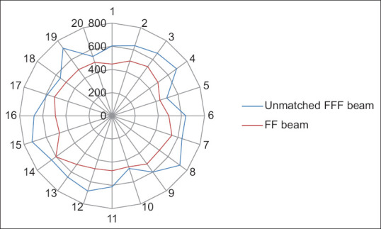
Previous researchers investigated the feasibility of using FFF beam for different treatment sites. In this context, Gasic et al. showed that it is possible to produce FFF-VMAT plans with the same target dose coverage and doses to OARs as STD-VMAT plans. Target dose homogeneity tended to be somewhat inferior for FFF-VMAT for the larger targets investigated. For stereotactic radiotherapy, FFF-VMAT resulted in a considerable time gain while maintaining similar plan quality compared to STD beams. They concluded that FFF beams are suitable for small target volumes with high doses per fraction, while considerable time gain was obtained.[7] The present study also yielded similar results for target coverage and doses to OARs except for the remaining right parotid outside planning risk volume, (parotid R-PTV) [(21.55 ± 3.17 vs. 24.59 ± 4.46) (P = 0.02)]. Furthermore, IDs are found comparable for both FFF beam and FF beam except for parotid R-PTV, i.e., rest right parotid [(368.55 ± 54.28 vs. 420.51 ± 76.25) (P = 0.02)]. Figure 3 shows the result of ID comparison between 6MV-FFF and 6MV-FF beams.
Figure 3.
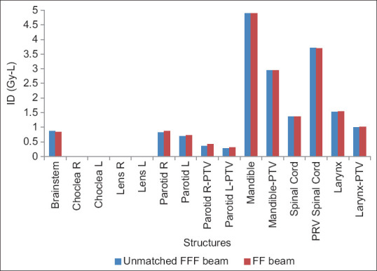
Integral dose comparison between 6 megavoltage-flattening filter free and 6megavoltage-flattening filter beams in volumetric arc therapy for head-and-neck cancer
Dalaryd investigated the effects of removing the FF on the resulting photon beam properties. They found that the delivered dose per unit time is increased approximately twofold when the FF is removed, and the variation of scattered radiation with field size is also reduced. The photon energy spectra for FFF beams are softer resulting in steeper absorbed dose fall-off with depth and less lateral energy variation across the field.[8] In this study, we have investigated the dosimetric benefit of the 6MV-FFF beam against the 6MV-FF beam for VMAT of HNC. It is observed that 6MV-FFF beam plans are dosimetrically equivalent to 6MV-FF plans. Either of the two can be used to clinically treat patients. From the BOT point of view, FFF plans to provide great benefit (P = 0.003), which ultimately helps in reducing the impact of systematic as well as random errors.
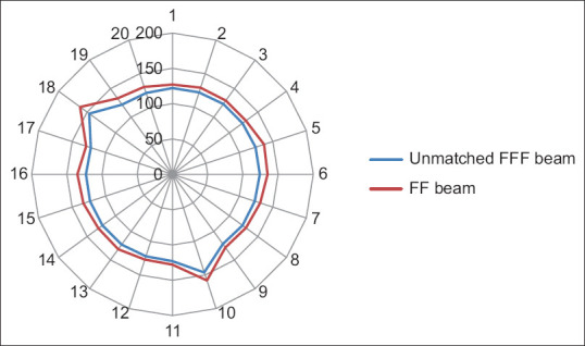
Yan et al. analyzed the dosimetric differences between the flattened and FFF beam plans in terms of TC and dose to OARs for three different anatomical sites. They concluded that both provide equivalent TC, FFF beam provides better OARs sparing. MLC speed is considered a limiting factor for a lower dose rate than the theoretical maximum dose rate in FFF cases especially in lung cases.[9] Xu et al. compared the dose verification between 6X and 6X FFF in intensity-modulated radiation therapy (IMRT) and volumetric-modulated arc therapy (VMAT) and they evaluated the advantages and disadvantages of different radiotherapy plans. No significant difference among dosimetric parameters and plan evaluation indices were been noted for FFF and FF photon beam plans except number of MUs and BOT. FFF beam plans consumed higher MUs with the lesser BOT.[10] Jia et al. investigated the therapeutic role of FFF mode in VMAT compared with FF mode in patients with locally advanced nasopharyngeal carcinoma. They showed that FFF VMAT planning could better protect the OAR surrounding the PTV, including the left and right crystalline lens of the eye.[11] Kumar et al. performed dosimetric analysis for PTV coverage, CI, HI, dose to OARs, ID to normal tissue (NTID), and the total number of MUs. They concluded that the FFFB of 6MV has been found superior in comparison to 10MV for RA planning in case of gynecological malignancies. It offers better HI, CI, and less number of MUs (2.8%) and delivers more NTID (4.3%) for similar target coverage and OAR’s sparing.[12] In the present study, we found that CI, HI, and GI are comparable and their mean values are 0.78 and 0.74, 0.08 and 0.11, and 3.85 and 3.87, respectively, in both 6MV-FFF and 6MV-FF beam cases. MU is higher ([638.31 ± 80.44 vs. 498.00 ± 36.75] [P < 0.001]) due to the softening of the rays, while BOT is lesser ([125.00 ± 07.22 vs. 133.50 ± 09.50] [P = 0.003]) in case of FFF beam. Figures 4-8 show CI, HI, GI, MU distribution, and BOT comparison between 6MV-FFF and 6MV-FF beams.
Figure 4.
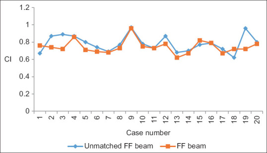
Conformity index comparison between 6 megavoltage-flattening filter-free and 6 megavoltage-flattening filter beams in volumetric arc therapy for head-and-neck cancer
Figure 8.
Beam on time (in Seconds) comparison between 6 megavoltage-flattening filter-free and 6 megavoltage-flattening filter beams in volumetric arc therapy for head-and-neck cancer, where 1-20 represents number of patients and 0-200 represents beam on time (in Seconds)
Figure 5.
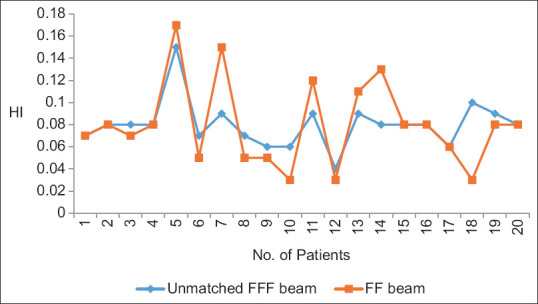
Homogeneity index between 6 megavoltage-flattening filter-free and 6 megavoltage-flattening filter beams in volumetric arc therapy for head-and-neck cancer
Figure 6.
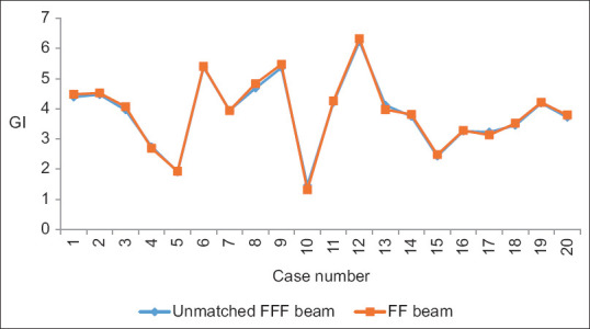
Gradient index comparison between 6 megavoltage-flattening filter-free and 6megavoltage-flattening filter beams in volumetric arc therapy for head-and-neck cancer
Figure 7.
Monitor unit distribution comparison between 6 megavoltage-flattening filter-free and 6 megavoltage-flattening filter beams in volumetric arc therapy for head-and-neck cancer, where 1-20 represents number of patients and 0-800 represents number of monitor units
Surface dose in the case of FFF beam is of great interest from the clinical point of view. SD depends on the magnitude and relative contributions from contamination electrons, low-energy photons, and backscattered radiation. It is logical to remove the FF which is responsible for the majority of contamination electrons reaching the patient surface. Although VMAT plans are optimized for appropriate tumor coverage and as low as a reasonable achievable approach to OARs, 6MV FFF beam plans have higher SD as compared to 6MV FF beam plans (P = 0.52). It can be advantageous in clinical cases where more doses to the surface are required. Figure 9 shows a SD comparison between 6MV-FFF and 6MV-FF beams.
Figure 9.

Skin dose comparison between 6 megavoltage-flattening filter-free and 6 megavoltage-flattening filter beams in volumetric arc therapy for head-and-neck cancer
Ji et al. (2022) evaluated and investigated the feasibility of FFF beams for whole-brain radiotherapy with hippocampus sparing. They evaluated the parameters of the target and OAR for FF and FFF beam and concluded that the differences between the plan modulation index and the gamma index are negligible.[13] Saroj et al. investigated about quality of IMRT treatment plans for esophageal cancer with and without an FF photon beam. They concluded that in contrast to the FF photon beam, a filtered photon beam-oriented IMRT plan provides significant OAR sparing without losing the quality of the treatment plan. Moreover, high MUs, low ID, and BOT are major highlights of the IMRT plan with FFF beam.[14] In the present study, comparable IDs are found in both FFF and FF beams, except for the rest right parotid (P = 0.02). It concludes a decreased risk of secondary cancer, as studies reported that ID is directly associated with secondary malignancy. However, on the other hand, the case of 6MV-FFF plans has a higher number of MUs as compared to 6MV-FF plans (P ≤ 0.001), whereas studies reported that for matched FFF beam number of MUs is lesser.
CONCLUSION
6MV FFF beam provides comparable target coverage and improved dose-sparing effect to most of the OARs. 6MV FFF beam proves to be efficient from the point of view of reduction in the BOT, but on the other hand number of MUs is higher as compared to 6MV-FF plans. With more increase in dose rate, the BOT can be further reduced. In summary, patients treated on HalcyonTM with unmatched 6MV FFF beam plans are equally comparable to the 6MV FF beam plan on TruebeamTM.
Financial support and sponsorship
Nil.
Conflicts of interest
There are no conflicts of interest.
REFERENCES
- 1.Shah SB, Sharma S, D’Cruz AK. Head and neck oncology: The Indian scenario. South Asian J Cancer. 2016;5:104–5. doi: 10.4103/2278-330X.187572. [DOI] [PMC free article] [PubMed] [Google Scholar]
- 2.Singh M, Prasad CP, Singh TD, Kumar L. Cancer research in India: Challenges &opportunities. Indian J Med Res. 2018;148:362–5. doi: 10.4103/ijmr.IJMR_1711_18. [DOI] [PMC free article] [PubMed] [Google Scholar]
- 3.Sharma SD. Unflattened photon beams from the standard flattening filter free accelerators for radiotherapy: Advantages, limitations and challenges. J Med Phys. 2011;36:123–5. doi: 10.4103/0971-6203.83464. [DOI] [PMC free article] [PubMed] [Google Scholar]
- 4.Cashmore J. The characterization of unflattened photon beams from a 6 MV linear accelerator. Phys Med Biol. 2008;53:1933–46. doi: 10.1088/0031-9155/53/7/009. [DOI] [PubMed] [Google Scholar]
- 5.Hall EJ, Wuu CS. Radiation-induced second cancers: The impact of 3D-CRT and IMRT. Int J Radiat Oncol Biol Phys. 2003;56:83–8. doi: 10.1016/s0360-3016(03)00073-7. [DOI] [PubMed] [Google Scholar]
- 6.Aoyama H, Westerly DC, Mackie TR, Olivera GH, Bentzen SM, Patel RR, et al. Integral radiation dose to normal structures with conformal external beam radiation. Int J Radiat Oncol Biol Phys. 2006;64:962–7. doi: 10.1016/j.ijrobp.2005.11.005. [DOI] [PubMed] [Google Scholar]
- 7.Gasic D, Ohlhues L, Brodin NP, Fog LS, Pommer T, Bangsgaard JP, et al. Atreatment planning and delivery comparison of volumetric modulated arc therapy with or without flattening filter for gliomas, brain metastases, prostate, head/neck and early stage lung cancer. Acta Oncol. 2014;53:1005–11. doi: 10.3109/0284186X.2014.925578. [DOI] [PubMed] [Google Scholar]
- 8.Dalaryd M. Dosimetric Effects of Removing the Flattening Filter in Radiotherapy Treatment Units. [Doctoral Thesis (Compilation), Medical Radiation Physics, Lund]. Department of Medical Radiation Physics, Clinical Sciences, Lund, Lund University. 2015 [Google Scholar]
- 9.Yan Y, Yadav P, Bassetti M, Du K, Saenz D, Harari P, et al. Dosimetric differences in flattened and flattening filter-free beam treatment plans. J Med Phys. 2016;41:92–9. doi: 10.4103/0971-6203.181636. [DOI] [PMC free article] [PubMed] [Google Scholar]
- 10.Xu D, Jia F, Li G, Li H. Dosimetric comparison of intensity-modulated radiation therapy and volumetric-modulated arc therapy plans for the treatment of glioma using flattening filter-free and flattening filter modes. Oncol Lett. 2017;13:3451–6. doi: 10.3892/ol.2017.5883. [DOI] [PMC free article] [PubMed] [Google Scholar]
- 11.Jia F, Xu D, Yue H, Wu H, Li G. Comparison of flattening filter and flattening filter-free volumetric modulated arc radiotherapy in patients with locally advanced nasopharyngeal carcinoma. Med Sci Monit. 2018;24:8500–5. doi: 10.12659/MSM.910218. [DOI] [PMC free article] [PubMed] [Google Scholar]
- 12.Kumar L, Kishore V, Bhushan M, Yadav G, Dewan A, Kumar P, et al. Impact of flattening filter free photon beam on rapidarc radiotherapy for gynecologial malignancies: Acomparative study. Iran J Med Phys. 2020;18:23–9. [doi: 10.22038/IJMP.2020.43068.1650] [Google Scholar]
- 13.Ji T, Sun L, Cai F, Li G. Comparison between flattening filter-free (FFF) and flattened photon beam VMAT plans for the whole brain radiotherapy (WBRT) with hippocampus sparing. Asia Pac J Clin Oncol. 2022;18:e263–7. doi: 10.1111/ajco.13624. [DOI] [PMC free article] [PubMed] [Google Scholar]
- 14.Saroj DK, Yadav S, Paliwal N, Haldar S, Jagtap A, Kumar A. Assessment of treatment plan quality between flattening filter and flattening filter free photon beam for carcinoma of the esophagus with IMRT technique. J Biomed Phys Eng. 2023;13:227–38. doi: 10.31661/jbpe.v0i0.2108-1381. [DOI] [PMC free article] [PubMed] [Google Scholar]