

Abstract

Gasification is an advanced thermochemical process that converts carbonaceous feedstock into syngas, a mixture of hydrogen, carbon monoxide, and other gases. However, the presence of tar in syngas, which is composed of higher molecular weight aromatic hydrocarbons, poses significant challenges for the downstream utilization of syngas. This Review offers a comprehensive overview of tar from gasification, encompassing gasifier chemistry and configuration that notably impact tar formation during gasification. It explores the concentration and composition of tar in the syngas and the purity of syngas required for the applications. Various tar removal methods are discussed, including mechanical, chemical/catalytic, and plasma technologies. The Review provides insights into the strengths, limitations, and challenges associated with each tar removal method. It also highlights the importance of integrating multiple techniques to enhance the tar removal efficiency and syngas quality. The selection of an appropriate tar removal strategy depends on factors such as tar composition, gasifier operating and design factors, economic considerations, and the extent of purity required at the downstream application. Future research should focus on developing cleaning strategies that consume less energy and cause a smaller environmental impact.
1. Introduction
Gasification technology offers clean technological intervention to offset fossil energy.1,2 It effectively transforms any carbon/hydrogen-based solid matter3,4 into a combustible gaseous fuel that contains CO, H2, and CH4 as the primary combustibles, providing a fundamental advantage of product and feed stock flexibility. The feedstock includes coal, biomass, waste materials such as municipal solid waste (MSW), sewage sludge, and other waste.3−13 It should be noted that due to the anticipated 70% rapid increase in the global waste generation between the year 2016 and 2050, gasification of waste materials is becoming a key technology interest.10 Apart from thermal applications, the product gas known as “syngas” from gasification can be utilized in various applications, such as fuelling an internal combustion (IC) engine,14,15 gas turbine,16 and integrated gasification combined cycle17−19 for power generation; as a feed for Fischer–Tropsch/Alcohol synthesis reactors, synthetic natural gas, and hydrogen; and in advanced technologies like solid oxide fuel cells.15,19−26 Several reactor configurations are available for gasification, including fixed bed, fluidized bed, entrained bed, and others, each with specific preferences for process conditions. By selecting the appropriate reactor configuration, the required syngas composition and conversion rates can be achieved to meet the specific needs of a particular application. Although syngas can be used in various applications, such as those mentioned earlier, one of the most significant challenges associated with its production is the presence of byproducts known as “tar”. These are condensable higher-hydrocarbon compounds that are produced during the gasification process. Compounds designated as tar can degrade the downstream equipment and applications27 by methods as simple as clogging the flow paths (as in IC engines and turbines) to as critical as poisoning catalytic layers (as in fuel cells and alcohol synthesis processes). As such, syngas must be cleaned to the extent demanded by specific applications to meet the tar permissible limits.28 It should also be noted that, based on the nature of feedstock chemical composition, there are other undesirable vapor-phase products such as halides, ammonia, cyanide, etc.19 that can also affect the performance of downstream applications as well as the syngas cleaning and tar removal. A more comprehensive review on impurities other than tar can be found in the literature,29,30 while this Review focuses mainly on tar compounds formed in the gasification process.
It is important to note that tar formation forms a part of the fundamental thermochemistry of gasification, and as such the presence of tar in syngas is inevitable. The amount of tar in the syngas is affected by both the gasifier configuration and the operating conditions. Therefore, reducing tar in raw gas is a key area of research and development in the gasification process.31 Irrespective of the attempts to reduce the tar content within the gasifier itself by in situ methods, the literature reports the tar content in the raw syngas to be well above the permissible limits posed by the applications.32−35 Hence, ex situ tar destruction or conversion, i.e., treating the gas after coming out of the gasifier, becomes critical.36 Literature reports on the adoption of several methods of ex situ tar destruction, such as the separation of tar compounds by filters, electrostatic precipitators, and cooling the product stream using scrubbers and spray towers.37 In recent times, raw syngas cleaning has been attempted using plasma technology, particularly by using nonthermal plasma or low-temperature plasma, which is known for allowing thermodynamically unfavorable chemical reactions even at ambient conditions and thereby seems promising for energy-efficient chemical conversion.3839−41 Nonthermal plasma is a soup of reactive species, including electrons, ions, radicals, metastable, excited neutrals, ground-state neutrals, and radiation. These species can dissociate and further reform the stable compounds like “tar” generated in gasification.
This Review provides a holistic review of gasification tar and existing methods available to ensure that the product gas contains tar in permissible limits so that the gas can be used in applications without any issues. The Review is divided into four sections. A brief introduction is presented in this section, followed by a summary of gasification technology in section 2. Section 3 provides a detailed discussion of the formation, evolution, and nature of tar. Section 4 discusses the cleaning technologies to remove or reduce tar in product gas.
2. Gasification Technology
Gasification is a substochiometric thermochemical conversion process carried out in a reactor termed as “gasifier” wherein solid carbonaceous matter (CM) like biomass (∼C1.0H1.4O0.6), coal (∼C11.0H1.0O1.4), municipal solid waste (MSW) (∼C100H250O80N), refuse-derived fuel (RDF) (∼CH1.569O0.541) etc., is converted predominantly to a gaseous mixture of combustible compounds (H2, CO, and CH4), incombustible compounds (CO2 and N2), a trace quantity of condensable higher hydrocarbons known as “tar”, and compounds like NH3, HCN, H2S, etc. Char and ash are the solid-phase byproducts, and the exact composition of the gas phase is process-specific with a dependence on the gasifying media, i.e., air, oxygen, and/or oxygen–steam. Figure 1 shows the routes of formation of these combustible products and byproducts. It can be seen from Figure 1 that these compounds or products are formed from the moisture, volatile matter, and fixed carbon contents of CM, which go through various stages of thermochemical conversion. Before the reactor/gasifier configurations are discussed, the chemistry of gasification, which is facilitated in different gasifier types, is discussed first.
Figure 1.

Route map of biomass and wastewater conversion into products through gasification.
2.1. Gasification Chemistry
For the sake of explaining the gasification chemistry, consider a reactor/downdraft gasifier, i.e., a vertical cylinder where the flow direction of both product gas and carbonaceous matter (CM) is downward, as can be seen in Figure 2a. The CM is fed into the reactor from the top, which forms a bed in the reactor. The feed rate and the bed height are governed by the gasifier geometry. The gasifying media42−45 (air, steam, and oxygen) are supplied at various heights of the reactor far from the top, where the solid feed is initially ignited. Typically, air is used as the gasifying medium. Concurrently, research is also being reported on the use of a mixture of steam and oxygen (oxygen–steam gasification),46−48 and oxygen-enriched air49−52 as gasifying media. Chemical looping gasification is another novel approach that replaces the gasifying gas medium with oxygen-carrying solids acting as intermediary materials in chemical reactions by releasing or capture the lattice oxygen.53−56 The supply of gasifying media to the gasifier creates a combustion zone locally. With the local availability of a continuous supply of oxidizing media, this zone facilitates the combustion of CM. The flame sets up a temperature gradient across the bed height, marking different zones without any distinct separation as (1) drying, (2) pyrolysis, (3) oxidation, and (4) reduction.
Figure 2.

Gasifier configurations: (a) downdraft, (b) updraft, and (c) fluidized bed gasifier. (d) Picture of condensed tar stuck to the downstream component of a gasifier at Indian Institute of Science.
The temperature profile along the height of a gasifier plays a crucial role in determining the nature of the chemical reactions or processes that occur in each zone. Different temperature zones within the gasifier are required to achieve specific reactions, and the temperature profile must be carefully controlled to optimize the gasification process. (1) In the drying zone, which is typically seen near the CM feed ports, the temperature can go up to about 473 K, and the feed material mostly loses moisture in this zone.57 (2) Once the temperature of CM reaches 623–673 K, the release of volatiles begins, and simultaneously, over a certain residence time, CM becomes transformed into char. (3) The released volatiles undergo subsequent reactions downstream, controlled by the local bed temperature and availability of gasifying medium, and form primary oxygenates and gases like CO, CO2, and H2O wherever combustion is favored. (4) These products further react with the hot char to generate noncondensable gases, and simultaneously the gases react among themselves through reforming and shift reactions, generating CO, CO2, H2, CH4, and complex polymerized compounds. The reactions favored in the presence of hot char “C” are gasification reactions, which are represented as reactions R1–R3. The Reactions R1 and R2 are considered principal gasification reactions, which are endothermic.
| R1 |
| R2 |
| R3 |
It is important to note that the endothermic reactions in a gasifier are supported by heat generated in the combustion zone. The heat generated in the combustion zone provides the energy necessary to drive the gasification reactions and sustain the gasification process. Hence, gasification is fundamentally an autothermal process. It should be noted that the tar formation is a persistent byproduct of gasification, which evolves during the pyrolysis stage as primary oxygenates and matures into aromatic hydrocarbons that react with other gases and moisture as described earlier. Reaction R4 shows the water gas shift reaction, and reaction R5 shows the global gasification reaction.
| R4 |
| R5 |
2.2. Gasifier Configurations
Configuration of gasifiers can be broadly classified into three types, namely, fixed bed, fluidized bed, and entrained flow. In fixed bed gasifiers like the one mentioned in section 2.1, the feed CM is fed at the top, creating a bed of CM that is supported on a grate/screw system placed at the bottom of the gasifier. The feed CM moves with the plug profile during the gasification process, facilitated by the moving grate/screw system. Updraft and downdraft fixed bed systems are the most commonly seen, as shown in Figure 2a and b, respectively. In downdraft systems, the feed and gas move cocurrently, and the product gas leaves from the bottom of the reactor, passing through the zone near the grate of fire. In updraft systems, the movement of feed is countercurrent to the gas, with product gas leaving from the top. It should be noted that because of the exit of product gas at the top, the combustion and reduction zones are swapped, with the bottom-most zone being the combustion zone in the updraft, unlike the reduction zone in the downdraft gasifier. Figure 2c shows fluidized bed gasifiers, wherein the feed particles are suspended in the gasifying medium, resulting in the bed acting like a fluid. Thorough mixing between the gasifying medium and feed results in a uniform temperature profile and facilitates the gasification chemistry. Hot inert solids, such as sand, limestone, dolomite, etc., are suspended in contact with the CM feed to support drying and pyrolysis. In entrained flow gasifiers, the gas and the feed (mostly coal) are fed together (cocurrent) at a very high velocity into the reactor from the side or top. Sometimes, entrained flow gasifiers can be viewed as plug flow reactors having CM and a gasifying medium as inputs at one end and the product gas at the other end. Oxygen is the most used gasifying medium, and the combustion can happen right at the entry point on one end; the typical composition of the product gas and its energy value expected from these gasifier configurations in the presence of various gasifying media are consolidated and reported in Table 1. The influence of the factors shown in Table 1, such as feed stock, gasifying medium, and temperature, is discussed in detail in section 3.2.
Table 1. Product Gas Composition in Different Oxidizing Media.
| gas composition (vol %) |
|||||||||||
|---|---|---|---|---|---|---|---|---|---|---|---|
| feed | oxidizing/gasifying medium | ER | SBR | H2 | CO | CO2 | CH4 | N2 | C2H4 | LHV (MJ/Nm3) | ref |
| fixed bed gasifiers | |||||||||||
| biomass pellet wood | air | 9–10 | 12–15 | 14–17 | 2–4 | 56–59 | 3–6 | (58) | |||
| dry casuarina wood | oxygen + steam | 0.18 | 1 | 45–51 | 13–25 | 15–28 | 1–4 | 0 | 7–10 | (31, 57) | |
| pellet wood | oxygen + steam | 0.3 | 2.5 | 52 | 13 | 32 | 3 | 0 | 8.3 | (47) | |
| rice straw | air | 6 | 10 | 63 | 14 | 3 | 5.62 | (59) | |||
| palm oil wastes | steam | 0.5–2 | 35–60 | 12–33 | 14–26 | 3–12 | 2 | 9–14 | (60) | ||
| olive kernel | air | 0.14 | 20–30 | 15–20 | 40–55 | 10–12 | 9–10.4 | (61) | |||
| RDF | air | 7.17 | 19.71 | 14.45 | 1.76 | 3.9 | (62) | ||||
| sewage sludge + woody biomass | air | 4.5 | 15 | 17 | 1.5 | 1–2 | 5.5 | (63) | |||
| sewage sludge + residue from hydrolysis | air | 0.2–0.3 | 11.6 | 16.7 | 17.6 | 5.94 | 6.42 | (64) | |||
| fluidized bed gasifiers | |||||||||||
| pellet wood | steam/air | 0.8 | 9–38 | 15–32 | 16–17 | 4–14 | 0–53 | 3.5–14.4 | (65, 66) | ||
| empty fruit bunch | air | 0.2–0.4 | 10.27–38 | 22–36.4 | 10–65 | 6–15 | 8–16 | (67) | |||
| pine sawdust | oxygen + steam/steam | 0.2 | 1.6–2.7 | 21–39 | 15–43 | 15–25 | 5–7 | 7.4–9 | (68, 69) | ||
| silica sand | air | 0.4 | 7–8.2 | 24–31 | 59–63 | 4–5 | 1.6–1.9 | (70) | |||
| empty fruit bunch | air | 0.15 | 18.4–27.4 | 32–45 | 17–36 | 10–12 | 12.4–15.4 | (67) | |||
| bamboo | air | 0.4 | 3.2–9.1 | 21.4–32 | 60–80 | (70) | |||||
| sewage sludge + coal | air | 7–27 | 9–11 | 12–15 | 1–4 | 46.19 | 2–6 | (71, 72) | |||
| pine chips + coal | air/steam | 13.05 | 16.81 | 8.39 | 1.63 | 59.13 | 4.29 | (73) | |||
| MSW + pine dust | air | 0.5–0.2 | 9–11 | 17–19 | 15–19 | 4–6 | 5.3 | (74) | |||
| MSW + switchgrass | air | 10 | 14.1 | 15–18 | 2–4 | 6.7 | (75) | ||||
| beechwood + polyethylene | steam | 37.1 | 23.6 | 8.7 | (76) | ||||||
| entrained flow gasifiers | |||||||||||
| pellet wood | air | 0.28 | 7.6 | 26 | 10 | 3.3 | 52 | 1.1 | 6 | (77) | |
3. Tar from Gasification
As mentioned earlier, tar from gasification is a persistent byproduct that is neither in large amounts for beneficial use nor small enough amounts to be ignored.42 The tar consists of a mixture of compounds that are largely aromatic, having molecular weights heavier than that of benzene.78 Tar compounds form fine droplets of size <1 μm like a mist and can agglomerate into large droplets that can condense over a wide range of temperatures, much higher than the ambient temperature. They also are known to coat the solid particles78 and stick to the surfaces, causing fouling, corrosion, and blockage in downstream passages and equipment. Figure 2d shows a picture of condensed tar sticking to the flange surface, having a typical appearance, i.e., thick, viscous liquid-brownish to deep black color;78 tar is also known to have a pungent smell.78 Regardless of the amount and composition of the tar formed, handling it is a universal challenge of gasification systems.79 The concentration and composition of tar formed are strongly dependent on various factors such as (1) temperature, (2) gasifier design (downdraft/updraft/fluidized bed), (3) gasification medium, (4) feed stock, (5) residence time, and (6) pressure.33 Hence, the effect of these factors on tar formation has been studied by various researchers over many decades.80−93 While few researchers have focused on developing new approaches to quantify tar formation, others have attempted to compare available methods to identify and quantifying the tar formed from gasification,94−100 which itself is very complex and tricky.
3.1. Classification of Tar
Researchers have classified or grouped tar compounds in many ways.58 One way is to classify the tar compounds into primary, secondary, and tertiary classes58 based on the functional group(s) that make up the tar. Figure 3 shows the functional groups of the tar compounds that represent one of these three classes. As can be seen in Figure 3, the classification is based on the temperature gradient in the gasifier bed (presence of thermal or partial-oxidation regimes in the gasifier58), due to which the released oxygenates go through various reactions such as chemolysis, depolymerization, oxidation, polymerization, and cycloaddition,31 evolving into polynuclear aromatic hydrocarbons (PAHs).58 Based on the residence time available in distinct temperature zones/regimes, the proportion/presence of these three classes of tar will vary, spanning over a range of temperatures.101 The tar maturation is well connected to the gasifier zones presented in section 2.2.
Figure 3.
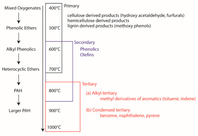
Maturation and temperature ranges of tar classes.
In another way, tar is classified into five classes distinguishing different properties of tar compounds such as molecular weight, condensation behavior and water solubility/polarity,31 as shown in Table 2.31,102Figure 4 shows that the dew point of tar compounds belongs to either of these five classes. It is interesting to note that, excluding class 1, the dew point of the tar compounds of classes 2–5 varies with the concentration of the individual class of tar compounds, as shown in Figure 4. The importance of the dew point at a given concentration of these tar class compounds will be emphasized in the discussion presented in section 3.3.
Table 2. Tar Compound Classification Is Based on Solubility, Condensability, And Chemical Composition.
| tar class | class name | property | representative compounds |
|---|---|---|---|
| 1 | gas chromatography (GC)-undetectable | very heavy tars cannot be detected by GC | subtracting GC-detectable tar from total gravimetric tar |
| 2 | heterocyclic aromatics | heteroatoms, highly water-soluble compounds | pyridine, phenol, cresols, quinoline |
| 3 | light aromatic (1 ring) | usually, a light HC with a single ring does not pose a problem regarding condensability and solubility | toluene, ethylbenzene, xylenes, styrene |
| 4 | light PAH (2–3 rings) | two- and three-ring compounds condense at low temperatures, even at very low concentrations | indene, naphthalene, biphenyl, fluorene, anthracene |
| 5 | heavy PAH (4–7 rings) | larger than three-ring, these components condense at high temperatures at low concentrations | fluoranthene, pyrene, chrysene, perylene, coronene |
Figure 4.

Tar concentration of different classes as a function of dew point temperatures: class 2 (□), class 3 (▲), class 4 (●), and class 5 (◆).
3.2. Concentration and Composition of Tar
Tar concentration is generally expressed in terms of the total mass of tar compounds present in a unit volume of the product stream, i.e., g/Nm3 or mg/Nm3. Sometimes it is also expressed as a mass fraction of the dry CM feed or as ppm, as mentioned earlier; the amount/concentration/yield of tar depends on several factors, out of which the choice of gasifier type inherently decides the tar yield. Factors/operating conditions such as feed, gasification temperature, gasification agent, residence time, equivalence ratio, steam-to-biomass ratio, and pressure can also affect tar yield and composition. It is to be noted that there is no single factor independently affecting the evolution of tar, but all of these factors are highly coupled with one another. The composition and yield of tar are based on the combination of the operating conditions of these factors. Table S1 of the Supporting Information shows typical tar levels reported in the literature for various operating conditions.
3.2.1. Gasifier Type
Figure 5 shows a box plot of tar concentrations reported in the literature for various gasifier types, and Table 3 compares the minima/maxima reported in Figure 5 with the typical tar levels reported in literature.31 As can be observed from Figure 5 and Table 3, the downdraft gasifier gives a low tar yield, as the product gas stream exits the gasifier through a temperature zone favoring tar cracking. Although typical residence time is not reported as such in the literature, an increase in residence time reduces the primary and secondary tar content, with a slight increase in the amount of PAHs (>3 rings). However, a down-draft gasifier is appropriate for smaller units limited to a thermal input of 10 MWth. This is equivalent to 2.4 tonnes/h of feed having a lower calorific value (LCV) of 15 MJ/kg. Thus, for larger feed operations, using a fluidized bed is necessary to achieve uniform temperature distribution over the bed; handling large amounts of tar becomes necessary.
Figure 5.

Box plot of tar concentrations for the various gasifier types.
Table 3. Tar Formation Expected in a Range from Various Gasifier Types.
3.2.2. Gasification Temperature
Gasification temperature is another important factor that is inversely related to the tar yield. That is, higher gasification temperatures yield low tar. However, at high gasification temperatures, i.e., above 1123 K, the formation of class 4 and class 5 tar compounds is known to dominate, as shown in Table 2.103 The literature suggests that, for a fluidized bed gasifier, increasing the gasification temperature from 1023 to 1053 K reduces the tar yield from 180 to 40 g/Nm3 in the presence of steam as the gasifying medium.104 However, to achieve considerable carbon conversion in the process, at least 1023 K is required irrespective of the values of the other operating parameters. It should also be noted that, as can be seen in Figure 2a and b, the product gas exits by passing the combustion zone, while in an updraft system the gas passes through the drying zone. Because of this, the tar cracking reactions occur in the product gas before the exit in the downdraft system, which reduces the tar content. In general, assuming other operating conditions are the same, the tar yield will be less in the downdraft system than in the updraft system. Typically, the gasifier temperature varies in the range of 500–1150 K in the literature data summarized in Table S1.
3.2.3. Feed Type
Figure 6 shows the effect of wood, waste (RDF/MSW), and agroresidue on the tar concentration for air as a gasifying medium. As can be seen, the median tar concentration is high for waste compared to that of wood or agroresidue within the gasifier type and is higher for a fluidized bed than for downdraft gasification of waste. Figure 7 shows the effect of the feed CM, gasification temperature, and other parameters, including the tar content. In the case of agrofuels and RDF, gasification temperatures are restricted to the lower range (below 1173 K) to avoid sintering issues. This optimal gasification temperature range, as shown in Figure 7, is also reported in various literature works.103,105 Even though higher gasification temperature reduces tar content, allowing longer residence time for cracking reactions will compromise the gas heating value and risk a rapid increase in the formation of three- or four-ring PAHs.103 Typically, the cellulose and hemicellulose contents of the biomass are associated with the gas yield, and lignin is associated with the tar yield. High amounts of lignin lead to high tar yield.106 Based on Table 1 and from the literature,106 there is no trend observed for the effect of biomass type on the tar content, which is reported to be more affected by other factors such as reactor type and operating conditions, including gasification temperature, gasifying medium, etc., then the biomass type.106 Experimental conditions should be fixed to confirm this observation further, and only the biomass type should be varied.
Figure 6.

Box plot showing the effect of wood, waste (RDF/MSW), and agroresidue on the tar concentration for air as a gasifying medium.
Figure 7.

Typical gasification temperature for various feedstocks and its influence on a few parameters.
3.2.4. Gasifying Medium
Typically, a low equivalence ratio is maintained in the gasification zone to avoid lowering the gas heating value. However, the availability of oxygen for volatiles can stop the maturation of primary tars over time, thereby reducing the tar content (the equivalence ratio (φ, ER) is a parameter used in combustion engineering to describe the ratio of the actual fuel/air ratio to the stoichiometric fuel/air ratio required for complete combustion of a fuel). At higher ER, formation of PAHs (four- or five-ring) is known to increase.33 This effect of the equivalence ratio becomes significant at a very high gasification temperature. The effect of oxygen on reducing the tar content can also be realized by using steam as a gasifying medium. However, careful selection of the steam to biomass ratio is important to avoid compromising on gas quality.33 The addition of oxygen to steam (oxygen–steam) further reduces the tar yield to the lowest value. For a biomass–RDF mix, Catarina et al.107 observed very little effect of the ER on tar composition at a gasification temperature of 800 °C, an expected behavior since the main tar components are already PAHs; this observation is opposite that of Mastellone et al.108 It should be noted that the presence of these PAHs makes the tar more toxic due to its hydrophobic, persistent, and genotoxic nature.
The typical (expected) compositions of tar compounds from the gasification process are shown in Table 4.33 It is evident from the data that 85% of tar composition by weight consists of class 2, 3, and 4 tar compounds, and 66% of total tar composition is made up of specific compounds, namely, benzene, phenol, toluene, and naphthalene, out of which nearly 40% is benzene. It should be noted that though benzene is not classified as a tar compound, it is detected, quantified, and reported in the literature.109−117
Table 4. Typical Tar Composition from Gasificationa.
| tar compound | typical composition by weight (%) | tar class |
|---|---|---|
| benzene | 37.9 | 3 |
| toluene | 14.3 | 3 |
| other one-ring aromatic HC | 13.9 | 3 |
| naphthalene | 9.6 | 4 |
| other two-ring aromatic HC | 7.8 | 4 |
| three-ring aromatic HC | 3.6 | 4 |
| four-ring aromatic HC | 0.8 | 5 |
| phenolic | 4.6 | 2 |
| heterocyclic | 6.5 | 2 |
| others | 1 |
Note: benzene is not usually classified as a tar compound, and only compounds having a molecular weight greater than that of benzene are considered as tar. Statistical information was not found, and only typical values were available in the literature.
3.3. Permissible Tar Limits in Syngas for Various Applications
It can be seen from Figure 4 that the dew point at which the tar compounds of a particular class condense varies with the concentration. This means that a tar compound of class 2, as defined in Table 2, condenses at ≈323 K if it is concentration is about 1 mg/Nm3; however, if the same class compound is present in a large concentration, which is about 10000 mg/Nm3, it will start to condense even at temperatures >373 K. Hence, understanding the dew points of different tar classes at different concentration is important to decide the amount of cleaning required to achieve the desired gas quality. This means that by reducing the concentration of tar in the product gas, the temperature at which they condense, i.e., the dew point of the tar compound, is lowered. If the dew point is lowered below the operating temperature of the application or preferably much below the ambient temperature, the condensation of tar leading to clogging can be avoided.
It can be inferred from Figure 4 that the class 5 tar compounds such as pyrene, i.e., heavy PAHs, are very critical in cleaning, as they can condense at a very high temperature, i.e., > 423 K, even if they are present in small concentrations of about 0.1 mg/Nm3. It is also to be noted that these heavy PAHs are the precursors of soot.58 On the other hand, class 3 compounds, which are light aromatics such as benzene and toluene, seem to not condense at ambient temperatures and higher, even if their concentration is as high as about 10000 mg/Nm3. However, removing these compounds is necessary,102 since BTEX (benzene, toluene, ethylbenzene, and xylene) compounds are classified as priority pollutants and are considered as inhibitory compounds in FT synthesis.78 Based on Table 4 and Figure 4, compounds that represent 33% of the tar formed can condense between 323 and 573 K if their concentration exceeds 1 mg/Nm3.
Figure 8 shows the tolerance level of tar concentration for several applications,19 which implies that a higher gas purity level is required moving from applications such as IC engines (tar permissible limit of 100 mg/Nm3) to FT/methanol synthesis (tar permissible limit of 0.1 mg/Nm3).
Figure 8.

Tar tolerance limits for downstream applications of a gasifier.
4. Tar Destruction/Removal: Existing Technologies
Measures for abatement or mitigation of tar can be broadly classified into primary (within the gasifier, in situ) and secondary (outside the gasifier, ex-situ).27,36 Even though primary measures are the ideal approach for tar mitigation, it may not always be possible to completely achieve the desired tar levels for applications, as shown in Figure 8, without negatively impacting the quality of the gas, leading to a decrease in cold gas efficiency. In some cases, this may also result in complex gasifier construction, and achieving low tar levels might require a trade-off between gas quality and cold gas efficiency. Hence, a combination of in situ and ex situ measures is very effective to meet the gas purity standards. The following section will discuss the secondary measures for gas cleaning, which can be further classified into (1) physical or mechanical methods, (2) chemical methods, and (3) nonthermal plasma methods.
-
1.
Physical or mechanical methods involve the separation of tar compounds from the product gas and are used either directly on raw gas coming at a temperature >673 K (hot gas cleaning) or after cooling the raw gas to a temperature between 293 and 333 K (wet gas cleaning).36 Hot gas cleaning prevents loss of heating value of the gas with minimal byproduct formation, whereas cold gas cleaning systems are much cheaper and effective with the loss of sensible heat.31
-
2.
Chemical methods involve the reformation or cracking of the tar compounds into useful gaseous compounds using a catalyst, heat, and/or steam.118
-
3.
Nonthermal plasma methods involve technology approaches like thermal/catalytic cracking, where instead of physical separation of unwanted compounds from the gas stream, cracking or reforming of condensable vapors to noncondensable gases is carried out.119−128
4.1. Mechanical or Physical Gas Cleaning Systems
Table 5 shows various hot and wet gas cleaning equipment whose working principles and other details are available in the literature.36,78,102,129−133 Though physical cleaning systems are designed primarily to capture particulate matter from the product gas, they are also efficient for tar removal. This is possible because tars, while condensing at temperatures below 723.15 K, form aerosols heavier than vapors and can be removed by physical forces similar to removing particulate matter.103Table 6 shows the typical separation efficiencies reported in the literature for some of these systems.133 As can be observed from Table 6, the separation efficiencies of these systems are not 100%; hence, depending on the type of removal system, multistage cleaning might be required, which adds to the cost of operation and maintenance. Though hot gas cleaning prevents the loss of energy value of the product gas, wet/dry gas cooling/scrubbing is the highly recommended method, since cooling gas is very effective to bring down the tar’s dew point. Typically, chiller water is used in gas cooling, which also scrubs the gas of particulate matter and tar compounds. Instead of water, organic scrubbing liquids are also used in a technology named OLGA technology.134Figure 9 shows a performance comparison of OLGA with other conventional technologies such as wet scrubber and wet ESP.134,135 OLGA shows promising results, achieving removal efficiencies of >99% for all the classes of tar, whereas the ESP and wet scrubbers show selective performance of tar removal based on their classes, achieving efficiency mostly in the range of 50–75%.
Table 5. Mechanical/Physical Gas Cleaning Systems.
| method | equipment |
|---|---|
| hot or dry gas cleaning | cyclone, rotating particle separators (RPS), electrostatic precipitators (ESP), filters (bag/baffle/ceramic/fabric/tube/sand bed), absorbers, etc. |
| cold or wet gas cleaning | spray towers, packed column scrubbers (wash tower), scrubbers (impingement/venturi), wet ESP, OLGA, wet cyclones, etc. |
Table 6. Tar Reduction Efficiency and Operating Temperature in Various Gas Cleaning Systems.
| temperature (K) | tar reduction (%) | |
|---|---|---|
| sand bed filter | 283–293 | 50–97 |
| wash tower | 323–333 | 10–25 |
| venturi scrubber | 50–90 | |
| wet ESP | 313–323 | 0–60 |
| fabric filter | 403 | 0–50 |
| RPS | 403 | 30–70 |
Figure 9.

Comparison of the tar removal performance of scrubber, ESP, and OLGA: heavy tar (black bar), light tar (red bar), heterocyclic (orange), and dew point (●).
Although the physical separation process (like scrubbers) plays a significant role in tar removal from product gas, as predicted by Milne et al.58 in 1998, the carcinogenic/hazardous tar is transferred into the scrubbing phase (water, oil, etc.) during the tar removal process, and the contaminated phase should be treated before disposal, keeping environmental concerns as a high priority. The recycling and reuse of these waste streams are reported to be complex, involving the separation of tar and contaminants from water.
The utilization of mechanical methods for the removal of tar from gasification processes faces certain limitations. These methods, such as filtration, condensation, and cyclones, encounter challenges when it comes to effectively removing fine tar particles and maintaining the overall efficiency of the system. Mechanical equipment used for tar removal, such as filters or scrubbers, can be prone to fouling and clogging. Tar deposits can accumulate on surfaces, reducing the efficiency of the equipment and necessitating frequent maintenance or cleaning. This can result in downtime and increased operational costs. Gasification processes often involve high temperatures, corrosive environments, and high-pressure conditions. These conditions can pose challenges for mechanical equipment and materials, as they may lead to corrosion, erosion, and mechanical failure. Specialized materials and designs may be required to handle these conditions effectively. These methods often require energy input to operate pumps, fans, or other equipment involved in tar removal. This energy consumption adds to the overall energy demands of the gasification process and can impact the efficiency and economics of the system. A concurrent summary of typical gas cleaning systems employed in an industrial scale gasifier, their tar removal efficiencies (in %), and concentration of tar left over is presented in section 4.2.3.
4.2. Chemical Methods of Gas Cleaning
4.2.1. Thermal and Steam Cracking
In thermal cracking, tar is converted into lighter gases with the help of oxidizing species at high temperatures, giving them enough residence time. The residence time is inversely related to the cracking temperature. For example, 80% of naphthalene is destructed/cracked in a residence time of 1 s when the cracking temperature is 1423 K, whereas when the temperature is reduced from 1423 to 1273 K the residence time for the same conversion level needs to be increased beyond 12 s;103,13 at same time, by increasing the cracking temperature from 1273 to 1523 K, only 0.5 s of residence time was needed.19,31 Hence, even though thermal cracking is simple conceptually, high process temperatures demand more sophisticated equipment and materials, which increase the cost. Also, very high cracking temperatures in the range of 1373–1573 K are necessary to minimize the reactor’s space. Thermal cracking is known to be economical only when it is used for large-capacity gasifiers.
Thermal cracking is also known for soot formation due to its high operating temperatures, though removing soot by spending additional energy is an option.132 Soot formation can also be minimized through partial oxidation of product gas by adding oxygen or air or sometimes even steam—steam cracking/reforming. This might result in a decreased heating value, as the product gases also get partially oxidized.103 For steam cracking of tar, higher steam-to-carbon molar ratios are required compared to that of industrial hydrocarbon steam reformation.136 It is also reported that steam has a poor influence on the conversion of aromatics58 and yields more phenolic tars, which are easy to reform catalytically.58,137 According to Brandt et al.,138 employing steam cracking followed by charcoal catalysis can achieve a tar yield of as low as 15 mg/Nm3, which is still not enough to meet the purity levels expected by applications such as fuel cells, the FT process, or methanol synthesis, as shown in Figure 8.
Thermal cracking as a method for tar removal from gasification processes also has its limitations. While it can effectively break down tar into simpler compounds through high-temperature reactions, it may face challenges in completely converting complex tar molecules. Additionally, the process requires careful control of the temperature and residence time to avoid potential issues such as coke formation and reactor fouling. Proper design and optimization are crucial to achieving efficient and reliable tar removal using thermal cracking techniques.
4.2.2. Catalytic Cracking
Tar reduction using a catalyst is another promising technique, which can be implemented in two ways:139 one way is integrating the catalyst with the input biomass to eliminate the tar within the gasifier itself (in situ approach), leading to what’s known as catalytic gasification or pyrolysis, and the second way is where tar is removed outside the gasifier in a secondary reactor packed with the catalyst.58,139 Catalysts are effective in cracking tar compounds through reforming, cracking, hydrogenation, and selective oxidation, and many researchers have widely studied their performance over time.27,68,70,115,140−151 Catalytic tar cracking is considered to be promising, as it can be performed at temperatures close to that of gasifier outlet.151 The expectations of a catalyst material for tar cracking are summarized as follows:152
-
1.
Good activity and efficiency in removing tar present in a gas mixture (producer gas)
-
2.
Good stability to deactivation and poisoning
-
3.
Easy regeneration
-
4.
Good abrasive strength
-
5.
Inexpensive and ready availability
-
6.
Less harm to the environment
Although it is also mentioned in the literature that the catalyst should be capable of reforming methane, keeping hydrogen or syngas as the desired product, it should be noted that the volumetric composition of methane is significantly lower than those other species, such as H2, CO, and CO2, in the gasifier product gas.153,154 Typically, the performance of catalytic tar cracking is dependent on the type of catalyst and its composition. A catalyst is composed of a metal (catalytic phase), a promoter (increase the activity or stability of the catalyst), and a support (for dispersion of the active phase). Typically, in the literature,143,146,150,155−157 catalysts for tar reduction are broadly classified, as shown in Figure 10. The compositions of various catalysts with operating conditions that are used for tar reduction are shown in Table 7.
Figure 10.

Catalyst materials for tar cracking.
Table 7. Performance of Catalytic Tar Cracking.
| catalyst | support | operating conditions (°C) | tar cracking (%) | ref |
|---|---|---|---|---|
| Ni | quartz wool | 500–900 | 43.2–100 | (115, 146−148, 158−160) |
| Rh | SiO2 | 550–700 | 100 | (143−145, 161, 162) |
| Pt | CeO2 | 800 | 20–50 | (149) |
| Ru | (PPh3)3Cl2 | 600 | 11.8–80 | (163, 164) |
| FeO | 900 | 100 | (142) | |
| Co and Ni | oxidized Shengli lignite char (OXAWSL) | 450–500 | 76.3 | (165) |
| Ca | waste peat char (activated by CO2 (CPC) and KOH (APC)) | 900 | 94.4 | (166) |
| Ru and Ni | α-Al2O3 | 400–800 | 97.8 | (167) |
| Ni-xSiO2 @C | wood carbon (WC) | 500–650 | 97 | (168) |
| Ni-doped | biochar (BC) | 600 | 60 | (169) |
| Ni–Pt | Ce1-xZrxO2 | 300–600 | 90.4 | (170) |
| Fe–Ni | Al2O3 | 500–700 | 63.8–100 | (171, 172) |
| CaNiRu MnNiRu | α-Al2O3 | 300–900 | 100 | (173) |
| Fe–Ni Cu–Ni | activated carbon | 200 | 99.1 | (174) |
| Ni, Fe, and Mg | zeolite | 800 | 86 | (175) |
| CaO-Ca12Al14O33 | Al2O3 | 600–800 | 73 | (176) |
| Ni/Ru–Mn | α-Al2O3 | 600–1100 | 100 | (177) |
| Pt | CexZr1-X O2/Al2O3 | 700 | 82 | (178) |
| Ni/AC | activated carbon | 500–700 | 99 | (179) |
| biomass porous char | K/Fe | 800 | 94.9 | (180, 181) |
| activated char loaded with nickel | activated char | 600–800 | 80 | (182) |
| biochar | 600–900 | 82–100 | (183−188) |
Nickel is the most widely used catalyst among group VIII for steam/dry reformation, and it is also used for tar cracking.153,154 Two types of Ni-tar cracking studies are reported in the literature: one is the oxidation of tar with O2, and another is the steam reformation of tar. The Ni is oxidized to NiO in the presence of oxygen, which catalyzes the combustion reaction, and Ni prefers a reformation reaction in the absence of O2. It is reported that partial oxidation is better in terms of removal (specifically in fluidized beds) and tar conversion than steam reforming.153 Ni catalysts are reported to be more active for heavier hydrocarbons, which is key to avoid agglomeration of soot, and improves the H2 to CO ratio and the gas quality. It should be noted that the gasifier product gas also contains inorganic contaminants or impurities, as seen in Figure 1. Based on the nature of impurities, such as halides, siloxanes, etc., sintering, deactivation, and blocking of active sites of catalysts can occur. Although Ni is preferred due to its low cost and wide availability,151 Ni catalysts (prereduced) are known for being poisoned by sulfides, metal chlorides, and alkali oxides, with reports of rapid deactivation from sulfur and high tar contents due to chemisorption. This could necessitate pretreatment of feed gas, which is not fulfilling the objective of catalytic tar cracking. Mohamed et al.151 investigated influence of the prereduction stage on the tar reforming activity or cleaning of syngas in the presence of impurities such as HCl and H2S. The study showed that the prereduction stage, particularly the higher temperature in the prereduction stage, is important for stable and high activity of the Ni catalyst for tar reduction in the presence of impurities. Mohamed et al.150 has discussed in detail advanced Ni tar-reforming catalysts that can resist syngas impurities, the current knowledge, research gaps, and future prospects; they emphasized that long-term studies on sintering due to impurities is important and mentioned the requirement of computations studies to understand the mechanism of deactivation.
Other transition metal catalysts, such as Rh, Ru, Pd, Pt, etc., were also developed and used for tar reduction. These catalysts are reported to have a high catalytic activity resisting impurities such as sulfides.153 However, these transition metal catalysts are more expensive than the conventional Ni-based catalysts, making them difficult to use in large-scale systems despite the complete abatement of tar in the following order of performance Rh > Pt > Pd > Ni = Ru. Other metal catalysts such as Co, Fe, Zn, and Cu have been investigated for tar reduction, and some of them are more promising than Ni.153
Though alkaline catalysts are used in several studies showing improvement in gas quality and tar reduction, they have disadvantages due to their evaporation, formation of silicates as sticky deposits, and agglomeration at high temperatures. However, the alkaline species contained in the biomass can always play a catalytic role in situ and ex situ if released and mixed in the product gas, although they can be affected by sintering. The same is true for using ash as a catalyst, but it is known for particle agglomeration, which is a disadvantage.
Natural minerals such as dolomite and olivine are directly used as catalysts and show activity toward tar reforming. Their activity can be further increased by pretreating them using calcination. Calcined dolomite becomes very fragile, whereas calcined olivine maintains good mechanical strength. Both are cheaper and deactivated due to coke formation and carbon deposition, since the deposition reduces the surface area of the catalyst. Olivine has higher attrition resistance compared to dolomite, and its mechanical strength is comparable to that of sand, even at high temperatures. However, it is reported that the catalytic activity for tar reformation is slightly lower for olivine than for dolomite by 1.4×. Aluminosilicate earth metal minerals, such as zeolite, are known as molecular sieves. Zeolite diversity is extremely large; from both structure and chemistry points of view, each zeolite type has a three-letter nomenclature code assigned by the IUPAC commission. Among the zeolite types, Y, ZY, Zβ, ZSM5, and F-9 were studied for tar removal. These catalysts were also supported by a metal catalyst such as Ni, Fe, or Rh, and the Rh support showed the best effective tar removal at the lower loading concentration. Zeolites provide good thermal and hydrothermal stability in addition to high catalytic activity. More importantly, they are highly resistant to sulfides in the product gas of the gasifier and easily regenerated. Yet, deactivation due to coke formation/deposition is a major challenge, as for other catalytic materials, and the effect is dependent on the topology and associated acidic properties of the zeolite type. From this aspect, it is reported that carbon-supported catalysts having neutral or weak base properties have higher resistance to coke deposition and heavy metals than solid acid catalysts. Activated carbon is one such catalyst being explored for tar removal. Its mesopores effectively convert heavy hydrocarbon compounds to lighter catalysts, which will prevent coke/soot formation. In addition to the benefits of activated carbon’s macro- and mesopores improving the dispersion of metal ions, they also provide transport of reactant molecules into internal catalyst surfaces. Similarly, char (biochar/mineral char) is also widely used as a catalyst for tar cracking due to its highly porous structure. Feng et al.189 proposed a mechanism and attributed tar-reforming reactions in the presence of biochar to the H/O/OH radicals. The tar compound adsorbed onto the active sites through the biochar layer suffers electron pair shift and breaks down at high temperatures, catalytically cracking to form the corresponding free radicals. Acid-washed char is reported to have better tar reformation activity than raw char, although the latter has higher catalytic activity. A detailed review on the performance of catalysts in tar removal is reported in literature.36,150,153,156,157
4.2.3. Performances of Some Tar Handling Methods in an Industrial Scale
In summary, Table 8 shows the performances of most of the above-discussed tar handling methods reported, which are operated on an industrial scale.133,190−193 By observing Table 8, it is understood that OLGA manages to achieve removal efficiencies of 80–92% even when employed as hot gas cleaning (673 K), since oil-based scrubbers can be effective without cooling. Other than OLGA, which is used at high temperatures, only the venturi scrubbers and bed filters, which are used at low temperatures, show removal efficiencies >90%. Hence, multistage cleaning systems are always preferred, which is evident by observing Table 8. A combination of OLGA, a cyclone separator, and a wet scrubber is used in one system,19 whereas a sand bed filter, wash tower, venturi scrubber, wet ESP, and fabric filter combination is used in another system.133
Table 8. Tar Removal Efficiencies Reported in the Literature during Operation on an Industrial Scale.
| method | tar compound | scale | treatment temperature (K) | tar at inlet (g/Nm3) | Tar at outlet (g/Nm3) | removal efficiency in % | ref |
|---|---|---|---|---|---|---|---|
| mechanical or physical removal methods | |||||||
| OLGA | real tar | industrial | 673.15 | 8.6–3.2 | 0.7–0.6 | 80–92 | (190) |
| cyclone separator | toluene | industrial | 7.5–6.6 | 2.6–1.8 | 66–72 | (191) | |
| wet scrubber | toluene | industrial | 2.6–1.8 | 1.0–0.7 | 59–63 | (191) | |
| sand bed filter | real tar | industrial | 283–293 | 50–97 | (133) | ||
| wash tower | real tar | industrial | 323–333 | 10–25 | (133) | ||
| venturi scrubber | real tar | industrial | 50–90 | (133) | |||
| wet electrostatic precipitator | real tar | industrial | 313–323 | 0–60 | (133) | ||
| fabric filter | real tar | industrial | ∼473.15 | 0–50 | (133) | ||
| cracking methods | |||||||
| catalytic (dolomite, olivine) | real tar | industrial | 973–1173 | 8.6 | 0.057 | >95 | (192) |
| thermal (secondary air, partial oxidation) | real tar | industrial | >1373.15 | 50.52 | 12.9 | 74 | (193) |
4.3. Plasma Technology for Tar Reduction
As mentioned earlier in the introduction, plasma is a soup of reactive species, including electrons, ions, radicals, metastable compounds, excited neutrals, ground-state neutrals, and radiation. These species can dissociate and further reform the stable compounds like “tar” generated in gasification. For this reason, plasma technology has recently been explored for generating relatively clean raw gas from gasifiers and also for cleaning the raw impure gas, i.e., tar destruction.124,125,194−198
-
1.
Thermal plasma (TP) is used as a source of heat to provide a very high-temperature environment (>2273 K) inside the gasifier, enabling in situ tar cracking—plasma gasification.
-
2.
Nonthermal plasma (NTP) is used as a source of chemically active species by ionizing the compounds present in the gas to be cleaned, thereby enabling compounds of tar to be reformed; this reformation is possible at lower temperatures than that for the catalytic/thermal cracking.
Recent advancements in gasification technologies have honed in on in situ thermal plasma gasification as a progressive and efficient method for converting carbonaceous materials. In this process the feedstock, whether it is coal, biomass, or waste materials, undergoes high-temperature plasma treatment right at its original location. This approach offers notable benefits, including operational flexibility and reduced transportation costs. In situ, thermal plasma gasification enables the direct conversion of various feedstocks into high-quality syngas, CO, and H2 at elevated temperatures. This technology marks a significant leap toward sustainable waste management and clean energy production, providing a more compact and integrated solution for decentralized applications. Ongoing research aims to optimize the parameters, enhance the energy efficiency, and improve the economic feasibility of this innovative gasification approach. Kim et al.199 applied nontransferred DC steam plasma to liquid hazardous waste (PCBs, chlorinated solvents, and pesticides) at atmospheric pressure (1200–1400 °C). Treating a PCB/CCl4 mixture (27–73%) with superheated steam as a plasma gas, heat carrier, and reactive gas resulted in approximately 30% combustible gas in the syngas (29% CO, 1% CH4). The study concluded steam plasma is more effective in waste-to-energy and hazardous waste treatment than air plasma.199 Vecten et al.200 conducted pioneering experiments on the steam gasification of biomass, specifically wood pellets. These experiments were carried out in a lab-scale atmospheric pressure moving bed microwave-induced plasma reactor utilizing pure steam as the plasma gas. Notably, this study marked the initial application of microwave (MW) technology for biomass gasification in the presence of pure steam.200 The advantages of employing pure steam plasma are emphasized through the production of hydrogen-rich syngas featuring a high calorific value within the range of 10.5–12 MJ/Nm3. The suggested method holds promise as an efficient avenue for the sustainable generation of fuels, chemicals, and energy from biomass. Vecten et al.200 provide insights into the composition of syngas, reporting the following volume percentages: H2 (45–65%), CO (15–30%), CO2 (10–20%), CH4 (5–10%), and LHV (10.5–12 MJ/m3). A more comprehensive review on thermal plasma gasification can be found in the literature.201−213
Nonthermal plasma (NTP) technology offers several advantages for tar removal from gasification processes.116,124,125,127,194,195,214−221 Some of the key advantages of using nonthermal plasma for tar removal include the following: (1) high reaction rates222−226 due to the presence of energetic electrons and other species; (2) nonselective reactivity223−225,227 due to the possibility to simultaneously break down a wide range of tar compounds in the mix unlike catalysts, a suitable feature for scenarios such as gasifier tar containing mixture of tar compounds; (3) wide operating temperature ranges;114,228−232 (4) scalability, allowing gas cleaning in different scales of gasification operations from lab and pilot scales to industrial scale; and (5) environmental benefits225,228,233 due to converting the tar compound rather than separating the tar compounds from the gas, which pollutes the environment upon disposal.
In recent times, plasma combined with catalysts (plasma catalysis) has also been explored for tar reduction to get a synergetic effect. The integration of nonthermal plasma and catalysts can enhance the overall efficiency and effectiveness of tar removal.36,94,95,117,216,224,229,234−238 On one hand, plasma can aid the regeneration of catalysts, increasing the life span of the catalysts.239 On the other hand, the catalyst can provide selective tar decomposition, since plasma is nonselective in treating the tar compounds because it can collide and react with any chemical species.117,229,234 Plasma catalysis can support lowering the operating temperatures, leading to energy savings, and reduced operational costs.197,240 Further research and development efforts are needed to optimize the combination of these technologies, including catalyst selection, plasma reactor design, and operating conditions, to maximize the synergistic benefits and enhance the overall efficiency of removal of tar from gasification-derived syngas. Typical plasma sources attempted for tar destruction include corona, dielectric barrier discharge, gliding arc, and spark/glow discharge, including microwave and radio frequency discharge systems, which are considered as nonthermal plasmas.225,227,233,241 Tar resulting from gasification consists of a blend of aromatic compounds. When subjecting such a complex mixture to a plasma environment, the comprehension of the chemistry between tar and plasma during the initial stages of research becomes challenging. Therefore, most of the available studies on tar destruction using plasmas focus on investigating the destruction of simulated individual tar compounds, except for the study conducted by Eliott et al.,242 which examined pine tar. Naphthalene and toluene are commonly chosen as representative tar compounds for analysis, as they are known to be the predominant constituents of gasification tar.123−125,194,195,216,219,221,243−246 On the other hand, benzene, pyrene, anthracene, fluorine, and acenaphthene are rarely studied. Nair et al.247 also reported that the efficiency of tar removal using plasma is influenced by the structure of the compounds. For instance, naphthalene is highly stable and difficult to decompose, while one-ring aromatic compounds can be easily dissociated but may require more energy for decomposition due to the high likelihood of recombination among their dissociated fragments.
Figure 11 shows the specific energy input (SEI) for tar destruction. Mostly toluene and naphthalene were chosen as tar compounds to be cleaned by various plasma sources123−125,194,195,216,219,221,243−247 considering mostly they are representative tar compounds. Typically, an electricity consumption of 5–15% of the total electricity produced is considered reasonable to spend for cleaning the gasification product, which is 100–300 J/L or 0.03–0.08 kWh/m3 that can be kept as target SEI to achieve.227 From Figure 11, it is evident that dielectric barrier discharge (DBD) exhibits the highest average SEI compared with other plasma sources. The average SEI values for the catalytic DBD and DBD are 6.1 and 12.9 kWh/m3, respectively. Corona227 demonstrates the lowest average SEI of 0.2 kWh/m3, followed by gliding arc, catalytic gilding arc, and rotating gliding arc in the range of 0.5–0.8 kWh/m3. However, it is important to note that the graphical representation in Figure 11 obscures the influence of other operating conditions. Gliding arc reactors seem promising in achieving low SEIs and have been the recent focus of research. However, it is true that energy spending using this approach can still be relatively high, and ongoing research is focused on addressing this challenge.
Figure 11.

Specific energy inputs for various plasma sources used for tar destruction.
4.3.1. Modeling in Gasification
As mentioned, the gasification process has many key operating factors, such as feed stock, gasifying agent, pressure, and temperature, whose changes can influence the product composition and thereby the gasification performance heavily. This might result in time-consuming and costly experiments to design a reactor. Under such circumstances, a computational route can be effective to design and optimize the gasifier in less cost and time. The fundamental approach in the computational route is to have a mathematical model that can represent the physical and chemical phenomena involved in the gasification process, both in situ and ex situ processes. Based on the objective of the modeling, suitable assumptions can be made to simplify the model’s complexity, and one should be careful with the understandings derived from the modeling. However, qualitative information derived from the modeling on the influence of the operating factors is considered useful. In 2022, Kushwah et al.248 published a detailed review in the modeling approaches for biomass gasifiers. Similarly, Sikarwar et al.19 also provided a brief discussion on modeling. The modeling approaches are typically classified into thermodynamic, reaction kinetic, computational fluid dynamics (CFD), and data-driven.
Thermodynamic modeling is based on minimization of the Gibbs free energy, predicting the stable composition of the product and the probable species to be present in the product when the gasifier is in chemical equilibrium.249−253 The predicted composition is considered the benchmark and is compared to the performance of the gasifier in the real scenario. Thermodynamic modeling is further classified into stoichiometric and nonstoichiometric modeling. Thermodynamic modeling has its own advantages, since it can be used easily for a wide range of systems due to low computational requirements and can be used to see if gasifier has achieved equilibrium that will give stable yield. However, this model does not consider reaction time and reactor geometry.
Kinetic modeling considers factors that are not accounted for in the thermodynamic modeling that will help to represent the chemistry inside the gasifier, which varies in space and time. Kinetic model includes many operating variables representing the property of fuel, the hydrodynamics of the reactor, the design of the reactor, and so on in addition to temperature and pressure considered in the thermodynamic modeling. Kinetic modeling helps to predict the temporal gas composition and can be used to understand the reaction mechanisms. However, the model relies heavily on reaction rate estimation, and complete reaction mechanics are partially understood and computationally more expensive than those in thermodynamic modeling.254−260
With the kinetic modeling accounting for the effect of operational parameters on the chemistry, CFD modeling invokes the kinetic modeling and the resulting fluxes (in/out) of mass, momentum and energy on a suitable control domain constrained by boundary conditions. With the CFD model, a scenario close to real gasifier operation can be simulated, predicting the heterogeneous chemistry in the gasifier taking into the account the changes in energy, mass, and momentum spatially.261−263 An inappropriate solution is also possible if the flow models involving turbulence and multiphase are wrongly chosen.
Because the CFD model most accurately mimics the gasifier, it is also computationally expensive. This motivates the use of data-driven modeling, wherein correlations between the variables are used to gain helpful findings without getting an analytical answer. To balance the lack of physics in the pure data-drive model, a stoichiometric equilibrium model was coupled with regression of data driven models such as artificial neural network (ANN).264,265 Although data-driven modeling is reported to accurately reflect nonlinearity, it requires large data sets from experiments, and the performance will be poor with new inputs (change in input features considered in the model).
There is still significant scope for improving the modeling approaches to understand the physics/chemistry of gasification to support the design and optimization of the gasifier. Relevant to the context of this review work, the modeling of tar is likely to be one of the most active research topics to understand how to regulate tar formation. Tar modeling is reported to be difficult even in CFD modeling, which accounts for most of the operational factors that influence the tar formation and yield.
Conclusion
Syngas cleaning for tar removal is a critical step for the syngas to be used further in the applications. A thorough understanding of gasifier chemistry, gasifier configuration, tar formation during gasification, tar classification based on composition, required extent of tar removal from syngas, and working science of tar removal technology is important. It is very evident that only through multistage cleaning (addition to in situ mitigation of tar formation) can the desired syngas purity be achieved using the existing secondary tar removal technologies. Catalytic tar removal techniques have shown great potential in tar removal with high thermal stability, without the necessity to use syngas cooling, which is required in most other technologies, thereby preventing a loss in cold gas efficiency. However, catalyst deactivation due to other syngas impurities and coke, fouling, and sintering needs to be addressed for successful implementation.
Nonthermal plasma technologies offer an alternative approach to tar removal by utilizing energetic electrons and reactive species to break down tars through oxidation and cracking reactions. Plasma-assisted tar removal exhibits high reaction rates and can handle a wide range of tar compositions. However, careful control of operating parameters, reactor design, and effective energy management is crucial for achieving cost-effectiveness and scalability.
Overall, a combination of mechanical, catalytic, and nonthermal plasma methods holds significant promise for efficient tar removal from gasification processes. Integrating multiple techniques can synergistically enhance the tar conversion efficiency and syngas quality. Future research should focus on developing hybrid systems that capitalize on the strengths of each method and optimizing operating conditions to minimize energy consumption and environmental impact. Both experimental and simulation techniques should be used to optimize the syngas cleaning. The successful implementation of tar removal strategies will contribute to the wider adoption of gasification technology for clean energy production and various downstream applications. Advancements in tar removal techniques will not only improve the overall efficiency of gasification processes but also reduce the environmental footprint associated with syngas utilization. Continued research and development efforts in this field are essential for achieving sustainable and economically viable gasification systems in the future.
Acknowledgments
No external funding agency was involved in this work. Authors would like to acknowledge and thank Indian Institute of Science, Bangalore, India, for the support.
Supporting Information Available
The Supporting Information is available free of charge at https://pubs.acs.org/doi/10.1021/acsomega.3c04425.
Typical tar levels reported in literature for various operating conditions (PDF)
The authors declare no competing financial interest.
Supplementary Material
References
- Inventory of U.S. Greenhouse Gas Emissions and Sinks: 1990–2016; EPA 420-R-18-003; U.S. Environmental Protection Agency: Washington, D.C., 2018
- Nikolaidis P.; Poullikkas A. A Comparative Overview of Hydrogen Production Processes. Renewable and Sustainable Energy Reviews 2017, 67, 597–611. 10.1016/j.rser.2016.09.044. [DOI] [Google Scholar]
- Angelis-Dimakis A.; Biberacher M.; Dominguez J.; Fiorese G.; Gadocha S.; Gnansounou E.; Guariso G.; Kartalidis A.; Panichelli L.; Pinedo I.; Robba M. Methods and Tools to Evaluate the Availability of Renewable Energy Sources. Renewable and Sustainable Energy Reviews 2011, 15 (2), 1182–1200. 10.1016/j.rser.2010.09.049. [DOI] [Google Scholar]
- Tripathi P.; Rao L. Single Particle and Packed Bed Combustion Characteristics of High Ash and High Plastic Content Refuse Derived Fuel. Fuel 2022, 308, 121983 10.1016/j.fuel.2021.121983. [DOI] [Google Scholar]
- Choi Y. K.; Ko J. H.; Kim J. S. Gasification of Dried Sewage Sludge Using an Innovative Three-Stage Gasifier: Clean and H2-Rich Gas Production Using Condensers as the Only Secondary Tar Removal Apparatus. Fuel 2018, 216, 810–817. 10.1016/j.fuel.2017.12.068. [DOI] [Google Scholar]
- Munir M. T.; Mardon I.; Al-Zuhair S.; Shawabkeh A.; Saqib N. U. Plasma Gasification of Municipal Solid Waste for Waste-to-Value Processing. Renewable Sustainable Energy Rev. 2019, 116, 109461. 10.1016/j.rser.2019.109461. [DOI] [Google Scholar]
- Ciuta S.; Tsiamis D.; Castaldi M. J.. Gasification of Waste Materials: Technologies for Generating Energy, Gas, and Chemicals from Municipal Solid Waste, Biomass, Nonrecycled Plastics, Sludges, and Wet Solid Wastes; Academic Press, 2018. [Google Scholar]
- Quan L. M.; Kamyab H.; Yuzir A.; Ashokkumar V.; Hosseini S. E.; Balasubramanian B.; Kirpichnikova I. Review of the Application of Gasification and Combustion Technology and Waste-to-Energy Technologies in Sewage Sludge Treatment. Fuel 2022, 316, 123199. 10.1016/j.fuel.2022.123199. [DOI] [Google Scholar]
- Migliaccio R.; Brachi P.; Montagnaro F.; Papa S.; Tavano A.; Montesarchio P.; Ruoppolo G.; Urciuolo M. Sewage Sludge Gasification in a Fluidized Bed: Experimental Investigation and Modeling. Ind. Eng. Chem. Res. 2021, 60 (13), 5034–5047. 10.1021/acs.iecr.1c00084. [DOI] [Google Scholar]
- Chanthakett A.; Arif M. T.; Khan M. M. K.; Oo A. M. T. Performance Assessment of Gasification Reactors for Sustainable Management of Municipal Solid Waste. J. Environ. Management 2021, 291, 112661. 10.1016/j.jenvman.2021.112661. [DOI] [PubMed] [Google Scholar]
- Wang B.; Gupta R.; Bei L.; Wan Q.; Sun L. A Review on Gasification of Municipal Solid Waste (MSW): Syngas Production, Tar Formation, Mineral Transformation and Industrial Challenges. Int. J. Hydrogen Energy 2023, 48, 26676–26706. 10.1016/j.ijhydene.2023.03.086. [DOI] [Google Scholar]
- Erdiwansyah; Gani A.; Zaki M.; Mamat R.; Nizar M.; Rosdi S. M.; Yana S.; Sarjono R. E. Analysis of Technological Developments and Potential of Biomass Gasification as a Viable Industrial Process: A Review. Case Stud. Chem. Environ. Eng. 2023, 8, 100439. 10.1016/j.cscee.2023.100439. [DOI] [Google Scholar]
- Mishra S.; Upadhyay R. K. Review on Biomass Gasification: Gasifiers, Gasifying Mediums, and Operational Parameters. Mater. Sci. Energy Technol. 2021, 4, 329–340. 10.1016/j.mset.2021.08.009. [DOI] [Google Scholar]
- Shivapuji A. M.; Dasappa S. Influence of Fuel Hydrogen Fraction on Syngas Fueled SI Engine: Fuel Thermo-Physical Property Analysis and in-Cylinder Experimental Investigations. Int. J. Hydrogen Energy 2015, 40 (32), 10308–10328. 10.1016/j.ijhydene.2015.06.062. [DOI] [Google Scholar]
- Moriconi N.; Laranci P.; D’Amico M.; Bartocci P.; D’Alessandro B.; Cinti G.; Baldinelli A.; Discepoli G.; Bidini G.; Desideri U.; Cotana F.; Fantozzi F. Design and Preliminary Operation of a Gasification Plant for Micro-CHP with Internal Combustion Engine and SOFC. Energy Procedia 2015, 81, 298–308. 10.1016/j.egypro.2015.12.100. [DOI] [Google Scholar]
- Sridhar H. V.; Sridhar G.; Dasappa S.; Paul P. J.; Mukunda H. S.. On the Operation of a High Pressure Biomass Gasifier with Gas Turbine; In Proceedings of the 15th European Biomass Conference Paper and Exhibition, Berlin, Germany, May 7–11, 2007; ETA-Florence Renewable Energies: Florence, Italy, 2007.
- Proceedings of the 10th Asian Mining Congress 2023: Roadmap for Best Mining Practices Vis-À-VIS Global Transformation; Sinha A., Sarkar B. C., Mandal P. K., Eds.; Springer Proceedings in Earth and Environmental Sciences; Springer, 2023.
- Handbook of Climate Change Mitigation; Chen W. Y., Seiner J., Suzuki T., Lackner M., Eds.; Springer, 2012. 10.1007/978-1-4419-7991-9. [DOI] [Google Scholar]
- Sikarwar V. S.; Zhao M.; Clough P.; Yao J.; Zhong X.; Memon M. Z.; Shah N.; Anthony E. J.; Fennell P. S. An Overview of Advances in Biomass Gasification. Energy Environ. Sci. 2016, 9, 2939. 10.1039/C6EE00935B. [DOI] [Google Scholar]
- Sharma M.; N R.; Dasappa S. Solid Oxide Fuel Cell Operating with Biomass Derived Producer Gas: Status and Challenges. Renewable Sustainable Energy Rev. 2016, 60, 450–463. 10.1016/j.rser.2016.01.075. [DOI] [Google Scholar]
- Hofmann P.; Panopoulos K. D.; Aravind P. V.; Siedlecki M.; Schweiger A.; Karl J.; Ouweltjes J. P.; Kakaras E. Operation of Solid Oxide Fuel Cell on Biomass Product Gas with Tar Levels > 10 g Nm −3. Int. J. Hydrogen Energy 2009, 34 (22), 9203–9212. 10.1016/j.ijhydene.2009.07.040. [DOI] [Google Scholar]
- Costa P.; Pinto F.; André R. N.; Marques P. Integration of Gasification and Solid Oxide Fuel Cells (SOFCs) for Combined Heat and Power (CHP). Processes 2021, 9, 254. 10.3390/pr9020254. [DOI] [Google Scholar]
- Recalde M.; Woudstra T.; Aravind P. V. Gasifier, Solid Oxide Fuel Cell Integrated Systems for Energy Production From Wet Biomass. Front Energy Res. 2019, 7, 129. 10.3389/fenrg.2019.00129. [DOI] [Google Scholar]
- Karl J.; Frank N.; Karellas S.; Saule M.; Hohenwarter U. Hohenwarter Ulrich. Conversion of Syngas From Biomass in Solid Oxide Fuel Cells. J. Fuel Cell Sci. Technol. 2009, 6, 021005. 10.1115/1.2971172. [DOI] [Google Scholar]
- Song H.; Yang G.; Xue P.; Li Y.; Zou J.; Wang S.; Yang H.; Chen H. Recent Development of Biomass Gasification for H2 Rich Gas Production. Appl. Energy Combustion Sci. 2022, 10, 100059. 10.1016/j.jaecs.2022.100059. [DOI] [Google Scholar]
- Alptekin F. M.; Celiktas M. S. Review on Catalytic Biomass Gasification for Hydrogen Production as a Sustainable Energy Form and Social, Technological, Economic, Environmental, and Political Analysis of Catalysts. ACS Omega. 2022, 7, 24918–24941. 10.1021/acsomega.2c01538. [DOI] [PMC free article] [PubMed] [Google Scholar]
- Devi L.; Ptasinski K. J.; Janssen F. J. J. G. A Review of the Primary Measures for Tar Elimination in Biomass Gasification Processes. Biomass Bioenergy 2003, 24 (2), 125–140. 10.1016/S0961-9534(02)00102-2. [DOI] [Google Scholar]
- Asadullah M. Barriers of Commercial Power Generation Using Biomass Gasification Gas: A Review. Renewable and Sustainable Energy Reviews 2014, 29, 201–215. 10.1016/j.rser.2013.08.074. [DOI] [Google Scholar]
- Meng X.Biomass Gasification: The Understanding of Sulfur, Tar, and Char Reaction in Fluidized Bed Gasifiers. Doctoral Thesis, Tianjin University, Tianjin, China, 2012. [Google Scholar]
- Abdoulmoumine N.; Adhikari S.; Kulkarni A.; Chattanathan S. A Review on Biomass Gasification Syngas Cleanup. Appl. Energy 2015, 155, 294–307. 10.1016/j.apenergy.2015.05.095. [DOI] [Google Scholar]
- Rakesh N; Dasappa S. A Critical Assessment of Tar Generated during Biomass Gasification - Formation, Evaluation, Issues and Mitigation Strategies. Renewable Sustainable Energy Rev. 2018, 91, 1045–1064. 10.1016/j.rser.2018.04.017. [DOI] [Google Scholar]
- Balas M.; Lisy M.; Kubicek J.; Pospisil J. Syngas Cleaning by Wet Scrubber. WSEAS Trans. Heat Mass Transfer 2014, 9, 195–204. [Google Scholar]
- Basu P.Biomass Gasification and Pyrolysis: Practical Design and Theory; Academic Press, 2010. 10.1016/C2009-0-20099-7. [DOI] [Google Scholar]
- Kinoshita C. M.; Wang Y.; Zhou J. Tar Formation under Different Biomass Gasification Conditions. J. Anal Appl. Pyrolysis 1994, 29, 169–181. 10.1016/0165-2370(94)00796-9. [DOI] [Google Scholar]
- Lv P.; Yuan Z.; Wu C.; Ma L.; Chen Y.; Tsubaki N. Bio-Syngas Production from Biomass Catalytic Gasification. Energy Convers Manag 2007, 48 (4), 1132–1139. 10.1016/j.enconman.2006.10.014. [DOI] [Google Scholar]
- Anis S.; Zainal Z. A. Tar Reduction in Biomass Producer Gas via Mechanical, Catalytic and Thermal Methods: A Review. Renewable and Sustainable Energy Reviews 2011, 15 (5), 2355–2377. 10.1016/j.rser.2011.02.018. [DOI] [Google Scholar]
- Zhang W.; Liu H.; Ul Hai I.; Neubauer Y.; Schröder P.; Oldenburg H.; Seilkopf A.; Kolling A. Gas Cleaning Strategies for Biomass Gasification Product Gas. International Journal of Low-Carbon Technologies 2012, 7 (2), 69–74. 10.1093/ijlct/ctr046. [DOI] [Google Scholar]
- Adamovich I.; Baalrud S. D.; Bogaerts A.; Bruggeman P. J.; Cappelli M.; Colombo V.; Czarnetzki U.; Ebert U.; Eden J. G.; Favia P.; Graves D. B.; Hamaguchi S.; Hieftje G.; Hori M.; Kaganovich I. D.; Kortshagen U.; Kushner M. J.; Mason N. J.; Mazouffre S.; Thagard S. M.; Metelmann H. R.; Mizuno A.; Moreau E.; Murphy A. B.; Niemira B. A.; Oehrlein G. S.; Petrovic Z. L.; Pitchford L. C.; Pu Y. K.; Rauf S.; Sakai O.; Samukawa S.; Starikovskaia S.; Tennyson J.; Terashima K.; Turner M. M.; Van De Sanden M. C. M.; Vardelle A. The 2017 Plasma Roadmap: Low Temperature Plasma Science and Technology. J. Phys. D Appl. Phys. 2017, 50 (32), 323001. 10.1088/1361-6463/aa76f5. [DOI] [Google Scholar]
- Bogaerts A.; Neyts E. C. Plasma Technology: An Emerging Technology for Energy Storage. ACS Energy Lett. 2018, 3 (4), 1013–1027. 10.1021/acsenergylett.8b00184. [DOI] [Google Scholar]
- Gimžauskaitė D.; Aikas M.; Tamošiu̅nas A. Recent Progress in Thermal Plasma Gasification of Liquid and Solid Wastes. Recent Adv. Renewable Energy Technol. 2022, 2, 155–196. 10.1016/B978-0-12-823532-4.00007-0. [DOI] [Google Scholar]
- Sanjaya E.; Abbas A. Plasma Gasification as an Alternative Energy-from-Waste (EFW) Technology for the Circular Economy: An Environmental Review. Resour., Conserv. Recycl. 2023, 189, 106730. 10.1016/j.resconrec.2022.106730. [DOI] [Google Scholar]
- Mukunda H. S.Understanding Clean Energy and Fuels from Biomass; Wiley, 2010. [Google Scholar]
- Dasappa S. Potential of Biomass Energy for Electricity Generation in Sub-Saharan Africa. Energy for Sustainable Development 2011, 15 (3), 203–213. 10.1016/j.esd.2011.07.006. [DOI] [Google Scholar]
- Dasappa S.; Paul P. J.; Mukunda H. S.; Rajan N. K. S.; Sridhar G.; Sridhar H. V. Biomass Gasification Technology-a Route to Meet Energy Needs. Curr. Sci. 2004, 87 (7), 908–916. [Google Scholar]
- Ravindranath N. H.; Somashekar H. I.; Dasappa S.; Reddy C. N. J. Sustainable Biomass Power for Rural India: Case Study of Biomass Gasifier for Village Electrification. Curr. Sci. 2004, 87 (7), 932–941. [Google Scholar]
- Sandeep K.; Dasappa S. First and Second Law Thermodynamic Analysis of Air and Oxy-Steam Biomass Gasification. Int. J. Hydrogen Energy 2014, 39 (34), 19474–19484. 10.1016/j.ijhydene.2014.09.134. [DOI] [Google Scholar]
- Sandeep K.; Dasappa S. Oxy–Steam Gasification of Biomass for Hydrogen Rich Syngas Production Using Downdraft Reactor Configuration. Int. J. Energy Res. 2014, 38 (2), 174–188. 10.1002/er.3019. [DOI] [Google Scholar]
- Sharma S. K.; Shivapuji A. M.; Dasappa S. Char Reactivity Assessment with Steam in Packed Bed and Pilot Scale under Oxy-Steam Environment. Fuel 2023, 344, 128086 10.1016/j.fuel.2023.128086. [DOI] [Google Scholar]
- Park S. W.; Lee S. Y.; Jeong Y. O.; Han G. H.; Seo Y. C. Effects of Oxygen Enrichment in Air Oxidants on Biomass Gasification Efficiency and the Reduction of Tar Emissions. Energies (Basel) 2018, 11 (10), 2664. 10.3390/en11102664. [DOI] [Google Scholar]
- Cao Y.; Wang Q.; Du J.; Chen J. Oxygen-Enriched Air Gasification of Biomass Materials for High-Quality Syngas Production. Energy Convers. Manag. 2019, 199, 111628. 10.1016/j.enconman.2019.05.054. [DOI] [Google Scholar]
- Liu W.; Tian Y.; Yan H.; Zhou X.; Tan Y.; Yang Y.; Li Z.; Yuan L. Gasification of Biomass Using Oxygen-Enriched Air as Gasification Agent: A Simulation Study. Biomass Convers. Biorefin. 2023, 13, 15993. 10.1007/s13399-021-02035-2. [DOI] [Google Scholar]
- Banerjee S.; Tiarks J. A.; Kong S. C. Modeling Biomass Gasification System Using Multistep Kinetics under Various Oxygen-Steam Conditions. Environ. Prog. Sustain Energy 2015, 34 (4), 1148–1155. 10.1002/ep.12109. [DOI] [Google Scholar]
- Di Giuliano A.; Capone S.; Anatone M.; Gallucci K. Chemical Looping Combustion and Gasification: A Review and a Focus on European Research Projects. Ind. Eng. Chem. Res. 2022, 61 (39), 14403–14432. 10.1021/acs.iecr.2c02677. [DOI] [Google Scholar]
- Coppola A.; Scala F. Chemical Looping for Combustion of Solid Biomass: A Review. Energy and Fuels. 2021, 35, 19248–19265. 10.1021/acs.energyfuels.1c02600. [DOI] [Google Scholar]
- Woolcock P. J.; Brown R. C. A Review of Cleaning Technologies for Biomass-Derived Syngas. Biomass and Bioenergy. 2013, 52, 54–84. 10.1016/j.biombioe.2013.02.036. [DOI] [Google Scholar]
- Lyngfelt A. Chemical Looping Combustion: Status and Development Challenges. Energy and Fuels. 2020, 34, 9077–9093. 10.1021/acs.energyfuels.0c01454. [DOI] [Google Scholar]
- Prando D.; Shivananda Ail S.; Chiaramonti D.; Baratieri M.; Dasappa S. Characterisation of the Producer Gas from an Open Top Gasifier: Assessment of Different Tar Analysis Approaches. Fuel 2016, 181, 566–572. 10.1016/j.fuel.2016.04.104. [DOI] [Google Scholar]
- Milne T. A.; Evans R. J.; Abatzoglou N.. Biomass Gasifier “Tars”: Their Nature, Formation, and Conversion; NREL/TP-570-25357; National Renewable Energy Laboratory: Golden, CO, 1998.
- Calvo L. F.; Gil M. V; Otero M.; Morán A.; García A. I. Gasification of Rice Straw in a Fluidized-Bed Gasifier for Syngas Application in Close-Coupled Boiler-Gasifier Systems. Bioresource Technol. 2012, 109, 206–214. 10.1016/j.biortech.2012.01.027. [DOI] [PubMed] [Google Scholar]
- Li J.; Yin Y.; Zhang X.; Liu J.; Yan R. Hydrogen-Rich Gas Production by Steam Gasification of Palm Oil Wastes over Supported Tri-Metallic Catalyst. Int. J. Hydrogen Energy 2009, 34, 9108–9115. 10.1016/j.ijhydene.2009.09.030. [DOI] [Google Scholar]
- Skoulou V.; Zabaniotou A.; Stavropoulos G.; Sakelaropoulos G. Syngas Production from Olive Tree Cuttings and Olive Kernels in a Downdraft Fixed-Bed Gasifier. Int. J. Hydrogen Energy 2008, 33 (4), 1185–1194. 10.1016/j.ijhydene.2007.12.051. [DOI] [Google Scholar]
- Fazil A.; Kumar S.; Mahajani S. M. Gasification and Co-Gasification of Paper-Rich, High-Ash Refuse-Derived Fuel in Downdraft Gasifier. Energy 2023, 263, 125659. 10.1016/j.energy.2022.125659. [DOI] [Google Scholar]
- Seggiani M.; Puccini M.; Raggio G.; Vitolo S. Effect of Sewage Sludge Content on Gas Quality and Solid Residues Produced by Cogasification in an Updraft Gasifier. Waste Management 2012, 32 (10), 1826–1834. 10.1016/j.wasman.2012.04.018. [DOI] [PubMed] [Google Scholar]
- Chen G.; Liu F.; Guo X.; Zhang Y.; Yan B.; Cheng Z.; Xiao L.; Ma W.; Hou L. Co-Gasification of Acid Hydrolysis Residues and Sewage Sludge in a Downdraft Fixed Gasifier with CaO as an In-Bed Additive. Energy Fuels 2018, 32 (5), 5893–5900. 10.1021/acs.energyfuels.7b03960. [DOI] [Google Scholar]
- Pfeifer C.; Koppatz S.; Hofbauer H. Steam Gasification of Various Feedstocks at a Dual Fluidised Bed Gasifier: Impacts of Operation Conditions and Bed Materials. Biomass Convers Biorefin 2011, 1 (1), 39–53. 10.1007/s13399-011-0007-1. [DOI] [Google Scholar]
- Devi L.; Ptasinski K. J.; Janssen F. J. J. G.; Van Paasen S. V. B.; Bergman P. C. A.; Kiel J. H. A. Catalytic Decomposition of Biomass Tars: Use of Dolomite and Untreated Olivine. Renew Energy 2005, 30 (4), 565–587. 10.1016/j.renene.2004.07.014. [DOI] [Google Scholar]
- Mohammed M.; Salmiaton A.; Wan Azlina W.; Mohammad Amran M.; Fakhru'l-Razi A. Air Gasification of Empty Fruit Bunch for Hydrogen-Rich Gas Production in a Fluidized-Bed Reactor. Energy Convers. Manage. 2011, 52, 1555–1561. 10.1016/j.enconman.2010.10.023. [DOI] [Google Scholar]
- Luo S.; Xiao B.; Guo X.; Hu Z.; Liu S.; He M. Hydrogen-Rich Gas from Catalytic Steam Gasification of Biomass in a Fixed Bed Reactor: Influence of Particle Size on Gasification Performance. Int. J. Hydrogen Energy 2009, 34 (3), 1260–1264. 10.1016/j.ijhydene.2008.10.088. [DOI] [Google Scholar]
- Lv P. M.; Xiong Z. H.; Chang J.; Wu C. Z.; Chen Y.; Zhu J. X. An Experimental Study on Biomass Air-Steam Gasification in a Fluidized Bed. Bioresource Technol. 2004, 95, 95–101. 10.1016/j.biortech.2004.02.003. [DOI] [PubMed] [Google Scholar]
- Wongsiriamnuay T.; Kannang N.; Tippayawong N. Effect of Operating Conditions on Catalytic Gasification of Bamboo in a Fluidized Bed. Int. J. Chem. Eng. 2013, 2013, 1. 10.1155/2013/297941. [DOI] [Google Scholar]
- Jeong Y. S.; Choi Y. K.; Park K. B.; Kim J. S. Air Co-Gasification of Coal and Dried Sewage Sludge in a Two-Stage Gasifier: Effect of Blending Ratio on the Producer Gas Composition and Tar Removal. Energy 2019, 185, 708–716. 10.1016/j.energy.2019.07.093. [DOI] [Google Scholar]
- García G.; Campos E.; Fonts I.; Sánchez J. L.; Herguido J. Gas Catalytic Upgrading in a Two-Zone Fluidized Bed Reactor Coupled to a Cogasification Plant. Energy Fuels 2013, 27 (5), 2835–2845. 10.1021/ef400227z. [DOI] [Google Scholar]
- Pan Y. G.; Velo E.; Roca X.; Manyà J. J.; Puigjaner L. Fluidized-Bed Co-Gasification of Residual Biomass/Poor Coal Blends for Fuel Gas Production. Fuel 2000, 79, 1317–1326. 10.1016/S0016-2361(99)00258-6. [DOI] [Google Scholar]
- Cao Y.; Fu L.; Mofrad A. Combined-Gasification of Biomass and Municipal Solid Waste in a Fluidized Bed Gasifier. Journal of the Energy Institute 2019, 92 (6), 1683–1688. 10.1016/j.joei.2019.01.006. [DOI] [Google Scholar]
- Bhoi P. R.; Huhnke R. L.; Kumar A.; Indrawan N.; Thapa S. Co-Gasification of Municipal Solid Waste and Biomass in a Commercial Scale Downdraft Gasifier. Energy 2018, 163, 513–518. 10.1016/j.energy.2018.08.151. [DOI] [Google Scholar]
- Zhu H. L.; Zhang Y. S.; Materazzi M.; Aranda G.; Brett D. J. L.; Shearing P. R.; Manos G. Co-Gasification of Beech-Wood and Polyethylene in a Fluidized-Bed Reactor. Fuel Process. Technol. 2019, 190, 29–37. 10.1016/j.fuproc.2019.03.010. [DOI] [Google Scholar]
- Zhao Y.; Sun S.; Zhou H.; Sun R.; Tian H.; Luan J.; Qian J. Experimental Study on Sawdust Air Gasification in an Entrained-Flow Reactor. Fuel Process. Technol. 2010, 91, 910–914. 10.1016/j.fuproc.2010.01.012. [DOI] [Google Scholar]
- Reed T. B.; Das A.. Handbook of Biomass Downdraft Gasifier Engine Systems; Solar Energy Research Institute: Golden, CO, 1988.
- Van De Kamp W.; De Wild P.; Zielke U.; Suomalainen M.; Knoef H.; Good J.; Liliedahl T.; Unger C.; Whitehouse M.; Neeft J.; Van De Hoek H.; Kiel J.. Tar Measurement Standard for Sampling and Analysis of Tars and Particles in Biomass Gasification Product Gas. In Proceedings of the 14th European Biomass Conference and Exhibition, Paris, France, October 17–21, 2005; Energy Research Centre of the Netherlands: Petten, Netherlands, 2005.
- Eghtedaei R.; Mirhosseini S. A.; Esfahani M. J.; Foroughi A.; Akbari H. Co-Gasification of Biomass and Municipal Solid Waste for Hydrogen-Rich Gas Production. Energy Sources, Part A: Recovery, Utilization, and Environmental Effects 2017, 39 (14), 1491–1496. 10.1080/15567036.2017.1315757. [DOI] [Google Scholar]
- Qin Y. H.; Campen A.; Wiltowski T.; Feng J.; Li W. The Influence of Different Chemical Compositions in Biomass on Gasification Tar Formation. Biomass Bioenergy 2015, 83, 77–84. 10.1016/j.biombioe.2015.09.001. [DOI] [Google Scholar]
- Guangul F. M.; Sulaiman S. A.; Raghavan V. R. Gasification and Effect of Gasifying Temperature on Syngas Quality and Tar Generation: A Short Review. AIP Conf. Proc. 2012, 1440, 491–498. 10.1063/1.4704254. [DOI] [Google Scholar]
- Chen Y.; Luo Y. H.; Wu W. G.; Su Y. Experimental Investigation on Tar Formation and Destruction in a Lab-Scale Two-Stage Reactor. Energy Fuels 2009, 23 (9), 4659–4667. 10.1021/ef900623n. [DOI] [Google Scholar]
- Knight R. A. Experience with Raw Gas Analysis from Pressurized Gasification of Biomass. Biomass Bioenergy 2000, 18 (1), 67–77. 10.1016/S0961-9534(99)00070-7. [DOI] [Google Scholar]
- Williams P. T.; Besler S. Polycyclic Aromatic Hydrocarbons in Waste Derived Pyrolytic Oils. J. Anal Appl. Pyrolysis 1994, 30 (1), 17–33. 10.1016/0165-2370(94)00802-7. [DOI] [Google Scholar]
- Nemanova V.; Engvall K. Tar Variability in the Producer Gas in a Bubbling Fluidized Bed Gasification System. Energy Fuels 2014, 28 (12), 7494–7500. 10.1021/ef5015617. [DOI] [Google Scholar]
- Dabai F.; Paterson N.; Millan M.; Fennell P.; Kandiyoti R. Tar Formation and Destruction in a Fixed-Bed Reactor Simulating Downdraft Gasification: Equipment Development and Characterization of Tar-Cracking Products. Energy Fuels 2010, 24, 4560–4570. 10.1021/ef100681u. [DOI] [Google Scholar]
- Atnaw S. M.; Kueh S. C.; Sulaiman S. A. Study on Tar Generated from Downdraft Gasification of Oil Palm Fronds. Sci. World J. 2014, 2014, 497830. 10.1155/2014/497830. [DOI] [PMC free article] [PubMed] [Google Scholar]
- Mahapatra S.; Dasappa S. Influence of Surface Area to Volume Ratio of Fuel Particles on Gasification Process in a Fixed Bed. Energy for Sustainable Development 2014, 19 (1), 122–129. 10.1016/j.esd.2013.12.013. [DOI] [Google Scholar]
- Surjosatyo A.; Vidian F.; Nugroho Y. S. Experimental Gasification of Biomass in an Updraft Gasifier with External Recirculation of Pyrolysis Gases. J. Combustion 2014, 2014, 832989. 10.1155/2014/832989. [DOI] [Google Scholar]
- Font Palma C. Model for Biomass Gasification Including Tar Formation and Evolution. Energy Fuels 2013, 27, 2693–2702. 10.1021/ef4004297. [DOI] [Google Scholar]
- Qian K.; Kumar A.; Patil K.; Bellmer D.; Wang D.; Yuan W.; Huhnke R. L. Effects of Biomass Feedstocks and Gasification Conditions on the Physiochemical Properties of Char. Energies 2013, 6 (8), 3972–3986. 10.3390/en6083972. [DOI] [Google Scholar]
- Hwang I. H.; Kobayashi J.; Kawamoto K. Characterization of Products Obtained from Pyrolysis and Steam Gasification of Wood Waste, RDF, and RPF. Waste Management 2014, 34 (2), 402–410. 10.1016/j.wasman.2013.10.009. [DOI] [PubMed] [Google Scholar]
- Norisada K.; Murakami T.; Yasuda H. New Approach to Analysis of Tar Components in Syngas Generated by Steam Gasification of Lignite in Fluidized Bed Gasifier. Energy Fuels 2017, 31 (1), 249–254. 10.1021/acs.energyfuels.6b02210. [DOI] [Google Scholar]
- Rakesh N.; Dasappa S. Analysis of Tar Obtained from Hydrogen-Rich Syngas Generated from a Fixed Bed Downdraft Biomass Gasification System. Energy Convers Manag 2018, 167, 134–146. 10.1016/j.enconman.2018.04.092. [DOI] [Google Scholar]
- Meng X.; Mitsakis P.; Mayerhofer M.; de Jong W.; Gaderer M.; Verkooijen A. H.M.; Spliethoff H. Spliethoff Hartmut. Tar Formation in a Steam-O 2 Blown CFB Gasifier and a Steam Blown PBFB Gasifier (BabyHPR): Comparison between Different on-Line Measurement Techniques and the off-Line SPA Sampling and Analysis Method. Fuel Process. Technol. 2012, 100, 16–29. 10.1016/j.fuproc.2012.03.002. [DOI] [Google Scholar]
- Sun R.; Zobel N.; Neubauer Y.; Cardenas Chavez C.; Behrendt F. Analysis of Gas-Phase Polycyclic Aromatic Hydrocarbon Mixtures by Laser-Induced Fluorescence. Opt. Lasers Eng. 2010, 48, 1231–1237. 10.1016/j.optlaseng.2010.06.009. [DOI] [Google Scholar]
- Li C.; Suzuki K. Tar Property, Analysis, Reforming Mechanism and Model for Biomass Gasification-An Overview. Renewable Sustainable Energy Rev. 2009, 594–604. 10.1016/j.rser.2008.01.009. [DOI] [Google Scholar]
- Carpenter D. L.; Deutch S. P.; French R. J. Quantitative Measurement of Biomass Gasifier Tars Using a Molecular-Beam Mass Spectrometer: Comparison with Traditional Impinger Sampling. Energy Fuels 2007, 21 (5), 3036–3043. 10.1021/ef070193c. [DOI] [Google Scholar]
- Brage C.; Yu Q.; Chen G.; Sjöström K. Use of Amino Phase Adsorbent for Biomass Tar Sampling and Separation. Fuel 1997, 76 (2), 137–142. 10.1016/S0016-2361(96)00199-8. [DOI] [Google Scholar]
- Morf P.; Hasler P.; Nussbaumer T. Mechanisms and Kinetics of Homogeneous Secondary Reactions of Tar from Continuous Pyrolysis of Wood Chips. Fuel 2002, 81 (7), 843–853. 10.1016/S0016-2361(01)00216-2. [DOI] [Google Scholar]
- Valderrama Rios M. L.; González A. M.; Lora E. E. S.; Almazán del Olmo O. A. Reduction of Tar Generated during Biomass Gasification: A Review. Biomass Bioenergy 2018, 108, 345–370. 10.1016/j.biombioe.2017.12.002. [DOI] [Google Scholar]
- Bosmans A.; Wasan S.; Helsen L.. Waste-to-Clean Syngas: Avoiding Tar Problems. In Proceedings of the 2nd International Academic Symposium on Enhanced Landfill Mining, Houthalen-Helchteren, Belgium, October 14–16, 2013; .EURELCO: Leuven, Belgium, 2013.
- Delgado J.; Aznar M. P.; Corella J. Biomass Gasification with Steam in Fluidized Bed: Effectiveness of CaO, MgO, and CaO-MgO for Hot Raw Gas Cleaning. Ind. Eng. Chem. Res. 1997, 36, 1535–1543. 10.1021/ie960273w. [DOI] [Google Scholar]
- Van Paasen S. V. B.; Neeft J. P. A.; Devi L.; Ptasinski K. J.; Janssen F. J. J. G.; Meijer R.; Berends R. H.; Temmink H. M. G.; Brem G.; Padban N.; Bramer E A.. Primary Measures to Reduce Tar Formation in Fluidised-Bed Biomass Gasifiers; Final Report SDE project P1999-012; Kiel J. H. A., Ed.; Energy Research Centre of the Netherlands: Petten, Netherlands, 2004.
- Cortazar M.; Santamaria L.; Lopez G.; Alvarez J.; Zhang L.; Wang R.; Bi X.; Olazar M. A Comprehensive Review of Primary Strategies for Tar Removal in Biomass Gasification. Energy Convers Manag 2023, 276, 116496 10.1016/j.enconman.2022.116496. [DOI] [Google Scholar]
- Nobre C.; Longo A.; Vilarinho C.; Goncalves M. Gasification of Pellets Produced from Blends of Biomass Wastes and Refuse Derived Fuel Chars. Renew Energy 2020, 154, 1294–1303. 10.1016/j.renene.2020.03.077. [DOI] [Google Scholar]
- Mastellone M. L.; Zaccariello L.; Arena U. Co-Gasification of Coal, Plastic Waste and Wood in a Bubbling Fluidized Bed Reactor. Fuel 2010, 89, 2991–3000. 10.1016/j.fuel.2010.05.019. [DOI] [Google Scholar]
- Kostyniuk A.; Grilc M.; Likozar B. Catalytic Cracking of Biomass-Derived Hydrocarbon Tars or Model Compounds to Form Biobased Benzene, Toluene, and Xylene Isomer Mixtures. Ind. Eng. Chem. Res. 2019, 58 (19), 7690–7705. 10.1021/acs.iecr.9b01219. [DOI] [Google Scholar]
- Zhen H.; Wang Y.; Fang S.; Lin Y.; Song D.; Zhao K.; Zhang Y.; Xia H.; Zhao Z.; Huang H. Chemical Looping Gasification of Benzene as a Biomass Tar Model Compound Using Hematite Modified by Ni as an Oxygen Carrier. Appl. Energy Combust. Sci. 2023, 15, 100172. 10.1016/j.jaecs.2023.100172. [DOI] [Google Scholar]
- Simell P. A.; Hirvensalo E. K.; Smolander V. T.; Krause A. O. I. Steam Reforming of Gasification Gas Tar over Dolomite with Benzene as a Model Compound. Ind. Eng. Chem. Res. 1999, 38, 1250–1257. 10.1021/ie980646o. [DOI] [Google Scholar]
- Colby J. L.; Wang T.; Schmidt L. D. Steam Reforming of Benzene as a Model for Biomass-Derived Syngas Tars over Rh-Based Catalysts. Energy Fuels 2010, 24 (2), 1341–1346. 10.1021/ef901033d. [DOI] [Google Scholar]
- Chun Y. N.; Kim S. C.; Yoshikawa K. Removal Characteristics of Tar Benzene Using the Externally Oscillated Plasma Reformer. Chemical Engineering and Processing: Process Intensification 2012, 57–58, 65–74. 10.1016/j.cep.2012.03.007. [DOI] [Google Scholar]
- Chun Y. N.; Kim S. C.; Yoshikawa K. Decomposition of Benzene as a Surrogate Tar in a Gliding Arc Plasma. Environ. Prog. Sustain Energy 2013, 32 (3), 837–845. 10.1002/ep.11663. [DOI] [Google Scholar]
- Park H. J.; Park S. H.; Sohn J. M.; Park J.; Jeon J.-K.; Kim S.-S.; Park Y.-K. Steam Reforming of Biomass Gasification Tar Using Benzene as a Model Compound over Various Ni Supported Metal Oxide Catalysts. Bioresour. Technol. 2010, 101, S101–S103. 10.1016/j.biortech.2009.03.036. [DOI] [PubMed] [Google Scholar]
- Saleem F.; Khoja A. H.; Umer J.; Ahmad F.; Abbas S. Z.; Zhang K.; Harvey A. Removal of Benzene as a Tar Model Compound from a Gas Mixture Using Non-Thermal Plasma Dielectric Barrier Discharge Reactor. J. Energy Institute 2021, 96, 97–105. 10.1016/j.joei.2021.02.008. [DOI] [Google Scholar]
- Pan W.; Meng J.; Gu T.; Zhang Q.; Zhang J.; Wang X.; Bu C.; Liu C.; Xie H.; Piao G. Plasma Catalytic Steam Reforming of Benzene as a Tar Model Compound over Ni-HAP and Ni-GammaAl2O3 Catalysts: Insights into the Importance of Steam and Catalyst Support. Fuel 2023, 339, 127327. 10.1016/j.fuel.2022.127327. [DOI] [Google Scholar]
- Han J.; Kim H. The Reduction and Control Technology of Tar during Biomass Gasification/Pyrolysis: An Overview. Renewable and Sustainable Energy Reviews 2008, 12 (2), 397–416. 10.1016/j.rser.2006.07.015. [DOI] [Google Scholar]
- Gong X.; Lin Y.; Li X.; Wu A.; Zhang H.; Yan J.; Du C. Decomposition of Volatile Organic Compounds Using Gliding Arc Discharge Plasma. J. Air Waste Manage. Assoc. 2020, 70, 138–157. 10.1080/10962247.2019.1698476. [DOI] [PubMed] [Google Scholar]
- Shao S.; Ye Z.; Sun J.; Liu C.; Yan J.; Liu T.; Li X.; Zhang H.; Xiao R. A Review on the Application of Non-Thermal Plasma (NTP) in the Conversion of Biomass: Catalyst Preparation, Thermal Utilization and Catalyst Regeneration. Fuel 2022, 330, 125420. 10.1016/j.fuel.2022.125420. [DOI] [Google Scholar]
- Kawi S.; Ashok J.; Dewangan N.; Pati S.; Junmei C. Recent Advances in Catalyst Technology for Biomass Tar Model Reforming: Thermal, Plasma and Membrane Reactors. Waste Biomass Valor. 2022, 13, 1–30. 10.1007/s12649-021-01446-6. [DOI] [Google Scholar]
- Yu X.; Dang X.; Li S.; Zhang J.; Zhang Q.; Cao L. A Comparison of In- and Post-Plasma Catalysis for Toluene Abatement through Continuous and Sequential Processes in Dielectric Barrier Discharge Reactors. J. Clean Prod 2020, 276, 124251 10.1016/j.jclepro.2020.124251. [DOI] [Google Scholar]
- Trushkin A. N.; Kochetov I. V. Simulation of Toluene Decomposition in a Pulse-Periodic Discharge Operating in a Mixture of Molecular Nitrogen and Oxygen. Plasma Physics Reports 2012, 38 (5), 407–431. 10.1134/S1063780X12040083. [DOI] [Google Scholar]
- Trushkin A. N.; Grushin M. E.; Kochetov I. V.; Trushkin N. I.; Akishev Y. S. Decomposition of Toluene in a Steady-State Atmospheric-Pressure Glow Discharge. Plasma Physics Reports 2013, 39 (2), 167–182. 10.1134/S1063780X13020025. [DOI] [Google Scholar]
- Wang Y.; Yang H.; Tu X. Plasma Reforming of Naphthalene as a Tar Model Compound of Biomass Gasification. Energy Convers. Manag. 2019, 187, 593–604. 10.1016/j.enconman.2019.02.075. [DOI] [Google Scholar]
- Liu S.; Zhou J.; Liu W.; Zhang T. Removal of Toluene in Air by a Non-Thermal Plasma-Catalytic Reactor Using MnOx/ZSM-5. Catal. Lett. 2022, 152 (1), 239–253. 10.1007/s10562-021-03629-1. [DOI] [Google Scholar]
- Wang C.; Zhu L.; Zhao F.; Xu D. The Chemistry of Gaseous Benzene Degradation Using Non-Thermal Plasma. Environmental Science and Pollution Research 2021, 28, 1565–1573. 10.1007/s11356-020-10506-8. [DOI] [PubMed] [Google Scholar]
- Zhu F.; Li X.; Zhang H.; Wu A.; Yan J.; Ni M.; Zhang H.; Buekens A. Destruction of Toluene by Rotating Gliding Arc Discharge. Fuel 2016, 176, 78–85. 10.1016/j.fuel.2016.02.065. [DOI] [Google Scholar]
- Shen Y.; Wang J.; Ge X.; Chen M. By-Products Recycling for Syngas Cleanup in Biomass Pyrolysis – An Overview. Renewable and Sustainable Energy Reviews 2016, 59, 1246–1268. 10.1016/j.rser.2016.01.077. [DOI] [Google Scholar]
- Liu M.; Aravind P. V. The Fate of Tars under Solid Oxide Fuel Cell Conditions: A Review. Appl. Therm Eng. 2014, 70 (1), 687–693. 10.1016/j.applthermaleng.2014.05.068. [DOI] [Google Scholar]
- Singh R. N.; Singh S. P.; Belwanshi J. B. Tar Removal from Producer Gas: A Review. Res. J. Eng. Sci. 2014, 3 (10), 16–22. [Google Scholar]
- Woolcock P. J.; Brown R. C. A Review of Cleaning Technologies for Biomass-Derived Syngas. Biomass Bioenergy 2013, 52, 54–84. 10.1016/j.biombioe.2013.02.036. [DOI] [Google Scholar]
- Hasler P.; Nussbaumer T. Gas Cleaning for IC Engine Applications from Fixed Bed Biomass Gasification. Biomass Bioenergy 1999, 16 (6), 385–395. 10.1016/S0961-9534(99)00018-5. [DOI] [Google Scholar]
- Boerrigter H.; Van Paasen S. V. B.; Bergman P. C. A.; Könemann J. W.; Emmen R.; Wijnands A.. OLGA Tar Removal Technology. Proof-of-Concept (PoC) for Application in Integrated Biomass Gasification Combined Heat and Power (CHP) Systems; ECN-RX-05-009; Energy Research Centre of the Netherlands: Petten, Netherlands, 2005.
- Fjellerup J.; Ahrenfeldt J.; Henriksen U.; Go̷bel B.. Formation, Decomposition and Cracking of Biomass Tars in Gasification; Technical University of Denmark: Lyngby, Denmark, 2005. [Google Scholar]
- Coll R.; Salvadó J.; Farriol X.; Montané D. Steam Reforming Model Compounds of Biomass Gasification Tars: Conversion at Different Operating Conditions and Tendency towards Coke Formation. Fuel Process. Technol. 2001, 74 (1), 19–31. 10.1016/S0378-3820(01)00214-4. [DOI] [Google Scholar]
- Developments in Thermochemical Biomass Conversion; Bridgwater A. V., Boocock D. G. B., Eds.; Springer, 1997. [Google Scholar]
- Brandt P.; Larsen E.; Henriksen U. High Tar Reduction in a Two-Stage Gasifier. Energy Fuels 2000, 14 (4), 816–819. 10.1021/ef990182m. [DOI] [Google Scholar]
- Shen Y.; Yoshikawa K. Recent Progresses in Catalytic Tar Elimination during Biomass Gasification or Pyrolysis - A Review. Renewable and Sustainable Energy Reviews. 2013, 21, 371–392. 10.1016/j.rser.2012.12.062. [DOI] [Google Scholar]
- Huang Q.; Lu P.; Hu B.; Chi Y.; Yan J. Cracking of Model Tar Species from the Gasification of Municipal Solid Waste Using Commercial and Waste-Derived Catalysts. Energy Fuels 2016, 30 (7), 5740–5748. 10.1021/acs.energyfuels.6b00711. [DOI] [Google Scholar]
- Min Z.; Yimsiri P.; Zhang S.; Wang Y.; Asadullah M.; Li C. Z. Catalytic Reforming of Tar during Gasification. Part III. Effects of Feedstock on Tar Reforming Using Ilmenite as a Catalyst. Fuel 2013, 103, 950–955. 10.1016/j.fuel.2012.09.019. [DOI] [Google Scholar]
- Nordgreen T.; Liliedahl T.; Sjöström K. Metallic Iron as a Tar Breakdown Catalyst Related to Atmospheric, Fluidised Bed Gasification of Biomass. Fuel 2006, 85 (5–6), 689–694. 10.1016/j.fuel.2005.08.026. [DOI] [Google Scholar]
- Miyazawa T.; Kimura T.; Nishikawa J.; Kunimori K.; Tomishige K. Catalytic Properties of Rh/CeO2/SiO2 for Synthesis Gas Production from Biomass by Catalytic Partial Oxidation of Tar. Sci. Technol. Adv. Mater. 2005, 6 (6), 604–614. 10.1016/j.stam.2005.05.019. [DOI] [Google Scholar]
- Asadullah M.; Miyazawa T.; Ito S. I.; Kunimori K.; Yamada M.; Tomishige K. Catalyst Development for the Gasification of Biomass in the Dual-Bed Gasifier. Appl. Catal. A Gen 2003, 255 (2), 169–180. 10.1016/S0926-860X(03)00539-8. [DOI] [Google Scholar]
- Asadullah M.; Miyazawa T.; Ito S. I.; Kunimori K.; Koyama S.; Tomishige K. A Comparison of Rh/CeO2/SiO2 Catalysts with Steam Reforming Catalysts, Dolomite and Inert Materials as Bed Materials in Low Throughput Fluidized Bed Gasification Systems. Biomass Bioenergy 2004, 26 (3), 269–279. 10.1016/S0961-9534(03)00105-3. [DOI] [Google Scholar]
- Zhao Z.; Lakshminarayanan N.; Kuhn J. N.; Senefeld-Naber A.; Felix L. G.; Slimane R. B.; Choi C. W.; Ozkan U. S. Optimization of Thermally Impregnated Ni-Olivine Catalysts for Tar Removal. Appl. Catal. A 2009, 363, 64–72. 10.1016/j.apcata.2009.04.042. [DOI] [Google Scholar]
- Wang T.; Chang J.; Lv P.; Zhu J. Novel Catalyst for Cracking of Biomass Tar. Energy Fuels 2005, 19 (1), 22–27. 10.1021/ef030116r. [DOI] [Google Scholar]
- Miyazawa T.; Kimura T.; Nishikawa J.; Kado S.; Kunimori K.; Tomishige K. Catalytic Performance of Supported Ni Catalysts in Partial Oxidation and Steam Reforming of Tar Derived from the Pyrolysis of Wood Biomass. Catal. Today 2006, 115, 254–262. 10.1016/j.cattod.2006.02.055. [DOI] [Google Scholar]
- Furusawa T.; Saito K.; Kori Y.; Miura Y.; Sato M.; Suzuki N. Steam Reforming of Naphthalene/Benzene with Various Types of Pt-and Ni-Based Catalysts for Hydrogen Production. Fuel 2013, 103, 111–121. 10.1016/j.fuel.2011.09.026. [DOI] [Google Scholar]
- Binte Mohamed D. K.; Veksha A.; Ha Q. L. M.; Chan W. P.; Lim T. T.; Lisak G. Advanced Ni Tar Reforming Catalysts Resistant to Syngas Impurities: Current Knowledge, Research Gaps and Future Prospects. Fuel 2022, 318, 123602. 10.1016/j.fuel.2022.123602. [DOI] [Google Scholar]
- Binte Mohamed D. K.; Veksha A.; Ha Q. L. M.; Lim T. T.; Lisak G. Unravelling the Significance of Catalyst Reduction Stage for High Tar Reforming Activity in the Presence of Syngas Impurities. Appl. Catal. A Gen 2022, 642, 118711. 10.1016/j.apcata.2022.118711. [DOI] [Google Scholar]
- Sutton D.; Kelleher B.; Ross J. R. H. Review of Literature on Catalysts for Biomass Gasification. Fuel Process. Technol. 2001, 73 (3), 155–173. 10.1016/S0378-3820(01)00208-9. [DOI] [Google Scholar]
- Valderrama Rios M. L.; Gonzalez A. M.; Lora E. E. S.; Almazan del Olmo O. A. Reduction of Tar Generated during Biomass Gasification: A Review. Biomass Bioenergy 2018, 108, 345–370. 10.1016/j.biombioe.2017.12.002. [DOI] [Google Scholar]
- Anis S.; Zainal Z. A. Tar Reduction in Biomass Producer Gas via Mechanical, Catalytic and Thermal Methods: A Review. Renewable and Sustainable Energy Reviews 2011, 15, 2355–2377. 10.1016/j.rser.2011.02.018. [DOI] [Google Scholar]
- Galadima A.; Masudi A.; Muraza O. Catalyst Development for Tar Reduction in Biomass Gasification: Recent Progress and the Way Forward. J. Environ. Manage. 2022, 305, 114274. 10.1016/j.jenvman.2021.114274. [DOI] [PubMed] [Google Scholar]
- Narnaware S. L.; Panwar N. L. Catalysts and Their Role in Biomass Gasification and Tar Abetment: A Review. Biomass Conv. Bioref. 2021, 10.1007/s13399-021-01981-1. [DOI] [Google Scholar]
- Bjorgaard S. J.Characterization And Catalytic Cracking Of Tar Obtained In Coal/Biomass/Municipal Solid Waste Gasification: The Use Of Basic Mineral Catalysts And Miscibility, Properties, And Corrosivity Of Petroleum-Biofuel Oils And Blends For Application In Oil-Fired Power Stations. Doctoral Thesis, University of North Dakota, Grand Forks, ND, 2015. [Google Scholar]
- Dou B.; Gao J.; Sha X.; Baek S. W. Catalytic Cracking of Tar Component from High-Temperature Fuel Gas. Appl. Therm. Eng. 2003, 23, 2229–2239. 10.1016/S1359-4311(03)00185-6. [DOI] [Google Scholar]
- Srinakruang J.; Sato K.; Vitidsant T.; Fujimoto K. Highly Efficient Sulfur and Coking Resistance Catalysts for Tar Gasification with Steam. Fuel 2006, 85, 2419–2426. 10.1016/j.fuel.2006.04.026. [DOI] [Google Scholar]
- Li C.; Hirabayashi D.; Suzuki K. A Crucial Role of O2– and O22– on Mayenite Structure for Biomass Tar Steam Reforming over Ni/Ca12Al14O33. Appl. Catal. B 2009, 88, 351–360. 10.1016/j.apcatb.2008.11.004. [DOI] [Google Scholar]
- Tomishige K.; Miyazawa T.; Kimura T.; Kunimori K. Novel Catalyst with High Resistance to Sulfur for Hot Gas Cleaning at Low Temperature by Partial Oxidation of Tar Derived from Biomass. Catal. Commun. 2005, 6, 37–40. 10.1016/j.catcom.2004.10.007. [DOI] [Google Scholar]
- Ammendola P.; Piriou B.; Lisi L.; Ruoppolo G.; Chirone R.; Russo G. Dual Bed Reactor for the Study of Catalytic Biomass Tars Conversion. Exp Therm Fluid Sci. 2010, 34 (3), 269–274. 10.1016/j.expthermflusci.2009.10.019. [DOI] [Google Scholar]
- Iida H.; Noguchi K.; Numa T.; Igarashi A.; Okumura K. Ru/12SrO-7Al2O3 (S12A7) Catalyst Prepared by Physical Mixing with Ru (PPh3)3Cl2 for Steam Reforming of Toluene. Catal. Commun. 2015, 72, 101–104. 10.1016/j.catcom.2015.09.018. [DOI] [Google Scholar]
- Iida H.; Deguchi S.; Torigai M.; Osawa Y. Steam Reforming of Toluene over Ru/SrCO3-Al2O3 Catalyst under Extremely Low Steam-to-Carbon Ratio Conditions. Fuel 2020, 272, 117703. 10.1016/j.fuel.2020.117703. [DOI] [Google Scholar]
- Tang W.; Cao J.-P.; Yang F.-L.; Feng X.-B.; Ren J.; Wang J.-X.; Zhao X.-Y.; Zhao M.; Cui X.; Wei X.-Y. Highly Active and Stable HF Acid Modified HZSM-5 Supported Ni Catalysts for Steam Reforming of Toluene and Biomass Pyrolysis Tar. Energy Convers. Manag. 2020, 212, 112799 10.1016/j.enconman.2020.112799. [DOI] [Google Scholar]
- Gu J.; Wang S.; Lu T.; Wu Y.; Yuan H.; Chen Y. Synthesis and Evaluation of Pyrolysis Waste Peat Char Supported Catalyst for Steam Reforming of Toluene. Renew Energy 2020, 160, 964–973. 10.1016/j.renene.2020.06.109. [DOI] [Google Scholar]
- Park S. Y.; Oh G.; Kim K.; Seo M. W.; Ra H. W.; Mun T. Y.; Lee J. G.; Yoon S. J. Deactivation Characteristics of Ni and Ru Catalysts in Tar Steam Reforming. Renew Energy 2017, 105, 76–83. 10.1016/j.renene.2016.12.045. [DOI] [Google Scholar]
- Xu H.; Shen Z.; Zhang S.; Chen G.; Pan H.; Ge Z.; Zheng Z.; Wang Y.; Wang Y.; Li X. Arming Wood Carbon with Carbon-Coated Mesoporous Nickel-Silica Nanolayer as Monolithic Composite Catalyst for Steam Reforming of Toluene. J. Colloid Interface Sci. 2021, 599, 650–660. 10.1016/j.jcis.2021.04.112. [DOI] [PubMed] [Google Scholar]
- Wang X.-B.; Yang S.-Q.; Xu C.; Ma H.-D.; Zhang Z.-H.; Du Z.-Y.; Li W.-Y. Effect of Boron Doping on the Performance of Ni/Biochar Catalysts for Steam Reforming of Toluene as a Tar Model Compound. J. Anal Appl. Pyrolysis 2021, 155, 105033 10.1016/j.jaap.2021.105033. [DOI] [Google Scholar]
- Zhou S.; Chen Z.; Gong H.; Wang X.; Zhu T.; Zhou Y. Low-Temperature Catalytic Steam Reforming of Toluene as a Biomass Tar Model Compound over Three-Dimensional Ordered Macroporous Ni-Pt/ Ce 1–x Zr x O 2 Catalysts. Appl. Catal. A Gen. 2020, 607, 117859 10.1016/j.apcata.2020.117859. [DOI] [Google Scholar]
- He L.; Hu S.; Yin X.; Xu J.; Han H.; Li H.; Ren Q.; Su S.; Wang Y.; Xiang J. Promoting Effects of Fe-Ni Alloy on Co-Production of H 2 and Carbon Nanotubes during Steam Reforming of Biomass Tar over Ni-Fe/α-Al 2 O 3. Fuel 2020, 276, 118116 10.1016/j.fuel.2020.118116. [DOI] [Google Scholar]
- Zou X.; Chen T.; Zhang P.; Chen D.; He J.; Dang Y.; Ma Z.; Chen Y.; Toloueinia P.; Zhu C.; Xie J.; Liu H.; Suib S. L. High Catalytic Performance of Fe-Ni/Palygorskite in the Steam Reforming of Toluene for Hydrogen Production. Appl. Energy 2018, 226, 827–837. 10.1016/j.apenergy.2018.06.005. [DOI] [Google Scholar]
- Oh G.; Park S. Y.; Seo M. W.; Ra H. W.; Mun T. Y.; Lee J. G.; Yoon S. J. Combined Steam-Dry Reforming of Toluene in Syngas over CaNiRu/Al 2 O 3 Catalysts. Int. J. Green Energy 2019, 16 (4), 333–349. 10.1080/15435075.2019.1566729. [DOI] [Google Scholar]
- Yang X.; Liu X.; Guo T.; Liu C. Effects of Cu and Fe Additives on Low-Temperature Catalytic Steam Reforming of Toluene Over Ni/AC Catalysts. Catalysis Surveys from Asia 2019, 23 (2), 54–63. 10.1007/s10563-018-9260-7. [DOI] [Google Scholar]
- Ahmed T.; Xiu S.; Wang L.; Shahbazi A. Investigation of Ni/Fe/Mg Zeolite-Supported Catalysts in Steam Reforming of Tar Using Simulated-Toluene as Model Compound. Fuel 2018, 211, 566–571. 10.1016/j.fuel.2017.09.051. [DOI] [Google Scholar]
- Yin F.; Tremain P.; Yu J.; Doroodchi E.; Moghtaderi B. An Experimental Investigation of the Catalytic Activity of Natural Calcium-Rich Minerals and a Novel Dual-Supported CaO–Ca12Al14O33_Al2O3 Catalyst for Biotar Steam Reforming. Energy Fuels 2018, 32, 4269–4277. 10.1021/acs.energyfuels.7b03201. [DOI] [Google Scholar]
- Oh G.; Park S. Y.; Seo M. W.; Kim Y. K.; Ra H. W.; Lee J.-G.; Yoon S. J. Ni/RueMn/Al 2 O 3 Catalysts for Steam Reforming of Toluene as Model Biomass Tar. Renew. Energy 2016, 86, 841–847. 10.1016/j.renene.2015.09.013. [DOI] [Google Scholar]
- De Castro T. P.; Peguin R. P. S.; Neto R. C. R.; Borges L. E. P.; Noronha F. B. Steam Reforming of Toluene over Pt/Ce x Zr1-x O2/Al2O3 Catalysts. Top Catal 2016, 59 (2–4), 292–302. 10.1007/s11244-015-0443-4. [DOI] [Google Scholar]
- Liu X.; Yang X.; Liu C.; Chen P.; Yue X.; Zhang S. Low-Temperature Catalytic Steam Reforming of Toluene over Activated Carbon Supported Nickel Catalysts. J. Taiwan Inst Chem. Eng. 2016, 65, 233–241. 10.1016/j.jtice.2016.05.006. [DOI] [Google Scholar]
- Guo F.; Liang S.; Jia X.; Peng K.; Jiang X.; Qian L. One-Step Synthesis of Biochar-Supported Potassium-Iron Catalyst for Catalytic Cracking of Biomass Pyrolysis Tar. Int. J. Hydrogen Energy 2020, 45 (33), 16398–16408. 10.1016/j.ijhydene.2020.04.084. [DOI] [Google Scholar]
- Frainetti A. J.; Klinghoffer N. B. Recent Experimental Advances on the Utilization of Biochar as a Tar Reforming Catalyst: A Review. International Journal of Hydrogen Energy. 2023, 48, 8022–8044. 10.1016/j.ijhydene.2022.11.127. [DOI] [Google Scholar]
- Qian K.; Kumar A. Catalytic Reforming of Toluene and Naphthalene (Model Tar) by Char Supported Nickel Catalyst. Fuel 2017, 187, 128–136. 10.1016/j.fuel.2016.09.043. [DOI] [Google Scholar]
- Mani S.; Kastner J. R.; Juneja A. Catalytic Decomposition of Toluene Using a Biomass Derived Catalyst. Fuel Process. Technol. 2013, 114, 118–125. 10.1016/j.fuproc.2013.03.015. [DOI] [Google Scholar]
- Lee J.; Kim K.-H.; Kwon E. E. Biochar as a Catalyst. Renewable Sustainable Energy Rev. 2017, 77, 70–79. 10.1016/j.rser.2017.04.002. [DOI] [Google Scholar]
- Kastner J. R.; Mani S.; Juneja A. Catalytic Decomposition of Tar Using Iron Supported Biochar. Fuel Process. Technol. 2015, 130, 31–37. 10.1016/j.fuproc.2014.09.038. [DOI] [Google Scholar]
- Abu El-Rub Z.; Bramer E. A.; Brem G. Experimental Comparison of Biomass Chars with Other Catalysts for Tar Reduction. Fuel 2008, 87, 2243–2252. 10.1016/j.fuel.2008.01.004. [DOI] [Google Scholar]
- Pereira Lopes R.; Astruc D. Astruc Didier. Biochar as a Support for Nanocatalysts and Other Reagents: Recent Advances and Applications. Coord. Chem. Rev. 2021, 426, 213585 10.1016/j.ccr.2020.213585. [DOI] [Google Scholar]
- Bhandari P. N.; Kumar A.; Bellmer D. D.; Huhnke R. L. Synthesis and Evaluation of Biochar-Derived Catalysts for Removal of Toluene (Model Tar) from Biomass-Generated Producer Gas. Renew Energy 2014, 66, 346–353. 10.1016/j.renene.2013.12.017. [DOI] [Google Scholar]
- Feng D.; Zhao Y.; Zhang Y.; Sun S. Effects of H2O and CO2 on the Homogeneous Conversion and Heterogeneous Reforming of Biomass Tar over Biochar. Int. J. Hydrogen Energy 2017, 42, 13070–13084. 10.1016/j.ijhydene.2017.04.018. [DOI] [Google Scholar]
- Lang L.; Yang W.; Xie J.; Yin X.; Wu C.; Lin J. Y. S. Oxidative Filtration for Flyash & Tar Removal from 1.0 MWth Fixed-Bed Biomass Air Gasification. Biomass Bioenergy 2019, 122, 145–155. 10.1016/j.biombioe.2019.01.018. [DOI] [Google Scholar]
- Awais M.; Li W.; Arshad A.; Haydar Z.; Yaqoob N.; Hussain S. Evaluating Removal of Tar Contents in Syngas Produced from Downdraft Biomass Gasification System. Int. J. Green Energy 2018, 15 (12), 724–731. 10.1080/15435075.2018.1525557. [DOI] [Google Scholar]
- Rapagnà S.; Gallucci K.; Foscolo P. U. Olivine, Dolomite and Ceramic Filters in One Vessel to Produce Clean Gas from Biomass. Waste Manag 2018, 71, 792–800. 10.1016/j.wasman.2017.07.038. [DOI] [PubMed] [Google Scholar]
- Surjosatyo A.; Anggriawan M. B.; Hermawan A. A.; Dafiqurrohman H. Comparison between Secondary Thermal Cracking Methods and Venturi Scrubber Filtering in Order to Reduce Tar in Biomass Gasification. Energy Procedia 2019, 158, 749–754. 10.1016/j.egypro.2019.01.200. [DOI] [Google Scholar]
- Zhu F.; Li X.; Zhang H.; Wu A.; Yan J.; Ni M.; Zhang H.; Buekens A. Destruction of Toluene by Rotating Gliding Arc Discharge. Fuel 2016, 176, 78–85. 10.1016/j.fuel.2016.02.065. [DOI] [Google Scholar]
- Wang Y.; Yang H.; Tu X. Plasma Reforming of Naphthalene as a Tar Model Compound of Biomass Gasification. Energy Convers. Manag. 2019, 187, 593–604. 10.1016/j.enconman.2019.02.075. [DOI] [Google Scholar]
- Zhang H.; Zhu F.; Li X.; Xu R.; Li L.; Yan J.; Tu X. Steam Reforming of Toluene and Naphthalene as Tar Surrogate in a Gliding Arc Discharge Reactor. J. Hazard Mater. 2019, 369, 244–253. 10.1016/j.jhazmat.2019.01.085. [DOI] [PubMed] [Google Scholar]
- Xu B.; Xie J.; Zhan H.; Yin X.; Wu C.; Liu H. Removal of Toluene as a Biomass Tar Surrogate in a Catalytic Nonthermal Plasma Process. Energy Fuels 2018, 32 (10), 10709–10719. 10.1021/acs.energyfuels.8b02444. [DOI] [Google Scholar]
- J A.; Rao L. Influence of Transitional and Turbulent Flow on Electrical, Optical, Morphological and Chemical Characteristics of a Nitrogen Rotating Gliding Arc. J. Phys. D Appl. Phys. 2022, 55 (24), 245202. 10.1088/1361-6463/ac5bcc. [DOI] [Google Scholar]
- Kim S. W.; Park H. S.; Kim H. J. 100 KW Steam Plasma Process for Treatment of PCBs (Polychlorinated Biphenyls) Waste. Vacuum 2003, 70 (1), 59–66. 10.1016/S0042-207X(02)00761-3. [DOI] [Google Scholar]
- Vecten S.; Wilkinson M.; Bimbo N.; Dawson R.; Herbert B. M. J. Hydrogen-Rich Syngas Production from Biomass in a Steam Microwave-Induced Plasma Gasification Reactor. Bioresour. Technol. 2021, 337, 125324. 10.1016/j.biortech.2021.125324. [DOI] [PubMed] [Google Scholar]
- Mallick R.; Vairakannu P. Experimental Investigation of Acrylonitrile Butadiene Styrene Plastics Plasma Gasification. J. Environ. Manage 2023, 345, 118655. 10.1016/j.jenvman.2023.118655. [DOI] [PubMed] [Google Scholar]
- Chu C.; Wang P.; Boré A.; Ma W.; Chen G.; Wang P. Thermal Plasma Co-Gasification of Polyvinylchloride and Biomass Mixtures under Steam Atmospheres: Gasification Characteristics and Chlorine Release Behavior. Energy 2023, 262, 125385. 10.1016/j.energy.2022.125385. [DOI] [Google Scholar]
- Cvetinović D.; Milutinović N.; Erić A.; Škobalj P.; Andjelković J.; Bakić V. Optimisation of the Operating Parameters of a Thermal Plasma System for the Conversion of Waste Containing Polychlorinated Biphenyls by Thermodynamic Modelling. Energy Convers. Manag. 2023, 292, 117358. 10.1016/j.enconman.2023.117358. [DOI] [Google Scholar]
- Frolov S. M. Organic Waste Gasification: A Selective Review. Fuels 2021, 2 (4), 556–651. 10.3390/fuels2040033. [DOI] [Google Scholar]
- Van Oost G.; Hrabovsky M.; Kopecky V.; Konrad M.; Hlina M.; Kavka T.; Chumak A.; Beeckman E.; Verstraeten J. Pyrolysis of Waste Using a Hybrid Argon-Water Stabilized Torch. Vacuum 2006, 80 (11–12), 1132–1137. 10.1016/j.vacuum.2006.01.046. [DOI] [Google Scholar]
- Lin B. J.; Chen W. H. Sugarcane Bagasse Pyrolysis in a Carbon Dioxide Atmosphere with Conventional and Microwave-Assisted Heating. Front Energy Res. 2015, 3 (FEB), 4. 10.3389/fenrg.2015.00004. [DOI] [Google Scholar]
- Hlina M.; Hrabovsky M.; Kavka T.; Konrad M. Production of High Quality Syngas from Argon/Water Plasma Gasification of Biomass and Waste. Waste Management 2014, 34 (1), 63–66. 10.1016/j.wasman.2013.09.018. [DOI] [PubMed] [Google Scholar]
- Shie J. L.; Tsou F. J.; Lin K. L.; Chang C. Y. Bioenergy and Products from Thermal Pyrolysis of Rice Straw Using Plasma Torch. Bioresour. Technol. 2010, 101 (2), 761–768. 10.1016/j.biortech.2009.08.072. [DOI] [PubMed] [Google Scholar]
- Van Oost G.; Hrabovsky M.; Kopecky V.; Konrad M.; Hlina M.; Kavka T. Pyrolysis/Gasification of Biomass for Synthetic Fuel Production Using a Hybrid Gas-Water Stabilized Plasma Torch. Vacuum 2008, 83 (1), 209–212. 10.1016/j.vacuum.2008.03.084. [DOI] [Google Scholar]
- Murphy A. B.; Farmer A. J. D.; Horrigan E. C.; Mcallister T. Plasma Destruction of Ozone Depleting Substances. Plasma Chem. Prosma Process. 2002, 22 (3), 371. 10.1023/A:1015365032020. [DOI] [Google Scholar]
- Qi H.; Xu H.; Zhang J.; Xu Z.; Zhong L.; Cui P.; Zhu Z.; Wang Y. Thermodynamic and Techno-Economic Analyses of Hydrogen Production from Different Algae Biomass by Plasma Gasification. Int. J. Hydrogen Energy 2023, 48 (92), 35895–35906. 10.1016/j.ijhydene.2023.06.038. [DOI] [Google Scholar]
- Sikarwar V. S.; Peela N. R.; Vuppaladadiyam A. K.; Ferreira N. L.; Mašláni A.; Tomar R.; Pohořelý M.; Meers E.; Jeremiáš M. Thermal Plasma Gasification of Organic Waste Stream Coupled with CO2-Sorption Enhanced Reforming Employing Different Sorbents for Enhanced Hydrogen Production. RSC Adv. 2022, 12 (10), 6122–6132. 10.1039/D1RA07719H. [DOI] [PMC free article] [PubMed] [Google Scholar]
- Kaushal R.; Rohit; Dhaka A. K. A Comprehensive Review of the Application of Plasma Gasification Technology in Circumventing the Medical Waste in a Post-COVID-19 Scenario. Biomass Convers. Biorefin. 2022, 10.1007/s13399-022-02434-z. [DOI] [PMC free article] [PubMed] [Google Scholar]
- Zhang H.; Zhu F.; Li X.; Du C. Dynamic Behavior of a Rotating Gliding Arc Plasma in Nitrogen: Effects of Gas Flow Rate and Operating Current. Plasma Sci. Technol. 2017, 19 (4), 045401. 10.1088/2058-6272/aa57f3. [DOI] [Google Scholar]
- Diaz G.; Leal-Quiros E.; Smith R. A.; Elliott J.; Unruh D. Syngas Generation from Organic Waste with Plasma Steam Reforming. J. Phys.: Conf. Ser. 2014, 511, 012081. 10.1088/1742-6596/511/1/012081. [DOI] [Google Scholar]
- Yue W.; Lei W.; Dong Y.; Shi C.; Lu Q.; Cui X.; Wang X.; Chen Y.; Zhang J. Toluene Degradation in Air/H2O DBD Plasma: A Reaction Mechanism Investigation Based on Detailed Kinetic Modelling and Emission Spectrum. J. Hazard. Mater. 2023, 448, 130894. 10.1016/j.jhazmat.2023.130894. [DOI] [PubMed] [Google Scholar]
- Saleem F.; Khoja A. H.; Khan A.; Rehman A.; Naqvi S. R.; Qazi U. Y.; Zhang K.; Harvey A. Effect of Non-Thermal Plasma Dielectric Barrier Discharge Reactor on the Quality of Biomass Gasification Product Gas from the Gasifier. J. Energy Institute 2023, 108, 101228. 10.1016/j.joei.2023.101228. [DOI] [Google Scholar]
- Dahiru U. H.; Saleem F.; Al-sudani F. T.; Zhang K.; Harvey A. P. Decomposition of Benzene Vapour Using Non-Thermal Plasmas: The Effect of Moisture Content on Eliminating Solid Residue. J. Environ. Chem. Eng. 2022, 10, 107767. 10.1016/j.jece.2022.107767. [DOI] [Google Scholar]
- Shi Y.; Ding L.; Mei D.; Fang Z.; Liu S.. Toluene Conversion by Gliding Arc Discharge in the Simulated Gasified Product Gas. In Proceedings of the IEEE 5th International Electrical and Energy Conference (CIEEC), May 27–29, 2022, Nanjing, China; Institute of Electrical and Electronics Engineers Inc., 2022. 10.1109/CIEEC54735.2022.9846294. [DOI]
- Saleem F.; Abbas A.; Rehman A.; Khoja A. H.; Naqvi S. R.; Arshad M. Y.; Zhang K.; Harvey A. Decomposition of Benzene as a Biomass Gasification Tar in CH4 Carrier Gas Using Non-Thermal Plasma: Parametric and Kinetic Study. J. Energy Institute 2022, 102, 190–195. 10.1016/j.joei.2022.03.009. [DOI] [Google Scholar]
- Xu R.; Zhu F.; Zhang H.; Ruya P. M.; Kong X.; Li L.; Li X. Simultaneous Removal of Toluene, Naphthalene, and Phenol as Tar Surrogates in a Rotating Gliding Arc Discharge Reactor. Energy Fuels 2020, 34 (2), 2045–2054. 10.1021/acs.energyfuels.9b03529. [DOI] [Google Scholar]
- Capitelli M.; Armenise I.; Bisceglie E.; Bruno D.; Celiberto R.; Colonna G.; D’Ammando G.; De Pascale O.; Esposito F.; Gorse C.; Laporta V.; Laricchiuta A. Thermodynamics, Transport and Kinetics of Equilibrium and Non-Equilibrium Plasmas: A State-to-State Approach. Plasma Chemistry and Plasma Processing 2012, 32 (3), 427–450. 10.1007/s11090-011-9339-7. [DOI] [Google Scholar]
- Roth J. R.Industrial Plasma Engineering, Vol. 1; CRC Press: Boca Raton, FL, 1995. 10.1201/9780367802615. [DOI] [Google Scholar]
- Cimerman R.; Račková D.; Hensel K. Tars Removal by Non-Thermal Plasma and Plasma Catalysis. J. Phys. D Appl. Phys. 2018, 51 (27), 274003. 10.1088/1361-6463/aac762. [DOI] [Google Scholar]
- Fridman A.Plasma Chemistry; Cambridge University Press: Cambridge, U.K., 2008. [Google Scholar]
- Pathak R. M.; Ananthanarasimhan J.; Rao L. Chemical Kinetics Simulation of Hydrogen Generation in Rotating Gliding Arc Plasma. IEEE Trans. Plasma Sci. 2022, 50 (8), 2482–2488. 10.1109/TPS.2022.3188338. [DOI] [Google Scholar]
- Nair S. A.Corona Plasma for Tar Removal. Doctoral Thesis, Technical University of Eindhoven, Eindhoven, Netherlands, 2004. [Google Scholar]
- Fridman A.; Chirokov A.; Gutsol A. Non-Thermal Atmospheric Pressure Discharges. J. Phys. D: Appl. Phys. 2005, 38, R1. 10.1088/0022-3727/38/2/R01. [DOI] [Google Scholar]
- Zhang H.; Xu R.; J A.; Zheng J.; Wan J.; Wang K.; Lan B.; Yan J.; Li X. Destruction of Biomass Tar Model Compound in a Rotating Gliding Arc Plasma Catalytic System: Contribution of Typical Transition Metals in Ni-Based Bimetallic Catalysts. Fuel 2022, 323, 124385. 10.1016/j.fuel.2022.124385. [DOI] [Google Scholar]
- Vreugdenhil B. J.; Zwart R. W. R.. Tar Formation in Pyrolysis and Gasification; ECN-E--08-087; Energy Research Centre of the Netherlands: Petten, Netherlands, 2009.
- Conrads H.; Schmidt M. Plasma Generation and Plasma Sources. Plasma Sources Sci. Technol. 2000, 9, 441–454. 10.1088/0963-0252/9/4/301. [DOI] [Google Scholar]
- Chun Y. N.; Kim S. C.; Yoshikawa K. Destruction of Biomass Tar Using a Gliding Arc Plasma Reformer. Int. J. Environ. Protection 2012, 2, 1–8. [Google Scholar]
- Kogelschatz U. Dielectric-Barrier Discharges: Their History, Discharge Physics, and Industrial Applications. Plasma Chem. Plasma Process. 2003, 23, 1–46. 10.1023/A:1022470901385. [DOI] [Google Scholar]
- Mei D.; Liu S.; Yanik J.; Lopez G.; Olazar M.; Fang Z.; Tu X. Plasma-Catalytic Reforming of Naphthalene and Toluene as Biomass Tar over Honeycomb Catalysts in a Gliding Arc Reactor. ACS Sustain Chem. Eng. 2022, 10 (27), 8958–8969. 10.1021/acssuschemeng.2c02495. [DOI] [PMC free article] [PubMed] [Google Scholar]
- Liu S. Y.; Mei D. H.; Nahil M. A.; Gadkari S.; Gu S.; Williams P. T.; Tu X. Hybrid Plasma-Catalytic Steam Reforming of Toluene as a Biomass Tar Model Compound over Ni/Al2O3 Catalysts. Fuel Process. Technol. 2017, 166, 269–275. 10.1016/j.fuproc.2017.06.001. [DOI] [Google Scholar]
- Zhu F.; Zhang H.; Yang H.; Yan J.; Li X.; Tu X. Plasma Reforming of Tar Model Compound in a Rotating Gliding Arc Reactor: Understanding the Effects of CO2 and H2O Addition. Fuel 2020, 259, 116271. 10.1016/j.fuel.2019.116271. [DOI] [Google Scholar]
- Subrahmanyam C.; Renken A.; Kiwi-Minsker L. Catalytic Non-Thermal Plasma Reactor for Abatement of Toluene. Chemical Engineering Journal 2010, 160 (2), 677–682. 10.1016/j.cej.2010.04.011. [DOI] [Google Scholar]
- Xu R.; Kong X.; Zhang H.; Ruya P. M.; Li X. Destruction of Gasification Tar over Ni Catalysts in a Modified Rotating Gliding Arc Reactor: Effect of Catalyst Position and Nickel Loading. Fuel 2021, 289, 119742. 10.1016/j.fuel.2020.119742. [DOI] [Google Scholar]
- Liu Y.; Song J.; Diao X.; Liu L.; Sun Y. Removal of Tar Derived from Biomass Gasification via Synergy of Non-Thermal Plasma and Catalysis. Sci. Total Environ. 2020, 721, 137671. 10.1016/j.scitotenv.2020.137671. [DOI] [PubMed] [Google Scholar]
- Xu B.; Li J.-q.; Xie J.-j.; Huang Y.-q.; Yin X.-l.; Wu C.-z. Performance Study on Simultaneous Tar Removal and Bio-Syngas Methanation by Combining Catalysis with Non-Thermal Plasma. J. Fuel Chem. Technol. 2021, 49 (7), 967–977. 10.1016/S1872-5813(21)60045-2. [DOI] [Google Scholar]
- Petitpas G.; Rollier J. D.; Darmon A.; Gonzalez-Aguilar J.; Metkemeijer R.; Fulcheri L. A Comparative Study of Non-Thermal Plasma Assisted Reforming Technologies. Int. J. Hydrogen Energy 2007, 32 (14), 2848–2867. 10.1016/j.ijhydene.2007.03.026. [DOI] [Google Scholar]
- Eliott R. M.; Nogueira M. F. M.; Silva Sobrinho A. S.; Couto B. A. P.; MacIel H. S.; Lacava P. T. Tar Reforming under a Microwave Plasma Torch. Energy Fuels 2013, 27 (2), 1174–1181. 10.1021/ef301399q. [DOI] [Google Scholar]
- Medeiros H. S.; Pilatau A.; Nozhenko O. S.; Da Silva Sobrinho A. S.; Petraconi Filho G. Microwave Air Plasma Applied to Naphthalene Thermal Conversion. Energy Fuels 2016, 30 (2), 1510–1516. 10.1021/acs.energyfuels.5b02451. [DOI] [Google Scholar]
- Mista W.; Kacprzyk R. Decomposition of Toluene Using Non-Thermal Plasma Reactor at Room Temperature. Catal. Today 2008, 137 (2–4), 345–349. 10.1016/j.cattod.2008.02.009. [DOI] [Google Scholar]
- Van Durme J.; Dewulf J.; Sysmans W.; Leys C.; Van Langenhove H. Abatement and Degradation Pathways of Toluene in Indoor Air by Positive Corona Discharge. Chemosphere 2007, 68 (10), 1821–1829. 10.1016/j.chemosphere.2007.03.053. [DOI] [PubMed] [Google Scholar]
- Bityurin V. A.; Filimonova E. A.; Naidis G. V. Simulation of Naphthalene Conversion in Biogas Initiated by Pulsed Corona Discharges. IEEE Transactions on Plasma Science 2009, 37, 911–919. 10.1109/TPS.2009.2019756. [DOI] [Google Scholar]
- Nair S. A.; Yan K.; Pemen A. J. M.; Van Heesch E. J. M.; Ptasinski K. J.; Drinkenburg A. A. H. Tar Removal from Biomass Derived Fuel Gas by Pulsed Corona Discharges: Chemical Kinetic Study II. Ind. Eng. Chem. Res. 2005, 44 (6), 1734–1741. 10.1021/ie049292t. [DOI] [Google Scholar]
- Kushwah A.; Reina T. R.; Short M. Modelling Approaches for Biomass Gasifiers: A Comprehensive Overview. Sci. Total Environ. 2022, 834, 155243. 10.1016/j.scitotenv.2022.155243. [DOI] [PubMed] [Google Scholar]
- Li C.; Liu R.; Zheng J.; Zhang Y. Thermodynamic Study on the Effects of Operating Parameters on CaO-Based Sorption Enhanced Steam Gasification of Biomass. Energy 2023, 273, 127208. 10.1016/j.energy.2023.127208. [DOI] [Google Scholar]
- Xiang X.; Gong G.; Shi Y.; Cai Y.; Wang C. Thermodynamic Modeling and Analysis of a Serial Composite Process for Biomass and Coal Co-Gasification. Renewable Sustainable Energy Rev. 2018, 82, 2768–2778. 10.1016/j.rser.2017.10.008. [DOI] [Google Scholar]
- Puig-Arnavat M.; Bruno J. C.; Coronas A. Review and Analysis of Biomass Gasification Models. Renewable and Sustainable Energy Reviews. 2010, 14, 2841–2851. 10.1016/j.rser.2010.07.030. [DOI] [Google Scholar]
- Huang H. J.; Ramaswamy S. Modeling Biomass Gasification Using Thermodynamic Equilibrium Approach. Appl. Biochem. Biotechnol. 2009, 154, 14–25. 10.1007/s12010-008-8483-x. [DOI] [PubMed] [Google Scholar]
- Adil A.; Shivapuji A. M.; Rao L. Thermodynamic Analysis for Methanol Synthesis Using Biomass-Derived Syngas. Biomass Convers Biorefin 2022, 12 (5), 1819–1834. 10.1007/s13399-022-02338-y. [DOI] [Google Scholar]
- Qi J.; Wang Y.; Hu M.; Xu P.; Yuan H.; Chen Y. A Reactor Network of Biomass Gasification Process in an Updraft Gasifier Based on the Fully Kinetic Model. Energy 2023, 268, 126642. 10.1016/j.energy.2023.126642. [DOI] [Google Scholar]
- Loha C.; Chattopadhyay H.; Chatterjee P. K. Three Dimensional Kinetic Modeling of Fluidized Bed Biomass Gasification. Chem. Eng. Sci. 2014, 109, 53–64. 10.1016/j.ces.2014.01.017. [DOI] [Google Scholar]
- Horton S. R.; Mohr R. J.; Zhang Y.; Petrocelli F. P.; Klein M. T. Molecular-Level Kinetic Modeling of Biomass Gasification. Energy Fuels 2016, 30 (3), 1647–1661. 10.1021/acs.energyfuels.5b01988. [DOI] [Google Scholar]
- Sharma A.; Nath R. H 2 -Rich Syngas Production from Gasification Involving Kinetic Modeling: RSM-Utility Optimization and Techno-Economic Analysis. RSC Adv. 2023, 13 (15), 10308–10321. 10.1039/D3RA00287J. [DOI] [PMC free article] [PubMed] [Google Scholar]
- Njuguna F.; Ndiritu H.; Gathitu B.; Hawi M.; Munyalo J. Kinetic Modeling and Optimization of Process Parameters for Gasification of Macadamia Nutshells with Air Preheating: A Combined Use of Aspen Plus and Response Surface Methodology (RSM). Bioresour Technol. Rep 2023, 22, 101477. 10.1016/j.biteb.2023.101477. [DOI] [Google Scholar]
- Yu J.; Smith J. D. Validation and Application of a Kinetic Model for Biomass Gasification Simulation and Optimization in Updraft Gasifiers. Chemical Engineering and Processing - Process Intensification 2018, 125, 214–226. 10.1016/j.cep.2018.02.003. [DOI] [Google Scholar]
- Wang Y.; Kinoshita C. M. Kinetic Model of Biomass Gasification. Sol. Energy 1993, 51 (1), 19–25. 10.1016/0038-092X(93)90037-O. [DOI] [Google Scholar]
- Yang M.. CFD Modeling of Biomass Combustion and Gasification in Fluidized Bed Reactors. Doctoral Dissertation, Lund University, Lund, Sweden, 2023. [Google Scholar]
- Zhang H.; Okuyama K.; Higuchi S.; Soon G.; Lisak G.; Law A. W. K. CFD-DEM Simulations of Municipal Solid Waste Gasification in a Pilot-Scale Direct-Melting Furnace. Waste Management 2023, 162, 43–54. 10.1016/j.wasman.2023.03.008. [DOI] [PubMed] [Google Scholar]
- Salem A. M.; Paul M. C. CFD Modelling of Spatiotemporal Evolution of Detailed Tar Species in a Downdraft Gasifier. Biomass Bioenergy 2023, 168, 106656. 10.1016/j.biombioe.2022.106656. [DOI] [Google Scholar]
- Faridi I. K.; Tsotsas E.; Heineken W.; Koegler M.; Kharaghani A. Spatio-Temporal Prediction of Temperature in Fluidized Bed Biomass Gasifier Using Dynamic Recurrent Neural Network Method. Appl. Therm Eng. 2023, 219, 119334. 10.1016/j.applthermaleng.2022.119334. [DOI] [Google Scholar]
- Hashem Samadi S.; Ghobadian B.; Nosrati M.; Rezaei M. Investigation of Factors Affecting Performance of a Downdraft Fixed Bed Gasifier Using Optimized MLP Neural Networks Approach. Fuel 2023, 333, 126249. 10.1016/j.fuel.2022.126249. [DOI] [Google Scholar]
Associated Data
This section collects any data citations, data availability statements, or supplementary materials included in this article.