Abstract
Goal: To develop bending angle sensors based on double-layer capacitance for monitoring joint angles during cycling exercises. Methods: We develop a bending angle sensor based on double-layer capacitive and conducted three stretching, bending, and cycling tests to evaluate its validity. Results: We demonstrate that the bending angle sensor based on double-layer capacitance minimizes the change in the capacitance difference in the stretching test. The hysteresis and root mean square error (RMSE) compared with the optical motion capture show hysteresis: 8.0% RMSE and 3.1° in the bending test. Moreover, a cycling experiment for human joint angle measurements confirm the changes in accuracy. The RMSEs ranged from 4.7° to 7.0°, even when a human wears leggings fixed with the developed bending-angle sensor in the cycling test. Conclusion: The developed bending angle sensor provides a practical application of the quantitative and observational evaluation tool for knee joint angles.
Keywords: Cycling, hysteresis, knee joint, rehabilitation, wearable sensor
I. Introduction
Joint angle monitoring provide doctors and therapists with the benefit of quantitatively and objectively evaluating joint functionality in rehabilitation. Following total knee arthroplasty (TKA) and anterior cruciate ligament (ACL) reconstruction, range of motion (ROM) is essential, particularly in knee flexion recovery [1], [2]. Thus, in the postoperative rehabilitation period, joint angle monitoring is performed to determine the prognosis and efficacy of an intervention [3]. Moreover, the stroke impairment assessment set (SIAS) [4] and Fugl-Meyer motor assessment for lower extremities (FMA-LE) [5] are commonly adopted to evaluate joint function in stroke patients. However, depending on the experience and subjectivity of the therapist, SIAS and FMA-LE may not be used to quantitatively and objectively evaluate the joint functions of a stroke patient [6]. Joint angle monitoring instruments enable us to evaluate joint function quantitatively and objectively in cycling exercises commonly used in the rehabilitation of stroke patients [7], [8]. Moreover, joint angle monitoring instruments may be useful for applications in e-healthcare, athlete training, and biomechanics.
Cameras, including marker-based optical motion capture systems, have been widely used as general evaluation techniques to measure human joint angles, particularly in the field of biomechanics [9]. However, general evaluation techniques require a certain distance from the videos to compute the joint angles [10], [11]. Hence, conventional evaluation techniques face difficulties due to space restrictions on the distance and the need to set the devices in various locations. Stretchable and electrically conductive sensors embedded in wearable garments can provide a solution to space restrictions. Stretchable and electrically conductive sensors enable humans to perform movements to evaluate joint function without space restrictions.
Resistance and capacitive sensors have been developed as electrically conductive stretchable sensors. However, such electrically conductive stretchable sensors have a common problem in that the stretching and bending deformations are simultaneously detected. In previous studies, Lorussi et al. and Tognetti et al. developed bending angle sensors based on double-layer resistance [12], [13]. The output from the bending-angle sensor based on the double-layer resistance remains constant by stretching; however, the bending changes the electrical resistance difference between the two layers. However, Tognetti et al. pointed out that a bending angle sensor based on double-layer resistance still has an angular error due to hysteresis [13]. Hysteresis is a considerable drawback of resistance sensors [14] and makes joint angle estimation difficult because of the non-linear relationship between stretching deformation and resistance [15], [16]. The drawback is that the conductive materials used in resistance sensors undergo irreversible changes during stretching. Consequently, the irreversible change in the conductive material affects the hysteresis behavior [14]. Mengüç et al. [17] reported an error of less than 5° during walking and less than 15° during running using their developed resistance sensor.
The working of capacitive sensors depends on the overlapped area between the electrodes. As a result, the hysteresis on the capacitive sensor is small [18], [19] because the capacitance of a capacitive sensor has a linear relationship with stretching deformation [20]. Furthermore, the electrical stability of the capacitive sensor is superior for repeated stretching and release [21]. However, when the skin touches the capacitive sensors, the measurement accuracy of the joint angles worsens owing to mutual capacitive couplings [22], [23]. Totaro et al. [24] developed a capacitive sensor that shields a two-sided surface; however, the accuracy was not confirmed during walking and running.
Although the aforementioned studies have used bending-angle sensors based on double-layer resistance, there are no reports on bending-angle sensors based on double-layer capacitance. In the present study, the bending angle sensor changes the double-layer resistance into double-layer capacitance to solve hysteresis and cross-sensitivity to stretching. Moreover, for mutual capacitive couplings, shielding a two-sided surface on the bending-angle sensor effectively prevents electromagnetic interference, which is the primary drawback of the capacitive sensor. Using the developed bending-angle sensor based on double-layer capacitance, we demonstrate angle measurement in a broader bending angle range compared to existing studies. Therefore, the novelty of this work is that it aims to develop a bending-angle sensor based on double-layer capacitance for measuring the joint angle during cycling exercise, even when the skin touches the sensors.
II. Materials and Methods
A. Principle of System of Bending Angle Sensor Based on Double-Layer Capacitance
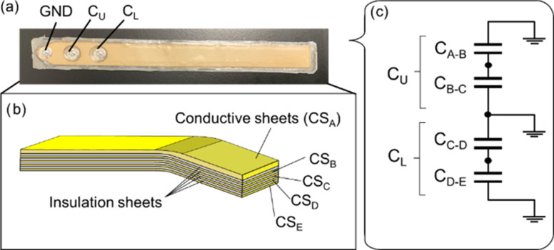
We propose a bending angle sensor (Fig. 1(a)) using five conductive sheets (CSs). As shown in Fig. 1(b), the insulation sheets were sandwiched between the conductive sheets, and then CA-B between CSA and CSB, CB-C between CSB and CSC, CC-D between CSC and CSD, and CD-E between CSD and CSE form the four capacitances. From Fig. 1(c), the combination of CA-B and CB-A is defined as the upper capacitance (CU), because CA-B and CB-A are connected in parallel. In addition, the combination of CC-D and CD-E is defined as a lower capacitance (CL) because CC-D and CD-E are connected in parallel. Moreover, CSA and CSB cover the bending angle sensor based on double-layer capacitance as electromagnetic interference shielding. Electromagnetic interference shielding facilitated the measurement of the human joint angle using a bending angle sensor based on double-layer capacitance to prevent mutual capacitive coupling with the skin.
Fig. 1.
(a) Bending angle sensor based on double-layer capacitance. The ground (GND) was established on the left side of the connections. CU was placed at the middle of the connections, and CL was placed at the right of the connections. (b) Diagram of the bending angle sensor based on double-layer capacitance. Each CSs was overlapped via CSA, CSB, CSC, CSD, and CSE. The insulation sheets were sandwiched between each CSs. (c) Electrical schematic of the bending angle sensor based on double-layer capacitance. CU and CL comprise parallel connections of CSA to CSB and CSC to CSD.
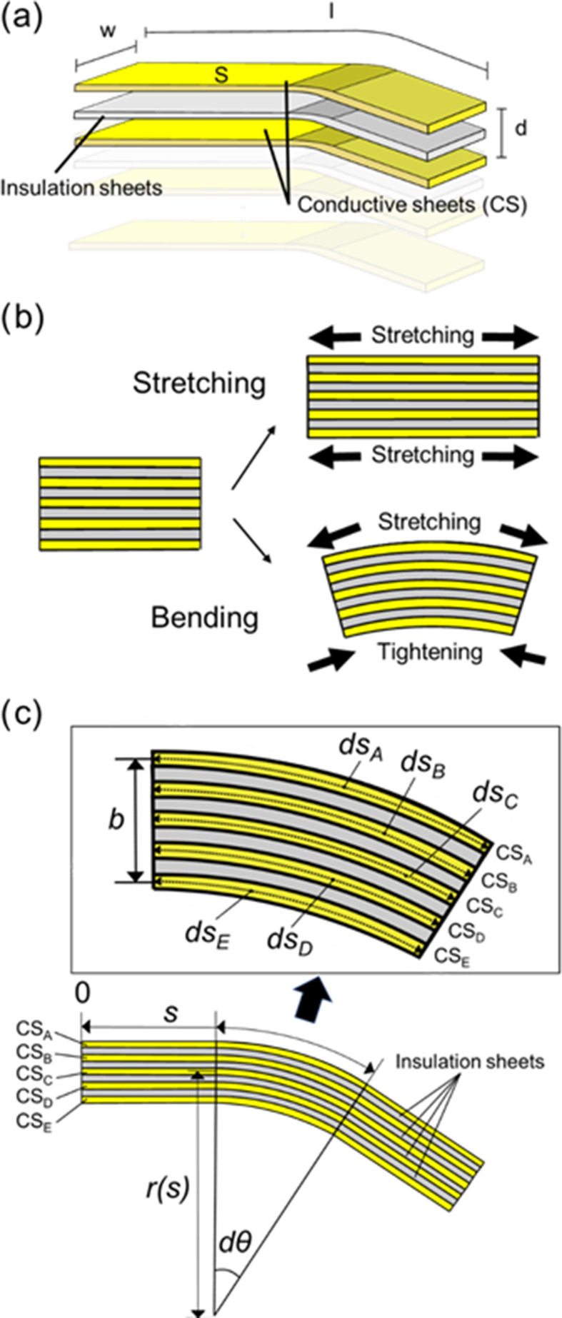
As depicted in Fig. 2(b), the electrode area increases when stretching the bending angle sensor based on the double-layer capacitance. This bending angle sensor based on the double-layer capacitance outputs the capacitance difference between CU and CL. The capacitance values of the two conductive sheets (Fig. 2(a)) as a single-layer capacitive sensor is calculated using the following equation [18]:
 |
where C denotes the capacitance value, ε0 indicates the permittivity in a vacuum, εr refers to the relative permittivity of the insulation sheet, l denotes the length of the bending angle sensor based on double-layer capacitance, and w denotes the width of the bending angle sensor based on double-layer capacitance. Moreover, S = lw yields the area of the overlapped area of the CSs, and d indicates the distance between the CSs. Since (1) is dependent on the overlap area, the overlapped area increases the capacitance when stretched.
Both CU and CL increase, and the capacitance difference between CU and CL remains constant when stretching the bending angle sensor based on the double-layer capacitance. Bending the bending angle sensor based on double-layer capacitance increases the area of CU by stretching the area of CU and decreases the area of CL by tightening the area of CL (Fig. 2(b)). Thus, the bending angle sensor based on double-layer capacitance measures bending but ignores stretching. Moreover, dsA, dsB, dsC, dsD, and dsE represent local curves illustrated in Fig. 2(c). When the bending angle sensor based on double-layer capacitance bends, dsA, dsB, dsD, and dsE can be obtained as shown in the following equation:
 |
where r(s) represents the curvature and the local central angle is dθ. Equation (2) indicates that dsA and dsB stretches are based on dsC, whereas dsD and dsE are tightened based on dsC. The length change rate based on dsC is defined as ɛ. Each ɛ represents (3), substituting (2) for dsA, dsB, dsC, dsD, and dsE yields:
 |
where each length change rate ɛA, ɛB, ɛD, and ɛE is based on dsC. Furthermore, each length change ΔlA, ΔlB, ΔlD, and ΔlE were calculated by integrating ɛA, ɛB, ɛD, and ɛE. Moreover, ΔlA, ΔlB, ΔlD, and ΔlE are expressed as follows:
 |
Fig. 2.
(a) The parameters and capacitances of CSs combined with insulation sheets. (b) Stretch of the bending angle sensor based on double-layer capacitance increases the area of both CU and CL. Bending of the bending angle sensor based on double-layer capacitance increases the area of CU and decreases the area of the CL. (c) The parameter of each four capacitances in the double-layers capacitance under bending.
As mentioned above, the capacitance difference between CU and CL can be obtained from (1) and (4) because ΔlA, ΔlB, ΔlD, and ΔlE are the length changes from l, which is the length of the bending angle sensor based on double-layer capacitance. Consequently, the capacitance difference between CU and CL is given by the following equation:
 |
Equation (5) indicates the capacitance difference between CU and CL, which the bending angle sensor based on double-layer capacitance outputs, including the bending angle. From these equations, we theoretically prove that the capacitance difference between CU and CL is linearly related to the bending angle θ, while the bending angle is independent of the length of the bending angle sensor based on the double-layer capacitance.
B. Fabrication Procedure of the Double-Layer Capacitive Bending Sensor
Regarding the fabrication procedure of the bending angle sensor based on double-layer capacitance, we utilized conductive elastomers (K3B80S, TOYOBO) as the CSs and polyurethane (PU) sheets (MF10F3 3MTS, TOYOBO) as the insulation sheets. CSs were fabricated by mechanically cutting conductive elastomers using a laser engraving machine (Spirit, GCC). The PU sheets with hot-melt material (which melted over 130 °C) on one side were structured to bond the CSs with the insulation sheets. The length of the bending angle sensor based on the double-layer capacitance was 20 cm, and the width of the bending angle sensor based on the double-layer capacitance was 1.8 cm. A fully automatic heat transfer press (HP-84A, HASHIMA) heated 130 °C to melt the hot-melt material and compress the CS and an insulation sheet for 5 s. Once the CS and insulation sheet were compressed, the hot-melted materials were cured after cooling. Finally, five insulation sheets attached to the CSs were compressed for 5 s using a fully automatic heat-transfer press. Three stainless-steel snappers (11.5 mm × 4.5 mm, SEIWA) were contacted and fixed on CSB, CSD, and ground (GND) (CSA, CSC, CSE) to connect a capacitance detection system via lead wires.
C. Capacitive Detection System
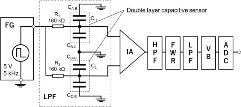
This section describes the custom-designed capacitance detection system. Fig. 3. illustrates the capacitance detection system for the bending angle sensor based on double-layer capacitance. The capacitance detection system comprises a function generator (AFG-21025, RS PRO), a low-pass filter circuit including a bending angle sensor based on double-layer capacitance, an instrumentation amplifier (AD620ANZ, ANALOG DEVICES), a high-pass filter circuit with a cut-off frequency of 100 Hz, a full-wave rectifier circuit using an operational amplifier (TL071ACP, ANALOG DEVICES), a low-pass filter circuit with a cut-off frequency of 5 Hz, a voltage buffer circuit using an operational amplifier, and an analog-to-digital converter (ADC) (AI-1608AY-USB, CONTEC) with 16-bit resolution. The function generator (AFG-21025, RS PRO) contains a low-pass filter circuit that includes a bending-angle sensor based on double-layer capacitance with a rectangular wave voltage (amplitude = 5 V, frequency = 5 kHz). The low-pass filter circuit comprises a known resistance (R1 and R2) and capacitance (CU and CL). The output voltages of the low-pass filter circuit change with the bending angle because the cut-off frequency of the low-pass filter depends on CU and CL. The output voltages of the low-pass filter circuit were amplified, and the output difference was measured using an instrumentation amplifier. In this study, R1 and R2 were selected as 160 kΩ and employed at the acquired maximum output relative to a specific bending angle. The gain of the instrumentation amplifier was set to 40 dB. The output voltage of the capacitance-detection system was acquired using a PC. The sampling frequency of the capacitance detection system was 100 Hz.
Fig. 3.
Electrical equivalent of the bending angle sensor based on double-layer capacitance and a block diagram of the capacitance detection system. Function generator (FG), low-pass filter circuit (LPF), instrumentation amplifier (IA), high-pass filter circuit (HPF), full wave rectifier circuit (FWR), voltage buffer circuit (VB), and analog to digital converter.
D. Evaluation Test of CU and CL Value With the Robotic Arm
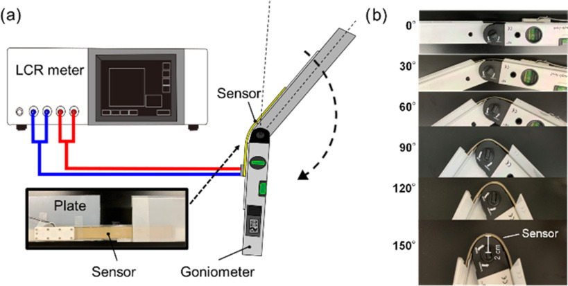
We evaluated the bending angle sensor based on the double-layer capacitance without the capacitive detection system to ensure (5) of the measurement principle. CU and CL were measured with an increase in the bending angle of the sensor using a chemical impedance analyzer (IM3590, Hioki) connected to CU or CL via a four-terminal probe. The chemical impedance analyzer was in the range of 100 mΩ ∼ 100 MΩ, and the impedance and phase angle of the accuracy on the chemical impedance analyzer were within the range ±0.05%, ±0.03°, respectively. In the evaluation test, the amplitude and frequency were set to ±2.5 V and 5 kHz, respectively, in the chemical impedance analyzer. We used a goniometer (with an accuracy of ±0.5°, resolution of 0.1°, and circle radius of 20 mm) when a bending angle sensor based on double-layer capacitance was bent. The bending angle sensor based on double-layer capacitance was arranged on the upper part of the goniometer. Moreover, plastic plates on the goniometer fixed both ends of the bending angle sensor based on the double-layer capacitance to bend for the specified accurate angles (Fig. 4(a)). The goniometer bent in the range of 0°–160° in 5° increments (Fig. 4(b)) corresponding to the knee range of motion (typically in the range of 0°–130°). The 20 samples of CU and CL were measured by the chemical impedance analyzer every 5°. The capacitance difference, represented as CU–CL was calculated by subtracting CU from CL in (5). The correlation coefficients (R2) were calculated by linear regression in least squares on the measured capacitances and bending angles.
Fig. 4.
(a) Test system to ensure CU and CL change with the increase of the bending angle. The bending angle sensor based on double-layer capacitance was bent, referring to the goniometer. CU and CL were measured by the chemical impedance analyzer. (b) Bending angle sensor based on double-layer capacitance with the different bending angles (0°–160°) are shown.
E. Bending and Stretching Test
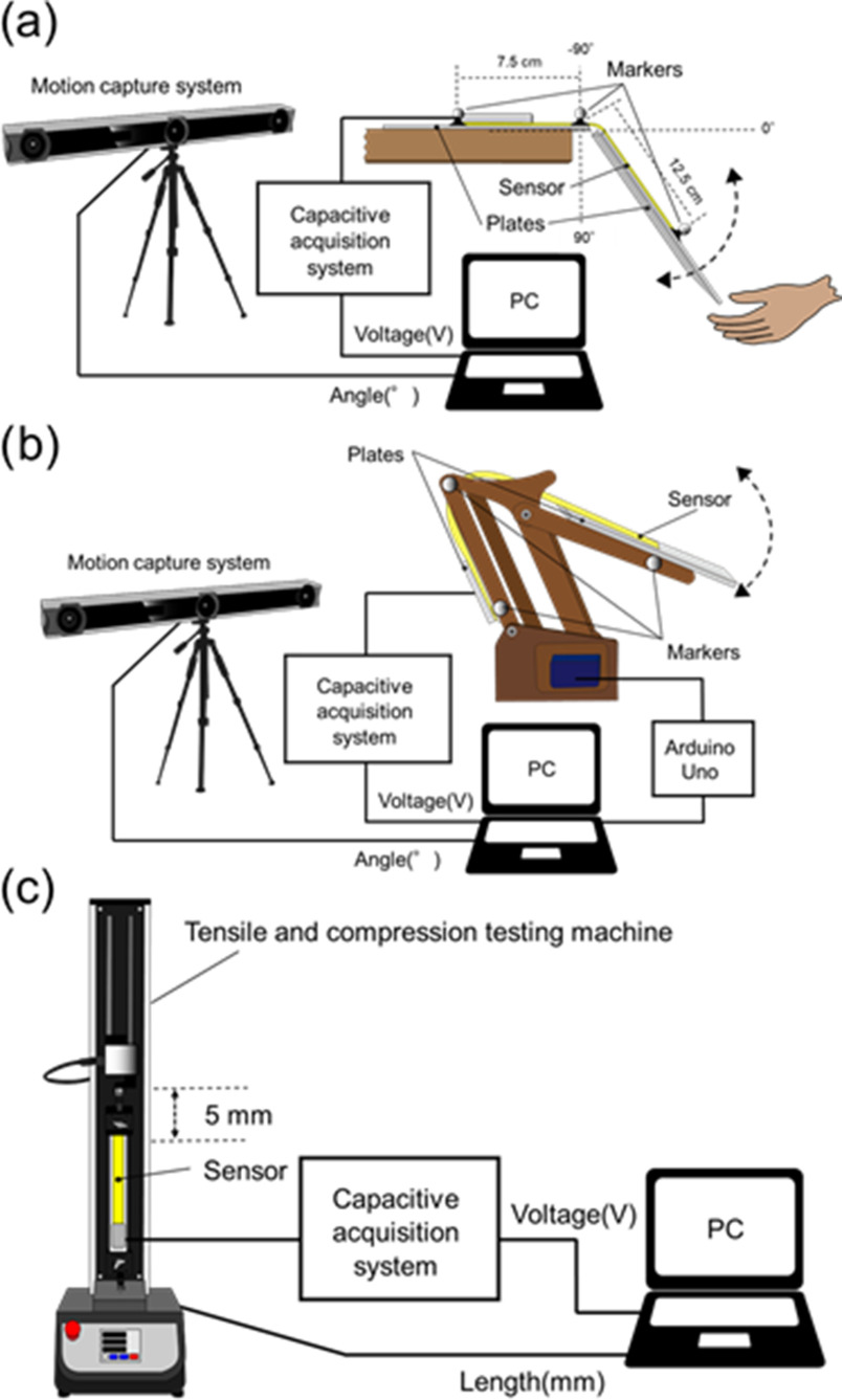
We conducted a bending test for the bending angle sensor based on double-layer capacitance with an optical motion capture system (V120TRIO, OptiTrack) to evaluate the hysteresis and accuracy of the angle measurement. Both ends of the bending angle sensor based on double-layer capacitance were fixed with tape on two plastic plates to prevent the fixed parts of the bending angle sensor based on the double-layer capacitance from bending. In the bending test, the only part that could bend was the angle sensor based on the double-layer capacitance part without the plastic plate. The part without the plastic plate in the bending angle sensor based on the double-layer capacitance was 3 cm. Furthermore, one end of the bending angle sensor based on the double-layer capacitance in connection with the capacitance detection system was fixed to a desk, and the other remained free to pivot around. The optical motion capture acquired the bending angle of the bending angle sensor based on double-layer capacitance as the reference. The optical motion captured the measured markers accurately within 1.00 mm. As illustrated in Fig. 6(a), the three markers were arranged on both ends and the middle of the bending-angle sensor based on double-layer capacitances. Optical motion capture measured the movement of the three markers on the bending angle sensor based on double-layer capacitance. The vectorial angle θ was calculated as the reference angle using the optical motion capture data that acquired the spatial coordinates of the respective marker positions' x, y, and z. The output voltage of the capacitance detection system was acquired using a PC.
Fig. 6.
(a) Test system used for the bending test. (b) Test system used for the robotic arm bending test. The optical motion capture acquired the three markers arranged on the bending angle sensor based on double-layer capacitance, and the capacitance detection system simultaneously measured the output voltage of the bending angle sensor based on double-layer capacitance. (c) Test system used for the stretching test. When the desktop tensile compression tester stretched the bending angle sensor based on double-layer capacitance and the bending angle sensor based on single-layer capacitance, the output voltages of both the bending angle sensor based on double-layer capacitance and the bending angle sensor based on single-layer capacitance were acquired.
The bending angle sensor based on double-layer capacitance was repeatedly bent by hand in the range of 0–130° for 1 min, referencing the knee range of motion. The repetition speed was adjusted to match the rhythm of an electronic metronome beat of 50 rotations per minute (rpm). Moreover, we conducted robotic arm bending tests to confirm the response at different speeds and the reproducibility of the accuracy Fig. 6(b)). We used Arduino Uno (Arduino, Torino) to rotate the robotic arm automatically at three different speeds (16, 32, and 48 rpm), to emulate for the cycling exercise. The robotic arm could rotate in the range of 20°–120°. The robotic arm bending test was repeated 10 times at different speeds.
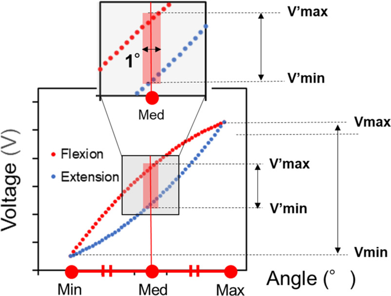
Linear regression in least squares was performed on the output voltage of the bending-angle sensor based on the double-layer capacitance and the reference angle. The estimated angle and R2 were calculated using the linear regression equation of the reference angle to the output voltage of the bending angle sensor based on the double-layer capacitance. The root mean square error (RMSE) was calculated from the error between the estimated and reference angles. Furthermore, Fig. 5 shows the hysteresis evaluation method. The middle angle is the midpoint between the maximum and minimum angles. The maximum and minimum output voltages at the middle angle ±0.5° are represented as  and
and  , respectively [25]. In Fig. 5, the gray region represents as the middle part, and the vertical distance of the red region indicates the differential output voltages of
  and
and  . The maximum and minimum output voltages in the bending angle range in the test are donated as Vmax and Vmin, respectively. Hysteresis is defined as the ratio of the differential output voltage of
  and
and  to the difference between Vmax and Vmin in the bending test. Thus, the hysteresis was evaluated using the following formula:
 |
Fig. 5.
Hysteresis evaluation method. The scatter plot resulted from the measured output voltage with respect to the angle during flexion-extension. The gray region shows the middle part of the scatter plot, including the middle angle. The middle angle is located at the center of the red region. The horizontal distance of the red region is 1°. The vertical distance of the red region is the differential output voltage of  and
and  at the middle angle±0.5°.
Subsequently, we conducted a stretching test for the bending angle sensor based on double-layer capacitance in addition to a bending angle sensor based on single-layer capacitance to ensure that the difference between CU and CL is maintained. The output voltages of stretching were investigated for the bending angle sensor based on the double-layer capacitance and the bending angle sensor based on the single-layer capacitance (Fig. 6(c)). As mentioned in Section II, the bending-angle sensor based on single-layer capacitance responds to both stretching and bending, because the overlap area of the CSs increases. Therefore, a bending angle sensor based on single-layer capacitance was prepared in the stretching test for comparison with the bending angle sensor based on double-layer capacitance. A desktop tensile compression tester (MCT-2150, A&D) stretched the bending angle sensor based on double-layer capacitance and a bending angle sensor based on single-layer capacitance clamped at both ends using metal plates and screws. The desktop tensile compression tester performed five stretching/tightening cycles with a total stretch of 5 mm, at a speed of 10 mm/min. We acquired the output voltages of the bending angle sensor based on the double-layer capacitance and the bending angle sensor based on single-layer capacitance via a capacitance detection system. Moreover, we obtained the length change from a desktop tensile compression tester.
F. Knee Joint Angle Measurement in the Cycling Experiment
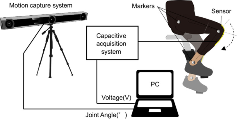
We evaluated the accuracy of the knee bending angle for the bending angle sensor based on double-layer capacitance when a human wearing the wearable garment fixed the bending angle sensor based on double-layer capacitance and performed a high-intensity knee flexion-extension movement, such as cycling exercise, to demonstrate the validity of shielding a two-sided surface on the bending angle sensor based on double-layer capacitance. A healthy subject (age 28 years, weight 56.5 kg, height 162.5 cm) without a history of pain and disability of the hip and knee performed the cycling exercise while wearing the legging with the fixed bending angle sensor based on double-layer capacitance. Prior to the test, informed consent was obtained from all the subjects. The experiment conformed to the standards of the declaration of Helsinki and was approved by the Ethics Committee of Ritsumeikan University (BKC-LSMH-2021-043). In this experiment, the focus was on the cycling exercise, which has a lower risk of falling, smaller knee stresses, and more bending knee joints than gait exercise. The cycling exercise is suitable for the rehabilitation of stroke patients to monitor the knee joint angle and improve locomotor and cardiorespiratory functions [7], [8].
The subject performed cycling at submaximal intensities for 10 min, adjusting the knee flexion-extension speed at 30 rpm using an electronic metronome. The double-layer capacitive bending was attached to a legging (MCM8858, UNDER ARMOUR) by sewing with a needle and thread. The subject wore the leggings and adjusted their position on the knee joint, as illustrated in Fig. 7. The output voltage of the bending angle sensor based on double-layer capacitance was recorded for 10 min by a PC using a capacitance detection system fixed on a desk. The optical motion capture recorded the knee flexion-extension angle as the reference angle ten times for 30 s every minute from the beginning of the cycling exercise. The three markers were anchored to the greater trochanter, lateral epicondyle of the femur, and lateral malleolus of the ankle on the right side of the subject. We calculated the vector angle θ as the reference angle from the three markers that formed the straight lines. Subsequently, the acquired output voltage of the bending angle sensor based on the double-layer capacitance was separated into ten output voltages. Linear regression in least squares was performed on each separated output voltage of the bending angle sensor based on double-layer capacitance and ten reference angles for 30 s, and each of the estimated angles, R2, and RMSE were calculated. Furthermore, the slopes of the baselines of the estimated angles were calculated using linear least-squares regression and the angles for all 10 min datasets and 10 separate 30 s datasets obtained using the bending angle sensor based on double-layer capacitance were estimated. The slopes of the baselines of the reference angles were also calculated using linear least-squares regression, and the results were compared with the calculated slopes of the estimated angles.
Fig. 7.
Test system of the knee angle measurement during the cycling exercise.
III. Results
A. Evaluation Test of Cu and Cl Value With the Robotic Arm
Fig. 8 illustrates the capacitances (a: CU, b: CL, and c: CU-CL) measured by the chemical impedance analyzer to the bending angle referencing the goniometer. The capacitive change of CU increased linearly with the bending angle (R2 = 0.998), whereas the capacitive change in CL decreased linearly with the bending angle (R2 = 0.993), as described in Section II. Furthermore, the capacitive change in the CU-CL was more linearly proportional to the bending angle (R2 = 0.999), as depicted in Fig. 8(c).
Fig. 8.

Correlation plots between the capacitances ((a) CU, (b) CL, and (c) CU–CL) measured by the chemical impedance analyzer and the bending angle measured by the goniometer. CU–CL was calculated by subtracting CU from CL.
B. Bending and Stretching Test
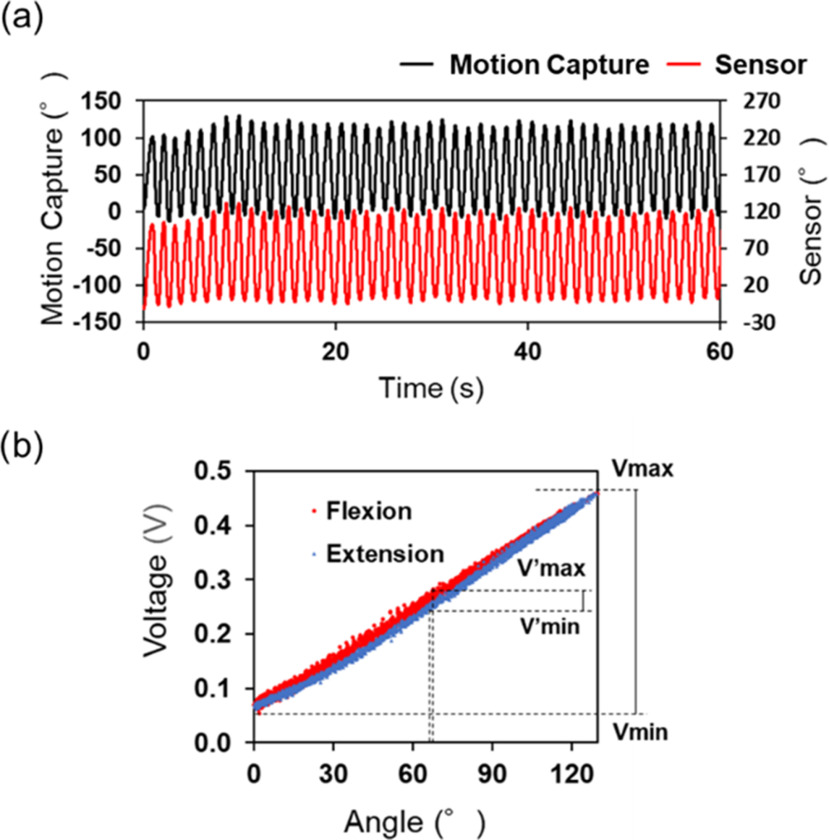
Fig. 9(a) presents the dynamic response comparison between optical motion capture and the bending angle sensor based on double-layer capacitance. We observed that these dynamic responses were similar in the bending test. The hysteresis and RMSE of the bending angle sensor based on double-layer capacitance was 8.0% and 3.1° within 0° ∼ 130°, based on the reference angle. Fig. 9(b) illustrates the hysteresis curve of the bending angle sensor based on double-layer capacitance based on the reference data. There is great agreement between the output behavior of the flexion (red plots) and the extension (blue plots). Moreover, R2 of the output voltage and the reference data was 0.996, indicating the high linearity.
Fig. 9.
(a) Dynamic response comparison between the bending angle sensor based on double-layer capacitance and optical motion capture for 1 min. The black line represents the knee angle of the optical motion capture, and the red line represents the estimated knee angle of the bending angle sensor based on double-layer capacitance. (b) Hysteresis curve of the bending angle sensor based on double-layer capacitance (hysteresis = 8.0%). The red plots represent flexion, and the blue plot represents extension. The maximum output voltage is within 0°∼130° (Vmax), minimum output voltage is within 0°∼130° (Vmin), maximum output voltage is within ±65°  , the minimum output voltage within ±65°
  ).
).
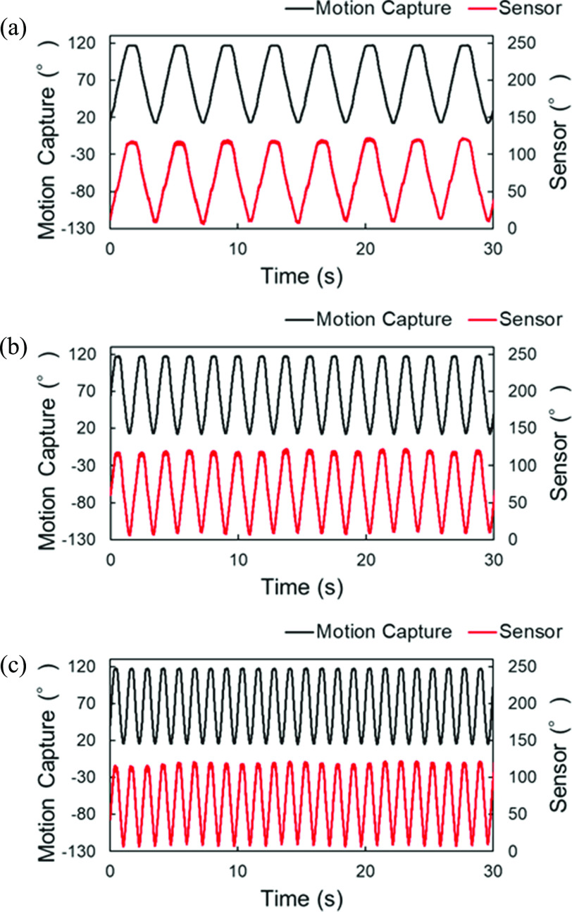
Fig. 10 compares the results for each representative dynamic response obtained over 30 s in the robotic arm bending tests. The output voltages from the bending angle sensor based on the double-layer capacitance could respond to the movement of the robotic arm. The results for the hysteresis (based on all the trials), RMSE, and R2 at 16 rpm were 7.5 ± 1.0%, 2.9 ± 0.2°, and 0.994 ± 0.001, respectively. Similarly, the hysteresis, RMSE, and R2 based on all the trials at 32 rpm were 7.7 ± 0.7 %, 3.0 ± 0.1°, and 0.994 ± 0.001, respectively. The RMSE and R2 values based on all trials were 3.5 ± 0.2 and 0.991 ± 0.001 at 48 Hz, respectively. The hysteresis at 48 rpm was 10.0 ± 1.2 %.
Fig. 10.
Dynamic response comparisons between the bending angle sensor based on double-layer capacitance and optical motion capture for 30 s at (a) 16 rpm, (b) 32 rpm, and (c) 48 rpm.
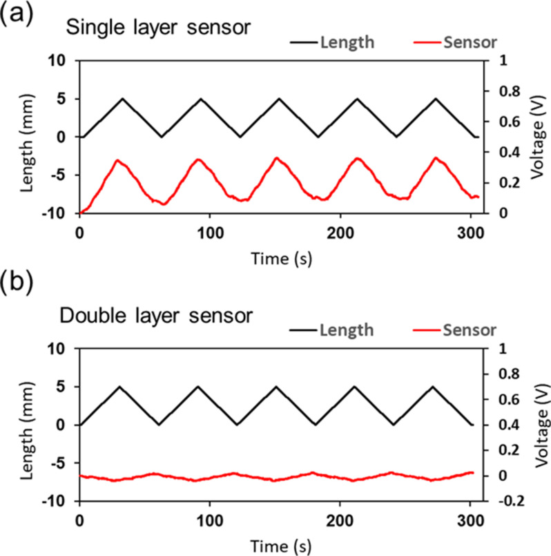
Fig. 11 shows the dynamic response of the single-layer capacitive sensor (Fig. 11(a)) and the bending angle sensor based on double-layer capacitance (Fig. 11(b)) obtained using the desktop tensile compression tester. The estimated angle of the bending angle sensor based on single-layer capacitance was affected from −0.4° to 54.4°, whereas the estimated angle of the bending angle sensor based on double-layer capacitance was affected from −9.2° to 9.8°. The bending angle sensor based on double-layer capacitance reduced the estimated angle error under stretching by 65%. The results of the stretching test indicate that the bending-angle sensor based on the double-layer capacitance minimized the output voltage change under stretching.
Fig. 11.
(a) Dynamic response comparison between the output voltage and the length change in the stretching test with a total stretch of 5 mm at a speed of 10 mm/min. Bending angle sensor based on (a) single-layer capacitance, and (b) double-layer capacitance.
C. Knee Joint Angle Measurement in the Cycling Experiment
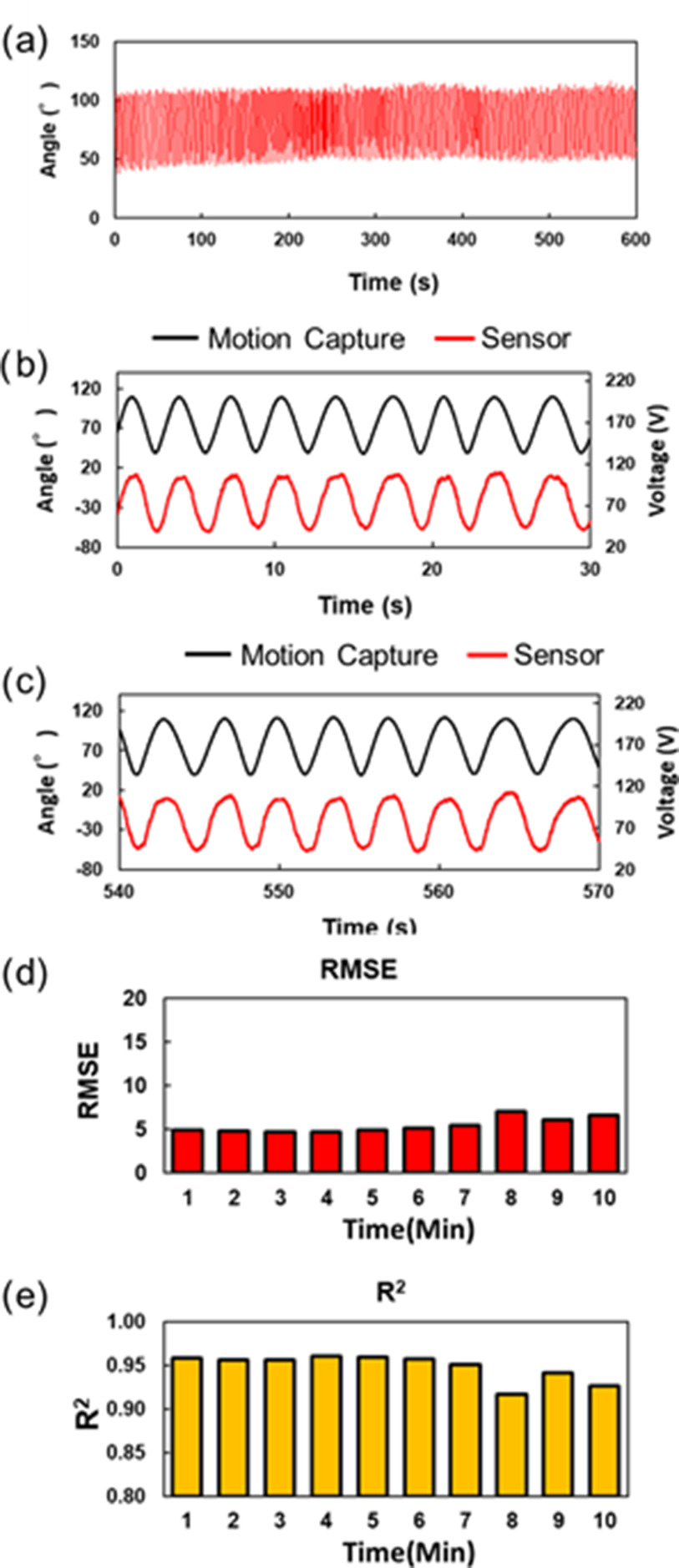
Fig. 12(a) illustrates the estimated angle of the bending angle sensor fixed on the leggings, which is based on double-layer capacitance. Although the knee flexion-extension motion may cause spike noises owing to excessive tensions around the connectors, noise spikes and large amplitude changes were not observed, even during the cycling exercise. Fig. 12(b) and (c) present the output voltage of the bending angle sensor based on double-layer capacitance and the reference angle for 30 s after the start and before the finish. Great repeatability and similarity were observed for both results.
Fig. 12.
(a) Result of the estimated knee angle measurement during the cycling exercise at 30 rpm for 10 min. The dynamic response comparison between the bending angle sensor based on double-layer capacitance and the optical motion capture for (b) 30 s after the start and (c) 30 s before the finish. The black line represents the knee angle of the optical motion capture, and the red line represents the output voltage of the bending angle sensor based on double-layer capacitance. (d) Trends in time of RMSEs. (e) Trends in time of R2.
Figs. 10(e) and 12(d) show fluctuations of RMSE and R2 during cycling exercise for 10 min. The RMSE ranged from 4.7° to 7.0°, and R2 ranged from 0.917 to 0.960, maintaining high linearity when a human wore the leggings. RMSE and R2 highlighted the high accuracy of the bending angle sensor based on double-layer capacitance.
Another concern is the slow drift, which modifies the capacitance difference between CU and CL. However, there was negligible drift (slope < 0.01°) for all 10 min data throughout the cycling exercise. Table I shows the calculated slopes of the baselines for the estimated angles and the reference angles for 10 separate 30 s datasets. The maximum slope of the estimated angle was 0.30° at 9 min, and the slope of the reference angle was 0.26° at 9 min. The minimum slopes of the estimated and reference angles were 0.21° and 0.26° at 8 min, respectively.
TABLE I. Slopes Calculated for 10 Separate 30 s Datasets During the Cycling Exercise.
| Time (Min) | Bending Angle Sensor (°) | Motion Capture (°) |
|---|---|---|
| 1 | -0.07 | -0.18 |
| 2 | 0.05 | -0.04 |
| 3 | 0.09 | 0.06 |
| 4 | 0.08 | 0.10 |
| 5 | -0.14 | -0.13 |
| 6 | -0.02 | 0.03 |
| 7 | -0.02 | 0.01 |
| 8 | -0.21 | -0.20 |
| 9 | 0.30 | 0.26 |
| 10 | <0.01 | -0.02 |
| Average | <0.01 | -0.01 |
| SD | 0.13 | 0.13 |
IV. Discussion
A bending angle sensor based on double-layer capacitance was developed to solve the problems of hysteresis and simultaneous detection of stretching and bending. We conducted tests on the bending angle sensor. Subsequently, we demonstrated that knee joint angle monitoring using a bending angle sensor based on double-layer capacitance is useful in cycling exercises.
Fig. 8 shows that the bending angle sensor based on double-layer capacitance increases the area of CU and decreases the area of CL when bending, so that the capacitance difference between CU and CL is significantly related to the bending angle based on (5). This means that the capacitance difference between CU and CL is proportional to the angle. In similar studies, Totaro et al [24] and Nakamoto et al [26] confirmed the linearity of capacitance sensors in tensile tests instead of bending tests. In other words, it is elongation, not bending, that is being measured, and it is unclear whether the relationship with angle is linear. Also, Li et al. reported a quadratic relationship between the capacitance of capacitive bend angle sensors and the bend angle at calibration [27]. The fact that the relationship between angle and sensor output is expressed as quadratic means that it is difficult for this sensor to detect any angle as a uniform sensitivity. For the sensor we developed, the relationship can be expressed as linear (CU: R2 = 0.998; CL: R2 = 0.993), because it is capable of detecting with uniform sensitivity for any angle [12]. In conclusion, we confirm that bending angle sensors based on double-layer capacitance can measure bending angles more accurately than other single-layer capacitance sensors by calculating the difference between CU and CL.
The hysteresis and RMSE are compared with the optical motion capture in Fig. 9 were 8.0 %, 3.1 in the bending test, respectively. In addition, the robotic arm bending test demonstrated that the bending angle sensor based on double-layer capacitance could respond at different speeds (Fig. 10) and had a reproducible accuracy. Tognetti et al. reported that a bending angle sensor based on double-layer resistance exhibited different behaviors between flexion and extension [13]. Comparison of the scatter diagrams in Fig. 9(b) and [13] clearly showed that the hysteresis of the bending angle sensor based on double-layer capacitance was reduced compared to that of the bending angle sensor based on double-layer resistance. The capacitance of capacitive sensors depends on the overlap area. Accordingly, capacitive sensors can reduce hysteresis, regarded as a problem with resistive sensors [18], [19]. The bending angle sensor based on double-layer capacitance overcame the mutual capacitive couplings, considered an important obstacle in capacitive sensors [22], [23], by shielding using a two-sided surface [24]. These improvements resulted in the high accuracy and small hysteresis of the bending angle sensor based on the double-layer capacitance in the bending test.
Fig. 11 illustrated that the bending angle sensor could minimize the change in the capacitive difference in the stretching test. According to (5), the capacitance difference between CU and CL remains constant when the bending angle sensor is based on double-layer capacitance stretching. Thus, theoretically, the output voltage of the bending angle sensor based on the double-layer capacitance does not change [13]. However, the output voltage of the bending angle sensor based on the double-layer capacitance changed from −9.2° to 9.8° and exhibited an anti-phase relationship with the length change in the stretching test. We assume that this factor of the output voltage change is a tiny area difference between the CU and CL in the fabrication of the bending angle sensor based on double-layer capacitance [18]. It is possible that the change in output voltage occurred as the overlapped area of the CL became larger than that of the CU under slight stretching.
As illustrated in Fig. 12, the RMSEs ranged from 4.7° to 7.0° in the cycling experiments for the human joint. The RMSE and R2 in the cycling experiment were slightly lower in accuracy than those in the bending test because the attachment positions of the bending angle sensor based on double-layer capacitance on the patella differed from the anchored marker positions [17], [26], [28]. The output voltages of the bending angle sensor based on double-layer capacitance delayed the cycles. The RMSE and R2 slightly decreased at 8 min, indicating an improvement for a suitable attachment to the wearable garments. Future work will include seeking suitable attachments for complex motion measurements. For example, thin non-slippery pads can tighten the sensor attachments to prevent the slippage of sensors attached on the skin [17]. Alternatively, compensation algorithms including detailed models of bone and muscle shapes could be used to overcome this issue [26].
The slope of all 10-min data proves that the slow drift of the capacitance difference between CU and CL could be ignored, but some slopes of the separate 30 s datasets were large (Table I). However, some large slopes of the reference angle were observed, simultaneously with large slopes on the estimated angle. When the slope of the estimated angle was small (within ±0.05), the slopes of the reference angle fit within ±0.05. The results indicated that the knee joint angle affected some large slopes on the estimated angle. Therefore, the bending angle sensor based on double-layer capacitance demonstrated high accuracy in measuring the knee joint angle [29].
The results of the cycling exercises are shown in Fig. 12, shielding a two-sided surface on a bending angle sensor based on double-layer capacitance demonstrated the prevention of mutual capacitive couplings with the skin. The addition of CSA and CSE as GND prevents electromagnetic interference [24] and stable capacitance measurement because of the increase in the capacitance of CU and CL by the parallel connection. The cycling experiment confirmed the necessity of shielding when measuring human motion using a double-layout capacitive bending sensor.
Table II compares the type of stretchable and electrically conductive sensors to emphasize the benefits of the bending angle sensor based on double-layer capacitance. Although Mengüç et al. [17] and Tognetti et al. [13] reported that resistance sensors exhibited hysteresis, The bending angle sensor based on double-layer capacitance minimized the hysteresis in the bending test. Furthermore, the capacitance difference of the double-layer capacitive sensor could be maintained during stretching, compared to the operating principle of other sensors [17], [24], [27]. The experiments in this study highlight that we performed a broader bending angle range in the bending test and cycling experiment, comparing other studies in static and dynamic experiments. Evidently, the knee joint angle is more extensive in the cycling leg test than during walking [17], [24], [27], [30] and running [17], [24]. Additionally, our cycling experiment continuously recorded knee joint angles for longer than other studies [17], [24], [27] and evaluated the drifts for separate 30 s datasets and all 10 min of data, and demonstrated that the drift was negligible. It should be emphasized that the bending angle sensor based on double-layer capacitance exhibited high accuracy, despite the broader bending angle range and recording longer time.
TABLE II. Comparison Between Different Types of Stretchable and Electrically Conductive Sensors.
| Reference | Type of sensor | Hysteresis | Detection of only bending | Sensor position | Evaluation metrics(Static test) | Evaluation metrics (Dynamic test) |
|---|---|---|---|---|---|---|
| Mengüç et al. [17] | Resistive | Hip, knee, and ankle | Electrical hysteresis percentages (and linearity ratios) of 7.8% (0.77 linearity), 3.9% (0.91), and 4.3% (0.92) for the hip, knee, and ankle (mechanical loading and unloading) | RMSE < 5° (Walking at 0.89 m/s for 60 s) RMSE < 15° (Running at 2.7 m/s for 60 s) |
||
| Oubre et al. [30] | Resistive (potentiometer) |
Knee | RMSE = 5.0 ± 1.0° MAE = 3.9 ±0.8° (Walking at three different self-selected speeds) |
|||
| Wood et al. [28] | Resistive | Knee | The average RMSE = 7.6° (Knee flexion-extension movements and walking) | |||
| Tognetti et al. [13] | Resistive (Double-layer) | ✓ | Knee | Maximum standard deviation = 5100 Ω, corresponding to an angular error of 5.3° (quasi-static flexion test in the 0–90° range) | Maximum error = 5.0° (Knee flexion-extension movements) | |
| Nakamoto et al. [26] | Capacitive | ✓ | Knee and ankle |
R2 = 0.9993 (stretching test in the 30–70 mm range) | Mean error = 4.4 ± 3.6° (knee flexion-extension movements) |
|
| Li et al. [27] | Capacitive | ✓ | Ankle | R2 = 0.9991 (bending test in the 0–90° range) | RMSE < 3.0° (Horizontal and descending walking for 90 s) RMSE < 5.0° (Ascending walking for 90 s) |
|
| Totaro et al. [24] | Capacitive (Shielding) | ✓ | Knee and ankle | Linear behavior in the entire range (tensile test) | RMSE < 4.0° (Ten knee flexion/extension in the 0–90° range) | |
| This work | Capacitive (Double-layer and shielding) | ✓ | ✓ | Knee | RMSE = 3.1° (bending test in the 0–130° range) RMSE = 2.9 ± 0.2° (robotic arm bending test in the 20–120° range at 16 rpm) RMSE = 3.0 ± 0.1° (robotic arm bending test in the 20–120° range at 32 rpm) RMSE = 3.5 ± 0.2° (robotic arm bending test in the 20–120° range at 48 rpm) |
RMSE < 7.0° (Cycling experiment for 10 min) |
It is well known that temperature and humidity affect the dielectric constant. Our proposed sensor, due to its structure, is expected to be less affected by temperature and humidity. Because, assuming that the influence values due to temperature and humidity superimposed on CU and CL are comparable, the influence values of temperature and humidity are expected to cancel out because the difference between CU and CL is calculated. However, this was not proved in this experiment. This needs to be verified in future studies.
The CSs in the bending angle sensor based on double-layer capacitance do not hinder movement because of the stretchable materials. Furthermore, the feature of the bending angle sensor based on double-layer capacitance can be easily attached to a wearable garment. Therefore, the bending angle sensor based on double-layer capacitance can be used easily in rehabilitation and comfortably monitors the joint angle of stroke patients. Rehabilitation monitoring using a bending angle sensor based on double-layer capacitance is expected to provide quantitative and objective joint function evaluations and contribute to determining the prognosis and efficacy of an intervention in the post-operative rehabilitation period.
V. Conclusion
Joint angle monitoring is variable, particularly during the postoperative rehabilitation period. Although cameras, including marker-based optical motion capture systems, can measure with high accuracy, some limitations of use include space restrictions for the distance and the requirement to set the devices in various locations. Stretchable and electrically conductive sensors embedded in wearable garments can be used to overcome these limitations. However, conventional stretchable and electrically conductive sensors face some difficulties with hysteresis and the simultaneous detection of stretching and bending. Therefore, we developed a bending angle sensor based on double-layer capacitance that can maintain the output constant by stretching and acquiring the change in the electrical capacitance difference between CU and CL by bending. In this study, a bending angle sensor based on double-layer capacitance was fixed on the leggings, and the knee joint angle was measured during the cycling exercise. In the stretching and bending tests, we ensured a constant difference under stretching and a hysteresis behavior under bending. We demonstrated that the bending-angle sensor based on double-layer capacitance can effectively minimize the change in capacitance difference in the stretching test. Moreover, the hysteresis and RMSE based on optical motion capture were small in the bending test. Furthermore, the result of the cycling experiment exhibited a low RMSE even when the human wears the leggings fixed with the bending-angle sensor based on double-layer capacitance. The results show that shielding a two-sided surface on the bending angle sensor based on double-layer capacitance enabled joint angle monitoring during the cycling exercise. Consequently, the new bending-angle sensor based on double-layer capacitance provides practical applications of quantitative and observational evaluation tools for knee joint functions. In future work, we will seek suitable attachments to the bending-angle sensor to perform complex motion measurements.
Funding Statement
This work was supported by JST COI under Grant JPMJCE1306.
Contributor Information
Daisuke Goto, Email: sh0100hp@ed.ritsumei.ac.jp.
Yusuke Sakaue, Email: sakaue@fc.ritsumei.ac.jp.
Tatsuya Kobayashi, Email: gr0520kf@ed.ritsumei.ac.jp.
Kohei Kawamura, Email: sh0196vh@ed.ritsumei.ac.jp.
Shima Okada, Email: s-okada@fc.ritsumei.ac.jp.
Naruhiro Shiozawa, Email: shiozawa@fc.ritsumei.ac.jp.
References
- [1].Hasebe Y. et al., “Factors affecting early knee-flexion range of motion after total knee arthroplasty,” J. Phys. Ther. Sci., vol. 33, no. 9, pp. 672–675, 2021, doi: 10.1589/jpts.33.672. [DOI] [PMC free article] [PubMed] [Google Scholar]
- [2].Krafft F. C. et al. , “How does functionality proceed in ACL reconstructed subjects? Proceeding of functional performance from pre- to six months post-ACL reconstruction,” PLoS One, vol. 12, no. 5, 2017, Art. no. e0178430, doi: 10.1371/journal.pone.0178430. [DOI] [PMC free article] [PubMed] [Google Scholar]
- [3].Kocak U. Z. et al. , “Assessing the knee flexion range of motion after total knee arthroplasty: Technology versus senses,” J. Bodywork Movement Therapies, vol. 28, pp. 547–551, 2021, doi: 10.1016/j.jbmt.2021.09.011. [DOI] [PubMed] [Google Scholar]
- [4].Chino N. et al. , “Stroke impairment assessment set(SIAS). A new evaluation instrument for stroke patients,” Jpn. J. Rehabil. Med., vol. 31, no. 2, pp. 119–125, 1994, doi: 10.2490/jjrm1963.31.119. [DOI] [Google Scholar]
- [5].Fugl-Meyer A. R. et al. , “The post-stroke hemiplegic patient A method for evaluation of physical performance,” Scand. J. Rehabil. Med., vol. 7, no. 1, pp. 13–31, 1975. [PubMed] [Google Scholar]
- [6].Zhou H. et al. , “Inertial measurements of upper limb motion,” Med. Biol. Eng. Comput., vol. 44, no. 6, pp. 479–487, 2006, doi: 10.1007/s11517-006-0063-z. [DOI] [PubMed] [Google Scholar]
- [7].El-Tamawy M. S. et al. , “Effect of cycling exercise on motor excitability and gait abnormalities in stroke patients,” Egyptian J. Neurol. Psychiatry Neurosurgery, vol. 57, no. 1, pp. 1–7, 2021, doi: 10.1186/s41983-020-00236-6. [DOI] [Google Scholar]
- [8].Ofori E. K. et al. , “Ergometer cycling improves the ambulatory function and cardiovascular fitness of stroke patients-A randomized controlled trial,” J. Phys. Ther. Sci., vol. 31, no. 3, pp. 211–216, 2019, doi: 10.1589/jpts.28.211. [DOI] [PMC free article] [PubMed] [Google Scholar]
- [9].Kontson K. L. et al. , “Assessing kinematic variability during performance of Jebsen-Taylor hand function test,” J. Hand Ther., vol. 33, no. 1, pp. 34–44, 2020, doi: 10.1016/j.jht.2018.10.002. [DOI] [PubMed] [Google Scholar]
- [10].Shyr T. W. et al. , “A textile-based wearable sensing device designed for monitoring the flexion angle of elbow and knee movements,” Sensors, vol. 14, no. 3, pp. 4050–4059, 2014, doi: 10.3390/s140304050. [DOI] [PMC free article] [PubMed] [Google Scholar]
- [11].Alarcón-Aldana A. C. et al. , “Upper limb physical rehabilitation using serious videogames and motion capture systems: A systematic review,” Sensors, vol. 20, no. 21, pp. 1–22, 2020, doi: 10.3390/s20215989. [DOI] [PMC free article] [PubMed] [Google Scholar]
- [12].Lorussi F., Galatolo S., and De Rossi D. E., “Textile-based electrogoniometers for wearable posture and gesture capture systems,” IEEE Sensors J., vol. 9, no. 9, pp. 1014–1024, Sep. 2009, doi: 10.1109/JSEN.2009.2024867. [DOI] [Google Scholar]
- [13].Tognetti A. et al. , “New generation of wearable goniometers for motion capture systems,” J. Neuroen. Rehabil., vol. 11, no. 1, 2014, Art. no. 56, doi: 10.1186/1743-0003-11-56. [DOI] [PMC free article] [PubMed] [Google Scholar]
- [14].Amjadi M. et al. , “Stretchable, skin-mountable, and wearable strain sensors and their potential applications: A review,” Adv. Funct. Mater., vol. 26, no. 11, pp. 1678–1698, 2016, doi: 10.1002/adfm.201504755. [DOI] [Google Scholar]
- [15].Kang D. et al. , “Ultrasensitive mechanical crack-based sensor inspired by the spider sensory system,” Nature, vol. 516, no. 7530, pp. 222–226, 2014, doi: 10.1038/nature14002. [DOI] [PubMed] [Google Scholar]
- [16].Boland C. S. et al. , “Sensitive, high-strain, high-rate bodily motion sensors based on graphene-rubber composites,” Amer. Chem. Soc. Nano, vol. 8, no. 9, pp. 8819–8830, 2014, doi: 10.1021/nn503454h. [DOI] [PubMed] [Google Scholar]
- [17].Mengüç Y. et al. , “Wearable soft sensing suit for human gait measurement,” Int. J. Robot. Res., vol. 33, no. 14, pp. 1748–1764, 2014, doi: 10.1177/0278364914543793. [DOI] [Google Scholar]
- [18].Nakamoto H., Ootaka H., Tada M., Hirata I., Kobayashi F., and Kojima F., “Stretchable strain sensor based on areal change of carbon nanotube electrode,” IEEE Sensors J., vol. 15, no. 4, pp. 2212–2218, Apr. 2015, doi: 10.1109/JSEN.2014.2377022. [DOI] [Google Scholar]
- [19].Lipomi D. J. et al. , “Skin-like pressure and strain sensors based on transparent elastic films of carbon nanotubes,” Nature Nanotechnol., vol. 6, no. 12, pp. 788–792, 2011, doi: 10.1038/nnano.2011.184. [DOI] [PubMed] [Google Scholar]
- [20].Shin U. H. et al. , “Highly stretchable conductors and piezocapacitive strain gauges based on simple contact-transfer patterning of carbon nanotube forests,” Carbon, vol. 80, no. 1, pp. 396–404, 2014, doi: 10.1016/j.carbon.2014.08.079. [DOI] [Google Scholar]
- [21].Cai L. et al. , “Super-stretchable, transparent carbon nanotube-based capacitive strain sensors for human motion detection,” Sci. Rep., vol. 3, 2013, Art. no. 3048, doi: 10.1038/srep03048. [DOI] [PMC free article] [PubMed] [Google Scholar]
- [22].Yao S. and Zhu Y., “Wearable multifunctional sensors using printed stretchable conductors made of silver nanowires,” Nanoscale, vol. 6, no. 4, pp. 2345–2352, 2014, doi: 10.1039/c3nr05496a. [DOI] [PubMed] [Google Scholar]
- [23].Qiu Y. et al. , “A self-conformable smart skin with sensing and variable stiffness functions,” Adv. Intell. Syst., vol. 1, no. 5, 2019, Art. no. 1900054, doi: 10.1002/aisy.201900054. [DOI] [Google Scholar]
- [24].Totaro M. et al. , “Soft smart garments for lower limb joint position analysis,” Sensors, vol. 17, no. 10, 2017, Art. no. 2314, doi: 10.3390/s17102314. [DOI] [PMC free article] [PubMed] [Google Scholar]
- [25].Gu J. et al. , “Wearable strain sensors using light transmittance change of carbon nanotube-embedded elastomers with microcracks,” Amer. Chem. Soc. Appl. Mater. Interfaces, vol. 12, no. 9, pp. 10908–10917, 2020, doi: 10.1021/acsami.9b18069. [DOI] [PubMed] [Google Scholar]
- [26].Nakamoto H. et al. , “Joint angle measurement by stretchable strain sensor,” J. Ambient Intell. Humaniz Comput., vol. 9, no. 3, pp. 1–6, 2018, doi: 10.1007/s12652-018-0915-z. [DOI] [Google Scholar]
- [27].Li X. et al. , “Flexible capacitive curvature sensor with one-time calibration for amphibious gait monitoring,” Soft Robot., vol. 8, no. 2, pp. 164–174, 2021, doi: 10.1089/soro.2019.0151. [DOI] [PubMed] [Google Scholar]
- [28].Wood D. S. et al. , “Accurate prediction of knee angles during open-chain rehabilitation exercises using a wearable array of nanocomposite stretch sensors,” Sensors, vol. 22, no. 7, 2022, Art. no. 2499, doi: 10.3390/s22072499. [DOI] [PMC free article] [PubMed] [Google Scholar]
- [29].Al Borno M. et al. , “OpenSense: An open-source toolbox for inertial-measurement-unit-based measurement of lower extremity kinematics over long durations,” J. Neuroeng. Rehabil., vol. 19, no. 1, pp. 1–11, 2022, doi: 10.1186/s12984-022-01001-x. [DOI] [PMC free article] [PubMed] [Google Scholar]
- [30].Oubre B. et al. , “A simple low-cost wearable sensor for long-term ambulator,” IEEE Trans. Biomed. Eng., vol. 67, no. 12, pp. 3483–3490, Dec. 2020, doi: 10.1109/TBME.2020.2988438. [DOI] [PMC free article] [PubMed] [Google Scholar]


