Abstract
Inconel 718 is a Ni superalloy with superior mechanical properties, even at high temperatures. However, due to its high hardness and low thermal conductivity, it is considered a difficult-to-machine material. This material is widely used in applications that require good dimensional stability, making the milling process the most used in machining this alloy. The wear resulting from this process and the quality of the machined surface are still challenging factors when it comes to Inconel 718. TiAlN-based coating has been used on cutting tools with Yttrium as a doping element to improve the process performance. Based on this, this work evaluated the machined surface integrity and wear resistance of cutting tools coated using Physical Vapor Deposition (PVD) HiPIMS with TiAlYN in the end milling of Inconel 718, varying the process parameters such as cutting speed (vc), feed per tooth (fz), and cutting length (Lcut). It was verified that the Lcut is the parameter that exerts the most significant influence since, even at small distances, Inconel 718 already generates high tool wear (TW). Furthermore, the main wear mechanisms were abrasive and adhesive wear, with the development of a built-up edge (BUE) under a125 m/min feed rate (f) and a Lcut = 15 m. Chipping, cracking, and delamination of the coating were also observed, indicating a lack of adhesion between the coating and the substrate, suggesting the need for a good interlayer or the adjustment of the PVD parameters.
Keywords: milling, Inconel 718, TiAlYN coatings, HiPIMS technique, tool wear mechanisms, surface integrity
1. Introduction
The class of materials known as Inconel are Ni-Cr-based superalloys, recognised for having superior mechanical properties and good fatigue and creep behaviour up to 700 °C [1]. In their composition, generally, some elements, such as Al, Ti, Nb, Co, Cu, W, and Fe, are added, with the aim to improve their mechanical properties and corrosion resistance [2]. Within this class, Inconel 718 stands out. This material is a precipitation-hardened superalloy, with elements such as Ni and Cr contributing to its corrosion resistance [3,4]. Furthermore, Inconel 718 combines its resistance to corrosion [4] with excellent mechanical properties at high temperatures and good weldability [5], and is widely used in aircraft, gas turbines, turbocharger rotors, nuclear reactors, liquid fuel rockets, critical rotating parts, airfoils, etc. [6,7,8,9]. It can represent 30% of the total weight of an aircraft engine [10,11].
However, due to its properties, such as high hardness and low thermal conductivity, conventional machining and forming processes are challenging, making this alloy a difficult-to-machine material [12,13,14]. During machining, the work hardening of this alloy and its reactivity with the cutting tool material at high temperatures plastically deform the cutting tool, resulting in an inferior surface quality of the machined part [15]. This fact, added to the tendency of this alloy to adhere to the surface of cutting tools, makes machining even more difficult [16]. However, machining is still widely used in industries to produce high-precision and quality parts [17]. Of the machining processes, milling, a more flexible process with great dimensional accuracy, is the most used in the machining of Inconel 718.
Many authors have based their research on milling Inconel 718 [18,19,20,21,22,23], emphasising the fact that it is a challenging material when it comes to conventional machining processes. For example, Liao et al. [24] analysed the end milling of Inconel 718 under various cutting speeds (vc) with carbide tools. It was found that, at low speeds, the increase in cutting temperature and strain hardening were the main problems generated in the slot milling of this alloy, causing chipping of the cutting tool and its subsequent failure. When milling at medium speeds, there was a reduction in the cutting force due to the softening caused by the precipitation γ′ of Inconel 718. However, the chips were welded when the vc was further increased, and their flow changed. With this, the authors observed an optimal vc range for the end milling of Inconel 718.
On the other hand, Mayiar et al. [25] optimised end milling parameters, such as vc, feed rate, and the depth of cut, when milling Inconel 718. The authors carried out nine tests on an L9 orthogonal arrangement of the Taguchi method. The analysis was based on surface roughness (SR) and the material removal rate (MRR), and an analysis of variance (ANOVA) was also applied to identify the most significant factor in the process. Based on the results, it was verified that the ideal cutting parameters would be 75 m/min, 0.06 mm/tooth and 0.4 mm for cutting depth, with vc being the parameter with the most significant influence on the milling process. Therefore, to optimise the process, improve the tool life, reduce wear and ensure good surface integrity, machining parameters must be correctly selected, as well as the cutting conditions, environment, and the choice of the cutting tools’ materials [15]. Thus, research involving machining is still a hot topic today, and efforts are being oriented toward improving the machining process, especially regarding materials that are difficult to machine [26].
Thus, analysing recent studies and the factors involved in the milling of Inconel 718, the set of ideal cutting parameters can be predicted. These studies are essential not only for Inconel 718 but also for all processing and milling operations involving difficult-to-machine materials. Furthermore, the cutting forces developed in the process are also important and must be considered [27], as they offer information about the performance and stability of milling and, consequently, are related to wear and surface integrity [28].
One of the main problems faced during the milling of Inconel 718 is the rapid wear of cutting tools, as critical shear and temperature forces are generated during the process, which leads to premature tool failure [29]. Furthermore, the cutting tool directly impacts the process, which means that much research is based on creating new geometries for these tools [30] and the development of coatings capable of improving the process performance. Furthermore, ultrasonic vibration can also be used to reduce the wear that tools are exposed to [31]. The hardness values of the coatings, low friction coefficients, and thermal specifications directly influence the process performance [32]. These coatings can be applied to various surfaces for different industries, as well as used in injection moulds [33,34]. In this scenario, when comparing the performance and efficiency of the process, recent works have made their analyses based on the comparison between coated and uncoated cutting tools in the machining of Inconel 718, as is the case of the work by Ucun et al. [35], in which the effect of a coating material on tool wear (TW) was analysed during the milling of Inconel 718, with uncoated and DLC-coated tools (WC-Co), while changing the feed rates and cutting depths. These authors found that the use of the coating improved the SR and reduced the formation of burrs and the built-up edge (BUE), making the process performance better than when using uncoated tools.
The coatings are typically produced by two different processes, called Chemical Vapor Deposition (CVD) and Physical Vapor Deposition (PVD) [36]. These two processes include specific techniques. For example, PVD can be divided into two main processes: evaporation and sputtering [37], related to how particles can be extracted from the target. Sputtering is used more in applications that require a good surface quality [38] and has assumed extreme importance within the PVD deposition process group, with the development of new technologies and processes that aim to generate coatings with better mechanical properties, as is the case with the PVD HiPIMS (High Power Impulse Magnetron Sputtering) process. In the HiPIMS process, coatings with residual compressive stress are generated [39,40,41], which is extremely important in the milling process [42], as these stresses provide greater resistance to the tool edge, and, as a result, the quality of the machined surface is better.
However, much progress needs to be made in this area, as this can make the edges of cutting tools more susceptible to wear, which means that there are still many challenges regarding how to improve wear resistance with the use of different coatings when milling Inconel 718. The TiAlN-based coating is widely used and performs well in high-speed machining, with excellent oxidation resistance [43]. In addition, TiAlN-based coatings feature high hardness and good thermal stability [44]. However, wear resistance is still an area of much study and research. In this context, aiming to improve the tool’s performance, doping elements have been added to TiAlN [45,46,47,48]. In addition to improving wear resistance, these elements can enhance corrosion resistance, hardness, adhesion, and toughness [17]. One element that can be used as a doping element is Yttrium [49]. The importance of adding Yttrium to the TiAlN-based coating is related to improved mechanical properties and oxidation resistance [50]. This phenomenon occurs due to the segregation of the element through grain refinement during film growth and its ability to form a protective film due to Yttrium’s strong affinity for oxygen [51]. Aninat et al. [52] found that adding Y generated greater hardness and better mechanical properties; however, it reduced the compressive stress. In turn, Moser et al. [53] analysed the thermal stability of the Ti1−xAlxN coating with the addition of Y through the DC magnetron sputtering process and found that at higher temperatures, after annealing, there was an increase in hardness. Furthermore, through the characterisation and morphology generated, it was seen that Y slows down the decomposition process of supersaturated phases. Even in studies regarding the characteristics and behaviour of the TiAlYN coating, there is still a significant gap in the literature regarding its wear behaviour and performance during the machining process, with most works having focused on its characterization.
Furthermore, there are still many challenges regarding the machining of Inconel 718, specifically the milling process, as many studies only address turning [54]. Even with coatings, the wear generated in the machining process is still a topic that should be further explored. Much information can be taken from models and simulations that can predict wear behaviour [55], as well as the quality of the machined surface, quickly and economically [56]. However, these models are complex and depend on prior knowledge, in addition to being little explored in milling, especially for materials that are difficult to machine, such as Inconel 718. The wear occurring during the milling process can provide data on the productivity of the process, the need to adjust the machining parameters, the materials involved, and their interaction and affinity to understand whether they are correct or whether an adjustment is necessary [26].
Therefore, this work evaluates the influence of machining parameters, such as vc, feed per tooth (fz), and cutting length (Lcut), on the surface integrity and wear behaviour of end mills coated with TiAlYN through the PVD HiPIMS process during the machining of Inconel 718. Therefore, this work aims to fill the gap regarding the use of Yttrium as a doping element and provide insight into the milling of Inconel 718.
2. Materials and Methods
This section will describe the materials used in the experimental work and the equipment used to perform the analyses.
2.1. Materials
2.1.1. Workpiece Material
The workpiece material was made of Inconel 718, an austenitic Ni-Cr-based superalloy. This material was supplied as a round bar with a 158 mm diameter (Ø), and prepared to a length of 30 mm for carrying out the tests. It underwent the following heat treatments:
Solution annealing at 970 °C, followed by quenching in water;
Precipitation hardening at 718 °C for 8 h, oven cooling at 621 °C for 8 h, and air cooling.
This workpiece was purchased from the company Paris Saint-Denis Aéro (Grândola, Portugal). The material’s mechanical properties are presented in Table 1, and its respective chemical composition (%wt) is shown in Table 2.
Table 1.
Mechanical properties of the Ni superalloy Inconel 718.
| Material Property | Value |
|---|---|
| Yield strength [MPa] | 1200 |
| Tensile strength [MPa] | 1427 |
| Hardness [HBW] | 441 |
Table 2.
Chemical composition of Inconel 718 (wt%) [56].
| Elements (%wt) | |||||||
|---|---|---|---|---|---|---|---|
| Ni | Cr | Fe | Nb | Mo | Ti | Al | Co |
| 53.89 | 18.05 | 17.78 | 5.35 | 2.90 | 0.96 | 0.51 | 0.20 |
| Cu | Si | Mg | B | C | P | N | Mg |
| 0.10 | 0.08 | 0.078 | 0.039 | 0.023 | 0.010 | 0.007 | 0.0017 |
2.1.2. Substrate and Tool Geometry
The employed tools are end mills. The substrate of the tools is a cemented carbide WC-Co, grade 6110, with Cobalt (~6 wt%) as a binder and an average grain size of 0.3 μm. These tools were provided by INOVATOOLS, S.A. (Leiria, Portugal). The tool geometry is characterised in Table 3.
Table 3.
The geometry of the WC-Co end mills used in the experimental work.
| Tool Geometry | Dimensions |
|---|---|
| Cutting Ø | 6 mm |
| Total length | 57 mm |
| Maximum cutting depth | 13 mm |
| Number of flutes | 4 |
| Rake angle | 12° |
| Clearance angle | 10° |
| Chamfer | 45°; 0.20 mm |
| Helix angle | 35° |
2.2. Methods
2.2.1. PVD Coating
Before coating deposition, the cutting tools were cleaned with acetone in an ultrasonic bath. This cleaning was performed in two phases: the first lasted around 15 min, and then the acetone was renewed before the second cleaning phase, which lasted 5 min.
A TiAlYN coating thickness of 2.4 μm was deposited via the PVD HiPIMS process using CemeCom CC800/HiPIMS equipment (CemeCon, AG, Wuersele, Germany) with four target holders. The adopted deposition parameters can be observed in Table 4. These parameters were selected from successful previous experiments on similar substrates using different targets. The rotation speed applied for the substrate holder was 1 rpm, ensuring that the deposited coatings presented high homogeneity throughout the deposition process.
Table 4.
Parameters of the deposition of TiAlYN coating.
| Deposition Parameters | TiAlYN Layer |
|---|---|
| Reactor gases | Ar+ + Kr + N2 |
| Deposition time [min] | 233 |
| Target amount/composition | 4/TiAlY |
| Pressure [mPa] | 600 |
| Bias voltage [V] | −60 |
| Temperature [°C] | 520 |
| Holder rotational speed [rpm] | 1 |
2.2.2. Machining Parts
Machining tests were performed using CNC machining centre HAAS VF-2 (H.A.A.S. Automation, Oxnard, CA, USA), with three axes to machine, a maximum speed of 10,000 rpm, and a maximum power (Pin) of 20 kW. A spiral milling strategy was chosen as the part was supplied with a circular geometry. Thus, milling occurred from the centre towards the periphery of the workpiece and tests were conducted using cutting fluid with 5% oil in water, Alusol SL 61 XBB, which is a semi-synthetic metalworking fluid.
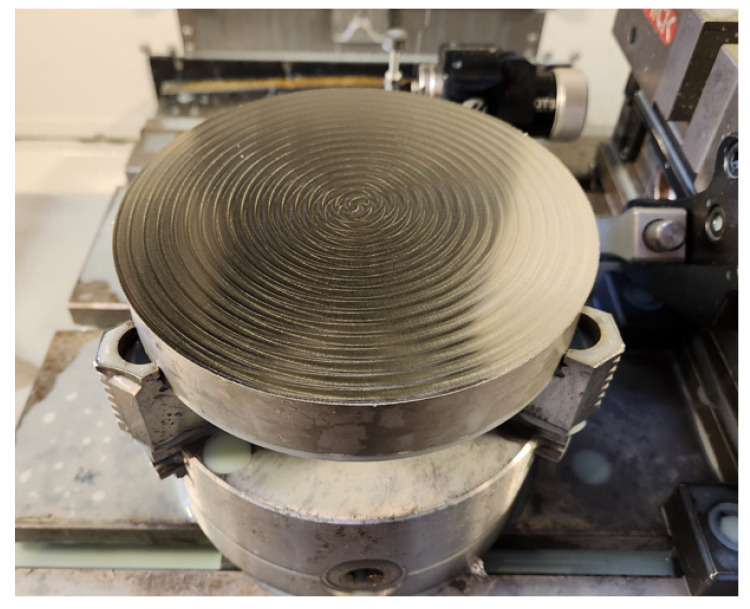
Regarding the milling parameters, because the strategy chosen was a spiral to avoid wear-related phenomena, the radial depth of the cut was kept constant. Another parameter was the axial depth of the cut (ap, or ADOC). This parameter was suggested by the cutting tool supplier, therefore, initially, values of 0.2 mm and 0.1 mm were applied. However, these values caused the tool to fail and break shortly after the initial plunge. Due to this, the value of 0.08 mm was defined for this parameter, which was kept constant for all tests, as finishing milling operations was the goal to simulate. In addition, as the tool Ø = 6 mm, the value of the radial depth of cut (ae or RDOC) was defined considering 75% of this value, i.e., 4.5 mm. This parameter also remained constant for all conditions tested. The parameters vc, fz, and Lcut were varied, determined based on the provided substrate of the tool. Regarding fz, the centre value (100%) was 0.0700 mm/tooth and varied by 25% for less and 50% for more. This parameter was varied as it is known to have a high impact on wear and influence the quality of the machined surface. For Lcut, values of 5 m and 15 m were selected, aiming to analyse the progression of wear throughout the machining of the workpiece. For vc, values of 75, 100, and 125 m/min were used, with the purpose of comparing and analysing the influence of cutting speed on the resulting wear and surface integrity. All parameters and test conditions are shown in Table 5, and Figure 1 illustrates the workpiece with its corresponding spiral marks. To fix this workpiece, a self-centring bushing with three jaws, Bison 3575 (BISON-BIAL, Bliesk Podiaski, Poland), was used, and the tools were fixed with an ISO40 DIN69871 cone, an ER32 H70 collet holder, an ISO 7388-2 tie rod, and an ER DIN 6499 collet from the same manufacturer.
Table 5.
Parameters and conditions used in milling tests.
| Reference |
vc [m/min] |
fz [mm/tooth] | Lcut [m] | ap [mm] | ae [mm] | T [min] |
|---|---|---|---|---|---|---|
| S75F75L5 | 75.0000 | 0.0525 | 5.0000 | 0.0800 | 4.5000 | 5.9854 |
| S75F75L15 | 75.0000 | 0.0525 | 15.0000 | 0.0800 | 4.5000 | 17.9563 |
| S75F100L5 | 75.0000 | 0.0700 | 5.0000 | 0.0800 | 4.5000 | 4.4880 |
| S75F100L15 | 75.0000 | 0.0700 | 15.0000 | 0.0800 | 4.5000 | 13.4640 |
| S75F150L5 | 75.0000 | 0.1050 | 5.0000 | 0.0800 | 4.5000 | 2.9919 |
| S75F150L15 | 75.0000 | 0.1050 | 15.0000 | 0.0800 | 4.5000 | 8.9759 |
| S100F75L5 | 100.0000 | 0.0525 | 5.0000 | 0.0800 | 4.5000 | 4.4880 |
| S100F75L15 | 100.0000 | 0.0525 | 15.0000 | 0.0800 | 4.5000 | 13.4639 |
| S100F100L5 | 100.0000 | 0.0700 | 5.0000 | 0.0800 | 4.5000 | 3.3659 |
| S100F100L15 | 100.0000 | 0.0700 | 15.0000 | 0.0800 | 4.5000 | 10.0978 |
| S100F150L5 | 100.0000 | 0.1050 | 5.0000 | 0.0800 | 4.5000 | 2.2440 |
| S100F150L15 | 100.0000 | 0.1050 | 15.0000 | 0.0800 | 4.5000 | 6.7319 |
| S125F75L5 | 125.0000 | 0.0525 | 5.0000 | 0.0800 | 4.5000 | 3.5904 |
| S125F75L15 | 125.0000 | 0.0525 | 15.0000 | 0.0800 | 4.5000 | 10.7711 |
| S125F100L5 | 125.0000 | 0.0700 | 5.0000 | 0.0800 | 4.5000 | 2.6928 |
| S125F100L15 | 125.0000 | 0.0700 | 15.0000 | 0.0800 | 4.5000 | 8.0783 |
| S125F150L5 | 125.0000 | 0.1050 | 5.0000 | 0.0800 | 4.5000 | 1.7952 |
| S125F150L15 | 125.0000 | 0.1050 | 15.0000 | 0.0800 | 4.5000 | 5.3856 |
Figure 1.
Workpiece material and its spiral marks.
2.2.3. Machined SR Analysis
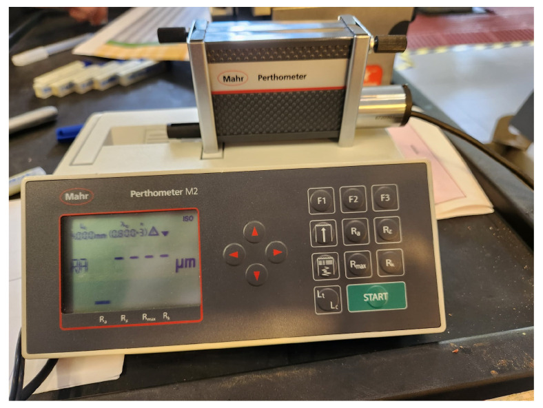
Regarding the roughness of the machined surface, this was measured using a Mahr Perthometer M2 profilometer (Mahr, Gottingen, Germany) (Figure 2). The test was carried out following DIN EN ISO 21920-3:2021 [57]. Each test was performed with a cut-off value (λc) of 0.8 mm and a measurement length of 5.6 mm. Moreover, as errors may occur due to the acceleration and deceleration of the probe at the time of measurement, the first and last measurement segments of 0.8 mm were not considered. In addition, measurements were taken in the radial and tangential directions, and a minimum of five measurements were taken in different areas due to the possibility of variation in the values obtained in the centre and on the periphery of the workpiece. With these, the arithmetic average roughness value (Ra) was determined.
Figure 2.
Mahr Perthometer M2 profilometer.
Thus, roughness analysis was performed to evaluate the process stability and performance of the cutting tool, which can be related to TW and the best milling conditions for which it is possible to obtain the best quality and surface integrity.
2.2.4. Characterisation of Wear Mechanisms
Before analysing the cutting tools’ wear, they underwent ultrasonic cleaning with acetone as a cleaning agent. Afterwards, the wear suffered by the machining tools was evaluated through Scanning Electron Microscopy (SEM) analysis, according to ISO 8688-2:1986 [58]. This standard recommends analysing the presence of all wear phenomena and adopting the one with the most significant influence as a life criterion. Thus, the VB3 was selected, and the wear measurements were performed in “Position 1”. For this, an FEI QUANTA 400 FEG scanning electron microscope was used (F.E.I., Hillsboro, OR, USA), equipped with an EDAX Genesys Energy Dispersive X-Ray Spectroscopy microanalysis system (EDAX Inc., Mahwah, NJ, USA). The analyses were carried out using BackScattered Electrons Diffraction (BSED), with magnification varying between 100× and 2000×, and using a beam potential of 15 kV, which was sporadically reduced to 10 kV.
Furthermore, Energy-Dispersive X-Ray Spectroscopy (EDS) (EDAX Inc., Mahwah, NJ, USA) analysis was used to check and confirm the occurrence of material adhered to the tool. The top view (TOP), rake face (RF), and clearance face (CF) of all tools were analysed. In addition, for better identification, a reference was created for the four cutting teeth of the tool, with numbers 1 to 4 used to identify them.
3. Results and Discussion
3.1. Roughness Analysis of the Machined Surface
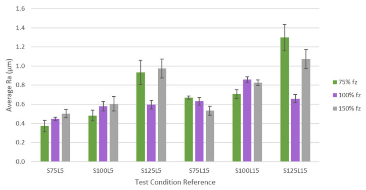
The SR was measured after each tested condition to analyse the machined surface quality in the tangential and radial directions. No notable differences were observed between the values obtained in different directions. All test conditions were compared using the SR values obtained, which were organised and grouped according to Figure 3 and are shown in Table 6. The figure is divided by test conditions in the graph’s X axis and three groups corresponding to each fz, as a percentage of the initial value (0.07 mm/tooth). SR values are displayed according to the Y axis. It should be noted that, according to the identification of the tools, the number after the “S” indicates the vc and the number after the “L” indicates the Lcut used in the machining test.
Figure 3.
Comparison of SR values obtained for all conditions tested.
Table 6.
Ra values for all conditions tested.
| Reference | Average Ra Value (µm) |
|---|---|
| S75F75L5 | 0.372 ± 0.0060 |
| S75F75L15 | 0.670 ± 0.0155 |
| S75F100L5 | 0.448 ± 0.0176 |
| S75F100L15 | 0.631 ± 0.0382 |
| S75F150L5 | 0.502 ± 0.0434 |
| S75F150L15 | 0.533 ± 0.0472 |
| S100F75L5 | 0.483 ± 0.0542 |
| S100F75L15 | 0.708 ± 0.0444 |
| S100F100L5 | 0.578 ± 0.0493 |
| S100F100L15 | 0.859 ± 0.0301 |
| S100F150L5 | 0.605 ± 0.0755 |
| S100F150L15 | 0.827 ± 0.0279 |
| S125F75L5 | 0.935 ± 0.1270 |
| S125F75L15 | 1.299 ± 0.2759 |
| S125F100L5 | 0.595 ± 0.0454 |
| S125F100L15 | 0.659 ± 0.0431 |
| S125F150L5 | 0.975 ± 0.0988 |
| S125F150L15 | 1.073 ± 0.0999 |
It can be seen that by increasing the Lcut, the SR values also increased, which was an already expected result, as Inconel 718 is a difficult-to-machine material that, even for small Lcut values, can generate high levels of TW, and, consequently, greater SR values and a poorer quality of the machined surface [59].
The influence of the fz is not evident for the conditions tested at a vc = 75 m/min since for a Lcut = 5 m, when the fz increased, the roughness also increased. On the other hand, for a Lcut = 15 m, when the fz was increased, the SR decreased. Usually, for lower values of fz, the quality of the machined surface is better, i.e., the roughness of the machined surface has lower values [60], meaning that the quality of the machined surface could be impaired with the increase in fz [56]. However, for conditions with a Lcut = 15 m, this scenario was not observed since there was an improvement in the surface quality obtained. This could have been generated by stabilising the wear behaviour on the tool’s cutting edge, homogenising the wear effect on the edge.
Therefore, under the conditions tested at a vc = 75 m/min, the maximum value of Ra was obtained for the condition that used 75% fz and a Lcut = 15 m, i.e., for condition S75F75L15. The lowest Ra value was obtained for the condition with 75% fz and a Lcut = 5 m, corresponding to the S75F75L5 condition. Thus, it can be seen that for 75% fz, when increasing the Lcut from 5 m to 15 m, the difference in roughness was the most notable among the tested conditions.
In the same way as for the conditions tested at 75 m/min, under the conditions tested at 100 m/min, when the Lcut was increased, the roughness also increased, making this parameter’s influence evident. Furthermore, for a Lcut = 5 m, the same was observed as in the previous case: when the fz increased, the roughness of the machined surface also increased. However, for a Lcut = 15 m, when increasing the fz from 75% to 100%, the roughness increased significantly, and when increasing the fz to 150%, the roughness decreased slightly compared to 100% fz. Therefore, by increasing the fz, the roughness of the machined surface tends to be worse. Thus, it appears that this parameter greatly influences the roughness of the machined surface [61].
In the same way as in the conditions at 75 m/min and 100 m/min, in the case of using 125 m/min, when increasing the Lcut from 5 m to 15 m, the SR also increases. Regarding the fz, there seems to be some instability in the process under conditions at 75% of this parameter, given the discrepancy in the values obtained. However, for 100% and 150% of this parameter, for both 5 m and 15 m, it is observed that when the parameter increases, the roughness also increases, and the quality of the machined surface decreases.
In general, it can be seen that average Ra values tend to increase for higher Lcut values, a trend that is registered for all conditions tested. In some conditions, this increase is more pronounced, as is the case in conditions S75F75, S100F100, and S125F75. On the other hand, this increase is slight in some conditions, for example, in conditions S75F150, S125F100, and S125F150.
Regarding the fz, it is observed that this parameter also influences the roughness of the machined surface [62], but this influence is not so evident, as a common trend is not observed across all conditions. Therefore, when comparing this parameter, it is clear that for conditions S75L5 and S100L5, increasing this parameter worsens the quality of the machined surface. For the S75L15 condition, increasing this parameter results in a lower SR. On the other hand, for conditions S125L5 and S125L15, a decrease in roughness was observed when increasing from 75% of this parameter to 100%, followed by an increase in roughness when increasing to 150% of the fz. For the S100L15 condition, the opposite occurred: the roughness increased, followed by a decrease, when varying the fz. However, in general, increasing the fz increases the roughness of the surface [63].
Furthermore, concerning the vc, it is observed that the higher this parameter, the more the roughness of the machined surface rises and the lower the surface quality. This is not commonly observed, as the tendency is for SR to decrease as this parameter increases [64]. This phenomenon probably occurred because Inconel 718 is a material that is difficult to machine, the amount of wear suffered at these vcs was high, and high abrasive wear was usually observed, which can lead to cutting tool chipping [65]. The only case in which it was observed that by increasing the vc the Ra was lower was for 100% fz, with a Lcut = 15 m, when increasing the vc from 100 m/min to 125 m/min.
As for standard deviation (SD), it is known that this refers to the difference in measurements at the centre and periphery of the part. In the latter, the measurement tends to be higher, as it is the end of the spiral path, and, consequently, the wear is also higher. Conditions S125F75L5 and S125F75L15 showed a more significant SD. These two conditions, as previously mentioned, suffered from instability in the process. However, this higher SD result may be related to the sustained abrasive wear of the tool, which can lead to a difference in the SR recorded from the centre to the periphery of the part [66].
For a more concise and accurate validation, t-tests for two samples with different variances were conducted on Microsoft® Excel™ software to statistically assess the differences between the setups while varying a parameter, and to assess whether this parameter was the most influential when moving from one milling setup to another. A p-value of 0.05 was considered significant for the effects. The statistical tests started by comparing Ra results from different Lcut values and verifying the influence of this parameter while fixing s and f; for example, the t-test that compared the Ra from the S75F75L5 setup with the one from the S75F75L15 produced a P(T <= t) two-tailed value of 2 × 10⁻⁴ < 0.05, which means that there is a statistical difference between the two trials’ mean values. Table 7 summarises the aftermath of the statistical tests. All data and statistical results can be found in Appendix A.
Table 7.
Drawn conclusions from the performed t-tests.
| Condition | Comments |
|---|---|
| Lcut influence | For low values of s and f, Lcut has the most influence. However, as the values of s and f increase, its influence on the surface quality becomes less prominent. In the case of S75F150L5 vs. S75F150L15, surface quality is not affected by the Lcut. For cases with conditions S100F150L15 and above, there is a noticeable blend of the influence of all three parameters together. |
| f influence | f is the most influential parameter on the surface quality and this influence is more pronounced when accompanied by an increasing in s within the setup. However, due to phenomena such as three-body abrasion, some outliers are to be seen, since the milling setup has proven to be catastrophic to TiAlYN-coated tools. |
| s influence | s has proven to be the most sensitive parameter, when in conjunction with f and Lcut. In some cases, it is visible that the increase in s leads to a different variance in the measured values, but sometimes it does not. Nonetheless, for the most extreme setups carried out, s is a very influential parameter regarding surface quality. |
In general, it can be said that the quality of the machined surface was satisfactory, with good SR results. The exceptions were conditions S125F75L5 and S125F75L15, which experienced instability during the process, and, consequently, their results were discrepant. One of the main characteristics of surface integrity is the presence of compressive residual stresses [67], which are generated through the HiPIMS deposition technique [68] and which also prevent cohesive failures [69]. This fact is very beneficial for producing a machined surface with low roughness and a good surface quality to the machined part [56].
3.2. Wear Measurements and Characterisation
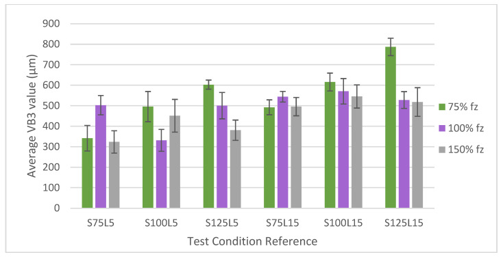
As explained in Section 2.2.4, the TW measurement was carried out following ISO 8688-2:1986 [58] for the top view of the tools (VB3). To compare all test conditions, the values obtained for VB3 were organised and grouped according to Figure 4; the sum is shown in Table 8. Figure 2 is divided by test conditions in the X axis of the graph, with three groups corresponding to each fz, as a percentage of the initial value (0.07 mm/tooth) in the Y axis. It should be noted that, according to the identification of the tools, the number after the “S” indicates the vc and the number after the “L” indicates the Lcut used in the machining test.
Figure 4.
Comparison of VB3 values obtained for all conditions tested.
Table 8.
Average values of VB3 for all conditions tested.
| Reference | Average VB3 Value (µm) |
|---|---|
| S75F75L5 | 341.67 ± 124.349 |
| S75F75L15 | 492.15 ± 72.7340 |
| S75F100L5 | 502.68 ± 94.3731 |
| S75F100L15 | 543.75 ± 25.8692 |
| S75F150L5 | 323.43 ± 109.361 |
| S75F150L15 | 495.38 ± 89.2471 |
| S100F75L5 | 495.77 ± 147.663 |
| S100F75L15 | 615.55 ± 43.5210 |
| S100F100L5 | 331.09 ± 106.354 |
| S100F100L15 | 570.41 ± 62.1473 |
| S100F150L5 | 450.84 ± 79.8641 |
| S100F150L15 | 545.21 ± 56.4712 |
| S125F75L5 | 602.74 ± 22.1942 |
| S125F75L15 | 786.95 ± 85.0253 |
| S125F100L5 | 500.13 ± 128.609 |
| S125F100L15 | 527.68 ± 41.0967 |
| S125F150L5 | 380.68 ± 98.4872 |
| S125F150L15 | 518.06 ± 70.0723 |
For conditions tested at a vc = 75 m/min, the influence of the Lcut is evidently clear when the Lcut increases from 5 m to 15 m. However, at 100% fz, this increase was slightly higher. Regarding the influence of the variation in the fz on the flank wear (VB as ISO 8688-2:1986 [58] of the tools, for a Lcut = 5 m the lowest value obtained was for condition S75F150L5. Wear increased when increasing the fz from 75% to 100% and decreased when increasing to 150%. In turn, the same trend was observed for the cases tested at a Lcut = 15 m; increased wear from 75% to 100% fz, and a reduction as the increase continued to 150%. At 100% fz, and a Lcut = 15 m, the maximum VB was observed. It was also noted that the condition of a Lcut = 5 m and 100% fz presented greater wear than conditions with a Lcut = 15 m and 150% fz.
For conditions tested at 100 m/min, the same situation as in the previous case is observed regarding the Lcut. When increasing from 5 m to 15 m, the resulting VB3 is higher. This is due to the properties of Inconel 718, such as the thermomechanical tool load, which generates high abrasive damage [65]. However, no clear influence of the fz parameter is observed. For a Lcut = 5 m, when increasing from 75% to 100% fz, the VB3 decreases, and when increasing it to 150%, the VB3 increases, but with a lower value than in the first condition (F75L5). On the other hand, for a Lcut = 15 m, when the fz is increased, the VB3 decreases in all fz conditions.
The fact that a common trend for fz is not observed may be related to the chip formation mechanism, which varies under each condition and is related to the productivity of the milling process [70]. It seems that the formation of thinner chips is the most common cause of a poor process performance, as they are easier to break, and this causes higher abrasion and, consequently, much wear on the cutting tool. Thus, the chip section should be thicker to lead to greater integrity and extraction flow, but if the thickness is too high it can overload the cutting edge and, consequently, breakage can occur [56].
Under the conditions tested at 125 m/min, the influence of Lcut was also observed. In all conditions, VB3 increased when Lcut increased. This is due to the properties of Inconel 718, which causes abrasive damage and can consequently lead to tool chipping [65]. However, for 100% of the fz, this increase was lessened. Furthermore, the conditions with 75% fz presented the highest VB3, higher for 15 m than the Lcut = 5 m.
Regarding the influence of the fz for a Lcut = 5 m, when the fz was increased, the wear was reduced. The same occurred for a Lcut = 15 m. In other words, under these conditions, when the Lcut was increased, VB3 decreased.
In general, it can be observed that there is no clear trend for fz, making its influence more challenging to analyse and detect. As already mentioned, the fz is directly related to the productivity of the process and the chip formation mechanism. Furthermore, Inconel 718, as a difficult-to-machine material, can generate serrated or segmented chips that affect the machined surface’s integrity [71] and result in different trends for fz.
As for the vc used in each condition, it can be observed that when this parameter is increased in conditions with 75% fz, VB3 also increases. For conditions at 100% fz, a clear trend cannot be identified. Regarding a Lcut = 5 m and 100% fz conditions, wear decreases when increasing from 75 m/min to 100 m/min and increases when increasing to 125 m/min. However, in the last condition, the VB3 is similar to the first condition. In turn, for 150% fz, wear increases when increasing the vc from 75 m/min to 100 m/min and decreases when increasing to 125 m/min at both Lcut values.
Therefore, when the vc is increased, the resulting wear also increases. This increase in VB is in line with the roughness obtained and the quality of the surface of the machined part. But, usually, an increased vc results in a better surface quality and the smoother cutting behaviour of the cutting tools [72].
3.3. Analysis of Wear Mechanisms
3.3.1. vc of 75 m/min
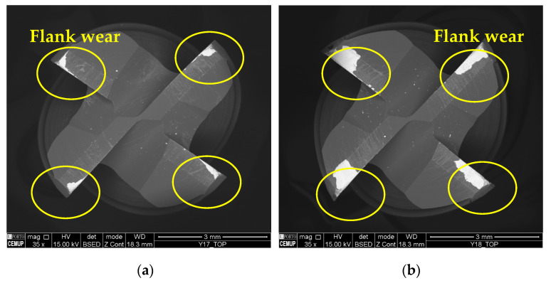
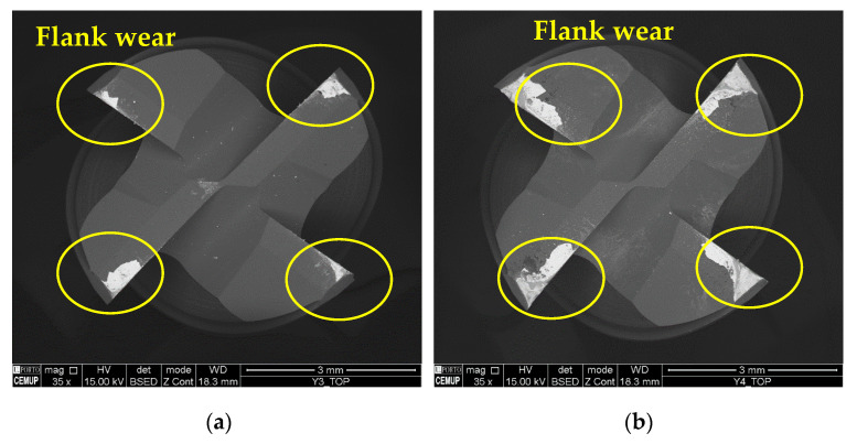
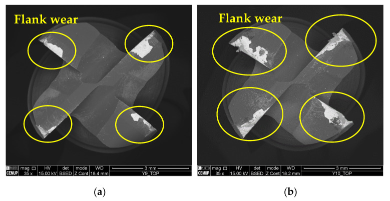
Regarding the type of VB identified for tools tested at 75 m/min, Figure 5 illustrates the top view of the cutting tools tested under conditions S75F150L5 and S75F150L15, making it possible to observe the influence of the Lcut on the resulting wear.
Figure 5.
Top view of the tools tested at a vc of 75 m/min and 35× magnification: (a) S75F150L5 and (b) S75F150L15.
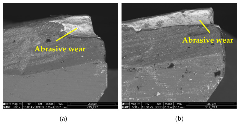
As for the wear mechanism, it can be said that for 75 m/min conditions, mainly abrasion wear and adhesive wear were observed, both on the substrate and on the coating. In addition, in some conditions, delamination and cracking of the coating occurred. Mechanical mechanisms such as abrasion and adhesion are common in terms of the wear suffered by cutting tools in the milling process [73]. Figure 6 illustrates the abrasive wear that occurred on the substrate of the cutting tool under the S75F75L5 and S75F75L15 conditions, where, for 15 m, the wear is more developed. Abrasive wear was detected for all the tests, and was more significant and more intense for the Lcut = 15 m.
Figure 6.
Abrasive wear: (a) clearance face (CF1) of S75F75L5 at 500× magnification and (b) clearance face (CF1) of S75F75L15 at 500× magnification.
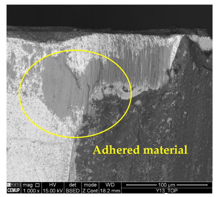
As for the presence of adhered material, it was found in all conditions and in great quantities. This is an expected result, since Inconel 718 usually tends to adhere to cutting tools [74]. Figure 7 illustrates the presence of adhered material on the top view of the S75F75L5 condition.
Figure 7.
Adhered material: top view of S75F75L5 at 1000× magnification.
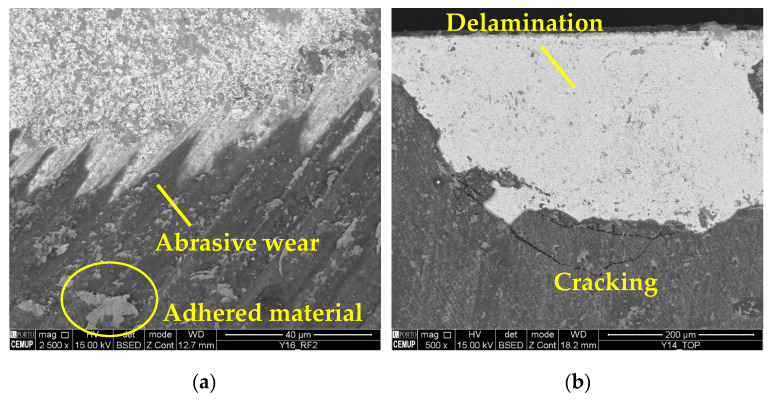
The wear mechanisms identified in the coating were abrasive, workpiece material adhesion, delamination, and cracks. Abrasive and adhesive wear were observed at a lower intensity on the tool substrate. Material adhesion causes more abrasion and can lead to coating delamination [59]. Figure 6 illustrates the wear mechanisms identified in the coating. In Figure 8a, abrasive wear and adhered material can be observed in the S75F100L15 condition, and in Figure 8b, delamination and cracking can be seen in a cutting tool tested in the S75F75L15 condition. Furthermore, it can be stated that the wear mechanisms identified in the cutting tool’s coating were more intense under the conditions tested at the Lcut = 15 m.
Figure 8.
Coating wear mechanisms: (a) abrasive wear and adhered material in the RF2 of the S75F100L15 condition at 2500× magnification and (b) delamination and cracking in the top view of the S75F75L15 condition at 500× magnification.
Thus, it appears that the increase in Lcut caused the development of increased wear mechanisms, such as abrasion and adhesion of the material to the tool surface. It can be said that the adhesion of the material is promoted as the test progresses, as the material accumulates in the grooves left on the tool’s surface as a result of grinding [56]. Therefore, at a longer Lcut, the amount of accumulated material will be higher and, consequently, more abrasive wear will occur, which can lead to coating delamination. Under these conditions, delamination occurred in almost all situations, which also indicates a low adhesion of the coating to the tool substrate. In addition, the lowest wear among all the conditions was for S75F100L5 and S75F150L5, but, as it is the condition with the lowest vc (75 m/min), the machining process was less productive and this could increase the industrial costs.
3.3.2. vc of 100 m/min
Figure 9 illustrates the top view of the S100F100L5 and S100F100L15 conditions, where it is possible to observe the influence of the Lcut on the machining in these conditions.
Figure 9.
Top view of the tools tested at a vc of 100 m/min at 35× magnification: (a) S100F100L5 and (b) S100F100L15.
As mentioned, the impact of the Lcut seems to significantly increase the resulting wear, as can be seen from the measurements carried out and clearly seen in the images obtained. As for the influence of fz, due to the frictional wear to which the tool is subject at lower values of this parameter [75], the wear mark is broader for tools tested with a lower fz, i.e., wear is more pronounced and deeper than in tools tested with higher values. This can modify the geometry of the tools and is also related to the chip generation process [17].
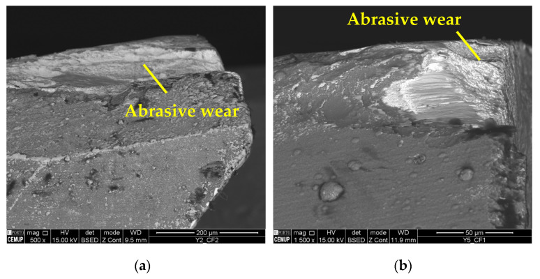
The predominant wear mechanisms on the tool substrate and coating were abrasion and material adhesion, the latter being more intense than in the cases tested at 75 m/min. It is seen that Inconel 718 commonly adheres to cutting tools [74]. The abrasive wear was more intense on the clearance face of the tools, as shown in Figure 10, and this type of wear is frequent when machining this alloy [76].
Figure 10.
Abrasive wear: (a) clearance face (CF2) of S100F75L15 at 500× magnification and (b) clearance face (CF1) of S100F150L5 at 1500× magnification.
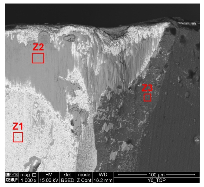
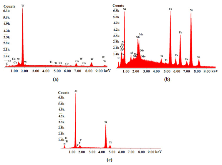
Figure 11 illustrates the adhesion of the material to the tool substrate under the S100F150L15 condition, and three zones in which the analysis was carried out. This wear was registered on the tools’ flank, edges, and rake face. In this case, EDS analysis was performed to confirm that it was Inconel 718, according to the chemical composition resulting from the analysis. Figure 12 illustrates the results of the EDS analysis for the three corresponding zones.
Figure 11.
Condition S100F150L15 indicates material adhesion and has three zones for EDS analysis.
Figure 12.
EDS spectra analysis of the three zones of S100F150L15: (a) Z1—tool substrate, (b) Z2—adhered machined material, and (c) Z3—coating.
According to the EDS analysis, zone 1, rich in tungsten, refers to the tool substrate; zone 2, in turn, is rich in Ni and with other elements present that are part of the composition of Inconel 718, indicating that it is machined material that is adhered to the substrate of the tool; and zone 3, indicating the constituent elements of the coating. Therefore, the coherence of the results obtained, based on the chemical composition of the areas indicated in the image, can be observed.
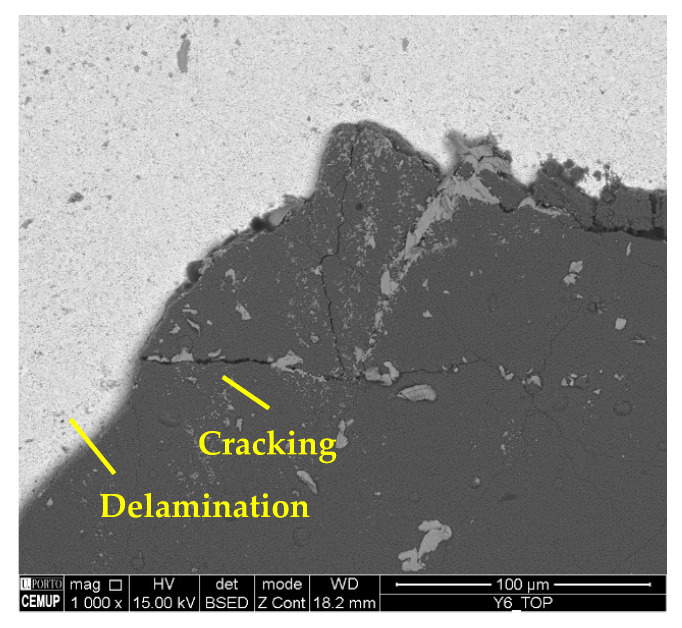
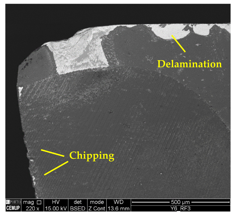
Regarding the wear mechanisms identified in the coating, delamination, chipping, and cracking can also be observed in addition to material adhesion and abrasion. Figure 13 illustrates cracking and delamination identified on the coating, and Figure 14 the chipping and delamination as well. This chipping may negatively affect process performance [77] due to the change in the cutting tool’s geometry [78]. Another aspect is related to cracking propagation. Some authors, such as Zhang et al. [79] and Shuai et al. [80], suggest that the presence of an interlayer could provide high strength to the coating, and that, with this, the resistance to crack propagation increases. Furthermore, thinner layers significantly increase the resistance to crack propagation and protect the coating from delamination, improving its adhesion [81,82].
Figure 13.
Delamination and cracking in the top view of S100F150L15 at 1000× magnification.
Figure 14.
Delamination and chipping in RF3 of S100F150L15 at 220× magnification.
3.3.3. vc of 125 m/min
Figure 15 illustrates the top view of two tools tested at 125 m/min under the S125F100L5 and S125F100L15 conditions. As seen in Section 3.3.2. the difference between these two conditions was not pronounced regarding VB3, even when the vc increased. It can be observed that the maximum TW was similar, but in the 15 m condition it was more significant and expanded towards the centre of the cutting tool. However, in other conditions, as expected, the severity of the wear increased for higher values of Lcut, which further intensified the wear phenomena.
Figure 15.
Top view of the tools tested at a vc of 125 m/min at 35× magnification: (a) S125F100L5 and (b) S125F100L15.
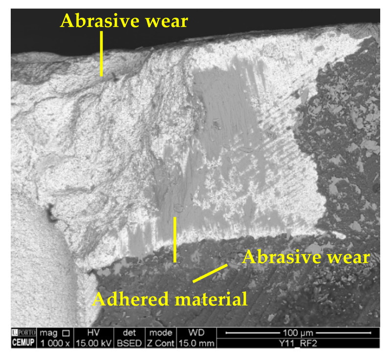
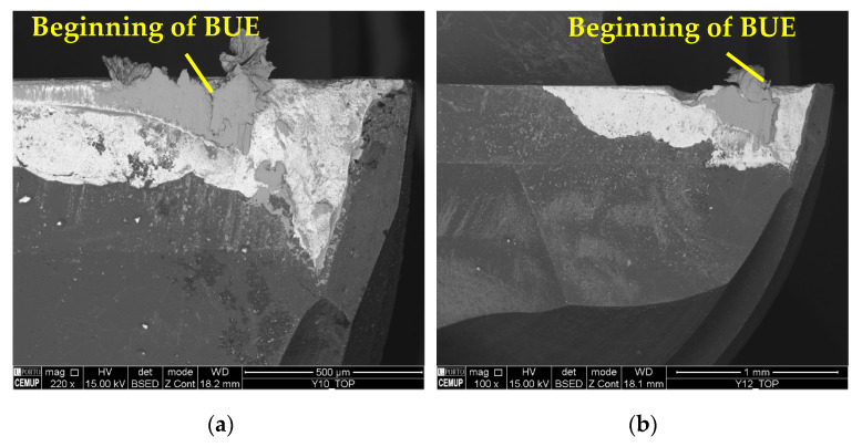
As in previous cases, the main wear mechanisms observed were abrasion and adhesion. However, under these conditions, the wear was higher and more expressive, with the beginning of the development of a BUE under the conditions tested at a Lcut = 15 m. The beginning of the development of a BUE indicates a large amount of adhered material, which tends to generate severe wear [83], as this mechanism increases abrasive wear and, consequently, leads to the occurrence of the delamination of the coating. Figure 16 illustrates the abrasive wear and material adhesion, both on the coating and the tool substrate, and Figure 17 illustrates the beginning of BUE development.
Figure 16.
Wear mechanisms in condition S125F150L5: abrasive and adhesive wear on the tool substrate and coating.
Figure 17.
Beginning of BUE development: (a) top view of S125F100L15 with 220× magnification and (b) top view of S125F150L15 with 100× magnification.
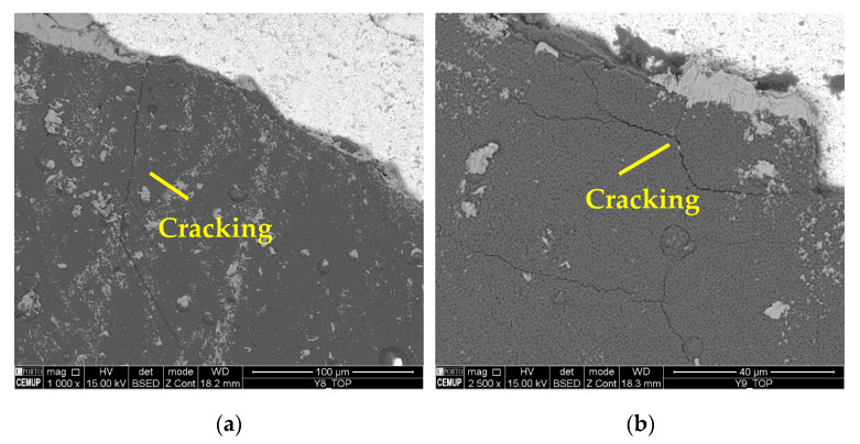
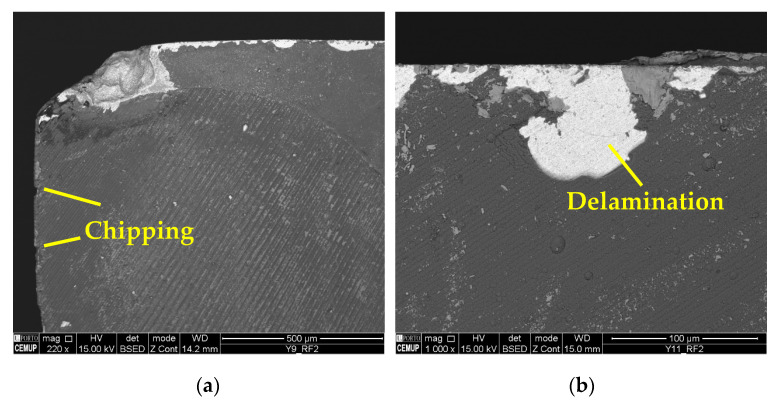
It should be noted that the BUE is more common at a lower vc, and changes the tool’s geometry, which can accelerate TW [59]. The machining of Inconel 718 can be reasonably aggressive on cutting tools, promoting high levels of wear [76]. Furthermore, cracking, chipping, and delamination were observed in the coating. The formation of chips impairs the performance of the machining process, as this type of wear changes the geometry of the cutting tools, which causes the chip generation mechanisms to be modified, and consequently, the quality of the product obtained is lower [84]. Figure 18 illustrates the cracks in the coating seen under the S125F75L15 and S125F100L5 conditions, and Figure 19 illustrates chipping (S125F100L5) and delamination (S125F150L5).
Figure 18.
Cracking in the coating: (a) top view of S125F75L15 at 1000× magnification and (b) top view of S125F100L5 at 2500× magnification.
Figure 19.
Coating wear mechanisms: (a) chipping in RF2 of S125F100L5 condition at 220× magnification and (b) delamination in RF2 of S125F150L5 condition at 1000× magnification.
From the wear mechanisms identified, the difficulty of milling operations with Inconel 718 can be seen. But not only Inconel 718 brings this difficulty, which results in severe wear mechanisms; authors such as Martinho et al. [85] have analysed and detected similar mechanisms as a result of the machining of other materials that are also considered difficult to machine.
4. Conclusions
The present work describes a comparative evaluation of milling parameters regarding their influence on the quality of the machined surface and the resulting tool wear. Machining parameters such as vc, fz, and Lcut were altered for this evaluation. Regarding the results obtained, the following conclusions can be drawn:
The machining parameters influence the process, with the Lcut having the highest influence;
The lowest roughness values for the machined surface were obtained using the S75F75L5 condition;
Due to sustained TW, the vc had no apparent influence on roughness;
Regarding the SD observed in SR measurements, it can be stated that the change in the measurements from the centre to the periphery of different conditions was induced by the increased TW observed during the path followed by the tool for the machining strategy adopted;
The greatest VB was observed for the S125F75L15 condition, and the lowest for the S75F150L5 condition, which were clearly influenced by the Lcut;
For higher vc and Lcut values, the wear developed was more intense;
The predominant wear mechanisms were abrasive and adhesive wear on the coating and the tool substrate. Delamination, chipping, and cracking were also observed in the coated tools;
At a Lcut of 15 m and vc of 125 m/min, BUE development was generated;
Even at a Lcut = 5 m, much wear was observed, which indicates the difficulty of machining Inconel 718, leading to the realisation that these cutting tools are unsuitable for these kinds of operations with higher Lcut values.
Therefore, the results show a need to improve the process further, especially regarding the high wear on the coating. The coatings’ adhesion must also be improved, since coating delamination was observed under all conditions. Therefore, adding an interlayer before applying the coating now used is suggested, with the aim to improve its adhesion and reduce cracking propagation, consequently improving the process performance. Furthermore, the wear behaviour of this coating in cutting tools of different geometries can be compared with the results obtained in this work. Moreover, the results clearly indicate the need for a new study focused on the coating deposition parameters and the optimisation of machining parameters.
In addition, as a limitation of this study, the difficulty of machining Inconel 718 is highlighted, as well as the use of few machining conditions, making it necessary to expand them so that this analysis would be more complete. Based on this, for future work we recommend the use of more samples and machining conditions, as well as the use of a interlayer coating in order to avoid delamination, and the comparison of this coating’s behaviour with other coatings and with uncoated tools. In addition, we recommend carrying out a statistical analysis of the results obtained.
Acknowledgments
The authors thank ISEP, INEGI, and FEUP for their institutional support. The authors also acknowledge Rui Rocha from CEMUP Lab due to his contribution on the SEM analyses and interpretation, and to Ricardo Alexandre from INOVATOOLS company due to his availability to provide free of charge the tools used in this work, as well as Victor Moreira due to his collaboration in machining tests.
Appendix A
Here lies the statistical analysis on the influence of each parameter on surface quality.
Table A1.
t-test: two samples with different variances, comparison between their Lcut values, part 1.
| S75F75L5 | S75F75L15 | S75F100L5 | S75F100L15 | S75F150L5 | S75F150L15 | S100F75L5 | S100F75L15 | S100F100L5 | S100F100L15 | S100F150L5 | S100F150L15 | |
|---|---|---|---|---|---|---|---|---|---|---|---|---|
| Mean | 0.372 | 0.670 | 0.448 | 0.631 | 0.502 | 0.533 | 0.483 | 0.708 | 0.578 | 0.859 | 0.605 | 0.827 |
| Variance | 0.005 | 0.000 | 0.000 | 0.002 | 0.002 | 0.003 | 0.004 | 0.002 | 0.003 | 0.001 | 0.007 | 0.001 |
| Observations | 5 | 5 | 5 | 5 | 5 | 5 | 5 | 5 | 5 | 5 | 5 | 5 |
| Hypothesised mean Difference |
0 | 0 | 0 | 0 | 0 | 0 | ||||||
| df | 5 | 6 | 8 | 8 | 7 | 5 | ||||||
| t Stat | −9.612 | −8.683 | −0.954 | −6.430 | −9.728 | −5.501 | ||||||
| P(T <= t) one-tail | 0.000 | 0.000 | 0.184 | 0.000 | 0.000 | 0.001 | ||||||
| t critical one-tail | 2.015 | 1.943 | 1.860 | 1.860 | 1.895 | 2.015 | ||||||
| P(T <= t) two-tail | 0.000 | 0.000 | 0.368 | 0.000 | 0.000 | 0.003 | ||||||
| t critical two-tail | 2.571 | 2.447 | 2.306 | 2.306 | 2.365 | 2.571 |
Table A2.
t-Test: two samples with different variances, comparison between their Lcut values, part 2.
| S125F75L5 | S125F75L15 | S125F100L5 | S125F100L15 | S125F150L5 | S125F150L15 | |
|---|---|---|---|---|---|---|
| Mean | 0.935 | 1.299 | 0.595 | 0.659 | 0.975 | 1.073 |
| Variance | 0.020 | 0.095 | 0.003 | 0.002 | 0.012 | 0.012 |
| Observations | 5 | 5 | 5 | 5 | 5 | 5 |
| Hypothesised mean Difference |
0 | 0 | 0 | |||
| df | 6 | 8 | 8 | |||
| t Stat | −2.398 | −2.039 | −1.392 | |||
| P(T <= t) one-tail | 0.027 | 0.038 | 0.101 | |||
| t critical one-tail | 1.943 | 1.860 | 1.860 | |||
| P(T <= t) two-tail | 0.053 | 0.076 | 0.201 | |||
| t critical two-tail | 2.447 | 2.306 | 2.306 |
Table A3.
t-Test: two samples with different variances, comparison between their f values, part 1.
| S75F75L5 | S75F100L5 | S75F75L15 | S75F100L15 | S100F75L5 | S100F100L5 | S100F75L15 | S100F100L15 | S125F75L5 | S125F100L5 | S125F75L15 | S125F100L15 | |
|---|---|---|---|---|---|---|---|---|---|---|---|---|
| Mean | 0.372 | 0.448 | 0.670 | 0.631 | 0.483 | 0.578 | 0.708 | 0.859 | 0.935 | 0.595 | 1.299 | 0.659 |
| Variance | 0.005 | 0.000 | 0.000 | 0.002 | 0.004 | 0.003 | 0.002 | 0.001 | 0.020 | 0.003 | 0.095 | 0.002 |
| Observations | 5 | 5 | 5 | 5 | 5 | 5 | 5 | 5 | 5 | 5 | 5 | 5 |
| Hypothesised Mean Difference |
0 | 0 | 0 | 0 | 0 | 0 | ||||||
| df | 5 | 5 | 8 | 7 | 5 | 4 | ||||||
| t Stat | −2.435 | 1.891 | −2.592 | −5.614 | 5.036 | 4.584 | ||||||
| P(T <= t) one-tail | 0.029 | 0.059 | 0.016 | 0.000 | 0.002 | 0.005 | ||||||
| t critical one-tail | 2.015 | 2.015 | 1.860 | 1.895 | 2.015 | 2.132 | ||||||
| P(T <= t) two-tail | 0.059 | 0.117 | 0.032 | 0.001 | 0.004 | 0.010 | ||||||
| t critical two-tail | 2.571 | 2.571 | 2.306 | 2.365 | 2.571 | 2.776 |
Table A4.
t-Test: two samples with different variances, comparison between their f values, part 2.
| S75F100L5 | S75F150L5 | S75F100L15 | S75F150L15 | S100F100L5 | S100F150L5 | S100F100L15 | S100F150L15 | S125F100L5 | S125F150L5 | S125F100L15 | S125F150L15 | |
|---|---|---|---|---|---|---|---|---|---|---|---|---|
| Mean | 0.448 | 0.502 | 0.631 | 0.533 | 0.578 | 0.605 | 0.859 | 0.827 | 0.595 | 0.975 | 0.659 | 1.073 |
| Variance | 0.000 | 0.002 | 0.002 | 0.003 | 0.003 | 0.007 | 0.001 | 0.001 | 0.003 | 0.012 | 0.002 | 0.012 |
| Observations | 5 | 5 | 5 | 5 | 5 | 5 | 5 | 5 | 5 | 5 | 5 | 5 |
| Hypothesised Mean Difference |
0 | 0 | 0 | 0 | 0 | 0 | ||||||
| df | 5 | 8 | 7 | 8 | 6 | 5 | ||||||
| t Stat | −2.295 | 3.238 | −0.608 | 1.571 | −6.987 | −7.607 | ||||||
| P(T <= t) one-tail | 0.035 | 0.006 | 0.281 | 0.077 | 0.000 | 0.000 | ||||||
| t critical one-tail | 2.015 | 1.860 | 1.895 | 1.860 | 1.943 | 2.015 | ||||||
| P(T <= t) two-tail | 0.070 | 0.012 | 0.563 | 0.155 | 0.000 | 0.001 | ||||||
| t critical two-tail | 2.571 | 2.306 | 2.365 | 2.306 | 2.447 | 2.571 |
Table A5.
t-Test: two samples with different variances, comparison between their f values, part 3.
| S75F75L5 | S75F150L5 | S75F75L15 | S75F150L15 | S100F75L5 | S100F150L5 | S100F75L15 | S100F150L15 | S125F75L5 | S125F150L5 | S125F75L15 | S125F150L15 | |
|---|---|---|---|---|---|---|---|---|---|---|---|---|
| Mean | 0.372 | 0.502 | 0.670 | 0.533 | 0.483 | 0.605 | 0.708 | 0.827 | 0.935 | 0.975 | 1.299 | 1.073 |
| Variance | 0.005 | 0.002 | 0.000 | 0.003 | 0.004 | 0.007 | 0.002 | 0.001 | 0.020 | 0.012 | 0.095 | 0.012 |
| Observations | 5 | 5 | 5 | 5 | 5 | 5 | 5 | 5 | 5 | 5 | 5 | 5 |
| Hypothesised Mean Difference |
0 | 0 | 0 | 0 | 0 | 0 | ||||||
| df | 7 | 5 | 7 | 7 | 8 | 5 | ||||||
| t Stat | −3.509 | 5.527 | −2.633 | −4.514 | −0.500 | 1.542 | ||||||
| P(T <= t) one-tail | 0.005 | 0.001 | 0.017 | 0.001 | 0.315 | 0.092 | ||||||
| t critical one-tail | 1.895 | 2.015 | 1.895 | 1.895 | 1.860 | 2.015 | ||||||
| P(T <= t) two-tail | 0.010 | 0.003 | 0.034 | 0.003 | 0.631 | 0.184 | ||||||
| t critical two-tail | 2.365 | 2.571 | 2.365 | 2.365 | 2.306 | 2.571 |
Table A6.
t-Test: two samples with different variances, comparison between their s values, part 1.
| S75F75L5 | S100F75L5 | S75F75L15 | S100F75L15 | S75F100L5 | S100F100L5 | S75F100L15 | S100F100L15 | S75F150L5 | S100F150L5 | S75F150L15 | S100F150L15 | |
|---|---|---|---|---|---|---|---|---|---|---|---|---|
| Mean | 0.372 | 0.483 | 0.670 | 0.708 | 0.448 | 0.578 | 0.631 | 0.859 | 0.502 | 0.605 | 0.533 | 0.827 |
| Variance | 0.005 | 0.004 | 0.000 | 0.002 | 0.000 | 0.003 | 0.002 | 0.001 | 0.002 | 0.007 | 0.003 | 0.001 |
| Observations | 5 | 5 | 5 | 5 | 5 | 5 | 5 | 5 | 5 | 5 | 5 | 5 |
| Hypothesised Mean Difference |
0 | 0 | 0 | 0 | 0 | 0 | ||||||
| df | 8 | 5 | 5 | 8 | 6 | 6 | ||||||
| t Stat | −2.739 | −1.623 | −4.948 | −9.368 | −2.369 | −10.72 | ||||||
| P(T <= t) one-tail | 0.013 | 0.083 | 0.002 | 0.000 | 0.028 | 0.000 | ||||||
| t critical one-tail | 1.860 | 2.015 | 2.015 | 1.860 | 1.943 | 1.943 | ||||||
| P(T <= t) two-tail | 0.025 | 0.165 | 0.004 | 0.000 | 0.056 | 0.000 | ||||||
| t critical two-tail | 2.306 | 2.571 | 2.571 | 2.306 | 2.447 | 2.447 |
Table A7.
t-Test: two samples with different variances, comparison between their s values, part 2.
| S100F75L5 | S125F75L5 | S100F75L15 | S125F75L15 | S100F100L5 | S125F100L5 | S100F100L15 | S125F100L15 | S100F150L5 | S125F150L5 | S100F150L15 | S125F150L15 | |
|---|---|---|---|---|---|---|---|---|---|---|---|---|
| Mean | 0.483 | 0.935 | 0.708 | 1.299 | 0.578 | 0.595 | 0.859 | 0.659 | 0.605 | 0.975 | 0.827 | 1.073 |
| Variance | 0.004 | 0.020 | 0.002 | 0.095 | 0.003 | 0.003 | 0.001 | 0.002 | 0.007 | 0.012 | 0.001 | 0.012 |
| Observations | 5 | 5 | 5 | 5 | 5 | 5 | 5 | 5 | 5 | 5 | 5 | 5 |
| Hypothesised Mean Difference |
0 | 0 | 0 | 0 | 0 | 0 | ||||||
| df | 5 | 4 | 8 | 7 | 7 | 5 | ||||||
| t Stat | −6.543 | −4.227 | −0.513 | 7.611 | −5.945 | −4.744 | ||||||
| P(T <= t) one-tail | 0.001 | 0.007 | 0.311 | 0.000 | 0.000 | 0.003 | ||||||
| t critical one-tail | 2.015 | 2.132 | 1.860 | 1.895 | 1.895 | 2.015 | ||||||
| P(T <= t) two-tail | 0.001 | 0.013 | 0.622 | 0.000 | 0.001 | 0.005 | ||||||
| t critical two-tail | 2.571 | 2.776 | 2.306 | 2.365 | 2.365 | 2.571 |
Table A8.
t-Test: two samples with different variances, comparison between their s values, part 3.
| S75F75L5 | S125F75L5 | S75F75L15 | S125F75L15 | S75F100L5 | S125F100L5 | S75F100L15 | S125F100L15 | S75F150L5 | S125F150L5 | S75F150L15 | S125F150L15 | |
|---|---|---|---|---|---|---|---|---|---|---|---|---|
| Mean | 0.372 | 0.935 | 0.670 | 1.299 | 0.448 | 0.595 | 0.631 | 0.659 | 0.502 | 0.975 | 0.533 | 1.073 |
| Variance | 0.005 | 0.020 | 0.000 | 0.095 | 0.000 | 0.003 | 0.002 | 0.002 | 0.002 | 0.012 | 0.003 | 0.012 |
| Observations | 5 | 5 | 5 | 5 | 5 | 5 | 5 | 5 | 5 | 5 | 5 | 5 |
| Hypothesised Mean Difference |
0 | 0 | 0 | 0 | 0 | 0 | ||||||
| df | 6 | 4 | 5 | 8 | 5 | 6 | ||||||
| t Stat | −8.009 | −4.551 | −6.031 | −0.965 | −8.762 | −9.774 | ||||||
| P(T <= t) one-tail | 0.000 | 0.005 | 0.001 | 0.181 | 0.000 | 0.000 | ||||||
| t critical one-tail | 1.943 | 2.132 | 2.015 | 1.860 | 2.015 | 1.943 | ||||||
| P(T <= t) two-tail | 0.000 | 0.010 | 0.002 | 0.363 | 0.000 | 0.000 | ||||||
| t critical two-tail | 2.447 | 2.776 | 2.571 | 2.306 | 2.571 | 2.447 |
Author Contributions
Conceptualisation: F.J.G.S., R.C.M.S.-C. and R.P.M.; methodology: N.P.V.S. and R.C.M.S.-C.; validation: F.J.G.S., R.C.M.S.-C. and R.P.M.; formal analysis: R.D.F.S.C., R.C.M.S.-C. and M.L.S.B.; investigation: N.P.V.S. and F.J.G.S.; data curation: N.P.V.S., R.D.F.S.C., M.L.S.B. and F.J.G.S.; writing—original draft preparation: N.P.V.S. and F.J.G.S.; writing—review and editing: A.F.V.P. and F.J.G.S.; visualisation: A.F.V.P., F.J.G.S., R.C.M.S.-C., M.L.S.B. and R.P.M.; supervision: F.J.G.S. and R.C.M.S.-C.; project administration: F.J.G.S.; funding acquisition: F.J.G.S. All authors have read and agreed to the published version of the manuscript.
Data Availability Statement
No new data were created.
Conflicts of Interest
The authors declare no conflicts of interest.
Funding Statement
The work is developed under the “DRIVOLUTION—Transition to the factory of the future”, with the reference DRIVOLUTION C644913740-00000022 research project, supported by European Structural and Investments Funds with the “Portugal2020” program scope.
Footnotes
Disclaimer/Publisher’s Note: The statements, opinions and data contained in all publications are solely those of the individual author(s) and contributor(s) and not of MDPI and/or the editor(s). MDPI and/or the editor(s) disclaim responsibility for any injury to people or property resulting from any ideas, methods, instructions or products referred to in the content.
References
- 1.Qi H., Azer M., Ritter A. Studies of Standard Heat Treatment Effects on Microstructure and Mechanical Properties of Laser Net Shape Manufactured INCONEL 718. Metall. Mater. Trans. A. 2009;40:2410–2422. doi: 10.1007/s11661-009-9949-3. [DOI] [Google Scholar]
- 2.Thomas A., El-Wahabi M., Cabrera J.M., Prado J.M. High Temperature Deformation of Inconel 718. J. Mater. Process Technol. 2006;177:469–472. doi: 10.1016/j.jmatprotec.2006.04.072. [DOI] [Google Scholar]
- 3.Ding R.G., Huang Z.W., Li H.Y., Mitchell I., Baxter G., Bowen P. Electron Microscopy Study of Direct Laser Deposited IN718. Mater. Charact. 2015;106:324–337. doi: 10.1016/j.matchar.2015.06.017. [DOI] [Google Scholar]
- 4.Smith D.H., Bicknell J., Jorgensen L., Patterson B.M., Cordes N.L., Tsukrov I., Knezevic M. Microstructure and Mechanical Behavior of Direct Metal Laser Sintered Inconel Alloy 718. Mater. Charact. 2016;113:1–9. doi: 10.1016/j.matchar.2016.01.003. [DOI] [Google Scholar]
- 5.Zhao X., Chen J., Lin X., Huang W. Study on Microstructure and Mechanical Properties of Laser Rapid Forming Inconel 718. Mater. Sci. Eng. A. 2008;478:119–124. doi: 10.1016/j.msea.2007.05.079. [DOI] [Google Scholar]
- 6.Hosseini E., Popovich V.A. A Review of Mechanical Properties of Additively Manufactured Inconel 718. Addit. Manuf. 2019;30:100877. doi: 10.1016/j.addma.2019.100877. [DOI] [Google Scholar]
- 7.Liu F., Lin X., Song M., Zhao W., Chen J., Huang W. Effect of Intermediate Heat Treatment Temperature on Microstructure and Notch Sensitivity of Laser Solid Formed Inconel 718 Superalloy. J. Wuhan Univ. Technol.-Mater. Sci. Ed. 2011;26:908–913. doi: 10.1007/s11595-011-0335-9. [DOI] [Google Scholar]
- 8.Blackwell P.L. The Mechanical and Microstructural Characteristics of Laser-Deposited IN718. J. Mater. Process Technol. 2005;170:240–246. doi: 10.1016/j.jmatprotec.2005.05.005. [DOI] [Google Scholar]
- 9.Lu Y., Wu S., Gan Y., Huang T., Yang C., Junjie L., Lin J. Study on the Microstructure, Mechanical Property and Residual Stress of SLM Inconel-718 Alloy Manufactured by Differing Island Scanning Strategy. Opt. Laser Technol. 2015;75:197–206. doi: 10.1016/j.optlastec.2015.07.009. [DOI] [Google Scholar]
- 10.Lal Virdi R., Singh Chatha S., Singh H. Performance Evaluation of Inconel 718 under Vegetable Oils Based Nanofluids Using Minimum Quantity Lubrication Grinding. Mater. Today Proc. 2020;33:1538–1545. doi: 10.1016/j.matpr.2020.03.802. [DOI] [Google Scholar]
- 11.Ma L., Zhang L., Guo F., Du W., Luo Y. High-Temperature Mechanical Behavior Assessment Based on a Developed Constitutive Model of Inconel 718 Fabricated by Selective Laser Melting. Adv. Eng. Mater. 2021;23:2100232. doi: 10.1002/adem.202100232. [DOI] [Google Scholar]
- 12.Roy S., Kumar R., Anurag, Panda A., Das R.K. A Brief Review on Machining of Inconel 718. Pt 3Mater. Today Proc. 2018;5:18664–18673. doi: 10.1016/j.matpr.2018.06.212. [DOI] [Google Scholar]
- 13.Outeiro J.C., Pina J.C., M’Saoubi R., Pusavec F., Jawahir I.S. Analysis of Residual Stresses Induced by Dry Turning of Difficult-to-Machine Materials. CIRP Ann. 2008;57:77–80. doi: 10.1016/j.cirp.2008.03.076. [DOI] [Google Scholar]
- 14.Shokrani A., Dhokia V., Newman S.T. Hybrid Cooling and Lubricating Technology for CNC Milling of Inconel 718 Nickel Alloy. Procedia Manuf. 2017;11:625–632. doi: 10.1016/j.promfg.2017.07.160. [DOI] [Google Scholar]
- 15.Ezugwu E.O., Wang Z.M., Okeke C.I. Tool Life and Surface Integrity When Machining Inconel 718 with PVD- and CVD-Coated Tools. Tribol. Trans. 1999;42:353–360. doi: 10.1080/10402009908982228. [DOI] [Google Scholar]
- 16.Pedroso A.F.V., Sousa V.F.C., Sebbe N.P.V., Silva F.J.G., Campilho R.D.S.G., Sales-Contini R.C.M., Jesus A.M.P. A Comprehensive Review on the Conventional and Non-Conventional Machining and Tool-Wear Mechanisms of INCONEL®. Metals. 2023;13:585. doi: 10.3390/met13030585. [DOI] [Google Scholar]
- 17.Sousa V.F.C., Da Silva F.J.G., Pinto G.F., Baptista A., Alexandre R. Characteristics and Wear Mechanisms of TiAlN-Based Coatings for Machining Applications: A Comprehensive Review. Metals. 2021;11:260. doi: 10.3390/met11020260. [DOI] [Google Scholar]
- 18.Sharman A., Dewes R.C., Aspinwall D.K. Tool Life When High Speed Ball Nose End Milling Inconel 718TM. J. Mater. Process Technol. 2001;118:29–35. doi: 10.1016/S0924-0136(01)00855-X. [DOI] [Google Scholar]
- 19.Le Coz G., Dudzinski D. Temperature Variation in the Workpiece and in the Cutting Tool When Dry Milling Inconel 718. Int. J. Adv. Manuf. Technol. 2014;74:1133–1139. doi: 10.1007/s00170-014-6006-1. [DOI] [Google Scholar]
- 20.Çelik A., Sert Alağaç M., Turan S., Kara A., Kara F. Wear Behavior of Solid SiAlON Milling Tools during High Speed Milling of Inconel 718. Wear. 2017;378–379:58–67. doi: 10.1016/j.wear.2017.02.025. [DOI] [Google Scholar]
- 21.Li W., Guo Y.B., Barkey M.E., Jordon J.B. Effect Tool Wear During End Milling on the Surface Integrity and Fatigue Life of Inconel 718. Procedia CIRP. 2014;14:546–551. doi: 10.1016/j.procir.2014.03.056. [DOI] [Google Scholar]
- 22.Feng Y., Pan Z., Liang S.Y. Temperature Prediction in Inconel 718 Milling with Microstructure Evolution. Int. J. Adv. Manuf. Technol. 2018;95:4607–4621. doi: 10.1007/s00170-018-1581-1. [DOI] [Google Scholar]
- 23.Yan S., Zhu D., Zhuang K., Zhang X., Ding H. Modeling and Analysis of Coated Tool Temperature Variation in Dry Milling of Inconel 718 Turbine Blade Considering Flank Wear Effect. J. Mater. Process Technol. 2014;214:2985–3001. doi: 10.1016/j.jmatprotec.2014.07.006. [DOI] [Google Scholar]
- 24.Liao Y.S., Lin H.M., Wang J.H. Behaviors of End Milling Inconel 718 Superalloy by Cemented Carbide Tools. J. Mater. Process Technol. 2008;201:460–465. doi: 10.1016/j.jmatprotec.2007.11.176. [DOI] [Google Scholar]
- 25.Maiyar L.M., Ramanujam R., Venkatesan K., Jerald J. Optimization of Machining Parameters for End Milling of Inconel 718 Super Alloy Using Taguchi Based Grey Relational Analysis. Procedia Eng. 2013;64:1276–1282. doi: 10.1016/j.proeng.2013.09.208. [DOI] [Google Scholar]
- 26.Sebbe N.P.V., Fernandes F., Sousa V.F.C., Silva F.J.G. Hybrid Manufacturing Processes Used in the Production of Complex Parts: A Comprehensive Review. Metals. 2022;12:1874. doi: 10.3390/met12111874. [DOI] [Google Scholar]
- 27.Li H.Z., Zeng H., Chen X.Q. An Experimental Study of Tool Wear and Cutting Force Variation in the End Milling of Inconel 718 with Coated Carbide Inserts. J. Mater. Process Technol. 2006;180:296–304. doi: 10.1016/j.jmatprotec.2006.07.009. [DOI] [Google Scholar]
- 28.Kuo C.-P., Ling C.-C., Chen S.-H., Chang C.-W. The Prediction of Cutting Force in Milling Inconel-718. Int. J. Adv. Manuf. Technol. 2006;27:655–660. doi: 10.1007/s00170-004-2257-6. [DOI] [Google Scholar]
- 29.Mahmood J., Mustafa G., Ali M. Accurate Estimation of Tool Wear Levels during Milling, Drilling and Turning Operations by Designing Novel Hyperparameter Tuned Models Based on LightGBM and Stacking. Measurement. 2022;190:110722. doi: 10.1016/j.measurement.2022.110722. [DOI] [Google Scholar]
- 30.Aslantas K., Alatrushi L.K.H. Experimental Study on the Effect of Cutting Tool Geometry in Micro-Milling of Inconel 718. Arab. J. Sci. Eng. 2021;46:2327–2342. doi: 10.1007/s13369-020-05034-z. [DOI] [Google Scholar]
- 31.Wang J., Yan Y., Li C., Geng Y. Material Removal Mechanism and Subsurface Characteristics of Silicon 3D Nanomilling. Int. J. Mech. Sci. 2023;242:108020. doi: 10.1016/j.ijmecsci.2022.108020. [DOI] [Google Scholar]
- 32.Sahab A.R.M., Saad N.H., Kasolang S., Saedon J. Impact of Plasma Spray Variables Parameters on Mechanical and Wear Behaviour of Plasma Sprayed Al2O3 3%wt TiO2 Coating in Abrasion and Erosion Application. Procedia Eng. 2012;41:1689–1695. doi: 10.1016/j.proeng.2012.07.369. [DOI] [Google Scholar]
- 33.Nogueira F.R., Pedroso A.F.V., Sousa V.F.C., Sebbe N.P.V., Sales-Contini R.C.M., Barbosa M.L.S. A Brief Review of Injection-Mould Materials Hybrid Manufacturing Processes. In: Silva F.J.G., Pereira A.B., Campilho R.D.S.G., editors. Flexible Automation and Intelligent Manufacturing: Establishing Bridges for More Sustainable Manufacturing Systems. Springer Nature; Cham, Switzerland: 2024. pp. 796–806. [Google Scholar]
- 34.Silva F., Martinho R., Andrade M., Baptista A., Alexandre R. Improving the Wear Resistance of Moulds for the Injection of Glass Fibre–Reinforced Plastics Using PVD Coatings: A Comparative Study. Coatings. 2017;7:28. doi: 10.3390/coatings7020028. [DOI] [Google Scholar]
- 35.Ucun İ., Aslantas K., Bedir F. The Performance Of DLC-Coated and Uncoated Ultra-Fine Carbide Tools in Micromilling of Inconel 718. Precis. Eng. 2015;41:135–144. doi: 10.1016/j.precisioneng.2015.01.002. [DOI] [Google Scholar]
- 36.Sousa V.F.C., Silva F.J.G., Alexandre R., Fecheira J.S., Silva F.P.N. Study of the Wear Behaviour of TiAlSiN and TiAlN PVD Coated Tools on Milling Operations of Pre-Hardened Tool Steel. Wear. 2021;476:203695. doi: 10.1016/j.wear.2021.203695. [DOI] [Google Scholar]
- 37.Baptista A., Silva F., Porteiro J., Míguez J., Pinto G. Sputtering Physical Vapour Deposition (PVD) Coatings: A Critical Review on Process Improvement and Market Trend Demands. Coatings. 2018;8:402. doi: 10.3390/coatings8110402. [DOI] [Google Scholar]
- 38.Depla D., Mahieu S., Greene J.E. Chapter 5-Sputter Deposition Processes. In: Martin P.M., editor. Handbook of Deposition Technologies for Films and Coatings. 3rd ed. William Andrew Publishing; Boston, MA, USA: 2010. pp. 253–296. [DOI] [Google Scholar]
- 39.Machunze R., Ehiasarian A.P., Tichelaar F.D., Janssen G.C.A.M. Stress and Texture in HIPIMS TiN Thin Films. Thin Solid. Films. 2009;518:1561–1565. doi: 10.1016/j.tsf.2009.09.069. [DOI] [Google Scholar]
- 40.Ferreira F., Oliveira J.C., Cavaleiro A. CrN Thin Films Deposited by HiPIMS in DOMS Mode. Surf. Coat. Technol. 2016;291:365–375. doi: 10.1016/j.surfcoat.2016.02.064. [DOI] [Google Scholar]
- 41.Alhafian M.-R., Chemin J.-B., Fleming Y., Bourgeois L., Penoy M., Useldinger R., Soldera F., Mücklich F., Choquet P. Comparison on the Structural, Mechanical and Tribological Properties of TiAlN Coatings Deposited by HiPIMS and Cathodic Arc Evaporation. Surf. Coat. Technol. 2021;423:127529. doi: 10.1016/j.surfcoat.2021.127529. [DOI] [Google Scholar]
- 42.Sousa V.F.C., Silva F.J.G., Lopes H., Casais R.C.B., Baptista A., Pinto G., Alexandre R. Wear Behavior and Machining Performance of TiAlSiN-Coated Tools Obtained by Dc MS and HiPIMS: A Comparative Study. Materials. 2021;14:5122. doi: 10.3390/ma14185122. [DOI] [PMC free article] [PubMed] [Google Scholar]
- 43.Mitsuo A., Uchida S., Nihira N., Iwaki M. Improvement of High-Temperature Oxidation Resistance of Titanium Nitride and Titanium Carbide Films by Aluminum Ion Implantation. Surf. Coat. Technol. 1998;103–104:98–103. doi: 10.1016/S0257-8972(98)00380-6. [DOI] [Google Scholar]
- 44.Liew W.Y.H., Lim H.P., Melvin G.J.H., Dayou J., Jiang Z.-T. Thermal Stability, Mechanical Properties, and Tribological Performance of TiAlXN Coatings: Understanding the Effects of Alloying Additions. J. Mater. Res. Technol. 2022;17:961–1012. doi: 10.1016/j.jmrt.2022.01.005. [DOI] [Google Scholar]
- 45.Tomaszewski Ł., Gulbiński W., Urbanowicz A., Suszko T., Lewandowski A., Gulbiński W. TiAlN Based Wear Resistant Coatings Modified by Molybdenum Addition. Vacuum. 2015;121:223–229. doi: 10.1016/j.vacuum.2015.08.027. [DOI] [Google Scholar]
- 46.Yi J., Chen S., Chen K., Xu Y., Chen Q., Zhu C., Liu L. Effects of Ni Content on Microstructure, Mechanical Properties and Inconel 718 Cutting Performance of AlTiN-Ni Nanocomposite Coatings. Ceram. Int. 2019;45:474–480. doi: 10.1016/j.ceramint.2018.09.192. [DOI] [Google Scholar]
- 47.Liu Z.R., Chen L., Du Y., Zhang S. Influence of Ru-Addition on Thermal Decomposition and Oxidation Resistance of TiAlN Coatings. Surf. Coat. Technol. 2020;401:126234. doi: 10.1016/j.surfcoat.2020.126234. [DOI] [Google Scholar]
- 48.Yang K., Xian G., Zhao H., Fan H., Wang J., Wang H., Du H. Effect of Mo Content on the Structure and Mechanical Properties of TiAlMoN Films Deposited on WC–Co Cemented Carbide Substrate by Magnetron Sputtering. Int. J. Refract. Metals Hard Mater. 2015;52:29–35. doi: 10.1016/j.ijrmhm.2015.04.016. [DOI] [Google Scholar]
- 49.Münz W.-D. Oxidation Resistance of Hard Wear Resistant Ti0,5Al0,5N Coatings Grown by Magnetron Sputter Deposition. Mater. Corros. 1990;41:753–754. doi: 10.1002/maco.19900411220. [DOI] [Google Scholar]
- 50.Mo J., Wu Z., Yao Y., Zhang Q., Wang Q. Influence of Y-Addition and Multilayer Modulation on Microstructure, Oxidation Resistance and Corrosion Behavior of Al0.67Ti0.33N Coatings. Surf. Coat. Technol. 2018;342:129–136. doi: 10.1016/j.surfcoat.2018.02.071. [DOI] [Google Scholar]
- 51.Choi W.S., Hwang S.K., Lee C.M. Microstructure and Chemical State of Ti1−xYxN Film Deposited by Reactive Magnetron Sputtering. J. Vac. Sci. Technol. A. 2000;18:2914–2921. doi: 10.1116/1.1319680. [DOI] [Google Scholar]
- 52.Aninat R., Valle N., Chemin J.-B., Duday D., Michotte C., Penoy M., Bourgeois L., Choquet P. Addition of Ta and Y in a Hard Ti-Al-N PVD Coating: Individual and Conjugated Effect on the Oxidation and Wear Properties. Corros. Sci. 2019;156:171–180. doi: 10.1016/j.corsci.2019.04.042. [DOI] [Google Scholar]
- 53.Moser M., Kiener D., Scheu C., Mayrhofer P.H. Influence of Yttrium on the Thermal Stability of Ti-Al-N Thin Films. Materials. 2010;3:1573–1592. doi: 10.3390/ma3031573. [DOI] [Google Scholar]
- 54.Alauddin M., El Baradie M.A., Hashmi M.S.J. End-Milling Machinability of Inconel 718. Proc. Inst. Mech. Eng. B J. Eng. Manuf. 1996;210:11–23. doi: 10.1243/PIME_PROC_1996_210_082_02. [DOI] [Google Scholar]
- 55.Niyas S., Winowlin Jappes J.T., Adamkhan M., Brintha N.C. An Effective Approach to Predict the Minimum Tool Wear of Machining Process of Inconel 718. Mater. Today Proc. 2022;60:1819–1834. doi: 10.1016/j.matpr.2021.12.501. [DOI] [Google Scholar]
- 56.Sousa V.F.C., Fernandes F., Silva F.J.G., Costa R.D.F.S., Sebbe N., Sales-Contini R.C.M. Wear Behavior Phenomena of TiN/TiAlN HiPIMS PVD-Coated Tools on Milling Inconel 718. Metals. 2023;13:684. doi: 10.3390/met13040684. [DOI] [Google Scholar]
- 57.Geometrical Product Specifications (GPS)-Surface Texture: Profile—Part 3: Specification Operators. International Organization for Standardization; Geneva, Switzerland: 2021. [Google Scholar]
- 58.Tool Life Testing in Milling–Part 2: End Milling. International Organization for Standardization; Geneva, Switzerland: 1986. [Google Scholar]
- 59.Sebbe N.P.V., Fernandes F., Silva F.J.G., Sousa V.F.C., Sales-Contini R.C.M., Campilho R.D.S.G., Pedroso A.F.V. Flexible Automation and Intelligent Manufacturing: Establishing Bridges for More Sustainable Manufacturing Systems. Springer Nature; Cham, Switzerland: 2024. Wear Behavior Analysis of TiN/TiAlN Coated Tools in Milling of Inconel 718; pp. 784–795. [DOI] [Google Scholar]
- 60.Kumar S., Saravanan I., Patnaik L. Optimization of Surface Roughness and Material Removal Rate in Milling of AISI 1005 Carbon Steel Using Taguchi Approach. Mater. Today Proc. 2020;22:654–658. doi: 10.1016/j.matpr.2019.09.039. [DOI] [Google Scholar]
- 61.Airao J., Chaudhary B., Bajpai V., Khanna N. An Experimental Study of Surface Roughness Variation in End Milling of Super Duplex 2507 Stainless Steel. Pt 1Mater Today Proc. 2018;5:3682–3689. doi: 10.1016/j.matpr.2017.11.619. [DOI] [Google Scholar]
- 62.Buj-Corral I., Vivancos-Calvet J., Domínguez-Fernández A. Surface Topography in Ball-End Milling Processes as a Function of Feed per Tooth and Radial Depth of Cut. Int. J. Mach. Tools Manuf. 2012;53:151–159. doi: 10.1016/j.ijmachtools.2011.10.006. [DOI] [Google Scholar]
- 63.Čep R., Janásek A., Petru J., Sadilek M., Mohyla P., Valíček J., Harničárová M., Czán A. Precision Machining VII. Volume 581. Trans Tech Publications Ltd.; Wollerau, Switzerland: 2014. Surface Roughness after Machining and Influence of Feed Rate on Process; pp. 341–347. Key Engineering Materials. [DOI] [Google Scholar]
- 64.Ramesh S., Karunamoorthy L., Palanikumar K. Surface Roughness Analysis in Machining of Titanium Alloy. Mater. Manuf. Process. 2008;23:174–181. doi: 10.1080/10426910701774700. [DOI] [Google Scholar]
- 65.Zimmermann R., Welling D., Venek T., Ganser P., Bergs T. Tool Wear Progression of SiAlON Ceramic End Mills in Five-Axis High-Feed Rough Machining of an Inconel 718 BLISK. Procedia CIRP. 2021;101:13–16. doi: 10.1016/j.procir.2021.02.003. [DOI] [Google Scholar]
- 66.Liang X., Liu Z. Tool Wear Behaviors and Corresponding Machined Surface Topography during High-Speed Machining of Ti-6Al-4V with Fine Grain Tools. Tribol. Int. 2018;121:321–332. doi: 10.1016/j.triboint.2018.01.057. [DOI] [Google Scholar]
- 67.Childerhouse T., M’Saoubi R., Franca L., Weston N., Crawforth P., Jackson M. The Influence of Machining Induced Surface Integrity and Residual Stress on the Fatigue Performance of Ti-6Al-4V Following Polycrystalline Diamond and Coated Cemented Carbide Milling. Int. J. Fatigue. 2022;163:107054. doi: 10.1016/j.ijfatigue.2022.107054. [DOI] [Google Scholar]
- 68.Tillmann W., Grisales D., Stangier D., Thomann C.-A., Debus J., Nienhaus A., Apel D. Residual Stresses and Tribomechanical Behaviour of TiAlN and TiAlCN Monolayer and Multilayer Coatings by DCMS and HiPIMS. Surf. Coat. Technol. 2021;406:126664. doi: 10.1016/j.surfcoat.2020.126664. [DOI] [Google Scholar]
- 69.Breidenstein B., Denkena B. Significance of Residual Stress in PVD-Coated Carbide Cutting Tools. CIRP Ann. 2013;62:67–70. doi: 10.1016/j.cirp.2013.03.101. [DOI] [Google Scholar]
- 70.Rahman M.A., Bhuiyan M.S., Sharma S., Kamal M.S., Imtiaz M.M.M., Alfaify A., Nguyen T.-T., Khanna N., Sharma S., Gupta M.K., et al. Influence of Feed Rate Response (FRR) on Chip Formation in Micro and Macro Machining of Al Alloy. Metals. 2021;11:159. doi: 10.3390/met11010159. [DOI] [Google Scholar]
- 71.Liu C., Wan M., Zhang W., Yang Y. Chip Formation Mechanism of Inconel 718: A Review of Models and Approaches. Chin. J. Mech. Eng. 2021;34:34. doi: 10.1186/s10033-021-00552-9. [DOI] [Google Scholar]
- 72.Korkut I., Donertas M.A. The Influence of Feed Rate and Cutting Speed on the Cutting Forces, Surface Roughness and Tool–Chip Contact Length during Face Milling. Mater. Des. 2007;28:308–312. doi: 10.1016/j.matdes.2005.06.002. [DOI] [Google Scholar]
- 73.Akhtar W., Sun J., Sun P., Chen W., Saleem Z. Tool Wear Mechanisms in the Machining of Nickel Based Super-Alloys: A Review. Front. Mech. Eng. 2014;9:106–119. doi: 10.1007/s11465-014-0301-2. [DOI] [Google Scholar]
- 74.De Bartolomeis A., Newman S.T., Jawahir I.S., Biermann D., Shokrani A. Future Research Directions in the Machining of Inconel 718. J. Mater. Process Technol. 2021;297:117260. doi: 10.1016/j.jmatprotec.2021.117260. [DOI] [Google Scholar]
- 75.Sousa V.F.C., Silva F.J.G., Pinto A.G., Campilho R.D.S.G., Barbosa M.L.S., Costa R.D.F.S. Milling a Titanium Alloy Using Different Machining Parameters: A Comparative Study on Tool Wear, Tool Life and Performance. In: Kim K.-Y., Monplaisir L., Rickli J., editors. Flexible Automation and Intelligent Manufacturing: The Human-Data-Technology Nexus. Springer International Publishing; Cham, Switzerland: 2023. pp. 149–156. [Google Scholar]
- 76.Zhou J., Bushlya V., Avdovic P., Ståhl J.E. Study of Surface Quality in High Speed Turning of Inconel 718 with Uncoated and Coated CBN Tools. Int. J. Adv. Manuf. Technol. 2012;58:141–151. doi: 10.1007/s00170-011-3374-7. [DOI] [Google Scholar]
- 77.Sousa V.F.C., Silva F.J.G. Recent Advances in Turning Processes Using Coated Tools—A Comprehensive Review. Metals. 2020;10:170. doi: 10.3390/met10020170. [DOI] [Google Scholar]
- 78.Sousa V.F.C., Silva F.J.G. Recent Advances on Coated Milling Tool Technology—A Comprehensive Review. Coatings. 2020;10:235. doi: 10.3390/coatings10030235. [DOI] [Google Scholar]
- 79.Zhang L., Zhong Z., Qiu L., Shi H., Layyous A., Liu S. Coated Cemented Carbide Tool Life Extension Accompanied by Comb Cracks: The Milling Case of 316L Stainless Steel. Wear. 2019;418–419:133–139. doi: 10.1016/j.wear.2018.11.019. [DOI] [Google Scholar]
- 80.Shuai J., Zuo X., Wang Z., Guo P., Xu B., Zhou J., Wang A., Ke P. Comparative Study on Crack Resistance of TiAlN Monolithic and Ti/TiAlN Multilayer Coatings. Ceram. Int. 2020;46:6672–6681. doi: 10.1016/j.ceramint.2019.11.155. [DOI] [Google Scholar]
- 81.Vereschaka A., Grigoriev S., Sitnikov N., Oganyan G., Sotova C. Influence of Thickness of Multilayer Composite Nano-Structured Coating Ti-TiN-(Ti,Al,Cr)N on Tool Life of Metal-Cutting Tool. Procedia CIRP. 2018;77:545–548. doi: 10.1016/j.procir.2018.08.237. [DOI] [Google Scholar]
- 82.Vereschaka A.A., Grigoriev S., Sitnikov N.N., Bublikov J.I., Batako A.D.L. Effect Produced by Thickness of Nanolayers of Multilayer Composite Wear-Resistant Coating on Tool Life of Metal-Cutting Tool in Turning of Steel AISI 321. Procedia CIRP. 2018;77:549–552. doi: 10.1016/j.procir.2018.08.236. [DOI] [Google Scholar]
- 83.Narutaki N., Yamane Y., Hayashi K., Kitagawa T., Uehara K. High-Speed Machining of Inconel 718 with Ceramic Tools. CIRP Ann. 1993;42:103–106. doi: 10.1016/S0007-8506(07)62402-0. [DOI] [Google Scholar]
- 84.Ning Y., Rahman M., Wong Y.S. Investigation of Chip Formation in High Speed End Milling. J. Mater. Process Technol. 2001;113:360–367. doi: 10.1016/S0924-0136(01)00628-8. [DOI] [Google Scholar]
- 85.Martinho R.P., Silva F.J.G., Martins C., Lopes H. Comparative Study of PVD and CVD Cutting Tools Performance in Milling of Duplex Stainless Steel. Int. J. Adv. Manuf. Technol. 2019;102:2423–2439. doi: 10.1007/s00170-019-03351-8. [DOI] [Google Scholar]
Associated Data
This section collects any data citations, data availability statements, or supplementary materials included in this article.
Data Availability Statement
No new data were created.


