

Abstract
Membrane permeabilization and thermal injury are the major cause of cell death during irreversible electroporation (IRE) performed using high electric field strength (EFS) and small number of pulses. In this study, we explored cell death under conditions of reduced EFS and prolonged pulse application, identifying the contributions of electrolysis, reactive oxygen species (ROS) and ATP loss. We performed ablations with conventional high-voltage low pulse (HV-LP) and low-voltage high pulse (LV-HP) conditions in a 3D tumor mimic, finding equivalent ablation volumes when using 2000 V/cm 90 pulses or 1000 V/cm 900 pulses respectively. These results were confirmed by performing ablations in swine liver. In LV-HP treatment, ablation volume was found to increase proportionally with pulse numbers, without the substantial temperature increase seen with HV-LP parameters. Peri-electrode pH changes, ATP loss and ROS production were seen in both conditions, but LV-HP treatments were more sensitive to blocking of these forms of cell injury. Increases in current drawn during HV-LP was not observed during LV-HP condition where the total ablation volume correlated to the charge delivered into the tissue which was greater than HV-LP treatment. LV-HP treatment provides a new paradigm in using pulsed electric fields for tissue ablation with clinically relevant volumes.
1. Introduction
Irreversible electroporation (IRE) performed using microsecond-long pulsed electric fields (PEF) is routinely used for ablation of tumors in the pancreas, prostate, and liver of patients [1–3]. Unlike thermal techniques such as microwave and radiofrequency ablation, cryoablation or high-intensity focused ultrasound, IRE can safely treat tumors abutting delicate anatomical structures [4–10]. This feature of IRE is enabled by careful optimization of PEF parameters to minimize tissue temperature changes from Joule heating while maximizing the volume undergoing electroporation (EP) [11–13]. The key PEF parameters that contribute to IRE are the electric field strength (EFS), pulse width, number of pulses applied, frequency of pulse application and the waveform. Theoretically, there exists a large set of PEF parameter combinations capable of inducing IRE. However, extensive simulation modeling and in vitro experimental studies have identified a narrow range of values that can meet the requirement of performing IRE while minimizing thermal damage [14–17]. Representative values for these parameters are EFS in the range of 750–3000 V/cm and 50–90 pulses or bursts for an electrode pair. Commonly used pulse width values are 50–100 microseconds for monophasic waveforms, and 1–10 microseconds for biphasic waveforms [18,19].
EFS and the duration of pulse application, as a function of pulse width and number of pulses applied, are the major determinants of IRE ablation volume. Hence, several studies have explored their interaction and mapped out combination of these parameters on IRE outcomes. EFS and duration of exposure exhibit an inverse relationship, where one parameter can be increased to compensate for reduction in the other while maintaining IRE efficacy. Pucihar et al. explored this interaction, showing similar ablation outcomes can be achieved by relative change in these two parameters [20]. They also identified saturation limits for duration of exposure, where for a given EFS, a threshold was identified where further increase in the duration of exposure failed to yield additional increase in EP efficacy. Shafiee et al. and Garcia et al. have predicted similar upper bounds for EFS and other PEF parameters using theoretical and numerical models, beyond which thermal effects come into play [21,22]. David et al evaluated PEF parameters for in vivo IRE of porcine liver and found that a minimum of 20 microseconds and 20 pulses were required for IRE, but increasing the pulse numbers or pulse width beyond 70 pulses or 70 microseconds provided only marginal increase in ablation volume or quality [23–25]. Appelbaum et al. used a 4-electrode array to test PEF parameters that can produce the largest ablation volumes. They found that EFS and duration of exposure had limits beyond which further increase in these parameters did not further increase the ablation volume [26]. The consensus finding from this body of work was that increasing the number of pulses beyond 100 or so provided little additional benefit in terms of the volume of tissue undergoing IRE, and any further increases at high EFS caused considerable thermal damage.
In prior studies the key biological contributors to cell death from PEF was presumed to be from EP and thermal injury. However, PEF application and electroporation can produce other forms of biological stress or damage such as localized electrolysis, ATP loss, DNA damage, membrane peroxidation, reactive oxygenic species (ROS) production and calcium imbalance. These factors can also contribute to cell death besides the primary effect of PEF, namely IRE or thermal injury. Electrolysis is a consequence of the passage of electric currents in tissue, manifesting as pH changes near the electrodes. More recent studies have identified that such electrolytic products may be produced throughout the volume of tissue experiencing the electric field, and has been demonstrated as a novel means for ablation [27]. The rapid increase in permeability of a cell during EP facilitates the exchange of contents between the cell and its surroundings, resulting in ATP loss and calcium ion imbalance. PEF induces ROS production and oxidative damage to lipids on the cell surface, which can lead to DNA damage and eventually cell death [28]. The contribution of these mechanisms during tissue ablation with IRE has not been fully explored. Unlike IRE, the other forms of cell injury from PEF are closely tied to the duration of exposure and total electric charge deposited in the tissue, with a weaker dependency on the EFS. For example, Nicholas et al. have demonstrated electrolytic ablation on in vitro liver model studying the effects of pH and ROS on cells due to passage of DC current at low voltages and longer exposure times [29]. In this study, we attempt to understand the specific contribution of non-EP injury mechanisms to cell death by studying the role of pH change, temperature, ATP loss and ROS generation in vitro. Our objective was to compare these effects by comparing conventional IRE performed at high voltage and low duration of exposure (HV-LP) with test conditions at low voltage and high duration of exposure (LV-HP). We hypothesized that IRE would be the dominant mechanism of injury leading to cell death during HV-LP treatment which would shift to other injury mechanisms in the LV-HP condition.
2. Materials and methods
An overview of the experimental methods and workflow is described in Fig. 1.
Fig. 1.

Experimental overview of various in vitro assays performed with step-wise details and time points.
2.1. Cell culture
Huh7 (human hepatocellular liver carcinoma) cells were cultured in Dulbecco’s Modified Eagle’s Medium (DMEM) supplemented with 10% fetal bovine serum (FBS) and 1% penicillin/streptomycin in an incubator at 37 °C & 5% CO2. Cells between passages 5 and 15 were used when they were at 90% confluency for experiments. Cells were detached by adding TyrpLE dissociation reagent (Thermofisher, USA) by incubation for 5 min. Cells were centrifuged at 1200 rpm for 5 min, the supernatant was discarded, and the resulting pellet was resuspended in fresh media to achieve the desired cell concentration.
2.2. 3-D cell encapsulation in collagen hydrogel
Huh7 cells were encapsulated in a collagen hydrogel to produce a 3D tumor mimic. Briefly, a neutralization buffer solution was prepared by thoroughly mixing 1 N sodium hydroxide solution, 10X MEM and deionized (DI) water. The collagen type I (Cat# A1048301, Gibco) solution was added to the neutralizing buffer and pipetted vigorously to make a homogenous 1 mg/mL solution. The neutralized collagen gel solution (230 μL) was mixed with 150 μL of cell suspension (12.7 million cells/mL) to make a solution with a cell concentration of 5 × 10⁶ cells/mL, then seeded into 24-well plate. The well plate was incubated at 37 °C for 30 min to allow gelation and 1 mL of media was added. The 3D tumor mimics were used for experiments after 24 h of incubation.
2.3. PEF treatment parameters
Different combinations of PEF treatment parameters were tested for the HV-LP and LV-HP conditions and the details are listed in Table 1. Electric pulses were produced using a ECM 830 generator (BTX, USA) and delivered through stainless steel pin electrodes (1 mm diameter, 25 mm length) held by a 3-D printed nylon 12 insert at 10 mm spacing. (Note: The EFS is calculated by measuring the voltage applied across the two electrodes divided by the total distance between them.).
Table 1.
IRE parameters used for various in vitro experiments.
| Experiment group | EFS (V/cm) | # of pulses tested | Frequency; Pulse width |
|---|---|---|---|
| HV-LP | 2000 | 10, 45, 90 | 1 Hz; 100 μs (unless specified) |
| LV-HP | 500, 700, 1000 | 90, 300, 450, 600, 900 |
2.4. Ablation volume measurement
The volume of 3D tumor mimic that was ablated by PEF treatment was assessed 24 h post pulse delivery by dual staining with Calcein AM (live cells; Cat# C3099, ThermoFisher) and Propidium Iodide (PI, dead cells; Cat # P4864, Sigma) for all experiments. The working solutions were prepared by adding 2 μL of 1 mg/mL Calcein AM and 20 μL of 10 mg/mL PI stock solutions to 1 mL of media, mixing thoroughly and 300 μL of the staining solution was added to each well and incubated for 30 min. Excess dye was removed by washing with 1X PBS, and fresh serum in dye free DMEM (300 μL, SDF media) was added prior to imaging. The well plates were imaged at 4x magnification using an ImageXpress Pico device (Molecular Devices, USA) and quantified with the software on the instrument.
2.5. pH change quantification and imaging
PEF mediated pH change was quantified in 3D tumor mimics. Briefly, 100 μL of universal pH change indicator solution (Honeywell, USA) was added onto the 3D gels for 30 min. The excess indicator solution was aspirated out prior to performing PEF delivery. High resolution images were captured immediately post treatment to visualize the area of pH change using a Canon digital camera and quantified with an image processing software (FIJI). Change in cell viability was quantified using techniques described previously. Blocking studies were performed by neutralizing pH change using 200 μL of HEPES buffer and incubating at 37 °C for 30 min prior to PEF treatment (1 M, Gibco, USA). PEF treatment was carried out in the presence of HEPES buffer.
2.6. Temperature measurements and imaging
Temperature in the 3D tumor mimics during pulse delivery was measured using flexible fiber optic sensors (Luxtron, Advanced Energy, USA). Measurements were acquired at the midpoint between the pin electrodes and at 1 mm distance from the cathode. In sub-experiments, temperature change in the gels was controlled by placing the 24 well plate in an ice bath during pulse delivery to isolate the contribution of thermal damage to cell death.
2.7. Current measurements
Current drawn prior to, during and after PEF delivery were measured using a current probe (A622, Tektronix, USA) and a digital oscilloscope (TDS2004C, Tektronix, USA). Pre- and post-PEF application measurements were performed by delivering a single 50 V square pulse.
2.8. Intracellular ATP quantification
Intracellular ATP changes were quantified immediately following PEF delivery using 3-D Cell Titer-Glo (Promega, USA) luminescence assay. Cell titer glo reagent was mixed with media at 1:1 ratio and 200 μL of this working solution was added to each well and incubated for 30 min with shaking at room temperature. The luminescence values were acquired using SpectraMax iD3 multi-well plate reader (Molecular Devices, USA).
2.9. Reactive oxygen species detection and imaging
Reactive oxygen species produced by PEF delivery in live cells was quantified using CellROX green (Thermofisher, USA) immediately after the treatment. Double staining of live cells was performed with 300 μL of CellROX (10 μM) and Hoechst nuclear stain (0.3 μg/mL) in SDF media, followed by incubation for 1 h. The gels were washed thrice using PBS 1X and fresh SDF media was added, and the wells were imaged using A1R25 resonant scanning confocal microscope (Nikon, USA).
2.10. Computational modeling and simulation
A 3D geometic model representing the 3D tumor mimic was created in COMSOL Multiphysics 6.0 (COMSOL Inc., Burlington), incorporating the 2 pin electrodes (Ø = 1.1 mm) separated by a distance of 1 cm, placed within a 24 well plate (Ø = 15.62 mm). A mesh was generated for finite element method (FEM) simulations consisting of 82,235 elements and was refined via a physics-controlled algorithm. The electrical, thermal, biological, and other relevant material properties used in the finite element models are defined in Table 2 [30,31]. The EFS distribution in the gel was obtained by performing simulations on the mesh model under steady state DC current conditions for parameter values in Table 1 and solving for Maxwell’s equations [32–36]. The gel conductivity was modeled as a function of EFS using the symmetric sigmoid function model proposed by Sel et al. with the function variables and constants described in Table 3 [37]. The finite element model was used to perform a time dependent study that reproduced the total number of pulses applied in the LV-HP and HV-LP conditions to quantify temperature change during pulsed delivety, modeled by coupling the Joule heating generated due to the passage of electric currents with heat transport. The initial temperature was set at 37 °C for the gel and the electrodes were set to room temperature.
Table 2.
Domain electrical and thermal properties.
| Symbol | Electrodes | Gel | |
|---|---|---|---|
| Material | Steel AISI 4340 | Collagen Type 1 | |
| Electrical Conductivity | σ | 4.032E6 Sm−1 | σ(|E| ) |
| Density | ρ | 7850 Kgm−3 | 4 Kgm−3 |
| Thermal Conductivity | k | 44.5 Wm−1K−1 | 0.642 Wm−1°C−1 |
| Heat Capacity at Constant Pressure | Cp | 475 JKg−1K−1 | 4375 JKg−1K−1 |
Table 3.
Sigmoid Function Variables and Constants.
| Variable | Name | Value |
|---|---|---|
| E | Electric Field | – |
| σ0 | Nonpermeabilized cell conductivity | 0.067 S/m |
| σmax | Permeabilized cell conductivity | 0.241 S/m |
| D | Sigmoid Function Parameter | 10 |
| E0 | Reversible Electroporation (RE) Threshold | 460 V/cm |
| E1 | Irreversible Electroporation Threshold | 700 V/cm |
| C | Sigmoid Function Parameter 1 | 8 |
| D | Sigmoid Function Parameter 2 | 10 |
2.11. Animal model studies
Yorkshire pigs (n = 6, 60–80 lbs, female) underwent PEF treatment in a study that was approved by the Institutional Animal Care and Use Committee (IACUC). Percutaneous PEF delivery in the liver (3 ablations per animal) was performed while the animal was under continuous inhaled isoflurane anesthesia using Nanoknife electrodes (Angiodynamics Inc., NY). The electrode placement was performed with Computed Tomography (Lightspeed RTLS, GE, Milwaukee, WI) image guidance and a paralytic (Rocuronium, 0.7–1.2 mg/kg) was administered before the application of electric pulses. All animals were euthanized by intravenous pentobarbital sodium (87 mg/kg) and phenytoin sodium (11 mg/kg) (Euthasol; Virbac AH, Fort Worth, Texas) approximately 4 h after ablation.
2.12. Ablation procedure
Nanoknife electrode placement and IRE treatment was performed by a single experienced interventional radiologist. Pairs of 19G monopolar electrodes were introduced into the swine liver based on CT imaging guidance such that spacing of ~ 5 cm was available between planned ablations. The electrodes were kept at 1.5 cm spacing with 1.5 cm exposure. Ablation parameters, and details on the total number of ablations, and treatments in each animal are described in Table 4. A fixed pulse width of 100 μs was used for all treatments, and all pulses were delivered at approximately 0.5 Hz without cardiac gating. Temperature measurements were acquired for the 1000 V/cm – 900, and 2000 V/cm – 90 pulse condition at the midpoint between the electrodes and at ~ 2 mm from the cathode. Dual phase and contrast enhanced (Iohexol, 1 mg/kg, GE) images were acquired to capture ablation size prior to euthanasia. Imaging was axially centered along the plane of the ablation wherever possible, and two axis size measurements were performed.
Table 4.
List of various IRE parameters tested in vivo on swine livers.
| Treatment setting | Number of samples |
|---|---|
| 500 V/cm 450 pulses | 5 animals × 1 treatment/animal |
| 700 V/cm 900 pulses | 5 animals × 1 treatment treatment/animal |
| 1000 V/cm 900 pulses | 5 animals × 1 treatment treatment/animal |
| 2000 V/cm 90 pulses | 1 animal × 3 treatments |
2.13. Histopathology
The livers were removed en bloc immediately post euthanasia (4 h post treatment), then the electrode puncture marks at the surface and anatomical landmarks were used to identify the location of ablations. The ablations were step sectioned at ~ 1–2 mm thickness, where the largest apparent cross section was fixed in 10% neutral buffered formalin for histology processing. The fixed tissue was paraffin embedded, sectioned and stained with hematoxylin and eosin (H&E). The slides were evaluated by a staff pathologist to demarcate the ablation region and estimate its size.
3. Results
3.1. Increasing pulse numbers at lower voltages can produce ablation volumes comparable to conventional high voltage IRE
We performed a dose escalation on the 3D tumor mimic model by varying the EFS (LV: 500, 700, 1000 V/cm and HV: 2000 V/cm) and pulse numbers (LP: 90 pulses and HP: 90, 450 and 900 pulses) to determine ablation size produced by increasing the number of electric pulses at reduced electric field strengths and comparing with conventional IRE using HV-LP PEF parameters. For a given EFS, PI and Calcein-AM staining indicated that the ablation area increased proportionally with increasing pulse numbers at all tested electric field strengths (Fig. 2A – 2 K). Conventional IRE at 2000 V/cm and 90 pulses (HV-LP condition; Fig. 2J) resulted in ablation of approximately 95% area of the 3D tumor mimic area (Fig. 2L). When the electric field strength was reduced by 50% to 1000 V/cm, a 10-fold increase in the number of pulses (900, LV-HP condition) produced an equivalent sized ablation. For all LV-HP conditions, the size of ablation increased proportional to the number of electric pulses applied, with the greatest increase between 450 and 900 pulses. Interestingly, the total charge deposited in 2000 V/cm 90 pulses and 1000 V/cm 900 pulses conditions were calculated to be 0.0306C and 0.189C respectively. These findings were reproduced in vivo in swine liver, where LV-HP IRE (average: 25.97x14.89 mm) produced ablations that were comparable in size to ablations performed with conventional HV-LP IRE (average: 26.25x14.47 mm). The ablations were acutely visible on CT imaging, where the region of cell death measured on H&E-stained samples was slightly smaller for both conditions (Fig. 3A – 3D). Mimicking in vitro outcomes, ablations performed at lower voltages and pulse numbers (500 V/cm and 700 V/cm condition) were smaller in cross sectional area and appeared non-contiguous or irregularly shaped on CT imaging (Fig. 3E – 3H). These findings were confirmed on H&E-stained slides where ablations at 500 V/cm and 700 V/cm were incomplete at the midpoint between the electrodes. The total charge delivered in swine liver for 1000 V/cm 900 pulses and 2000 v/cm 90 pulses conditions were calculated to be 0.919C and 0.189C respectively, similar to what was observed in vitro. The total charge deposited in LV-HP group was found to be approximately five times that of HV-LP group under both in vitro and in vivo conditions. The computational models predicted the ablation zone based on EFS threshold for HV-LP group, but it failed to predict the ablation region for LV-HP conditions (Fig. 4A – 4D).
Fig. 2.

Optical quantification of ablation area in the 3D tumor mimic model following IRE with varying EFS and pulse conditions using Calcein AM (green, live) and propidium iodide (red, dead). IRE was performed at 500 V/cm (A-C), 700 V/cm (D-F) or 1000 V/cm (G-I) by delivering 90, 450 or 900 pulses. 2000 V/cm and 90 pulses (J) was defined as the positive control and untreated group (K) as Sham or negative control. L. Quantification of the % area of the tumor mimic that underwent ablation. The cathode (−) and anode (+) locations are depicted in the images. Scale bar, 5 mm; ns – no statistical significance.
Fig. 3.

CT imaging of swine liver and histologic appearance following IRE. Non-contrast CT image of IRE performed with conventional 2000 V/cm 90 pulses condition (A), where the size and shape of the ablation zone (red arrows) is comparable to 1000 V/cm 900 pulses (C) condition whereas the ablation zone is smaller and has irregular shape in 700 V/cm 900 pulses (E) and 500 V/cm 450 pulses condition (G). Corresponding H&E sections of the ablation region demonstrated a well-defined region of cell death (yellow dashes) with hemorrhage for 2000 V/cm 90 pulses (B) and 1000 V/cm 900 pulses (D) conditions with interrupted and undefined region of ablation for the 700 V/cm 900 pulses (F) and 500 V/cm 450 pulses (H) group. I. Changes in temperature of the liver tissue during pulse application for LV-HP condition measured using two thermocouples, one placed at the mid-point between two electrodes and the other adjacent to one of the electrodes is shown here. Electrode location is denoted using black arrows. Scale bar: yellow scale – 5 cm, black scale – 5 mm.
Fig. 4.

Computational models depicting EFS and temperature distributions during HV-LP and LV-HP treatment. A dynamic conductivity model was used to simulate the application of PEFs for 500 (A), 700 (B), 1000 (C) and 2000 V/cm (D) group. The same model was used to run a time dependent simulation study to compute the temperature distribution for LV-HP (E) and HV-LP (F) conditions due to IRE. The isoline (black) in the EFS and temperature plots correspond to 700 V/cm and 45 °C, threshold for cell death due to IRE and thermal damage respectively.
3.2. HV-LP and LV-HP PEF treatment produce substantial pH changes in the vicinity of electrodes and the changes are dependent on the total duration of pulses applied to the 3D tumor mimic
We sought to quantify pH changes during IRE and understand its relation to the electric pulse parameters [EFS: LV – 500, 700, 1000 V/cm and HV – 2000 V/cm; Pulse numbers: LP – 90 and HP – 90, 450 and 900 pulses] used for ablation. Pulses delivered into a cell free 3D tumor mimic having a universal indicator demonstrated evident regions of pH change at both LV-HP and HV-LP conditions, where the area showing altered pH correlated to the number of pulses applied but not the electric field strength. At the cathode, the dye color changes to purple (basic) from green (neutral) showing an increase in pH (pH 10 or above) whereas a decrease in pH was observed at the anode to an orange-yellow color (acidic, pH 4 or below). Similar to ablation size in 3D tumor mimics with cells, the region demonstrating pH change grew linearly with increasing pulse numbers (Fig. 5A – 5 M). The region around the cathode demonstrated a larger area of pH change when compared to the anodic region for all treatment conditions. LV-HP condition was associated with a larger area of pH change than HV-LP condition even though the regions of cell death were comparable for the two conditions. We then measured pH change by varying pulse width (10, 50 and 100 μs) while keeping the electric field strength and pulse numbers fixed to understand the influence of total duration of treatment on this effect (Fig. 6A – 6H). Overall, LV-HP condition had a larger region of pH change than HV-LP at all tested pulse width values. For both conditions, the size of pH change was proportional to the pulse width, or the total duration of energy delivered. When using 100 μs pulses, a greater proportion of the ablation overlapped with the region of pH change in the LV-HP condition when compared HV-LP treatment. Visual observation of pH change during pulse delivery indicated that these changes were seen only during the passage of electric currents, rapidly resolving to background once the pulse application was completed.
Fig. 5.

Evaluation of the effect of pulses on pH change in the vicinity of electrodes placed in 3D tumor mimics. A universal pH indicator was used to determine changes in the pH due to PEF for the following parameters of IRE – 500 (A-C), 700 (D-F) and 1000 (G-I) V/cm where 90, 450 and 900 pulses were delivered for each EFS group. 2000 V/cm 900 pulses (J) and sham (K) groups are used as positive and negative controls. The cathode (−) and anode (+) locations are depicted in the images. The graph shows the corresponding area fraction (%) of pH change at the cathode (L) and anode (M) with respect to the total area of a single well in a 24-well plate. Scale bar, 5 mm.
Fig. 6.
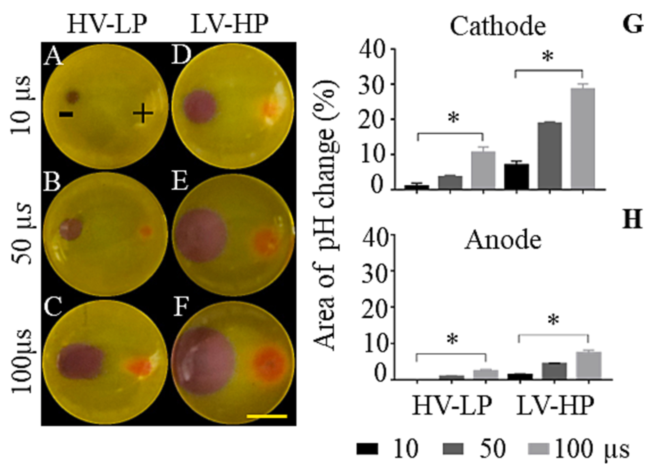
Evaluation of the effect of duration of pulses on pH change for LV-HP and HV-LP conditions in the vicinity of electrodes. A universal pH indicator was used to visualize and quantify pH change due to PEF for HV-LP (A-C) and HV-LP (D-F) groups by applying pulses with 10, 50 and 100 μs pulse widths. The cathode (−) and anode (+) locations are marked in the figure. The graph shows the corresponding area fraction (%) of pH change at the cathode (G) and anode (H) with respect to the total area of a single well in a 24-well plate. Scale bar, 5 mm; *p < 0.0332.
3.3. pH alterations has greater contribution than temperature change to ablation size during LV-HP and HV-LP IRE
IRE is known to cause temperature increases in the vicinity of the electrodes. Here, we sought to determine the contribution of pH and temperature changes towards cell death during LV-HP (1000 V/cm 900 pulses) and HV-LP (2000 V/cm 90 pulses) conditions. Simulation data for LV-HP showed moderate temperature changes in the vicinity of electrodes and negligible change in rest of the regions in the 3D tumor mimic, but HV-LP group showed significant changes in temperature throughout the well (Fig. 4E & 4F). We found that temperature changes within the in vitro 3D tumor mimic during LV-HP were lower (peak: 39 °C) when compared to HV-LP (peak: 47 °C) conditions, falling well under the thresholds and durations that result in cell death due to thermal damage (Fig. 7L & 7 M). The in vitro findings for LV-HP were also confirmed by in vivo measurements during ablation in swine liver, where the peak temperature adjacent to the electrodes did not exceed 42 °C, rapidly reverting to physiologic levels following cessation of pulse application (Fig. 3I). We then tested the impact of mitigating temperature changes in vitro on the ablation size by performing the experiment on an ice bath (4 °C), finding that it had no significant impact on the HV-LP (PEF only = 98%, PEF + temp control = 98%) condition but substantially reduced the size of LV-HP (PEF only = 99%, PEF + temp control = 66%) ablation. We then investigated the role of pH alterations in cell death. We found that the use of neutralizing buffer substantially reduced the size of the ablation for both the HV-LP and moderately for LV-HP conditions (52% and 62%, respectively). The greatest effect was observed when controlling both pH and temperature, where the ablation size for HV-LP and LV-HP reduced to 51% and 44% respectively (Fig. 7A – 7I). We recorded pre, intra- and post-pulse current drawn during these studies as proxy for IRE associated conductivity changes. For both LV-HP and HV-LP conditions, there was increased current flow when comparing pre- and post-pulse conditions (Fig. 7J & 7 K). Moreover, the current drawn was sensitive to pH and temperature control, demonstrating increased and reduced values respectively for each condition. Interestingly, the overall change in current flow or the underlying conductivity change was substantially lower for LV-HP condition when compared to conventional IRE with HV-LP.
Fig. 7.

Evaluation of the effect of pH and temperature towards cell death. PEFs delivered to ablate the tumor was assessed for temperature and pH changes in the 3D tumor mimic and its contribution towards cell death. HV-LP (A-D) and LV-HP (E-H) groups were controlled for pH and temperature both individually and simultaneously during IRE treatment and assessed for cell viability using PI (red, dead cells) and calcein-AM (green, live cells) dual stain. I. The graph quantifies the % area of the tumor mimic that underwent ablation. Electric current measurements were carried out for PEF, PEF + temperature and PEF + pH-controlled groups for the LV-HP (J) and HV-LP (K) treatment parameters. Electric current was measured after the 1st pulse (Pre-pulse), 88th and 898th pulse (Pulse) and 90th and 900th pulse (Post-pulse) for HV-LP and LV-HP groups respectively. Changes in gel temperature during the treatment were recorded using a fiber optic sensor - one positioned near the cathode and the other midway between the two electrodes for LV-HP (L) and HV-LP (M) groups. The cathode (−) and anode (+) locations are marked in the figure. Scale bar, 5 mm.
3.4. ATP depletion is an early event in cell death during LV-HP and HV-LP conditions
IRE is associated with the depletion or loss of intracellular ATP, which we compared between the HV-LP and LV-HP conditions. Total intra-cellular ATP was measured using a luciferase-based assay (Cell-Titer-Glo 3D) immediately after treatment following different numbers of pulse application (LV-HP: EFS – 1000 V/cm, pulse # – 90, 300, 600 and 900; HV-LP: EFS – 2000 V/cm, pulse # – 10, 45 and 90), corresponding to different duration and level of PEF treatment. The greatest reduction in intracellular ATP occurred following 90 and 10 pulses for LV-HP and HV-LP respectively (Fig. 8A & 8B), corresponding to early EP of cells. Thereon, there was a continued reduction in ATP levels in the 3D tumor mimic with the application of additional pulses. The residual ATP levels in the tumor mimic for similar sized ablations at 900 (LV-HP) and 90 (HV-LP) pulses were comparable. These differences persisted despite substantial differences in timescales between the two PEF treatment conditions.
Fig. 8.

Quantification of intracellular ATP immediately following IRE treatment. 1000 V/cm (LV-HP, A) and 2000 V/cm (HV-LP, B) groups were treated with various pulse numbers as shown in the graph and the intracellular ATP levels were estimated using 3-D CellTiter-Glo assay immediately following IRE. **p < 0.0021, *p < 0.0332.
3.5. LV-HP and HV-LP induce severe and early intracellular ROS generation
Exposure of cells to electric fields can produce intracellular reactive oxygen species (ROS). We studied the differences in ROS production during PEF treatment under LV-HP (EFS – 500 V/cm, pulse # – 90, 450 and 900) and HV-LP (EFS – 2000 V/cm, pulse # – 10, 45 and 90) conditions. We used CellROX green to investigate ROS levels during various timepoints during ablation. ROS production was evident following treatment with even a small number of pulses, where peak levels were observed at 450 and 90 pulses for the LV-HP and HV-LP conditions respectively (Fig. 9A – 9G). ROS levels at the end of pulse delivery for complete ablation were lower than that of peak levels during mid-duration of pulse delivery, but substantially higher than what was observed at start of pulse application. Residual ROS levels were more visible in the region around the anode but not the cathode for both treatment conditions.
Fig. 9.

Measurement of intra-cellular ROS generation due to IRE. The 3D tumor mimic was treated with IRE parameters: 500 V/cm – 90, 450 and 900 pulses (B-D) and 2000 V/cm – 10, 45, and 90 pulses (E-G) immediately followed by staining with CellROX Green (green, 10 μM) and Hoechst (blue, 0.3 μg/mL) for 1 h. The baseline level of ROS was identified using sham group (A). The cathode (−) and anode (+) locations are marked in the figure. Scale bar = 1 mm.
4. Discussion
In this study, we explored the contribution of mechanisms other than membrane permeabilization and thermal damage to cell death during PEF treatment by comparing two different pulse parameter sets in a 3D in vitro liver tumor model. A candidate LV-HP parameter set was identified to produce an ablation size comparable to that of conventional IRE with HV-LP parameters. The equivalency of LV-HP to conventional IRE was verified in vivo by performing image-guided ablations in swine liver. We hypothesized that cell death with the two treatment conditions would occur through divergent pathways. For both conventional HV-LP and our test LV-HP pulse conditions, increased ROS activity, pH change and ATP loss was observed. These changes may be secondary to electroporation, reversible or IRE, but are injury mechanisms that may also contribute to cell death. We found that under the LV-HP condition, conventional membrane permeabilization related responses were muted (e.g., relatively small change in current drawn). Simultaneously, this treatment paradigm was more sensitive to combined pH and temperature control. This suggests that insults other than membrane permeabilization may have important contributions to the ablative effect during LV-HP treatment. We found that tissue cell death from pH alterations to be dependent on the total duration of exposure to PEF, as a function of pulse width and total number of pulses, but not the EFS. Thus, total charge delivered was the major determinant of LV-HP ablations, where charge passage within tissue correlated with pH change and increased ROS activity. Interestingly, ATP loss appeared to be independent of treatment duration, charge delivered or other parameters, being correlated only to the ablation volume. This phenomenon suggests a connection between PEF treatment, ATP loss and cell death [38]. The limited contribution of thermal damage during LV-HP ablation was confirmed by temperature measurements, and by neutralization of this effect using ice baths. Cumulatively, our results demonstrate that ablation with parameters conventionally used for non-thermal IRE may involve sizeable contributions from other injury mechanisms, and that LV-HP parameters can produce clinically meaningful ablation volumes.
The clinical utility of IRE is predicated on being able to perform ablation while limiting thermal injury at the site of treatment. Thermal damage to tissues results in the denaturing of proteins and damaging or altering the extra-cellular matrix composition [39]. Clinically, the usage of IRE requires the application of very high voltage (2000–3000 V) between the electrodes, drawing very high current into the system resulting in joule heating of the tissue. Optimization of pulse parameters has allowed reduction of this form injury, yet it is infeasible to completely eliminate thermal damage or temperature changes during IRE. Several studies have noted that such effects are restricted to the immediate vicinity of the electrodes [40,41]. EFS contributes to both the volume of IRE ablation and thermal damage, with the latter increasing in size whenever larger ablations are attempted [42]. Thermal damage at a given EFS can be mitigated by pulse duration and frequency optimization, allowing time for heat dissipation without impacting IRE efficacy. The clinically used pulse parameters of 70–100 μs pulse width and ~ 0.5 Hz frequency are designed to meet this need, but further changes are not possible as experimental studies have shown a negative impact on electroporation efficacy. These factors may explain the feasibility of performing sizeable ablations using LV-HP parameters without encountering considerable thermal damage. During IRE with LV-HP parameters, the EFS is kept low (500–1000 V/cm) while the ablation volume was driven by the total duration of treatment. This paradigm allows the use of previously optimized pulse width and frequency parameters to ensure heat dissipation while at the same time not relying solely on EFS for maximizing ablation size.
The inverse relationship between EFS and PEF treatment duration is well established, and is bounded by a minimum number of pulses (typically 20–50) that are required to induce IRE. The upper bound of the relationship has been examined through in vitro and in vivo studies, where treatment duration exhibited a non-linear relationship with ablation volume for a fixed EFS. Pucihar et al. showed that a similar electroporation outcome can be obtained either by changing the EFS or total pulse duration where a decrease in one is compensated by an increase in the other while delivering the same amount of energy [20]. It is widely acknowledged that increasing pulse application beyond 100 pulses elicits minimal increase in ablation volume or cell killing efficacy. It is to be noted that these studies were performed at EFS values of 1000 V/cm or higher. Experiments performed at lower EFS values were deemed to have poor efficacy as at the tested treatment durations, typically fewer than 100 pulses, where the cytotoxic effect was muted. These prior experiments testing HV-LP parameters worked under the assumption that treatment efficacy was linked to IRE or thermal damage. In our work we deliberately explored the LV-HP parameter space where we unearthed a EFS – treatment duration relationship where a 50% reduction in the former could be compensated by approximately 7–10 fold increase in the duration of exposure, in the form of increased pulse delivery. Using this approach, we were able to show meaningful ablation sizes even at EFS levels as low as 500 V/cm. Even though a reduction in EFS can be compensated by increase in pulses, a minimum threshold EFS needs to be attained to at least reversibly electroporate the cells to induce membrane damage which can be determined using simulation models. Rajagopalan et al. showed that HUVEC cells did not get electroporated at 250 V/cm 600 pulses while maintaining cell viability but with altered actin cytoskeleton and tight junction protein [43].
Existing simulation models estimate cell death based on the EFS and thermal damage, where these effects models have limited utility at EFS of 1000 V/cm or lesser. The ablation zone from in vitro 3D tumor mimics testing HV-LP pulse parameters agrees with the predicted computational data, as estimated by IRE threshold isoline (700 V/cm). Interestingly, the observed ablation zone for LV-HP condition was much greater than the predicted EFS values typically used for conventional IRE. Our experimental setup did not delineate the region of reversible electroporation, but it is possible that the sizeable ablation observed may arise from the diffusion of harmful cytotoxic electrolytic by-products to the well periphery and eventually crossing the cell membrane of reversibly permeabilized cells leading to cell death. The temperature contour plots show localized heating near the electrodes for LV-HP group, unlike HV-LP where intense heating is observed between the two electrodes and covering close to 50 % of the well area. The effect of electrolysis, pH change, and ROS on cell death are not incorporated into existing simulation models, a potential reason for the observed discrepancy between experimental and computational data. Considering the manifestation of these non-IRE forms of injury even under HV-LP conditions, it may become necessary to incorporate these other biological effects into computational models in the literature.
PEF parameters used for IRE are well known to cause electrolytic and hydrolytic reactions. PEF delivery causes the degradation of electrodes due to the reduction of metals into ions at the anode, and oxidation of Cl− ions to Cl2 gas occurs at the cathode [23,44]. PEF also results in the production of hydrogen peroxide where hydrogen is oxidized to H+ ions at the anode and it is reduced to hydrogen peroxide at the cathode. Prolonged exposure to electric field further reduces H2O2 to water as evident from ROS levels at higher pulse numbers in both LV-HP and HV-LP groups [45]. PEF related electrolysis can be mitigated by several techniques such as the use of biphasic waveforms, alternating electrode polarity or by modifying electrode properties. Wandel et al. used a bipolar electrode to increase the ablation zone by increasing the voltage (2700–3000 V), pulse width (70–100 μs) or number of cycles applied in combination with hypotonic fluid infusion or electrode perfusion [46]. Electrolytic effects, along with associated pH alterations were observed in both HV-LP and LV-HP conditions, where the region of change increased proportionally to the total charge delivered to the 3D tumor mimic. These pH changes are not dependent on EFS and the amount of acidic and basic compounds generated at respective electrodes were dependent on the amount of charge delivered to the well. The pH change was more pronounced in the LV-HP group as evident from the data presented and was identified to be a substantial contributor to cell death. It is possible that the large volumes of cell death in LV-HP was from passive diffusion of the electrolytic products to the periphery of the tumor mimic where the cells are reversibly electroporated facilitating the uptake of these cytotoxic compounds. Rubinsky et al. have previously shown that the pH increases significantly after the application of PEF in cuvettes using liver and prostate cancer cells [47]. Philips et al. performed tissue ablations using PEF by combining EP with electrolysis. They found that the type of lesion in the PEF-electrolysis group was similar to the electrolysis group confirming that PEF treatment related electrolysis is cytotoxic and capable of producing ablations [27,48–51]. Yangpeng et al. demonstrated that the use of short high voltage (SHV) pulses in conjugation with long low voltage (LLV) pulses substantially increased the ablation zone in potato model instead of using large number of SHV pulses which is currently used in the clinic. In addition, they showed that the area of pH change increased with increase in pulses for LLV conditions whereas SHV group showed very minimal change, similar to our results [52].
PEF delivery into tissue also causes electrochemical reactions that can increase the levels of ROS within cells, where concomitant pore formation in the membrane can increase the transport of extracellular ROS into cells, leading to oxidative stress. PEF treatment is known to produce highly reactive peroxide, hydroxyl and free oxygen species that can cause lipid peroxidation, along with protein and DNA damage. Hypothetically PEF application may also interfere with normal biological processes that mitigate ROS within cells, increasing its levels and damaging potential. Especially in regions where cells are reversibly electroporated, the diffusion of ROS across the compromised cell membrane damages the DNA and other cellular components leading to oxidative stress and eventually cell death. Extracellular pH alterations are known to trigger MAPK signaling, resulting in intracellular ROS production as well, and can cause DNA damage that leads to cell death [53]. We observed high levels of intracellular ROS in both treatment groups, demonstrating varying kinetics in terms of peak levels. In LV-HP condition, there was limited ROS when 10% of the pulses were delivered where maximum levels were observed at 50% mark. In contrast, HV-LP samples showed high ROS signals even when just 10% of the pulses were delivered. In this group peak levels were detected when 50% of the pulses were delivered, then reducing to lower levels at the time of treatment completion. Remarkably, LV-HP treatment group demonstrated similar kinetics. Overall ROS levels were greater in the LV-HP samples when compared to HV-LP. The levels of ROS seemed to map regions having viable cells or those within the regions where cell death would be detected at 24 h. Regions of complete cell death had reduced ROS levels, indicating the presence of an underlying biological process in its production. Similar observations have been previously reported in literature. Ruzgys et al. showed that the production of ROS and its impact on electroporation efficiency is dependent on the type of metal ions generated from the electrodes [54]. In another study, Yang et al. used numerical models to predict the production and diffusion of hydrogen peroxide, a key species in the induction of oxidative stress in cells by the treatment of high EFS plasma [55].
EP or IRE of a cell is associated with rapid depletion of intracellular ATP. The change in ATP levels is partially related to leakage, but the majority is consumed for maintenance of cell viability and recovery of homeostasis. A significant reduction in intracellular ATP was observed within delivery of 10% of pulses in HV-LP and LV-HP conditions even though the EFS and gradient distribution had a 2-fold difference. The reason for this effect is unclear as we know that the majority of tumor mimic volume in LV-HP remains viable at this level of treatment duration. The ATP levels then continuously reduced as pulse delivery progressed. Final ATP levels roughly correlated with the total volume of the tumor mimic that had cell death at 24 h. As we did not perform blocking conditions for IRE, it is unclear whether this change in ATP levels was due to EP related losses or other processes. Cells undergoing depolarization or hyperpolarization by an external electric field consume ATP during recovery of the transmembrane voltage. This may be a possible mechanism to explain large ATP loss seen in LV-HP condition. Calcium EP performed on colorectal cancer cell line and primary dermal fibroblasts resulted in drastic mitochondrial membrane depolarization and significant ATP loss within 5 min of treatment [56]. Similarly, Lew et al. have shown that chlorpromazine induced membrane potential depolarization results in marked loss of ATP in soybean roots [57]. Intracellular ATP levels are also an important determinant of the model of cell death (apoptosis or necrosis) as ATP is an important substrate for caspase mediated cell death during apoptosis but is not involved in necrosis. Previous data from Razakamanantsoa et al. shows that ATP loss results in a caspase independent necrotic cell death in a murine bladder cancer cell line [38]. A dose dependent depletion of ATP was observed during PEF treatment of human cancer lines by Hansen et al, where PEF treatment in the presence of extracellular calcium decreased the required EFS to achieve the same treatment outcome in terms of cell viability [58]. It is unclear whether similar mechanisms contribute to effects seen during LV-HP PEF treatment.
Our study validates several of previous findings in the literature while contributing new evidence on non-IRE injury mechanisms that can produce cell death at lower voltages. Although we identified various factors that contribute to cell death besides IRE, our study has some limitations. Our in vivo experiments showed the feasibility of reduction in voltage to achieve a similar ablation outcome to that of conventional IRE by increasing the pulse duration. Our current results are relevant for EFS in the range of 500–1000 V/cm, but the lower bound for LV-HP treatment is yet to be established. However, the subsequent experiments were performed using a 3-D in vitro tumor model. 3-D collagen gels have uniform tissue properties as opposed to actual tissue. Native tissue electrical properties vary depending on the density of surrounding vasculature, tumor mass, etc. The percentage contribution of each of these mechanisms towards tissue ablation has not been explored here. The study was performed only with a single human liver cancer cell line (Huh7), where testing with additional cancer cells would be required to confirm the broad applicability of our findings. N-acetyl cysteine (NAC) is an antioxidant that can neutralize intracellular ROS and can be used as a blocking condition to identify the specific contribution of oxidative damage to cell death during LV-HP treatment. There can be other mechanisms like the bystander effect that can contribute to cell death, which were not studied in our experiments [59]. Cells contain various enzymes (nucleases and proteases) that when released due to sudden cell death can affect adjacent cells and ECM proteins. There are also fundamental challenges in blocking electroporation while applying electric pulses, thus we are unable to fully isolate the effect of reversible or irreversible membrane permeabilization on cell death. Existing simulation models cannot predict ablation region accurately for LV-HP conditions and requires further development. We hope to address some of these limitations in our future studies.
5. Conclusion
Our results show that LV-HP PEF treatment can produce ablation volumes that are comparable to conventional IRE using HV-LP PEF parameters, with minimal thermal damage. A two-fold decrease in EFS can be compensated by approximately ten-fold increase in treatment duration. We also determined that besides membrane permeabilization and heat, factors such as pH alteration, ROS, and intracellular ATP loss are major contributors to cell death during PEF treatment. The severity of injury from the latter mechanisms seems to be driven by total charge or current delivered into the tissue, unlike HV-LP IRE where EFS is the key factor. We note that pH change had a greater impact on the ablation size than temperature change in both LV-HP and HV-LP conditions. Current computational models do not predict ablation volume accurately in LV-HP conditions due to lack of consideration of these electrolytic effects. Better understanding of these secondary mechanisms can help us design treatment parameters at lower voltages while avoiding the undesired effects of PEF such as thermal damage and electrical arcing.
Acknowledgements
Confocal images were imaged in the Light Microscopy Facility and Nikon Center of Excellence at the Institute for Applied Life Sciences, University of Massachusetts Amherst with support from the Massachusetts Life Science Center. The 3-D printed parts for electrode inserts were printed using Advanced Digital Design and Fabrication core facility, University of Massachusetts Amherst.
Funding support
G.S. acknowledges grant and funding support from the National Cancer Institute and the National Institute of Diabetes, and Digestive and Kidney Diseases of the National Institutes of Health under Award Number U54CA137788/U54CA132378, R01CA236615 and R01DK129990, the Dept. of Defense CDMRP PRCRP Award CA170630 and CA190888, and the Institute for Applied Life Sciences in the University of Massachusetts at Amherst.
Declaration of Competing Interest
The authors declare the following financial interests/personal relationships which may be considered as potential competing interests: Govindarajan Srimathveeravalli reports financial support was provided by National Institutes of Health. Govindarajan Srimathveeravalli reports financial support was provided by Congressionally Directed Medical Research Program. Govindarajan Srimathveeravalli reports a relationship with Aperture Medical that includes: equity or stocks.
Footnotes
Disclosures
G. S. has stock options in Aperture medical and is a board member of the Society for Interventional Radiology Foundation. The other authors report no relevant disclosures related to the work presented here.
CRediT authorship contribution statement
Neeraj Raghuraman Rajagopalan: Data curation, Formal analysis, Investigation, Methodology, Validation, Visualization, Writing. Tarek Munawar: Data curation, Formal analysis, Investigation, Methodology, Validation, Writing. Masashi Fujimori: Formal analysis, Investigation, Methodology, Validation. William-Ray Vista: Data curation, Formal analysis, Investigation, Methodology, Validation. Thomas Wimmer: Investigation, Methodology, Validation. Narendra Babu Gutta: Investigation, Methodology, Validation. Stephen B. Solomon: Funding acquisition, Resources, Supervision, Writing. Govindarajan Srimathveeravalli: Conceptualization, Data curation, Funding acquisition, Project administration, Resources, Visualization, Supervision, Writing.
Data availability
Data will be made available on request.
References
- [1].Rubinsky B, Onik G, Mikus P, Irreversible electroporation: A new ablation modality - Clinical implications, Technol. Cancer Res. Treat 6 (1) (2007) 37–48. [DOI] [PubMed] [Google Scholar]
- [2].Granot Y, Ivorra A, Maor E, Rubinsky B, In vivo imaging of irreversible electroporation by means of electrical impedance tomography, Phys. Med. Biol 54 (16) (2009) 4927–4943. [DOI] [PubMed] [Google Scholar]
- [3].Murray KS, et al. , Pilot Study to Assess Safety and Clinical Outcomes of Irreversible Electroporation for Partial Gland Ablation in Men with Prostate Cancer, J. Urol 196 (3) (2016) 883–890. [DOI] [PMC free article] [PubMed] [Google Scholar]
- [4].Hsiao CY, Huang KW, Irreversible Electroporation: A Novel Ultrasound-guided Modality for Non-thermal Tumor Ablation, J. Med. Ultrasound 25 (4) (2017) 195–200. [DOI] [PMC free article] [PubMed] [Google Scholar]
- [5].Silk MT, et al. , Percutaneous ablation of peribiliary tumors with irreversible electroporation, J. Vasc. Interv. Radiol 25 (1) (2014) 112–118. [DOI] [PubMed] [Google Scholar]
- [6].Ueshima E, et al. , Transmural ablation of the normal porcine common bile duct with catheter-directed irreversible electroporation is feasible and does not affect duct patency, Gastrointest. Endosc 87 (1) (2018) 300.e1–300.e6. [DOI] [PMC free article] [PubMed] [Google Scholar]
- [7].Kodama H, et al. , Catheter-based endobronchial electroporation is feasible for the focal treatment of peribronchial tumors, J. Thorac. Cardiovasc. Surg 155 (5) (2018) 2150–2159.e3. [DOI] [PMC free article] [PubMed] [Google Scholar]
- [8].Maor E, Ivorra A, Leor J, Rubinsky B, The effect of irreversible electroporation on blood vessels, Technol. Cancer Res. Treat 6 (4) (2007) 307–312. [DOI] [PubMed] [Google Scholar]
- [9].Maor E, Ivorra A, Rubinsky B, Non thermal irreversible electroporation: Novel technology for vascular smooth muscle cells ablation, PLoS One 4 (3) (2009) pp. [DOI] [PMC free article] [PubMed] [Google Scholar]
- [10].Maor E, Ivorra A, Mitchell JJ, Rubinsky B, Vascular smooth muscle cells ablation with endovascular nonthermal irreversible electroporation, J. Vasc. Interv. Radiol 21 (11) (2010) 1708–1715. [DOI] [PMC free article] [PubMed] [Google Scholar]
- [11].Tsong TY, Electroporation of cell membranes, Biophys. J 60 (August) (1991, 1991,) 297–306. [DOI] [PMC free article] [PubMed] [Google Scholar]
- [12].Teissié J, Eynard N, Gabriel B, Rols MP, Electropermeabilization of cell membranes, Adv. Drug Deliv. Rev 35 (1) (1999) 3–19. [DOI] [PubMed] [Google Scholar]
- [13].Hogenes AM, et al. , The Influence of Irreversible Electroporation Parameters on the Size of the Ablation Zone and Thermal Effects: A Systematic Review, Technol. Cancer Res. Treat 22 (766) (2023) pp. [DOI] [PMC free article] [PubMed] [Google Scholar]
- [14].Bilska AO, Debruin KA, Krassowska W, Theoretical modeling of the effects of shock duration, frequency, and strength on the degree of electroporation, Bioelectrochem. Bioenerg 51 (2) (2000) 133–143. [DOI] [PubMed] [Google Scholar]
- [15].Davalos RV, Rubinsky B, Temperature considerations during irreversible electroporation, Int. J. Heat Mass Transf 51 (23–24) (2008) 5617–5622. [Google Scholar]
- [16].Faroja M, et al. , Irreversible electroporation ablation: Is all the damage nonthermal? Radiology 266 (2) (2013) 462–470. [DOI] [PubMed] [Google Scholar]
- [17].Golberg A, et al. , Preventing Scars after Injury with Partial Irreversible Electroporation, J, Invest. Dermatol 136 (11) (2016) 2297–2304. [DOI] [PMC free article] [PubMed] [Google Scholar]
- [18].Kotnik T, Rems L, Tarek M, Miklavčič D, Membrane Electroporation and Electropermeabilization: Mechanisms and Models, Annu. Rev. Biophys 48 (1) (2019) 63–91. [DOI] [PubMed] [Google Scholar]
- [19].Weaver JC, Smith KC, Esser AT, Son RS, Gowrishankar TR, A brief overview of electroporation pulse strength-duration space: A region where additional intracellular effects are expected, Bioelectrochemistry 87 (2012) 236–243. [DOI] [PMC free article] [PubMed] [Google Scholar]
- [20].Pucihar G, Krmelj J, Reberšek M, Napotnik TB, Miklavčič D, Equivalent pulse parameters for electroporation, IEEE Trans. Biomed. Eng 58 (11) (2011) 3279–3288. [DOI] [PubMed] [Google Scholar]
- [21].Shafiee H, Garcia PA, Davalos RV, A preliminary study to delineate irreversible electroporation from thermal damage using the arrhenius equation, J. Biomech. Eng 131 (7) (2009) 1–5. [DOI] [PubMed] [Google Scholar]
- [22].Garcia PA, Rossmeisl JH, Neal RE, Ellis TL, Davalos RV, A parametric study delineating irreversible electroporation from thermal damage based on a minimally invasive intracranial procedure, Biomed. Eng. Online 10 (April) (2011). [DOI] [PMC free article] [PubMed] [Google Scholar]
- [23].Ben-David E, Appelbaum L, Sosna J, Nissenbaum I, Goldberg SN, Characterization of irreversible electroporation ablation in in vivo, porcine liver, Am. J. Roentgenol 198 (1) (2012) pp. [DOI] [PubMed] [Google Scholar]
- [24].Appelbaum L, Ben-David E, Sosna J, Nissenbaum Y, Goldberg SN, US findings after irreversible electroporation ablation: Radiologic-pathologic correlation, Radiology 262 (1) (2012) 117–125. [DOI] [PubMed] [Google Scholar]
- [25].Ben-David E, et al. , Irreversible electroporation: Treatment effect is susceptible to local environment and tissue properties, Radiology 269 (3) (2013) 738–747. [DOI] [PMC free article] [PubMed] [Google Scholar]
- [26].Appelbaum L, Ben-David E, Faroja M, Nissenbaum Y, Sosna J, Goldberg SN, Irreversible electroporation ablation: Creation of large-volume ablation zones in in vivo porcine liver with four-electrode arrays, Radiology 270 (2) (2014) 416–424. [DOI] [PubMed] [Google Scholar]
- [27].Phillips M, Rubinsky L, Meir A, Raju N, Rubinsky B, Combining electrolysis and electroporation for tissue ablation, Technol. Cancer Res. Treat 14 (4) (2015) 395–410. [DOI] [PubMed] [Google Scholar]
- [28].Mattera R, et al. , Effects of polyphenols on oxidative stress-mediated injury in cardiomyocytes, Nutrients 9 (5) (2017) 1–43. [DOI] [PMC free article] [PubMed] [Google Scholar]
- [29].Perkons NR, et al. , Electrolytic ablation enables cancer cell targeting through pH modulation, Commun. Biol 1 (1) (2018) 1–10. [DOI] [PMC free article] [PubMed] [Google Scholar]
- [30].COMSOL I, “COMSOL Multiphysics 6.0,” 2023. [Online]. Available: https://www.comsol.com/.
- [31].Stancl J, Skocilas J, Landfeld A, Zitny R, Houska M, Electrical and thermodynamic properties of a collagen solution, Acta Polytech. 57 (3) (2017) 229–234. [Google Scholar]
- [32].Davalos RV, Mir LM, Rubinsky B, Tissue ablation with irreversible electroporation, Ann. Biomed. Eng 33 (2) (2005) 223–231. [DOI] [PubMed] [Google Scholar]
- [33].Miklavčič D, Šemrov D, Mekid H, Mir LM, A validated model of in vivo electric field distribution in tissues for electrochemotherapy and for DNA electrotransfer for gene therapy, Biochim. Biophys. Acta - Gen. Subj 1523 (1) (2000) 73–83. [DOI] [PubMed] [Google Scholar]
- [34].Edd JF, Davalos RV, Mathematical modeling of irreversible electroporation for treatment planning, Technol. Cancer Res. Treat 6 (4) (2007) 275–286. [DOI] [PubMed] [Google Scholar]
- [35].Garcia PA, et al. , Intracranial nonthermal irreversible electroporation: In vivo analysis, J. Membr. Biol 236 (1) (2010) 127–136. [DOI] [PubMed] [Google Scholar]
- [36].Chang IA, Nguyen UD, Thermal modeling of lesion growth with radiofrequency ablation devices, Biomed. Eng. Online 3 (2004) 1–19. [DOI] [PMC free article] [PubMed] [Google Scholar]
- [37].Šel D, Cukjati D, Batiuskaite D, Slivnik T, Mir LM, Miklavčič D, Sequential finite element model of tissue electropermeabilization, IEEE Trans. Biomed. Eng 52 (5) (2005) 816–827. [DOI] [PubMed] [Google Scholar]
- [38].Razakamanantsoa L, et al. , Acute ATP loss during irreversible electroporation mediates caspase independent cell death, Bioelectrochemistry vol. 150, no. September 2022, p. 108355, 2023. [DOI] [PMC free article] [PubMed] [Google Scholar]
- [39].Županič A, Miklavčič D, Tissue heating during tumor ablation with irreversible electroporation, Elektroteh. Vestnik/Electrotechnical Rev 78 (1–2) (2011) 42–47. [Google Scholar]
- [40].Van Den Bos W, et al. , Thermal Energy during Irreversible Electroporation and the Influence of Different Ablation Parameters, J. Vasc. Interv. Radiol 27 (3) (2016) 433–443. [DOI] [PubMed] [Google Scholar]
- [41].Agnass P, et al. , Mathematical modeling of the thermal effects of irreversible electroporation for in vitro, in vivo, and clinical use: a systematic review, Int. J. Hyperth 37 (1) (2020) 486–505. [DOI] [PubMed] [Google Scholar]
- [42].Davalos RV, Bhonsle S, Neal RE, Implications and considerations of thermal effects when applying irreversible electroporation tissue ablation therapy, Prostate 75 (10) (2015) 1114–1118. [DOI] [PMC free article] [PubMed] [Google Scholar]
- [43].Rajagopalan NR, et al. , “Cytoskeletal Remodeling and Gap Junction Translocation Mediates Blood–Brain Barrier Disruption by Non-invasive Low-Voltage Pulsed Electric Fields, Ann. Biomed. Eng, no. 0123456789, 2023. [DOI] [PubMed] [Google Scholar]
- [44].Guenther E, Klein N, Mikus P, Stehling MK, Rubinsky B, Electrical breakdown in tissue electroporation, Biochem. Biophys. Res. Commun 467 (4) (2015) 736–741. [DOI] [PubMed] [Google Scholar]
- [45].Drogui P, Elmaleh S, Rumeau M, Bernard C, Rambaud A, Hydrogen peroxide production by water electrolysis: Application to disinfection, J. Appl. Electrochem 31 (8) (2001) 877–882. [Google Scholar]
- [46].Wandel A, et al. , Optimizing Irreversible Electroporation Ablation with a Bipolar Electrode, J. Vasc. Interv. Radiol 27 (9) (2016) 1441–1450.e2. [DOI] [PubMed] [Google Scholar]
- [47].Rubinsky L, Guenther E, Mikus P, Stehling M, and Rubinsky B, “Electrolytic Effects During Tissue Ablation by Electroporation,” Technol. Cancer Res. Treat, vol. 15, no. 5, pp. NP95–NP103, 2016. [DOI] [PubMed] [Google Scholar]
- [48].Phillips M, Raju N, Rubinsky L, Rubinsky B, Modulating electrolytic tissue ablation with reversible electroporation pulses, Technology 03 (01) (2015) 45–53. [Google Scholar]
- [49].Lv Y, Zhang Y, Rubinsky B, Molecular and histological study on the effects of electrolytic electroporation on the liver, Bioelectrochemistry 125 (2019) 79–89. [DOI] [PubMed] [Google Scholar]
- [50].Stehling MK, Guenther E, Mikus P, Klein N, Rubinsky L, Rubinsky B, Synergistic combination of electrolysis and electroporation for tissue ablation, PLoS One 11 (2) (2016) 1–23. [DOI] [PMC free article] [PubMed] [Google Scholar]
- [51].Phillips M, Krishnan H, Raju N, Rubinsky B, Tissue Ablation by a Synergistic Combination of Electroporation and Electrolysis Delivered by a Single Pulse, Ann. Biomed. Eng 44 (10) (2016) 3144–3154. [DOI] [PubMed] [Google Scholar]
- [52].Lv Y, Yao C, Rubinsky B, A Conceivable Mechanism Responsible for the Synergy of High and Low Voltage Irreversible Electroporation Pulses, Ann. Biomed. Eng 47 (7) (2019) 1552–1563. [DOI] [PubMed] [Google Scholar]
- [53].Riemann A et al. , “Acidic environment leads to ROS-Induced MAPK signaling in cancer cells,” PLoS One, vol. 6, no. 7, 2011. [DOI] [PMC free article] [PubMed] [Google Scholar]
- [54].Ruzgys P, Novickij V, Novickij J, Šatkauskas S, Influence of the electrode material on ROS generation and electroporation efficiency in low and high frequency nanosecond pulse range, Bioelectrochemistry 127 (2019) 87–93. [DOI] [PubMed] [Google Scholar]
- [55].Yang Z and Liu D, “Enhanced transmembrane transport of reactive oxygen species by electroporation effect of plasma,” Plasma Process. Polym, vol. 18, no. 11, 2021. [Google Scholar]
- [56].Gibot L, Montigny A, Baaziz H, Fourquaux I, Audebert M, and Rols MP, “Calcium delivery by electroporation induces in vitro cell death through mitochondrial dysfunction without DNA damages,” Cancers (Basel)., vol. 12, no. 2, 2020. [DOI] [PMC free article] [PubMed] [Google Scholar]
- [57].Lew RR, Spanswick RM, CHLORPROMAZINE INDUCES MEMBRANE POTENTIAL DEPOLARIZATION AND ATP LOSS, AND INHIBITS MICROSOMAL ATPase IN SOYBEAN (GL YCINE MAX L.) ROOTS, Biochim. Biophys. Acta 731 (1983) 421–427. [Google Scholar]
- [58].Hansen EL, Sozer EB, Romeo S, Frandsen SK, Vernier PT, Gehl J, Dose-Dependent ATP depletion and cancer cell death following calcium electroporation, relative effect of calcium concentration and electric field strength, PLoS One 10 (4) (2015) 1–12. [DOI] [PMC free article] [PubMed] [Google Scholar]
- [59].Ruzgys P, Barauskaitė N, Novickij V, Novickij J, Šatkauskas S, The evidence of the bystander effect after bleomycin electrotransfer and irreversible electroporation, Molecules 26 (19) (2021) 1–11. [DOI] [PMC free article] [PubMed] [Google Scholar]
Associated Data
This section collects any data citations, data availability statements, or supplementary materials included in this article.
Data Availability Statement
Data will be made available on request.