Abstract
In digital breast tomosynthesis (DBT), the reconstruction is calculated from x-ray projection images acquired over a small range of angles. One step in the reconstruction process is to identify the pixels that fall outside the shadow of the breast, to segment the breast from the background (air). In each projection, rays are back-projected from these pixels to the focal spot. All voxels along these rays are identified as air. By combining these results over all projections, a breast outline can be determined for the reconstruction. This paper quantifies the accuracy of this breast segmentation strategy in DBT. In this study, a physical phantom modeling a breast under compression was analyzed with a prototype next-generation tomosynthesis (NGT) system described in previous work. Multiple wires were wrapped around the phantom. Since the wires are thin and high contrast, their exact location can be determined from the reconstruction. Breast parenchyma was portrayed outside the outline defined by the wires. Specifically, the size of the phantom was overestimated along the posteroanterior (PA) direction; i.e., perpendicular to the plane of conventional source motion. To analyze how the acquisition geometry affects the accuracy of the breast outline segmentation, a computational phantom was also simulated. The simulation identified two ways to improve the segmentation accuracy; either by increasing the angular range of source motion laterally or by increasing the range in the PA direction. The latter approach is a unique feature of the NGT design; the advantage of this approach was validated with our prototype system.
Keywords: Tomosynthesis, Mammography, X-Ray Imaging, Anthropomorphic Phantom, Image Reconstruction, Image Segmentation, Mathematical Modeling, Image Quality
1. INTRODUCTION
Many medical centers use the latest digital breast tomosynthesis (DBT) or “3D mammography” systems for breast cancer screening exams. In commercial DBT systems, multiple projection images are acquired as the x-ray tube rotates in a circular arc. Studies have shown that the optimal angular range for DBT is dependent on the imaging task. The advantage of a narrow angular range is seen in calcification imaging; Chan et al. demonstrated that there is greater sensitivity and conspicuity in the detection of calcifications.1 By contrast, the advantage of a wide angular range is in improving the -resolution (perpendicular to the breast support) which can benefit masses.2,3
In current DBT systems, the x-ray tube moves in one direction (laterally). We have built a prototype next-generation tomosynthesis (NGT) system with an additional component of tube motion along the posteroanterior (PA) direction. Our previous work showed that this design offers better visualization of low-frequency objects, such as a Defrise phantom.4-6 Specifically, blurring artifacts are eliminated in the PA direction and there is higher modulation contrast. Since this phantom is a surrogate for simulating large structures in the breast, our results suggest that the NGT design offers better visualization of masses and dense, glandular tissue.
Due to the nature of tomosynthesis, there are out-of-focus artifacts throughout the image, and it is difficult to localize structures correctly. This paper studies inherent limitations in the localization of the breast outline, and investigates how the accuracy of the breast outline is impacted by parameters in the acquisition geometry. Previous work by Kuo et al. described a method for calculating the breast outline in DBT.7 Each pixel outside the shadow of the breast is identified, and a ray is back-projected to the source. All voxels along the ray are treated as air in the reconstruction. This information is combined over multiple projections.
In this study, we simulate the breast outline using a computational phantom developed by Rodríguez-Ruiz et al.8 The phantom was derived from human subjects using structured light to image the breast outline under compression. Different ranges of tube motion in the lateral and PA directions are simulated. We analyze how the range of motion needs to be optimized to improve the accuracy of the breast outline. The NGT prototype system is used to validate the advantages of PA source motion with a physical phantom.
2. METHODS
2.1. Computational Phantom
The breast outline is simulated using a computational 3D phantom with 1.0 mm3 voxels. We model the average breast with advanced 3D curvature, as defined by Rodríguez-Ruiz et al.8 The chest wall-to-nipple distance is 9.7 cm, and the thickness is 54.0 mm. For the purpose of this paper, four slices at the superior surface of the phantom were truncated, since these slices are not representative of a breast shape under compression.
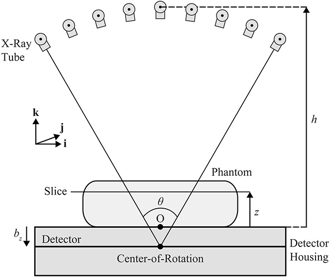
The reconstruction is first calculated in the conventional acquisition geometry (Figure 1), in which the focal spot (FS) rotates in a circular arc in the plane of the chest wall (i.e., the plane). The origin (O) is the midpoint of the chest wall side of the breast support; it is positioned at a distance relative to the center-of-rotation. The FS equations for this geometry are:
| (1) |
| (2) |
| (3) |
where and . In addition, denotes the total number of projections (17), and is the projection number (ranging from 1 to ). The central projection corresponds to the number . Finally, denotes the angular range of the scan. We model the AXS-2430 detector (Analogic Canada Corporation, Montreal, Quebec) with 0.085 mm detector elements.
Figure 1.
The x-ray tube rotates in the plane during the acquisition of the projections. The detector remains stationary during the scan. Slices in the phantom are reconstructed at the height relative to the breast support.
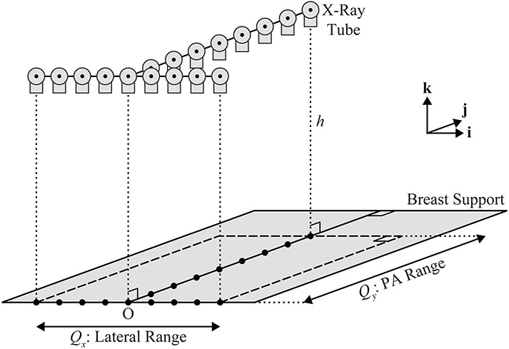
Second, the NGT design is simulated. This system is capable of source motion in the PA direction (), unlike a conventional system. An example of a motion supported by this system is T-shaped (Figure 2). The projections are acquired in the direction over the extent and in the direction over the extent .
Figure 2.
This diagram provides a 3D illustration of a T-shaped x-ray tube trajectory. In this example, there are nine source positions in the plane of the chest wall (left-to-right), and eight additional source positions along the mid-line perpendicular to the chest wall.
| (4) |
| (5) |
Unlike the conventional design, the -coordinate of the focal spot is fixed (). Since the two line segments that form the “T” have an intersection point, it follows that , where is the number of projections in the direction and is the number of projections in the direction. In this example, .
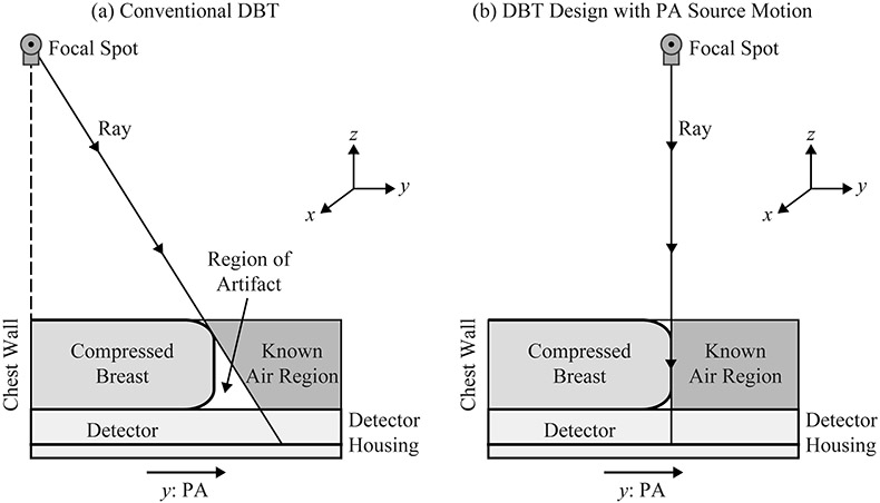
The reconstruction of the breast outline is calculated using the method depicted in Figure 3. First, we determine which pixels fall outside the shadow of the breast. The breast outline is then calculated by back-projecting rays from these pixels to the focal spot. In a clinical system, there is no x-ray tube motion along the PA direction, and hence the size of the phantom along this direction is overestimated [Figure 3(a)]. This research analyzes whether the size can be determined more precisely with source motion along the PA direction [Figure 3(b)].
Figure 3.
(a) In the conventional acquisition geometry, the breast volume is overestimated due to geometric magnification. (b) The use of PA source motion yields a more accurate calculation of the breast outline.
2.2. Physical Phantom
To investigate the accuracy of the breast outline segmentation in DBT, we analyzed images of the Mammo II phantom (Radiology Support Devices, Inc., Long Beach, CA). This is an anthropomorphic phantom used to train radiologic technologists in mammography; it deforms under compression similar to a breast. The phantom was imaged using our prototype NGT system with a PMX x-ray generator (Spellman, Hauppauge, NY), an XM1016T x-ray tube (IAE, Milan, Italy), and the AXS-2430 detector. Seven wires were wrapped around the phantom to identify the breast outline.
Each projection image was acquired at 28 kVp and 50 mA with an exposure time of 30.0 ms. In this system, the -coordinate of the source is constant (625.0 mm relative to the breast support). This acquisition geometry differs from a clinical system, in which the -coordinate varies due to circular motion. Two scan motions were analyzed. First, a conventional trajectory was considered with 15 projections and 182.7 mm of motion in the direction. Second, a T-shaped trajectory was analyzed with seven projections in the direction (182.7 mm of motion) and eight additional projections in the PA direction (180.0 mm of motion).
3. RESULTS
3.1. Simulation of Conventional System Design
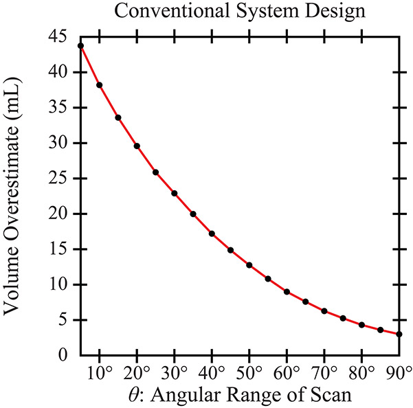
In the conventional design, Figure 4 quantifies the volume overestimation in the reconstruction relative to the input phantom (625.9 mL in volume). There is a clear benefit to increasing the scan range (). For example, the volume overestimates are 29.6 mL (4.7%) and 14.9 mL (2.4%) for scan ranges of 20° and 45°, respectively. For the purpose of this figure, much narrower and wider ranges than those used clinically are considered. This figure presumes that the detector is sufficiently wide to measure signal in a system with broad source motion.
Figure 4.
The volume of the phantom is overestimated in the reconstruction. The use of a wide angular range helps to reduce the volume overestimation.
3.2. Simulation of NGT Design
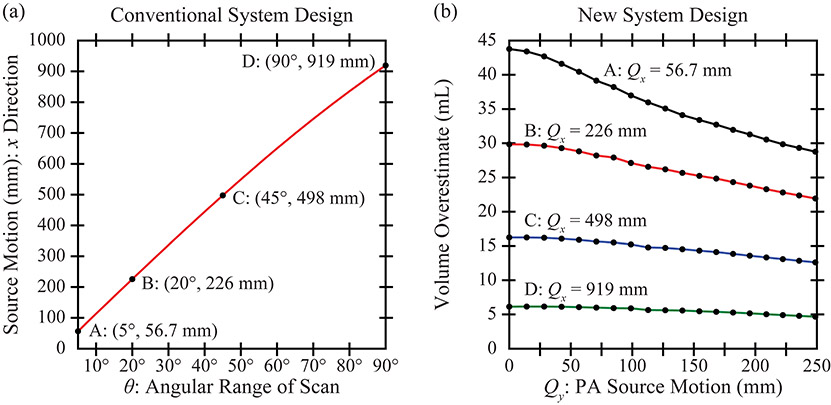
Figure 5(a) shows how the lateral () distance traversed by the source can be calculated from the angular range, , in a conventional system. Four ranges are considered for the NGT simulation; namely, 56.7, 226, 498, and 919 mm. Of the four, the middle two are representative of those used clinically. The remaining two are extremes that are useful for the purpose of a thought experiment.
Figure 5.
(a) This plot analyzes how the net motion of the source varies with the angular range of the scan. (b) The NGT design is simulated with source motion in the (PA) direction. Increasing the range of source motion in either the or direction improves the accuracy of the breast outline segmentation.
In Figure 5(b), the volume overestimate is plotted as a function of the range of PA source motion. As shown, increasing the PA motion results in less volume overestimation and hence a better breast segmentation. The relative benefit of PA motion is most pronounced in a system with a narrow scan range, . For example, comparing 0 to 249 mm of PA source motion, the percent change in the volume overestimate is 34.3% assuming , yet is 23.9% assuming .
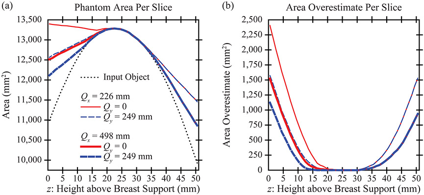
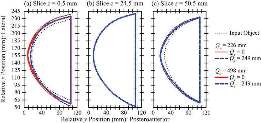
In DBT, the reconstruction is prepared with slices parallel to the breast support. Figure 6(a) calculates the area in each slice. There is effectively no area overestimation in the central slices of the stack [Figure 6(b)], an example of which is visualized in Figure 7(b). The -coordinate of this slice is 24.5 mm. The breast outline is effectively the same in all acquisition geometries considered.
Figure 6.
(a) The area in each slice is overestimated in the reconstruction. The use of a wide angular range or of broad PA source motion helps to reduce the area overestimation. (b) The area overestimation varies by slice. Slices closest to the breast support (left side of plot) are characterized by the most area overestimation.
Figure 7.
(a) The area overestimation in the reconstruction is illustrated for the slice that is directly touching the breast support. (b) By contrast, in a slice that is 24.5 mm above the breast support (one of the central slices in the reconstruction), the area overestimation is minimal. (c) There is area overestimation in the most superior slice, similar to (a).
By contrast, there is more pronounced area overestimation in the most inferior and superior slices of the stack. These results are visualized in slice [Figure 7(a)] and [Figure 7(c)]. In the most inferior slice [Figure 7(a)], the area overestimation can be minimized by increasing the range of source motion in either the or direction. However, in the most superior slice [Figure 7(c)], the artifact is minimized only by increasing the range of source motion in the direction.
3.3. Experimental Results
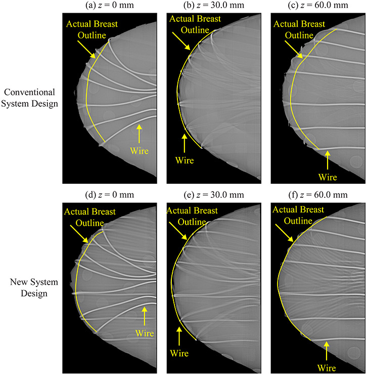
To validate these results experimentally, the Mammo II phantom was analyzed with the NGT system. Figure 8 shows slices in the reconstruction prepared with Piccolo™ (Real Time Tomography, LLC, Villanova, PA). Each subfigure is 80.0 mm × 175.0 mm. Seven wires were wrapped around the phantom. Since the wires are thin and high contrast, their exact location can be determined from the reconstruction, and thus their purpose is to identify the actual surface of the breast. In the central slice (), the breast outline matches the outline defined by the wires. This result holds in both the conventional and the NGT designs [Figure 8(b) and 8(e)].
Figure 8.
To identify the actual breast outline in the reconstruction, seven wires were wrapped around the Mammo II phantom. Images were acquired with our prototype NGT system. Reconstruction slices are shown at three positions relative to the breast support in both the conventional design [(a)-(c)] and the new design with T-shaped source motion [(d)-(f)].
By contrast, in the most superior and inferior slices, there is a clear difference between the two system designs. The conventional design is characterized by an area overestimation artifact [Figure 8(a) and 8(c)]. To the left of the actual breast outline (shown in yellow), the wires are blurred; this indicates that this breast tissue is artefactual. Figure 8(d) and 8(f) show that the NGT design helps to minimize this artifact.
4. DISCUSSION AND CONCLUSION
This paper demonstrates that the breast volume is overestimated in DBT reconstruction. For conventional DBT systems, we showed that this artifact can be minimized by increasing the angular range of the scan. There are mechanical limits to how broad of a motion can be supported by the source, and thus in practice, it will not be possible to eliminate the artifact completely.
To minimize the artifact further, PA source motion needs to be introduced. With the Mammo II phantom, we validated this concept using our prototype NGT system. The source motion in both the and directions needs to be as broad as possible to achieve the most accurate breast outline segmentation.
One limitation of this paper is that only one phantom is simulated. In future work, the simulation needs to include additional phantoms to investigate how the size and shape of the object impacts the breast outline segmentation. Also, the T-shaped trajectory was just one example of a motion with extent in the PA direction. Different motion paths for the source need to be considered in future work to determine whether the volume overestimation artifact can be minimized further.
Previous work has shown that oblique x-ray incidence is a source of resolution loss in detectors, degrading the modulation transfer function and detective quantum efficiency.9-16 Although a broad angular range gives rise to a more accurate breast outline segmentation, it comes with the trade-off of increased x-ray beam obliquity, and thus poorer resolution at high frequencies. To optimize the design of a DBT system in practice, the benefits and drawbacks of a wide angular range need to be carefully weighed.
ACKNOWLEDGEMENT
The authors thank Johnny Kuo, Susan Ng, and Peter Ringer of Real Time Tomography for technical assistance with Piccolo™. Andrew D. A. Maidment is a shareholder of Real Time Tomography, and is a member of the scientific advisory board.
Support was provided by the following grants: PDF14302589, IIR13264610, and IIR13262248 from Susan G. Komen®; R01CA196528, R01CA163746, and R01CA181171 from the National Institute of Health; and IRSA 1016451 from the Burroughs Wellcome Fund. In addition, equipment support was provided by Analogic Inc., Barco NV, and Real Time Tomography. The content is solely the responsibility of the authors and does not necessarily represent the official views of the funding agencies.
6. REFERENCES
- 1.Chan H-P, Goodsitt MM, Helvie MA, et al. Digital Breast Tomosynthesis: Observer Performance of Clustered Microcalcification Detection on Breast Phantom Images Acquired with an Experimental System Using Variable Scan Angles, Angular Increments, and Number of Projections Views. Radiology. 2014;273(3):675–685. [DOI] [PMC free article] [PubMed] [Google Scholar]
- 2.Mertelmeier T, Ludwig J, Zhao B, Zhao W. Optimization of Tomosynthesis Acquisition Parameters: Angular Range and Number of Projections. Lecture Notes in Computer Science. 2008;5116:220–227. [Google Scholar]
- 3.Zhao B, Zhao W. Three-dimensional linear system analysis for breast tomosynthesis. Medical Physics. 2008;35(12):5219–5232. [DOI] [PMC free article] [PubMed] [Google Scholar]
- 4.Maidment TD, Vent TL, Ferris WS, Wurtele DE, Acciavatti RJ, Maidment ADA. Comparing the Imaging Performance of Computed Super Resolution and Magnification Tomosynthesis. Paper presented at: SPIE Medical Imaging2017; Orlando, FL. [Google Scholar]
- 5.Acciavatti RJ, Mannherz W, Nolan M, Maidment ADA. An Alternate Design for the Defrise Phantom To Quantify Resolution in Digital Breast Tomosynthesis. Paper presented at: SPIE Medical Imaging2017; Orlando, FL. [Google Scholar]
- 6.Acciavatti RJ, Chang A, Woodbridge L, Maidment ADA. Optimizing the Acquisition Geometry for Digital Breast Tomosynthesis Using the Defrise Phantom. Paper presented at: SPIE Medical Imaging2014; San Diego, CA. [Google Scholar]
- 7.Kuo J, Ringer PA, Fallows SG, Bakic PR, Maidment ADA, Ng S. Dynamic Reconstruction and Rendering of 3D Tomosynthesis Images. Paper presented at: SPIE Medical Imaging2011; Lake Buena Vista, FL. [Google Scholar]
- 8.Rodriguez-Ruiz A, Agasthya GA, Sechopoulos I. The compressed breast during mammography and breast tomosynthesis: in vivo shape characterization and modeling. Physics in Medicine and Biology. 2017;62:6920–6937. [DOI] [PMC free article] [PubMed] [Google Scholar]
- 9.Que W, Rowlands JA. X-ray imaging using amorphous selenium: Inherent spatial resolution. Medical Physics. 1995;22(4):365–374. [DOI] [PubMed] [Google Scholar]
- 10.Hajdok G, Cunningham IA. Penalty on the detective quantum efficiency from off-axis incident x rays. Paper presented at: Medical Imaging 2004: Physics of Medical Imaging2004; San Diego, CA. [Google Scholar]
- 11.Mainprize JG, Bloomquist AK, Kempston MP, Yaffe MJ. Resolution at oblique incidence angles of a flat panel imager for breast tomosynthesis. Medical Physics. 2006;33(9):3159–3164. [DOI] [PubMed] [Google Scholar]
- 12.Acciavatti RJ, Maidment ADA. Calculation of OTF, NPS, and DQE for Oblique X-Ray Incidence on Turbid Granular Phosphors. Lecture Notes in Computer Science. 2010;6136:436–443. [DOI] [PMC free article] [PubMed] [Google Scholar]
- 13.Freed M, Park S, Badano A. A fast, angle-dependent, analytical model of CsI detector response for optimization of 3D x-ray breast imaging systems. Medical Physics. 2010;37(6):2593–2605. [DOI] [PMC free article] [PubMed] [Google Scholar]
- 14.Freed M, Park S, Badano A. Erratum: "A fast, angle-dependent, analytical model of CsI detector response for optimization of 3D x-ray breast imaging systems" [Med. Phys. 37, 2593-2605 (2010)]. Medical Physics. 2011;38(4):2307. [DOI] [PMC free article] [PubMed] [Google Scholar]
- 15.Badano A, Freed M, Fang Y. Oblique incidence effects in direct x-ray detectors: A first-order approximation using a physics-based analytical model. Medical Physics. 2011;38(4):2095–2098. [DOI] [PubMed] [Google Scholar]
- 16.Acciavatti RJ, Maidment ADA. Optimization of phosphor-based detector design for oblique x-ray incidence in digital breast tomosynthesis. Medical Physics. 2011;38(11):6188–6202. [DOI] [PMC free article] [PubMed] [Google Scholar]


