

Abstract

Triboelectric nanogenerators (TENGs) have been developed as promising energy-harvesting devices to effectively convert mechanical energy into electricity. TENGs use either organic or inorganic materials to initiate the triboelectrification process, followed by charge separation. In this study, a high-performance composite-based triboelectric nanogenerator (CTENG) device was fabricated, comprising polydimethylsiloxane (PDMS) as a polymeric matrix, barium titanite (BTO) nanopowders as dielectric fillers, and graphene quantum dots (GQDs) as conductive media. The PDMS/BTO/GQD composite film was prepared with GQDs doped into the mixture of PDMS/BTO and mechanically stirred. The composition of the GQD varied from 0 to 40 wt %. The composite was spin-coated onto flexible ITO on a PET sheet and dried in an oven at 80 °C for 24 h. The output performance of TENGs is enhanced by the increased concentration of 30 wt % GQD, which is 2 times higher than nanocomposite films without GQD. The PDMS/BTO/G30 TENG film depicted an increase in open-circuit voltage output (VOC), short-circuit current output (ISC), and power density reaching ∼310.0 V, ∼23.0 μA, and 1.6 W/m2, respectively. The simple and scalable process for the PDMS/BTO/GQD TENGs would benefit as a sustainable energy-harvesting system in small electronic devices.
Introduction
In the present Internet of Things (IoT) era, the demand for electricity in daily life is increasing at an unprecedented level with the popularization of portable electric and electronic devices. Normally, electricity comes from conventional fossil fuels. However, the biggest concern is the fact that fossil fuels are limited resources and nonrenewable. The use of fossil fuels also poses risks to the environment and also affects the carbon footprint. Therefore, remarkable efforts have been deployed to replace conventional fossil fuel with renewable energy sources such as solar energy, wind energy, hydroelectric energy, and many more alternative energy resources. Among various energy harvesters, the mechanical energy harvester is a promising candidate as a new-generation energy harvester capable of harvesting energy around the clock. Following the first introduction of triboelectric nanogenerators (TENGs) in 2012 by the Wang1 group that successfully reported the use of piezoelectric nanogenerators (PENGs), there has been growing interest in developing alternative methods in scavenging for the ambient mechanical energy from the environment to electricity. In TENGs, two different triboelectric materials (either organic or inorganic) were rubbed together to initiate the triboelectrification process, followed by charge separation. TENGs are relatively cheaper as compared to PENGs and they are capable of producing higher output power and can be easily fabricated.2−5 TENGs are excellent candidates for the potential application in integrated energy-harvesting devices, which convert untapped mechanical energies directly to electrical signals from various sources, such as wind flow, ocean waves, human motion, and even blood movement inside human veins.6−10 To date, various triboelectric polymeric materials have been used in TENGs, such as polymers [polyamide, polytetrafluoroethylene (PTFE), polydimethylsiloxane (PDMS), and polyvinylidene fluoride (PVDF)].11−13 In order to successfully apply TENGs as energy harvesters, these special types of generators must exhibit certain criteria such as being highly flexible, being able to maximize electrical output, and being robust in enduring high mechanical stress or strain. Even though typical TENGs consisting of the above tribomaterials are preferred due to the flexibility and good triboelectricity of the polymers, the polymer-based TENGs are facing critical issues such as the inclination of the electron to recombine with positive charges induced on an electrode and low conductivity of the triboelectric polymers.
PDMS is one of the most negative triboelectric materials frequently used in TENGs given its ability to gain electrons while being highly flexible, highly electronegative, nontoxic, and biocompatible. Due to its simple preparation conditions and physical tunability, PDMS has become a suitable choice for engineering properties in achieving high-performance TENGs. In order to increase the electronic characteristics of the PDMS-based TENG, incorporating high-dielectric inorganic materials into a PDMS matrix could promote the relative permittivity and charge density of tribomaterials, which further boost the PDMS-based TENG electrical output.11−16 Various types of high-dielectric-constant inorganics materials such as TiO2, SrTiO3, BaTiO3 (BTO), and ZnSnO317−19 were added into PDMS to improve the effectiveness of the composite film. Among all of the dielectric materials, BTO is one of the most appealing due to its high dielectric constant and ferroelectric properties making it an ideal candidate for nanogenerators.20
Graphene has been widely utilized in diverse electrical devices and constructs. In a graphene monolayer, each carbon atom is covalently bonded with other nearby atoms to construct a honeycomb-like lattice. The essential characteristics of graphene are its excellent thermal and electrical conductivity. Graphene has been reported to exhibit an electrostatic behavior and is able to store electrical charge when friction is applied, thereby creating more opportunities for the potential application of graphene in TENGs.21 Graphene can offer rich charge transfer pathways in TENGs and this leads to significant improvement in the output performance of the TENGs.22
There are also reports on the use of dispersed graphene quantum dots (GQDs) as fillers and as alternative candidates, besides the graphene and graphene oxides, to increase the dielectric constant of polymer materials.23 Unique optic, electronic, spintronic, and photoelectric properties induced by the quantum confinement effect and edge effect, including its fragments limited in size, or domains, of a single-layer two-dimensional layered structure with a large aspect ratio allow GQDs to form a large number of parallel microcapacitors within the polymer matrix.24−26
In this study, a high-performance composite-based triboelectric nanogenerator (CTENG) device based on PDMS as a polymeric matrix with BTO nanoparticles as dielectric fillers and graphene as conductive media was fabricated. The three-phase nanocomposite is observed to exhibit a percolation system, in which BTO was uniformly and randomly dispersed in the polymeric matrix and surrounded by graphene, which formed discrete microcapacitor structures. The highest-voltage-, current-, and power-density-producing PDMS/BTO/GQD nanocomposite will be found to have the best output performance. The stable and good electrical output power generated by the TENGs suggests that the device has the potential for energy harvesting in nanoenergy applications.
Materials
The materials used in this study included a silicone elastomer, silicone elastomer curing agent (SYLGARD 184 Silicone Elastomer Kit, Dow Corning), BTO nanoparticles [cubic crystalline phase, 50 nm particle size (SEM), ≥99%, Sigma-Aldrich], ITO-coated PET, and GQDs (ACS Materials). For fabrication of the PDMS/BTO composite film (refer Figure 1), 20 wt % BTO was loaded into PDMS, which was prepared by mixing silicone elastomer/silicone elastomer curing agent in a weight ratio of 10:1 and magnetically stirred. Then, the sample was spin-coated onto flexible ITO on a PET sheet (area 2 cm × 3 cm) at 1000 rpm for 60 s before drying the samples in an oven at 80 °C for 24 h.
Figure 1.

Schematic of preparation of PDMS/BTO/GQD nanocomposite for TENG devices: mixing BTO nanoparticles and GQDs with PDMS solution, casting and spin-coating the mixture, curing the mixture at high temperature, and adding electrodes for TENG devices.
The PDMS/BTO/GQD composite film was prepared using the same approach, with the GQD doped into the mixture of PDMS and BTO at various compositions between 0 and 40 wt %. The sample was spin-coated onto flexible ITO on a PET sheet (area 2 cm × 3 cm) at 1000 rpm for 60 s before the samples were dried in an oven at 80 °C for 24 h. The structural properties of the devices were characterized by field emission-scanning electron microscopy (FE-SEM, CARL ZEISS: MERLIN), an X-ray diffractometer (Bruker D8 DISCOVER), and confocal micro-Raman spectroscopy.
The active area of the composite films on the ITO was prepared with the area of 2 cm × 2 cm, and PET was used as another triboelectric electrode. Both samples were mounted on the custom-built nanogenerator tester and separated by a spring spacer. For the signal measurement, both electrodes were linked to an external circuit. During the tests, a computer-controlled push pulls linear solenoid squeezed the PET/ITO top side against the nanocomposite’s electrode at a frequency of 1 Hz. The bottom electrode was attached to the table surface to stabilize the apparatus. The voltage outputs were recorded by using an Agilent N2873A oscilloscope. For current measurement, a current-to-voltage converter circuit at a conversion ratio of 100 mV/μA was used.27
Result and Discussion
In order to determine the microstructure of PDMS/BTO/GQD nanocomposites, the samples were analyzed by X-ray diffraction (XRD). As illustrated in Figure 2, the broad diffraction patterns at 2θ = 12° indicate that the PDMS was amorphous, and the addition of BTO and GQDs did not change the bulk properties of the PDMS.
Figure 2.
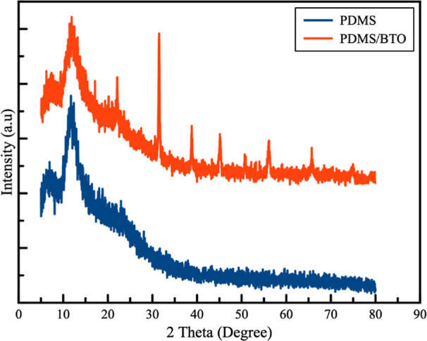
XRD patterns of PDMS and PDMS/BTO.
The XRD pattern of BTO confirms the cubic phase of BTO (JCPDS no. #892475). The peaks at 2θ = 22.12, 31.50, 38.75, 45.12, 50.23, 55.80, 65.71, and 74.75° are indexed as (100), (110), (111), (200), (210), (211), (220), and (310) diffraction planes of the cubic phase, respectively. Meanwhile, a diffraction peak observed at 2θ = 26.2° (JCPDS no.—41-1487) corresponds to the signature (002) plane of the graphene quantum dot presented in the composite sample.28
Figure 3 demonstrates the characteristic peaks of different compositions of the PDMS/BTO/GQD nanocomposite films. There are no significant comparative shifts in the diffraction position of the other polymer nanocomposite films. All the peaks of PDMS and BTO nanoparticles were present and unchanged upon the addition of different compositions of GQDs. However, it can be noticed that the diffraction peak is increased and broadens as more GQDs are added to the nanocomposites.
Figure 3.

XRD patterns of (a) PDMS, (b) PDMS/BTO, (c) PDMS/BTO/G10, (d) PDMS/BTO/G20, (e) PDMS/BTO/G30, and (f) PDMS/BTO/G40.
The presence of GQDs also has been further confirmed by Raman spectroscopy, the Raman spectrum of a PDMS/BTO/GQD (PDMS/BTO/G4) that was excited using a green laser (532 nm). The D and G peaks (Figure 4) appeared in the band that corresponded to the aromatic domain’s GQD. The peaks at 1350 cm–1 can be related to the sp3 orbital hybridized of C=C (carbon-to-carbon bonds), C=O (carbon-to-oxygen bonds), and COOH (hydroxyl group), respectively, while the peaks at 1550 cm–1 correspond to the C–C due to the sp2 carbon orbital.29
Figure 4.

Raman spectra of PDMS/BTO/G40.
Scanning electron microscopy is one of the most effective methods and is useful to elucidate the surface morphology, surface topography, and composition of materials. FE-SEM characterization has been carried out to investigate the dispersion states of the BTO and GQD in the PDMS polymer matrix. Figure 5a–f displays FE-SEM images of the neat PDMS film, PDMS/BTO, and PDMS/BTO/GQD nanocomposite films loaded with various compositions of GQD, respectively.
Figure 5.

FE-SEM images of the top surface of (a) PDMS, (b) PDMS/BTO, (c) PDMS/BTO/G10, (d) PDMS/BTO/G20, € PDMS/BTO/G30, and (f) PDMS/BTO/G40 and close-up image of (g) PDMS/BTO/G30.
The neat PDMS film exhibits a smooth surface, and the micrograph of the PDMS/BTO nanocomposite (Figure 5b) demonstrates the uniform distribution of BTO within the polymer matrix, as indicated by the small circle in the image. Upon addition of the GQD (Figure 5c,f), the samples depict the numerous wormlike particles gathered to form a stacking structure. The surface modification is clearly demonstrated in which the nanocomposite film is seen to crumple, but the BTO remains uniformly distributed, suggesting that the GQD forms a strong interaction with the host polymer PDMS. The nanocomposite films become more crumpled as the GQD concentration increases and this crumpling effect provides an increased roughness in the systems, which could be useful for the application of TENGs.30 In Figure 5g, a close-up image of the PDMS/BTO/G30 is shown. The higher magnification micrograph of PDMS/BTO/G30 with a 30% concentration of the GQD reveals a clearly crumpled surface of the nanocomposites. The phenomena can be explained as the increase of GQD content causing an increase in the electrostatic and π–π interactions between the GQD and PDMS. Furthermore, as the GQD concentration increases, the uniform dispersion of GQDs can create a good network between the polymer matrix, BTO, and GQD, thereby improving the dielectric of the PDMS/BTO/GQD samples.31
The electrical characteristics of PDMS/BTO/GQD-based TENGs were evaluated by using a vertical contact-separation mode at a frequency of 1 Hz. All TENGs were subjected to an identical force and a 10 mm separation distance between the composite film and field-effect transistor (FET) films. The working mechanism of the PDMS/BTO/GQD-based TENGs is described as follows: At the initial state as shown in Figure 6a, the upper electrode (PET) was separated from the PDMS nanocomposite film, and there is no potential difference since there is no initial charge between the substrate and the electrodes.
Figure 6.

Working mechanism of the TENGs based on the vertical contact-separation mode at a frequency of 1 Hz.
Then, the upper electrode was compressed by an external force and moved into contact with the PDMS/BTO/GQD composite film. The static charges were generated; refer to Figure 6b. During the frictional process, PDMS/BTO/GQD and PET, which have high triboelectric negative and positive charges, tend to gain and lose electrons. The triboelectric effect causes positive charges on the PET, while negative charges are formed on the PDMS/BTO/GQD substrate. The electron no longer flows to the external circuit as the oppositely polarized inducted charges have reached equilibrium. Upon release of the external compression force, the electrostatic field is developed. As the distance between the two layers increases as shown in Figure 6c, the electric potential difference between the two layers is enhanced, thus allowing the electrons to flow and generate an instantaneous current. Finally, the electron is redistributed as balance when the triboelectric charges reach equilibrium again when the film is completely separated; refer to Figure 6d. The voltage output signal is produced repeatedly by contacting and separating the two electrodes using external force.
The experimental setup used for the measurements was adopted from the current-to-voltage electronic circuit.27 An Agilent N2873A oscilloscope was used for output voltage measurements. The current output for triboelectric energy harvesters is very small in the range of μA, which is difficult to be measured directly. The current-to-voltage converter with a conversion ratio of 100 mV/μA has been assembled with the feedback resistor (100 kΩ), the output voltage Vo and input current Iin is equal to the feedback resistor Rf, (Vo/Iin = −Rf) in the LMC6001 op-amp inverting configured.32 The voltage and current have been measured simultaneously on Channel-1 and Channel-2, respectively. The instantaneous peak power of a TENG with an external resistance can be expressed as P = I2R where P is the instantaneous peak power, I is the current, and R is the resistance.
Table 1 presents the voltage readings according to the weight percentage of BTO from 0 to 30%. It was found that the PDMS/20BTO combination recorded the highest voltage.
Table 1. Voltage Performance of the PDMS/BTO TENGs from 0 to 30 wt % of BTO.
| samples design | BTO (wt %) | VOC (V) |
|---|---|---|
| PDMS | 0 | 73 |
| PDMS/B5 | 5 | 86 |
| PDMS/B10 | 10 | 95 |
| PDMS/B15 | 15 | 122 |
| PDMS/B20 | 20 | 156 |
| PDMS/B25 | 25 | 132 |
| PDMS/B30 | 30 | 128 |
Therefore, a weight percentage of 20% has been chosen for the mixture with GQDs. The PDMS/BTO/GQD composite film was prepared using the same approach, with the GQD doped into the mixture of PDMS and BTO at various compositions between 0 and 40 wt %.
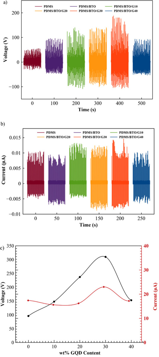
Figure 7a shows the voltage output performance of the fabricated TENG devices with different concentrations of PDMS/BTO/GQD composite films. The highest open-circuit voltage (VOC) for the TENGs with the PDMS/BTO/G30 film is ∼310.0 V. The VOC without the addition of GQDs can be shown in the sample PDMS/BTO as ∼156.0 V.
Figure 7.
(a) VOC, (b) ISC, and (c) their peak-to-peak value of the PDMS/BTO-based TENGs as a function of GQD content at pressing frequencies of 1 Hz.
As shown in the measured short-circuit current output (ISC) of the corresponding sample of Figure 7b, the positive–negative peaks were repeated at pushing–separating points. Under 10 N/1 Hz of pushing force/frequency, the averaged output current was obtained as ∼10.0 μA for the PDMS/BTO sample; the current is observed to gradually increase when the GQD is added to the matrix. The highest current output recorded, ∼23.0 μA, was also found on the PDMS/BTO/G30 sample.
The higher output performance of the PDMS/BTO/GQD-based TENG can be attributed to the following reasons: BTO is a good piezoelectric material and when the piezoelectric is added into the triboelectric system, the piezoelectric effects can significantly enhance the performance of the TENG.33 When a mechanical force is applied, the triboelectric material PDMS, which contains piezoelectric BTO, undergoes deformation, leading to an immediate demonstration of piezoelectricity. The piezoelectric effect of BTO produced the supplementary surface charges, thus reinforcing the triboelectric charge during simultaneous contact electrification and ultimately boosting the voltage outputs. The performance of TENGs is closely related to the dielectric properties of the triboelectric materials. The dielectric improvement of the triboelectric materials can improve the charge-trapping capability which enhances the surface charge density of the PDMS matrix and results in high output performance of the TENGs.34,35 The TENGs’ structure can be treated as an equivalent electric circuit model, which is simplified as three capacitors connected in series.36 The triboelectric potential (V) for the TENG can be described as follows
| 1 |
where σ and Q are the surface charge density and the induced charges distributed on the dielectric surfaces and the electrode surfaces. While d and ε represent the thickness and permittivity of the triboelectric materials, S is the electrode area, X(t) is the gap distance between two triboelectric materials surfaces, and ε0 is the vacuum permittivity.36 The surface charge density (σ), induced charges (Q), and permittivity of the dielectric materials are the key elements for the output of the TENGs. Under a fixed surface charge density (σ), the output of the TENGs can be enhanced by increasing the permittivity of the triboelectric materials. The equation shows that the permittivity increase of both triboelectric materials can enhance the electric output of the TENG. The presence of the GQD particles in the PDMS matrix is expected to provide more area for interfacial polarization, which can considerably raise the permittivity of the PDMS nanocomposites for static charge storage. When the GQD is added into the PDMS nanocomposite system, the effective permittivity of the PDMS nanocomposites also increases and greatly increases the charge density on the PDMS surface. The study also showed that the GQD played a key role in the increase of dielectric constant and reduced dielectric loss.26 The ternary structure promised the possibility of fabricating polymer composite material with excellent flexibility, high dielectric constant, and low dielectric loss by incorporating ceramic fillers and GQDs in the polymer matrix. Thus, increasing the number of GQDs will improve the capacitance of the device by simply increasing the energy storage capacity to generate a high electrical output.
It can be described that the addition of graphene in the PDMS matrix helps the electrons attracted from the PDMS matrix through the friction process to either be stored in the discrete, quantized levels of these nanosized graphene particles or trapped in the GQD dielectric. This performance improvement is attributed to the residual charges accumulated by graphene, increasing the triboelectric current. It can also be noticed from the results shown in Figure 7a,b that the electrical output performance of TENGs for PDMS/BTO/G40 was slightly reduced. The performance decreases are probably contributed by the excessive presence of GQDs on the PDMS surface, which reduces the effective contact surface area.37 When the GQDs are added beyond the optimum concentration, it also could cause the PDMS/BTO/GQD nanocomposites to agglomerate, creating an increase in the leakage current and a decreased dielectric property of the PDMS/BTO/GQD; this phenomenon can be described by percolation theory.38 Furthermore, PDMS (high tribonegativity in the triboseries table) is a much better triboelectrification material than BTO and GQD, and the decrease of the PDMS matrix surface area can also lead to the decrease in generated static charge. For validation of the theory, the use of graphene as triboelectric materials in TENGs has been compared and tabulated in Table 2.11 A peak-to-peak value in Figure 7c confirmed that the PDMS/BTO/G30 sample shows the highest VOC and ISC values. As a result, the PDMS/BTO/G30 sample was then chosen for further investigation by connecting these samples to an external load with a resistance range of 1 kΩ–30 MΩ.
Table 2. Comparison of the Graphene-Based TENGs in Vertical Contact-Separation Mode.
| negative triboelectric materials | positive triboelectric materials | device dimension (cm) | voltage (V) | current (μA) | power density (Wm2–) |
|---|---|---|---|---|---|
| PDMS/3D bilayer graphene/carbon cloth (PDMS/G/CC)22 | PET | 3.0 × 3.0 | 70 | 0.0065 | |
| PDMS/graphene31 | PET | 2.2 × 2.2 | 270.2 | ||
| 1-Layer graphene39 | PET | 5 | |||
| Graphene/EVA/PET film40 | PDMS | 3.0 × 4.0 | 22 | ||
| PDMS/GO/SDS41 | PEN | 2.0 × 2.5 | 438 | ||
| PVDF/GQD42 | Al | 6.0 × 6.0 | ∼120 | ∼3 | |
| Al-doped ZnO/GO43 | PI | 2.0 × 2.0 | 105 | ||
| PDMS/graphene-Ag nanowires44 | PDMS | 10.0 × 10.0 | |||
| GN/PTFE45 | Al | 3.0 × 3.0 | 96 | 3.66 | 3.9 |
| PI/PI:rGO/PI46 | Al | 1.5 × 2.5 | 190 | 6.3 |
As shown in Figure 8, when a load resistance is applied, the current reduces, because the charge transfer mechanism inside the resistance range is identical to the short-circuit condition. The output current approaches zero by further increasing the resistance beyond 1 MΩ. By varying the load resistance from 1 kΩ to 5 MΩ, the value of power density rises dramatically from 0.102 to 1.6 W/m2. However, as the load resistance exceeds 5 MΩ, the power density is reduced and reaches a value of 0.86 W/m2 at 30 MΩ.
Figure 8.

Maximum output current and power as a function of the external load resistance.
Therefore, it is believed that there certainly exists an optimal load resistance where the maximum output power is achieved. For validation of the performance, a comparison of the TENGs based on graphene is summarized in Table 2.
Conclusions
The PDMS/BTO/GQD nanocomposite films are scientifically investigated and applied for energy-harvesting applications. The nanocomposites were fabricated by the spin-coating method with different concentrations of GQD nanoparticles from 0 to 40 wt %. The output performance of TENGs is enhanced by the increased concentration of 30 wt % GQD which is 2 times higher than nanocomposite films without GQDs (PDMS/BTO only). The best output performance is achieved by PDMS/BTO/G30, which produces a voltage, current, and power density of ∼310.0 V, ∼ 23.0 μA, and 1.6 W/m2, respectively. The stable and good electrical output power generated by the TENGs suggests that the device has the potential for energy harvesting in nanoenergy applications.
Acknowledgments
This research was supported by the MyRA research grant 600-RMC/MyRA 5/3/LESTARI (074/2020), MyRA research grant 600-RMC/MyRA 5/3/LESTARI (076/2020), and Trans-disciplinary Research Grant Scheme TRGS/1/2019/UKM/02/1/1.
Data Availability Statement
The data underlying this study are available in the published article.
Author Contributions
Conceptualization, Faizatul Farah Hatta and Mohd Ambri Mohamed; Methodology and Experiments, Faizatul Farah Hatta performed the experiments with the assistance of Muhammad Aniq Shazni Mohammad Haniff and Mohd Ambri Mohamed; Writing—original draft preparation, Faizatul Farah Hatta; Writing—review and editing, Muhammad Aniq Shazni Mohammad Haniff and Mohd Ambri Mohamed; Supervision, Muhammad Aniq Shazni Mohammad Haniff and Mohd Ambri Mohamed; All authors have read and agreed to the published version of the manuscript.
The authors declare no competing financial interest.
References
- Wang Z. L. Nanopiezotronics,. Adv. Mater. 2007, 19 (6), 889–892. 10.1002/adma.200602918. [DOI] [Google Scholar]
- Chen X.; Li C.; Grätzel M.; Kostecki R.; Mao S. S. Nanomaterials for renewable energy production and storage,. Chem. Soc. Rev. 2012, 41 (23), 7909–7937. 10.1039/c2cs35230c. [DOI] [PubMed] [Google Scholar]
- Wang Z. L.; Song J. Piezoelectric Nanogenerators Based on Zinc Oxide Nanowire Arrays Author(s): Zhong Lin Wang and Jinhui Song Source:,. Science 2006, 312 (5771), 242–246. 10.1126/science.1124005. [DOI] [PubMed] [Google Scholar]
- Park K.; Son J. H.; Hwang G.; Jeong C. K.; Ryu J.; Koo M.; Choi I.; Lee S. H.; Byun M.; Wang Z. L.; et al. Highly-efficient, flexible piezoelectric PZT thin film nanogenerator on plastic substrates,. Adv. Mater. 2014, 26 (16), 2514–2520. 10.1002/adma.201305659. [DOI] [PubMed] [Google Scholar]
- Wang Z. L.; Wu W. Nanotechnology-enabled energy harvesting for self-powered micro-/nanosystems,. Angew. Chem., Int. Ed. 2012, 51 (47), 11700–11721. 10.1002/anie.201201656. [DOI] [PubMed] [Google Scholar]
- Lee K. Y.; Gupta M. K.; Kim S. W. Transparent flexible stretchable piezoelectric and triboelectric nanogenerators for powering portable electronics,. Nano Energy 2015, 14, 139–160. 10.1016/j.nanoen.2014.11.009. [DOI] [Google Scholar]
- Qi Y.; McAlpine M. C. Nanotechnology-enabled flexible and biocompatible energy harvesting,. Energy Environ. Sci. 2010, 3 (9), 1275–1285. 10.1039/c0ee00137f. [DOI] [Google Scholar]
- Wang Z. L. Self-powered nanosensors and nanosystems,. Adv. Mater. 2012, 24 (2), 280–285. 10.1002/adma.201102958. [DOI] [PubMed] [Google Scholar]
- Wang Z. L. Triboelectric nanogenerators as new energy technology and self-powered sensors - Principles, problems and perspectives,. Faraday Discuss. 2014, 176, 447–458. 10.1039/C4FD00159A. [DOI] [PubMed] [Google Scholar]
- Wang Z. L.; Yang R.; Zhou J.; Qin Y.; Xu C.; Hu Y.; Xu S. Lateral nanowire/nanobelt based nanogenerators, piezotronics and piezo-phototronics,. Mater. Sci. Eng., R 2010, 70 (3–6), 320–329. 10.1016/j.mser.2010.06.015. [DOI] [Google Scholar]
- Hatta F. F.; Mohammad Haniff M. A. S.; Mohamed M. A. A review on applications of graphene in triboelectric nanogenerators,. Int. J. Energy Res. 2022, 46 (2), 544–576. 10.1002/er.7245. [DOI] [Google Scholar]
- Zheng R.; Chen Y.; Chi H.; Qiu H.; Xue H.; Bai H. 3D Printing of a Polydimethylsiloxane/Polytetrafluoroethylene Composite Elastomer and its Application in a Triboelectric Nanogenerator,. ACS Appl. Mater. Interfaces 2020, 12 (51), 57441–57449. 10.1021/acsami.0c18201. [DOI] [PubMed] [Google Scholar]
- Choi K. H.; Park S.; Hyeong S. K.; Bae S.; Hong J. M.; Kim T. W.; Lee S. H.; Ryu S.; Lee S. K. Triboelectric effect of surface morphology controlled laser induced graphene,. J. Mater. Chem. A 2020, 8 (38), 19822–19832. 10.1039/D0TA05806H. [DOI] [Google Scholar]
- Ng K. E.; Ooi P. C.; Shazni Mohammad Haniff M. A.; Goh B. T.; Dee C. F.; Chang W. S.; Razip Wee M. M.; Mohamed M. A. Performance of all-solution-processed, durable 2D MoS2 flakes–BaTiO3 nanoparticles in polyvinylidene fluoride matrix nanogenerator devices using N-methyl-2-pyrrolidone polar solvent,. J. Alloys Compd. 2020, 820 (xxxx), 153160. 10.1016/j.jallcom.2019.153160. [DOI] [Google Scholar]
- Parida K.; Thangavel G.; Cai G.; Zhou X.; Park S.; Xiong J.; Lee P. S. Extremely stretchable and self-healing conductor based on thermoplastic elastomer for all-three-dimensional printed triboelectric nanogenerator,. Nat. Commun. 2019, 10 (1), 2158. 10.1038/s41467-019-10061-y. [DOI] [PMC free article] [PubMed] [Google Scholar]
- Khandelwal G.; Maria Joseph Raj N. P.; Kim S. J. Zeolitic Imidazole Framework: Metal–Organic Framework Subfamily Members for Triboelectric Nanogenerators,. Adv. Funct. Mater. 2020, 30 (12), 1910162. 10.1002/adfm.201910162. [DOI] [Google Scholar]
- Liu Y.; Li E.; Yan Y.; Lin Z.; Chen Q.; Wang X.; Shan L.; Chen H.; Guo T. A one-structure-layer PDMS/Mxenes based stretchable triboelectric nanogenerator for simultaneously harvesting mechanical and light energy,. Nano Energy 2021, 86 (May), 106118. 10.1016/j.nanoen.2021.106118. [DOI] [Google Scholar]
- Zhao P.; Bhattacharya G.; Fishlock S. J.; Guy J. G.; Kumar A.; Tsonos C.; Yu Z.; Raj S.; McLaughlin J. A.; Luo J.; et al. Replacing the metal electrodes in triboelectric nanogenerators: High-performance laser-induced graphene electrodes,. Nano Energy 2020, 75, 104958. 10.1016/j.nanoen.2020.104958. [DOI] [Google Scholar]
- Seol M.; Kim S.; Cho Y.; Byun K.; Kim H.; Kim J.; Kim S. K.; Kim S.; Shin H.; Park S. Triboelectric Series of 2D Layered Materials,. Adv. Mater. 2018, 30 (39), 1801210. 10.1002/adma.201801210. [DOI] [PubMed] [Google Scholar]
- Bakar E. A.; Mohamed M. A.; Ooi P. C.; Wee M. M. R.; Dee C. F.; Majlis B. Y. Fabrication of indium-tin-oxide free, all-solution-processed flexible nanogenerator device using nanocomposite of barium titanate and graphene quantum dots in polyvinylidene fluoride polymer matrix,. Org. Electron. 2018, 61, 289–295. 10.1016/j.orgel.2018.06.006. [DOI] [Google Scholar]
- Panchal V.; Pearce R.; Yakimova R.; Tzalenchuk A.; Kazakova O. Standardization of surface potential measurements of graphene domains,. Sci. Rep. 2013, 3 (1), 2597. 10.1038/srep02597. [DOI] [PMC free article] [PubMed] [Google Scholar]
- Qian Y.; Sohn M.; He W.; Park H.; Subramanian K. R. V.; Kang D. J. A high-output flexible triboelectric nanogenerator based on polydimethylsiloxane/three-dimensional bilayer graphene/carbon cloth composites,. J. Mater. Chem. A 2020, 8 (33), 17150–17155. 10.1039/D0TA04341A. [DOI] [Google Scholar]
- Chen T.; Liu B. Graphene quantum dot–poly(vinylidene fluoride) composite for the preparation of asymmetric bilayer bending transducer,. J. Mater. Sci.: Mater. Electron. 2018, 29 (6), 5206–5212. 10.1007/s10854-017-8485-y. [DOI] [Google Scholar]
- Lu C.; Zhang L.; Xu C.; Yin Z.; Zhou S.; Wang J.; Huang R.; Zhou X.; Zhang C.; Yang W.; et al. Self-powered graphene quantum dot/poly(vinylidene fluoride) composites with remarkably enhanced mechanical-to-electrical conversion,. RSC Adv. 2016, 6 (71), 67400–67408. 10.1039/C6RA10831H. [DOI] [Google Scholar]
- Ning N.; Li S.; Sun H.; Wang Y.; Liu S.; Yao Y.; Yan B.; Zhang L.; Tian M. Largely improved electromechanical properties of thermoplastic polyurethane dielectric elastomers by the synergistic effect of polyethylene glycol and partially reduced graphene oxide,. Compos. Sci. Technol. 2017, 142, 311–320. 10.1016/j.compscitech.2017.02.015. [DOI] [Google Scholar]
- Chen T.; Liu B. Dielectric properties of graphene quantum dot-cobalt ferrite-poly(vinylidene fluoride) ternary composites,. Mater. Lett. 2017, 209, 163–166. 10.1016/j.matlet.2017.07.088. [DOI] [Google Scholar]
- Mallineni S. S. K.; Behlow H.; Podila R.; Rao A. M. A low-cost approach for measuring electrical load currents in triboelectric nanogenerators,. Nanotechnol. Rev. 2018, 7 (2), 149–156. 10.1515/ntrev-2017-0178. [DOI] [Google Scholar]
- Kumar S.; Ojha A. K. In-situ synthesis of reduced graphene oxide decorated with highly dispersed ferromagnetic CdS nanoparticles for enhanced photocatalytic activity under UV irradiation,. Mater. Chem. Phys. 2016, 171, 126–136. 10.1016/j.matchemphys.2015.12.008. [DOI] [Google Scholar]
- Wu Y.; Luo Y.; Qu J.; Daoud W. A.; Qi T. Sustainable and shape-adaptable liquid single-electrode triboelectric nanogenerator for biomechanical energy harvesting,. Nano Energy 2020, 75 (June), 105027. 10.1016/j.nanoen.2020.105027. [DOI] [Google Scholar]
- Kumar Y. R.; Khadheer Pasha S. K. Synergistic effect of barium titanate nanoparticles and graphene quantum dots on the dielectric properties and conductivity of poly(vinylidenefluoride-co-hexafluoroethylene) films,. Environ. Res. 2022, 204, 112297. 10.1016/j.envres.2021.112297. [DOI] [PubMed] [Google Scholar]
- Menge H. G.; Kim J. O.; Park Y. T. Enhanced triboelectric performance of modified PDMS nanocomposite multilayered nanogenerators,. Materials 2020, 13 (18), 4156. 10.3390/ma13184156. [DOI] [PMC free article] [PubMed] [Google Scholar]
- Sharma A.; Agarwal P. Triboelectric energy harvester performance enhanced by modifying the tribo-layer with cost-effective fabrication,. Mater. Res. Express 2019, 6 (6), 065514. 10.1088/2053-1591/ab0f64. [DOI] [Google Scholar]
- Sriphan S.; Vittayakorn N. Hybrid piezoelectric-triboelectric nanogenerators for flexible electronics: Recent advances and perspectives,. J. Sci.: Adv. Mater. Devices 2022, 7 (3), 100461. 10.1016/j.jsamd.2022.100461. [DOI] [Google Scholar]
- Seung W.; Yoon H.; Kim T. Y.; Ryu H.; Kim J.; Lee J.; Lee J. H.; Kim S.; Park Y. K.; Park Y. J.; et al. Boosting Power-Generating Performance of Triboelectric Nanogenerators via Artificial Control of Ferroelectric Polarization and Dielectric Properties,. Adv. Energy Mater. 2017, 7 (2), 1600988. 10.1002/aenm.201600988. [DOI] [Google Scholar]
- Cheon S.; Kang H.; Kim H.; Son Y.; Lee J. Y.; Shin H.; Kim S.; Cho J. H. High-Performance Triboelectric Nanogenerators Based on Electrospun Polyvinylidene Fluoride–Silver Nanowire Composite Nanofibers,. Adv. Funct. Mater. 2018, 28 (2), 1703778. 10.1002/adfm.201703778. [DOI] [Google Scholar]
- Shi K.; Zou H.; Sun B.; Jiang P.; He J.; Huang X. Dielectric Modulated Cellulose Paper/PDMS-Based Triboelectric Nanogenerators for Wireless Transmission and Electropolymerization Applications,. Adv. Funct. Mater. 2020, 30 (4), 1904536. 10.1002/adfm.201904536. [DOI] [Google Scholar]
- Jang S.; Oh J. H. Rapid Fabrication of Microporous BaTiO3/PDMS Nanocomposites for Triboelectric Nanogenerators through One-step Microwave Irradiation,. Sci. Rep. 2018, 8 (1), 14287. 10.1038/s41598-018-32609-6. [DOI] [PMC free article] [PubMed] [Google Scholar]
- Jin L.; Xiao X.; Deng W.; Nashalian A.; He D.; Raveendran V.; Yan C.; Su H.; Chu X.; Yang T.; et al. Manipulating Relative Permittivity for High-Performance Wearable Triboelectric Nanogenerators,. Nano Lett. 2020, 20 (9), 6404–6411. 10.1021/acs.nanolett.0c01987. [DOI] [PubMed] [Google Scholar]
- Kim S.; Gupta M. K.; Lee K. Y.; Sohn A.; Kim T. Y.; Shin K.; Kim D.; Kim S. K.; Lee K. H.; Shin H.; et al. Transparent flexible graphene triboelectric nanogenerators,. Adv. Mater. 2014, 26 (23), 3918–3925. 10.1002/adma.201400172. [DOI] [PubMed] [Google Scholar]
- Chandrashekar B. N.; Deng B.; Smitha A. S.; Chen Y.; Tan C.; Zhang H.; Peng H.; Liu Z. Roll-to-Roll Green Transfer of CVD Graphene onto Plastic for a Transparent and Flexible Triboelectric Nanogenerator,. Adv. Mater. 2015, 27 (35), 5210–5216. 10.1002/adma.201502560. [DOI] [PubMed] [Google Scholar]
- Harnchana V.; Ngoc H. V.; He W.; Rasheed A.; Park H.; Amornkitbamrung V.; Kang D. J. Enhanced Power Output of a Triboelectric Nanogenerator using Poly(dimethylsiloxane) Modified with Graphene Oxide and Sodium Dodecyl Sulfate,. ACS Appl. Mater. Interfaces 2018, 10 (30), 25263–25272. 10.1021/acsami.8b02495. [DOI] [PubMed] [Google Scholar]
- Choi G. J.; Baek S. H.; Lee S. S.; Khan F.; Kim J. H.; Park I. K. Performance enhancement of triboelectric nanogenerators based on polyvinylidene fluoride/graphene quantum dot composite nanofibers,. J. Alloys Compd. 2019, 797, 945–951. 10.1016/j.jallcom.2019.05.202. [DOI] [Google Scholar]
- Li D.; Wu C.; Ruan L.; Wang J.; Qiu Z.; Wang K.; Liu Y.; Zhang Y.; Guo T.; Lin J.; et al. Electron-transfer mechanisms for confirmation of contact-electrification in ZnO/polyimide-based triboelectric nanogenerators,. Nano Energy 2020, 75 (April), 104818. 10.1016/j.nanoen.2020.104818. [DOI] [Google Scholar]
- Xu Z.; Wu C.; Li F.; Chen W.; Guo T.; Kim T. W. Triboelectric electronic-skin based on graphene quantum dots for application in self-powered, smart, artificial fingers,. Nano Energy 2018, 49 (April), 274–282. 10.1016/j.nanoen.2018.04.059. [DOI] [Google Scholar]
- Yang P.; Wang P.; Diao D. Graphene Nanosheets Enhanced Triboelectric Output Performances of PTFE Films,. ACS Appl. Electron. Mater. 2022, 4 (6), 2839–2850. 10.1021/acsaelm.2c00334. [DOI] [Google Scholar]
- Wu C.; Kim T. W.; Choi H. Y. Reduced graphene-oxide acting as electron-trapping sites in the friction layer for giant triboelectric enhancement,. Nano Energy 2017, 32 (January), 542–550. 10.1016/j.nanoen.2016.12.035. [DOI] [Google Scholar]
Associated Data
This section collects any data citations, data availability statements, or supplementary materials included in this article.
Data Availability Statement
The data underlying this study are available in the published article.