

Abstract
As of now, there are multiple types of renewable energy sources available in nature which are hydro, wind, tidal, and solar. Among all of that the solar energy source is used in many applications because of its features are low maitainence cost, less human power for handling, a clean source, more availability in nature, and reduced carbon emissions. However, the disadvantages of solar networks are continuously depending on the weather conditions, high complexity of the solar energy storage, and lots of installation place is required. So, in this work, the Proton Exchange Membrane Fuel Stack (PEMFS) is utilized for supplying the power to the local consumers. The merits of this fuel stack are high power density, ability to work at very less temperature values, efficient heat maintenance, and water management. Also, this fuel stack gives a quick startup response. The only demerit of PEMFS is excessive current production, plus very less output voltage. To optimize the current supply of the fuel stack, a Wide Input Operation Single Switch Boost Converter (WIOSSBC) circuit is placed across the fuel stack output to improve the load voltage profile. The advantages of the WIOSSBC are less current ripples, uniform voltage supply, plus good voltage conversion ratio. Another issue of the fuel stack is nonlinear power production. To linearize the issue of fuel stack, the Grey Wolf Algorithm Dependent Fuzzy Logic Methodology (GWADFLM) is introduced in this article for maintaining the operating point of the fuel cell near to Maximum Power Point (MPP) place. The entire system is investigated by utilizing the MATLAB software.
Keywords: Boost DC-DC circuit, Conversion of voltage, Duty cycle, Fast tracing speed, Few oscillations of voltage, Good dynamic response, Plus more efficiency
Subject terms: Energy science and technology, Engineering
Introduction
From the recently presented articles, most of the review articles state that the conventional power production systems are reducing drastically because of their high cost of power production, needed more catchment area, more installation cost, produces highly hazardous gasses which are directly affecting the human beings, very high atmospheric pollutant, plus less acceptable installation in rural areas1–3. The demerits of conventional power production are limited by applying non-conventional energy sources which are majorly stated as wind, biomass, plus solar. In4, the authors applied the wind power source for the hybrid water storage systems in the agriculture field. Also, the installation of wind power production plants is increased over the last twenty years. Here, the wind blades capture the air velocity by creating the lift. As a result, the blades of the windmill start running at a moderate speed5. The wind shaft is interlinked with the power generator rotor shaft for operating the generator to produce electricity. The wind plants are installed in three ways which are land-based, offshore plus distributed wind systems. Based on the installation of wind plants on the earth, these are categorized as vertical axis windmills, plus horizontal axis windmills6. Here, the wind turbines convert the wind electricity by utilizing the aerodynamic force of the blades7.
In8, the land-based wind systems are discussed and their range is from 100 kW to several megawatts. In this land-based wind network, very large wind turbines are combined to produce the bulk amount of power for meeting the future consumer load necessity. The land-dependent windmills are adversely affecting the wild animals indirectly as well as directly. These windmills give more noise pollution, less reproduction, plus habitat9. So, offshore wind systems are utilized to limit the disadvantages of land-dependent wind networks10. The offshore windmill is highly massive and larger than the Statue of Liberty. These offshore wind power production systems do not have the transportation issue because all the big-size types of equipment are shipped by using ships, and these utilize the powerful ocean winds and generate vast energy11–14. However, the drawback of this type of windmill is the more complex infrastructure required for the base support. Also, these systems are having the challenges of maintaining high wind speed, plus strong seas15. Due to the excessive drawbacks and challenges of windmills, most of the local consumers depend on solar energy systems for producing electricity16.
Solar networks are widely applied all over the world for domestic applications. Also, the development of the solar cell was done by utilizing various semiconductor implementation technologies17. The maximum utilized solar cell efficiency is twenty to twenty-five percent. The cells are combined in various manners which are series, plus parallel for enhancing the working voltage of the solar system18. Solar modules are manufactured with the help of different cells. The solar cells can be implemented either by utilizing the one-diode or two-diode circuit type methodology19. The major problem involved in solar networks is more installation price which is compensated by applying the different power converters, plus power point identifiers. However, this system gives fluctuated power, discontinuity in power production, plus moderate atmospheric pollution20. Also, it is available excessively at mid-day time, and at night time, the overall Photovoltaic (PV) energy availability is very low. To limit these demerits, the fuel stack technology is introduced in the article21 along with the PV/wind system. This fuel stack power production is constant until an input source is available.
The fuel stack is one of the most predominant and popular devices for supplying power to automotive consumers at day time as well as nighttime22. These stacks supply the power with less fluctuations, and high robust. But the fuel stack behavior is nonlinear inverse parabolic nature. So, power production from the stack is a challenging task because of the fluctuations in the operating point of the fuel cell23. There are various categories of fuel stack technologies are available in the market which are categorized as reversible fuel stacks, Alkaline Fuel Stacks (AFS), Phosphoric Acid Fuel Stacks (PAFS), Polymer Electrolyte Membrane Fuel Stacks (PEMFS), Solid Oxide Fuel Stacks (SOFS)24. In the reversible fuel cells, the oxygen content, plus hydrogen contents are utilized as sources for producing the electricity. The available chemicals at the output side of the reversible fuel cell are water, plus other chemicals25. Here, the water content is split into hydrogen, and oxygen ions by utilizing the other renewable power sources which are wind, and solar. The major advantage of this fuel stack is supplying the electricity when the consumer requires it. Also, these types of fuel stacks store a high amount of power in the form of hydrogen26. This type of energy storage has the capability of supplying power in any emergency condition. The demerits of this type of fuel stack are moderate efficiency, plus high difficulty in managing the air inside of the fuel stack.
The demerits of the reversible fuel stacks are limited by applying the AFS27. The AFS consumes the O2, plus H2 for the production of heat, electricity, plus water. Here, the electrodes are separated with the alkaline and porous matrix saturation which is named potassium hydroxide. In the fuel cell, the alkaline is reacted with the carbon dioxide. As a result, the potassium hydroxide in the fuel cell is converted into potassium carbonate which is highly harmful to all human beings28–30. So, the alkaline fuel cell takes pure oxygen, plus purifier air to eliminate the formation of potassium carbonate. The storage of pure oxygen takes more cost in the alkaline fuel cells31. Due to that the installation cost of the AFS is increased. Also, there are two variants in the alkaline cells which are static electrolytes, plus flowing electrolytes. The static electrolyte-based AFS is used in the Apollo spacecraft. In this fuel cell, the anode side-generated water is controlled by utilizing the evaporation process32–34. Again, the evaporated water is converted into liquid form for utilizing regular use. These types of fuel stacks are used in digital cameras, toys, flashlights, plus radios. The main problem of the AFS is more internal resistance. Due to that it may give less power production, plus releases the highly inflammable toxic gasses35.
The PAFS is interfaced with the PV/wind system for charging the battery through the interleaved bidirectional power conversion circuit. In this fuel stack, phosphoric acid is utilized as an electrolyte for the chemical decomposition of oxygen gas, plus hydrogen gas36. Initially, this fuel stack is used for all commercial applications because its properties are low cost of manufacturing when equated to the AFS, more steady state stability, plus high robustness. At the anode, the hydrogen gas is splitting into four hydrogen ions, plus four electrons37. These available hydrogen ions are combined with the hydroxide ions at the cathode to generate the water. Here, both electrodes are developed by utilizing carbon paper. The temperature that withstands the ability of the fuel stack is 140 to 200 °C. The features of PAFS are CO2 tolerant, highly efficient, plus the ability to operate in all bad weather conditions. This fuel stack is applied in large vehicle systems up to the power range of 100 to 400 kW38. The drawbacks of PAFS are less power density, plus having a very aggressive electrolyte. So, the PEMFS is utilized in this work for supplying the power to the resistive load. The merits of this selected fuel stack are the ability to work at a very less temperature which is nearly equal to 80 °C, plus starts very quickly39.
The primary major issue of PEMFS is continuous disturbances on the functioning point of the fuel stack40. The functioning point disturbances of the PEMFS are mitigated with the help of various categories of power point identifiers. Based on the currently published literature survey on MPPT controllers, the power point identifiers are differentiated as nature-inspired, soft computing, plus artificial intelligence controllers. In41, the authors worked out the Improved Perturb & Observe (IP&O) method for enhancing the fuel stack efficiency by optimizing the steady-state oscillations of the functioning point of the fuel stack, plus eliminating the possibility of losing the tracking way. In this algorithm, the dynamic perturbation is utilized for the P&O controller to increase the overall PV/wind/PEMFS system efficiency at very bad atmospheric conditions42–45. Here, at the initial stage, the dynamic perturbation value is more for moving the MPP point very fast. After that, the perturbation step is selected low for compensating the converter power distortions46. However, this controller gives more power conduction losses in the hybrid power network. Also, it is applicable only where the distortions of the fuel stack MPP are not zero.
Sometimes, the fuel stack system suffers from a drift effect that occurs in the general P&O controller because of the incorrect decision that happened in the conventional controller for the first-time step change in the duty cycle47. This severe drift effect creates the quick insolation between the supply, plus load. The drift effect in the PEMFS is optimized by incorporating the change in current along with the slope of the V–I characteristics. As a result, a small change in the fuel stack MPP position is eliminated48. Also, the single-ended primary inductance power converter is utilized for studying the drift-free P&O concept. The merits of this drift-free controller are medium oscillations of MPP, plus needed very less cost for design. However, this method is not helpful for quick changes in fuel cell operating temperature. The Enhanced Incremental Conductance (EIC) concept is applied in49 to limit the disadvantages of the IP&O. This enhanced controller utilizes the quick changes of fuel stack conductance for estimating the peak power production of the PV/FS network. The demerit of the EIC is high implementation complexity when equated with the P&O. So, the GWADFLM is utilized for the selected PEMFS to adjust the duty ratio of the power-wide input converter concerning the fuel stack supply temperature. This MPPT helps to achieve the optimum duty cycle and improves the voltage conversion ratio of the converter50. The second major drawback of PEMFS is excessive supply current, plus very low voltage production. Due to this condition, the fuel stack is not directly connected to the load.
In51, the authors investigated the various categories of power electronics circuits which are generally called isolated power converter circuits, plus non-isolated circuits. The forward converter is integrated with the solar/ fuel stack-based microgrid network for the equal load sharing of the hybrid power supply. In this converter, the transformer is utilized either for enhancing the supply voltage or reducing the source power. Also, this forward topology does not utilize any type of snubber circuit for protecting the power electronic circuit. So, the voltage that appears near the switch is quite equal to the source voltage, and it needed a simplex structure for a wide range of output voltages of the PEMFS. The merits of this converter are easy operation, the ability to work with multiple isolated output voltages, less noise, plus low power system loss52. However, the forward converter needed three winding-based transformers to make the three-output terminal. As a result, the forward converter-based PV/PEMFS hybrid power system size is increased. Also, the development price of this power converter circuit is higher.
The flyback circuit topology is merged with the fuel stack system to enhance the fuel stack voltage for different partial pressures of oxygens53. The flyback circuit required an additional snubber circuit to eliminate the leakage currents in the flyback network. The push–pull converter is a popular switching power converter circuit by utilizes the transformer. The features of this converter are high stable input current, very little noise on the input line voltage, plus good efficiency when equated with the forward converter circuit. However, this push–pull circuit needed two transformers, plus required two equal opposite sources at the source terminals of the converter54. Also, there are two transistors are utilized in the push–pull converter which works with unequal voltage distribution. As a result, the overall network goes into unstable operation, and it gives highly distorted converter output voltages55.
So, the multiple port power converter circuit is applied in the article56 for interlinking the battery, fuel stack, plus PV system for high power rating electric vehicle network. In this network, the independent source control has been made by utilizing the various adaptive power point identifiers. The independent source controlling provides flexible operation, gives more regulated load voltage, plus gives effective charging to the battery. However, the disadvantages are excessive noise, more expensive of developing the circuit because it needs more passive components utilization, plus ripple current. To mitigate the disadvantages of isolated networks, the wide input operation single switch power converter circuit is utilized for resistive load-fed fuel stack system for continuous enhancement of the fuel stack voltage. The proposed electrical vehicle application DC-DC converter circuit topology is given in Fig. 1.
Figure 1.
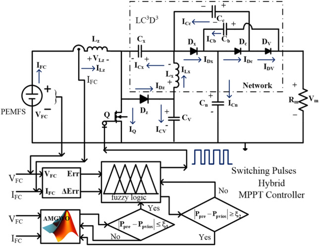
Proposed wide input operation power converter circuit with modified GWA MPPT controller.
Mathematical design and analysis of PEMFS
At present, the fuel stacks are working along with the other renewable and conventional power networks for the regulated power supply to the grid. In57–59, the authors investigated the different categories of fuel stack mathematical methodologies and their relative applications under different water membrane values of the fuel stack. The accurate parameter identification of the fuel stack is very useful for the enhancement of power system efficiency. There are various categories of swarm intelligence technologies are applied to the fuel stack to determine the exact V–I characteristics of the system. Here, the PEMFS is selected for the analysis of the proposed grey wolf-optimized fuzzy network with wide input operation-based DC-DC converter60. The polymer membrane technology-based fuel stack is developed for high-voltage-rated automotive systems. The distinguished features of this fuel stack can operate at very fewer working temperatures, has more flexibility, high robustness, quick startup, reduced corrosion, less shielding is needed, plus leakage concerns. Also, the PEMFS consists of a maximum specific per unit value of power, plus compact size.
However, the fuel stack supplies nonlinear power to stationary applications61. As a result, the functioning point of the fuel stack fluctuates continuously until it reaches the MPP place. The working of polymer membrane-dependent fuel stack structure, plus its related represented circuit diagram are explained in Fig. 2a, plus (b). From Fig. 2a, the selected fuel stack consists of flat plate electrodes which are manufactured by using the metallic bipolar plate. The electrolyte is placed in the middle of the outer layer and inner layer, and it is developed with the help of a polymer. In the electrolyte, the noble metal catalyst particles are involved. Here, the basic hydrogen is transferred to ions and it is combined with the oxygen ions. The resultant obtained electrons are transferred to the consumer, and available output water is sent to the recycling of hydrogen production. The decomposition of H2, plus oxygen O2 is illustrated in Eqs. (1), (2). From Eq. (4), the term VFC is defined as the single cell potential. The overall PEMFS voltage is evaluated by utilizing Eq. (4), (5). The terms ETVOC, VOm, VAm, plus VCm are the currently available fuel stack heat generated voltage when it is in an open circuit situation, voltage of ohmic region, active place voltage of V-I curves, plus voltage at the concentrated region of the V-I characteristics which are indicated Fig. 3a, plus (b). Similarly, the TFO, PH2, plus PO2 are the internal temperature of the cell, the pressure of hydrogen, plus oxygen. The variables RHAE, plus RHCE are the humidity vapors at the anode electrode, plus the cathode electrode. The cell anode, plus cathode inlet pressures are PAE, plus PCE. From Eqs. (7), (8), , IC, plus A are the water vapor, each cell's available current, plus the area of the electrode. Finally, the variables b1, b2, b3, plus b4 are the empirical coefficients. The PEMFS design variables are explained in Table.1.
| 1 |
| 2 |
| 3 |
| 4 |
| 5 |
| 6 |
| 7 |
| 8 |
| 9 |
Figure 2.

Proposed, (a). PEMFS structure, plus (b). Equivalent circuit of PEMFS.
Figure 3.

Obtained fuel stack, (a). V-I characteristics, plus (b). P-I characteristics.
Table 1.
PEM fuel cell stack design parameters.
| Variables | Values |
|---|---|
| Utilized rated PEMFS power | 6.0 kW |
| Applied voltage constraints of PEMFS (VMPP) | 45.01 V |
| Selected rated PEMFS current (IMPP) | 133.329A |
| Openly connected PEMFS voltage (VOC) | 65.0 V |
| Oxygen generated the limited pressure in PEMFS | 1.0 bar |
| Hydrogen generated the limited pressure in PEMFS | 1.50 bar |
| Selected cells for the design of PEMFS (N) | 65.00 |
| Fundamental air flow in cell (Ipm) | 512.02 |
| Applied gas flow constant (R) | 84.013 [J•mol-1•K−1] |
| Selected faraday parameter (F) | 95,117.444 [C•mol−1] |
| Oxygen reaction rate | 19.14% |
| Reaction of hydrogen | 99.57% |
| The completed reaction of H2 | 98.991% |
| The oxygen reaction rate in the fuel stack | 60.8% |
| Fuel stack tested working temperature | 335 K |
Design and performance evaluation of MPPT controllers
All the power point identifiers play the predominant role in the current renewable power production systems because the functioning point of the fuel stack varies from one place to another place on the V-I curve of the fuel cell62. Due to these fluctuations in the operating point of the stack, the power DC-DC converter gives highly distorted voltages to the local consumers, plus stationary applications. So, the individual MPPT methodologies are applied to the PV/PEMFS/wind power supply systems for restless monitoring of microgrid systems. In63, the researchers studied multiple types of power point identifiers for the analysis of fuel stack-based battery charging systems. The battery charging has been done by the use of multiple input bidirectional power converters. Sometimes, the individual power point identifiers for the hybrid fuel stack/battery systems may increase the implementation price. In64, the researchers applied the neural network controller for monitoring all merged renewable power production networks. In this article, there are different types of MPPT controllers are implemented and studied in terms of peak power extraction, plus settled time duration of the fuel stack voltage. The designed MPPT methodologies are multilayer perceptron feedforward neural network controller (MPFNNC), ANN with genetic algorithm (ANN with GA), dynamic step IC with FLC (DSIC with FLC), variable step hill climb with FLC (VSHC with FLC), plus grey wolf controller with FLC (GWC with FLC).
Multilayer perceptron feedforward neural network controller
The neural network controller design has been made with the help of human brain actions. The human brain consists of multiple layers with interlinked nodes65. The nodes generate the signal and its transformation has been made through dendrites. The multiple layers neural networks are developed based on the dendrites. Here, the dendrites are not combined, and they should be interlinked with some space that is identified as a synapse. From the literature survey, the ANN is developed from the dendrite's behavior and it consists of a source layer, middle layer, plus load layer. Here, the middle layers are selected based on the accuracy of the problem. When the issue is needed more accurate error then the neural network middle layers are very high. Also, the utilized nodes in the middle layer are more. As a result, the utilized model training data convergence time is greater. In66, the multiple feedforward ANN concept is applied to the power point identification controller for enhancing the efficiency of PEMFS under multiple functioning temperature values. Here, the fuel stack generated variable voltages, plus fluctuated currents are sent to the neural controller for obtaining the position of the operating point of the PEMFS. The evaluated net values of the source layer are supplied to the middle nodes for continuous improvement of weights. The operation, and weight adjustment of neurons are illustrated in Fig. 4.
| 10 |
| 11 |
| 12 |
Figure 4.

Analysis of MPPT methodology by utilizing perceptron neural network.
Based on (12), the delta concept is utilized in the neural controllers for the continuous updating of neuron weights. Where the constraints z, f, x, w, plus L are the supply variable, neuron numbers, weight of neuron, plus universal function. Also, V, r, plus c are the output signal, neuron function, plus hidden neuron output. From the evaluated signal of the neural controller, the error signal is sent to the PI network to achieve the required MPP location of the PEMFS.
| 13 |
| 14 |
| 15 |
| 16 |
Artificial neural network with GA-dependent MPPT controller
As of now, the conventional power point identifiers are not useful for the quick working conditions of the fuel stack cells. So, the current research work is going on the neural controllers for the all-nonlinear problem situations of the PEMFS. Neural controllers are more popular for all types of automotive industries for monitoring the all-electric vehicle parts' working conditions67. These networks are used to make the relationship between the different types of data sets. The features of this network are capable of handling various changes of temperatures in the fuel stack, plus it is more useful for computational system modeling. Also, the neural networks can work with multiple input parameters68. The neural controllers' working nature is quite equal to the soft computing methodologies.
The utilized neural controller with GA is explained in Fig. 5. Here, the neural controller is used to evaluate the maximum power point location by utilizing the reference voltage of the PEMFS69. In this MPPT block, the Proportional, and Integral (PI) network is applied for eliminating the fluctuations of power converter output voltages. Here, the genetic concept is applied to the Radial Basis Functional-PI controller for fine-tuning the neuron weights by comparing the basic obtained voltage signal to the reference PEMFS signal. The utilized data samples in this controller are 659. From Eq. (17), the error of the fuel stack output is monitored by utilizing the genetic concept, and the controlled signal C(x) of the utilized controller is given in Eq. (18). The terms VFC, plus VMPPre are the evaluated fuel stack voltages, plus reference peak power point voltages of the ANN controller. Also, the Cp, plus Ci variables are the PI block constraints. Finally, the Ti gives the integrator time constant.
| 17 |
| 18 |
| 19 |
| 20 |
| 21 |
| 22 |
where the constraints R, plus T are the utilized supply parameters, and W, Z, D, plus S are the neuron weights, high neuron signal, duty of the power converter, plus bias constraints for the neural controller. Also, the c, v, plus p are the neuron number, layer number, plus total neurons. Here, the plus are the data learning constraints, plus the standard deviation variable.
Figure 5.

PI network tuned neural network MPPT controller.
Dynamic step IC with FLC power point identifier for PEMFS
The basic conventional methodology of IC has the demerits of less accuracy, not being suitable for the quick variation of water membrane condition of the fuel cell, needing high convergence time, and less suitable for the complex hybrid PEMFS/battery networks70. Also, the IC works with uniform step adjustment. Due to that the IC method traces the functioning point of the proposed network with more distortions in the converter power. In71, the fuzzy methodology is interfaced in the IC block for differentiating the step constant of the incremental conductance method. So, the dynamic behavior of PEMFS is enhanced. Also, the fuzzy improves the accuracy in evaluating the settling time of the MPP under fast variations of atmospheric situations. The detailed peak power point identification of IC fed fuzzy for the fuel stack is illustrated in Fig. 6. From Fig. 6, the variable dpFc, plus dvFc are evaluated from the zero-order hold block and which are combined for identifying the error constant of the fuel stack power. The actual available slope of the PEMFS is Hn which is supplied to the fuzzy block. The fuzzy process is the slope value until the required nonlinear solution of the overall system.
Figure 6.

Enhancement of IC performance by integrating the fuzzy network.
Where Hv-old is the past slope constant of the V-I curve which is stored in the memory, and it is equated with the actual slope value for generating the new slope value (Hv-new) of the fuzzy network which is helpful for the IC method for identifying the suitable duty signal to the proposed power converter. Here, the functioning point of the PEMFS is near the origin of the V-I curve then the duty cycle adjustment has been made by utilizing Eq. (23). Otherwise, Eq. (25) is applied for moving the MPP of the cell. From Eq. (23), D(b), N, plus D(b-1) are the current duty signal, step constant, plus past existing duty signals.
| 23 |
| 24 |
| 25 |
Variable step hill climb with fuzzy MPPT controller
For all of the conventional power point identifiers, the hill climb is one of the frequently applied methods for tracing the MPP of the PEMFS72. The working concept of this HC method is nearly equal to the P&O. In this method, the current adjustment concerning the power is monitored for searching the working point of the PEMFS under rapid changes in water membrane conditions. The HC concept needed a very low price for implementation, good steady-state response, and fast understanding, required very few sensing components, plus utilized for street lighting systems73. However, the demerits of this concept are a low convergence rate, may not give the exact position of the functioning point of the cell, plus gives very little efficiency. So, the fuzzy methodology is merged with the HC block to enhance the convergence rate of the overall controller. In this combined hybrid block, initially, the HC is starting to work for capturing the V-I curve data of the cell to find out the general working point of the cell. Later the fuzzy starts finding the global functioning point of the PEMFS at the fast variation of atmospheric conditions74. The working of different step constant-based HC with fuzzy methodology is given in Fig. 7. From Fig. 7, the inputs of the controller are fuel stack current (IFC), plus voltage (VFC). The changes in fuel stack voltage (ΔV), power (ΔP), plus current (ΔI) are obtained by applying Eqs. (26), (28). The parameters P(n), P(n−1), I(n), I(n−1), D(n), plus D(n−1) are the variations in the power, current, plus duty value of the power converter.
| 26 |
| 27 |
| 28 |
Figure 7.
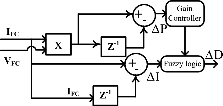
Identification of optimum duty signal by utilizing the fuzzy with HC controller.
Proposed grey wolf algorithm dependent fuzzy logic controller
Generally, the neural networks needed high training data for an accurate finding of the PEMFS MPP position. The major issues of neural networks are overfitting, limited interpretability, plus more computational complexity. These drawbacks are limited by utilizing fuzzy networks. In75, the authors focused on the fuzzy controller for efficient power distribution in the hybrid PV/battery/PEMFS power supply network. The fuzzy MPPT controller traces the MPP of renewable power networks in a very fast manner. But it may not be applicable for continuous changes of hydrogen, and oxygen pressures of the fuel stack. Also, the identification of appropriate membership function selection for the fuzzy is one of the major tasks to improve the MPP tracking accuracy of the PEMFS. Here, the grey wolf methodology is considered for the identification of proper membership value for the fuzzy controller. As a result, the proposed controller gives high tracing efficiency, quick dynamic response, very few distortions across the MPP, applicable for all types of fuel stack-based standalone applications, plus good flexibility. The Pseudo code of the introduced converter and its related working flow are illustrated in Figs. 8 and 9.
Figure 8.

Detailed analysis of proposed Pseudo code for grey wolf controller-based fuzzy.
Figure 9.

Proposed fuzzy membership functions handled by grey wolf methodology.
From Fig. 8, the hybrid controller utilizes the all variables of the fuel stack network, plus a power converter for the generation of switching signals to the wide input voltage supply-based DC-DC converter. Here, all the wolfs interchange their information in the entire search engine of the V-I curve of the fuel stack power production system. Also, each wolf runs at different velocities in various directions to reach the best optimal position of the controller. Finally, the grey wolf controller completes the multiple iterations to reach the required object. The obtained signal of the grey wolf block is supplied to the fuzzy controller for testing whether the controller either reached the MPP location or not which is mentioned in Eq. (29). Similarly, the fuzzy starts finding the MPP of the PEMFS. Once, the fuel stack reaches the global working power point then the fuzzy feedback the signal to the GWA as given in Eq. (30).
| 29 |
| 30 |
where, the terms Pinstant, §, plus Pprevious are the currently available power from the cell, error limiting factor, plus the last determined power of the PEMFS. From Fig. 9, the fuzzy consists of three major blocks which are defuzzification, inference, plus fuzzification. The inference is designed by utilizing the membership functions Negative High (NH), Zero(ZE), Positive Compact (PC), Positive High (PH), plus Negative Compact (NC).
Design of wide input operation single switch boost converter
From the literature study, the converters are utilized for enhancing the PEMFS performance. In76, the isolated Z-source power conversion technology is applied to the PV/fuel stack network for equal voltage distribution of battery, and other local loads. This Z-network increases the passive components usage in the entire power electronics system. As a result, the voltage ripples in the PEMFS may be increased, plus the cost of the overall system is increased77. So, in this proposed PEMFS system, the wide supply voltage operation-based converter plays a predominant role because of its merits high voltage conversion ratio, few passive elements utilization, less price of design when equated with the Z-source converter, plus good dynamic voltage behavior. The converter involved one switch (Q), four semiconductor diodes (Dz, Dx, Dc, plus Dv), 2-inductors (Lz, plus Lx), 4-capacitors (Cx, Cc, CV, Cb, plus Cn), plus 1-resistor (Rm). The variables VDz, VDx, VDc, plus VDc are the respective diode voltages, and the related currents flowing through the diodes are IDz, IDx, IDc, plus IDc. The supply current charging has been done by the use of inductors which are represented as ILz, plus ILx. At the steady state functioning of PEMFS, the average voltages (VLz, and VLx) across the all-inductive elements are negligible. Similarly, the voltages that appear across the capacitors are represented as VCx, VCc, VCv, VCb, and VCn, plus its associated currents are ICx, ICc, ICv, ICb, and ICn. The detailed switches' working circumstances are shown in Table 2.
Table 2.
Analyzing the operation of wide input operation-dependent converter.
| Components | CCM & DCM-stage-I | CCM & DCM-stage-II | Only DCM stage-3 |
|---|---|---|---|
| Q | Stage-ON | Stage-OFF | Stage-OFF |
| Dz | Stage-OFF | Stage-ON | Stage-OFF |
| Dx | Stage-OFF | Stage-ON | Stage-OFF |
| Dc | Stage-OFF | Stage-ON | Stage-OFF |
| Dv | Stage-OFF | Stage-ON | Stage-OFF |
CCM & DCM of converter under stage: I
Here, the converter received the supply from the fuel stack is very high then only the switch goes in forward condition state. This wide supply voltage operation-based, converter utilizes the Metal Oxide Semiconductor Field Effect Transistor for working as a switch. The features of MOSFET are more operating temperature range, quick switching dynamic behavior, good controllability of gate voltage, acceptable source impedance, plus provide more voltage gain. Here, the MOSFET (Q) goes into working mode by collecting the signals from the MPPT controller, and the diodes (Dz, Dx, Dc, plus Dv) start moving into the cutoff region. The inductors (Lz, plus Lx) start collecting the supply source until the switch moves in the active region of the output characteristics of the MOSFET. The operation of the utilized wide supply input power-based DC-DC boost converter is given in Fig. 10. From Fig. 10a, the device Q starts working and the charged inductor currents are defined as ILz-cng, ILz-dng, ILx-cng, plus IL-dng. Similarly, the corresponding voltages are defined as VLz-cng, VLz-dng, VLx-cng, plus VL-dng respectively. Based on the high switching pulse to the MOSFET, the elements Cx, and Cv are storing the electricity, and Cc, Cb, plus Cn are delivering the electrical power supply. The charged capacitor currents are represented as ICx-cng, plus ICv-cng. Here ICc-dng, ICb-dng, plus ICn-dng are discharging parameters. The inductive voltage parameters, plus capacitor current variables are given in Eqs. (31), (32).
| 31 |
| 32 |
| 33 |
| 34 |
| 35 |
| 36 |
Figure 10.

Single switch wide input power supply converter, (a). Q-ON condition, (b). Q-OFF, plus (c). Q and diodes OFF state.
CCM & DCM of converter under stage: II & III
Here, in Stage II, the supply voltage of the gate is reduced slowly to move the switch from the active region to the cutoff region. As a result, the diodes Dz, Dx, Dc, plus Dv start functioning, and MOSFET (Q) goes into an ideal state. Also, the Cx, plus Cv elements starts giving the electrical energy to the distribution loads, and the remaining capacitors Cc, Cb, plus Cn take the energy from the PEMFS. From Fig. 10b, the available voltages from the PEMFS side inductors are given in Eq. (33), plus (34). In Stage III, from Fig. 10c, the Dz, Dx, Dc, Dv, plus Q are in a completely blocking stage, and the entire proposed PEMFS network goes in DCM. Also, the gate voltage of the MOSFET is nearly equal to zero then the average currents, plus voltages of the inductive components are neglected as illustrated in Eq. (35), plus (36). The voltage conversion ratio of the wide input voltage DC-DC converter is determined by utilizing the steady state behavior of the passive elements that are used in the currently proposed power production system. The available waveforms of the proposed system are shown in Fig. 11a, plus (b). The utilized duty value (D) to the converter is given in Eq. (41). The working time duration of the converter is TS, plus the voltage distorted time is Tx. The resistive current, plus voltage are represented as Vm, plus Im.
| 37 |
| 38 |
| 39 |
| 40 |
| 41 |
| 42 |
| 43 |
| 44 |
| 45 |
Figure 11.

(a). Utilized power converter CCM, plus (b). Utilized power converter DCM.
Comprehensive investigation of wide input source DC-DC converter
The power converter comparative explanation has been done in terms of voltage available across the diodes, ripple ratio of the converter in terms of voltage conversion proportion value, utilized passive elements in the network, plus the required number of semiconductor devices. In78, the researchers used the basic fundamental power converter for studying the fuel stack battery charging network in terms of battery states of charge, the life span of the power converter, plus the depth of discharge. This functional converter requires only one inductor, plus one switch. So, the development of this topology is very easy, needed a very low price for manufacturing, plus a good understanding of consumers. However this network does not apply to high voltage conversion ratio-based electric vehicle networks. The fundamental converter network disadvantages are limited by utilizing the quasi-source converter. This converter provides sufficient voltage gain, less voltage dependency on switches, and easy adoption for the quick functioning temperature of the fuel stacks. The overall analysis of power converter networks is explained in Table 3.
Table 3.
Detailed investigation of transformerless converters for nonconventional power generation systems.
| Network | Gain conversion | Components needed | Ground needs | Passive components | Current flow | Switch strain | Diodes strain |
|---|---|---|---|---|---|---|---|
| DSIBC79 | 2-Switches, & 2-diodes | Need | 2-Inductive, & 2-capacitive | Fluctuated | |||
| LLCPC80 | 1-Switch, & 3-diodes | Need | 2-Inductive, & 2-capacitive | Fluctuated | One | One | |
| ITTPC81 | 2-Switches, & 4-diodes | Not | 2-Inductive, & 3-capacitive | Uniform | |||
| BPC82 | 1-Diode & 1-Switch | Not | 1-Inductive & 1-capacitive | Uniform | One | One | |
| EVGPC83 | 3-Switches, & 3- diodes | Need | 2-Inductive, & 2-capacitive | Fluctuated | |||
| IQPC84 | 1-Switch & 3-Diodes | Need | 3-Inductive, & 5-capacitive | Uniform | |||
| Proposed WIOSSBC | 1-Switch & 4-Diodes | Need | 2-Inductive, & 5-capacitive | Uniform |
Simulation results of proposed PEMFS power network
The introduced wide supply-dependent PEMFS power conversion system investigation has been made by selecting the MATLAB/Simulink tool. In this proposed power conversion network, the highlighted circuit LC3D3 optimizes the potential stress of semiconductor elements. Also, it filters the sudden changes in load voltage ripples. The inductor Lz is selected as 280µH for controlling the fuel stack generated currents at different functioning temperatures of the system. The MOSFET (Q) monitors the voltages of the fuel stack renewable system. The utilized capacitors Cx, Cn, Cc, Cb plus Cv values are 28.1 µF, 22.7 µF, 22.7 µF, 28.7 µF, plus 21.62 µF respectively. The capacitor Cv protects the switch from the high supply generated voltages, and Cn maintains the load power smoothly, plus constant. Finally, the standalone resistive component value is 48 mΩ.
Analysis of wide input operation SSBC with PEMFS at 322 K
Here, the PEMFS is acting as a supply to the proposed power conversion supply network for supplying the voltage to all loads. Here, the proposed grey wolf block takes the fuel stack variables which are input source voltage, plus nonlinear fuel stack current. The grey wolf block searches the operating position of the PEMFS for giving uniform voltage to the electric vehicle network. Here, at the start, the wide operation-based DC-DC converter with PEMFS is analyzed at 322 K. In these static working temperature circumstances of the fuel stack, the available output current, plus voltage of fuel cell by applying the MPFNNC, ANN with GA, DSIC with FLC, VSHC with FLC, plus GWADFLM are 106.21 A, 41.07 V, 106.72 A, 41.09 V, 106.77 A, 41.11 V, 106.82 A, 41.19 V, 106.98 A, plus 41.22 V respectively. Similarly, the peak power delivered from the polymer membrane fuel stack, and entire system efficiency by integrating the MPFNNC, ANN with GA, DSIC with FLC, plus VSHC with FLC dependent MPPT methodologies are 4362W, 96.89%, 4385.1W, 97.12%, 4389.3W, 97.34%, 4399.9W, plus 98% respectively. The proposed MPPT controller takes very low time for settling the converter-generated power which is approximately equal to 0.015 s. Also, this controller works efficiently by generating the less MPP fluctuations. The fuel stack produced current, available voltages at cell output, plus extracted powers by integrating the hybrid controllers are shown in Fig. 12a,b, plus (c). Finally, the collection of converter currents, voltages, and their related load powers are illustrated in Fig. 12d,e, plus (f).
Figure 12.

At 322 K, (a). PEMFS current, (b). PEMFS voltage, (c). PEMFS power, (d). Converter current, (e). Converter voltage, plus (f). Converter power.
Analysis of wide input operation SSBC with PEMFS at 322 K, 348 K, plus 292 K
In this dynamic fuel stack temperature circumstance, the entire power source fluctuates with high converter voltage ripples. Also, the multilayer neural network needed a very high training time to find the exact MPP position of the fuel stack. However, the implementation of MPFNNC with fuel stack is very easy and needs very little time for manufacturing the overall network. At 348 K working temperature of the cell, the fuel stack, and wide supply capability of DC-DC converter currents, plus voltages by utilizing the MPFNNC, ANN with GA, DSIC with FLC, VSHC with FLC, plus GWADFLM are 119.35A, 43.97 V, 9.0141A, 564.80 V, 119.71A, 43.99 V, 9.1267A, 564.81 V, 119.69A, 44.21 V, 9.1714A, 565.17 V, 119.92A, 44.26 V, 9.203A, 565.28 V, 119.98A, 44.28 V, 9.213A, plus 565.71 V. The PEMFS gives 98.11% efficiency by applying the grey wolf methodology along with the fuzzy as shown in Fig. 13a, b, plus (c). Also, the converter works at 0.621 duty value. So, the single switch boost converter operates with very high efficiency in all weather conditions of the fuel stack. Also, the proposed DC-DC power conversion converter works for all types of automotive systems. The simple neural controller-based converter takes more power point identifying time for the fuel stack-fed electric vehicle network. As a result, the system does not respond to the quick variation of fuel stack functioning temperatures. The VSHC with fuzzy performance is very well when equalized with the general power point identifiers which are given in Fig. 13d, e, plus (f). The overall system performance values are given in Table 4.
Figure 13.

At dynamic temperature, (a). PEMFS current, (b). PEMFS voltage, (c). PEMFS power, (d). Converter current, (e). Converter voltage, plus (f). Converter power.
Table 4.
Detailed study of wide input operation single switch power DC-DC converter by utilizing the multiple power point tracing techniques.
| Type of controller | Fuel stack current | Fuel stack voltage | Fuel stack power | WIOSSBC output current | WIOSSBC output voltage | WIOSSBC output power | Efficiency of overall system | Settling time of power | Required dependent on PEMFS | Converter power oscillations | Complexity of MPPT |
|---|---|---|---|---|---|---|---|---|---|---|---|
| Working of PEMFS by interfacing the various MPPT methods at 322 K | |||||||||||
| MPFNNC | 106.21 A | 41.07 V | 4362.0 W | 8.275 A | 510.707 V | 4226.34 W | 96.89% | 0.037 s | Needed | High | Low |
| ANN with GA | 106.72A | 41.09 V | 4385.1W | 8.338A | 510.727 V | 4258.80W | 97.12% | 0.03 s | Needed | High | Low |
| DSIC with FLC | 106.77A | 41.11 V | 4389.3W | 8.364A | 510.773 V | 4272.54W | 97.34% | 0.022 s | Not needed | Moderate | Moderate |
| VSHC with FLC | 106.82A | 41.19 V | 4399.9W | 8.422A | 511.927 V | 4311.90W | 98.00% | 0.016 s | Not needed | Moderate | Moderate |
| GWADFLM | 106.98A | 41.22 V | 4409.7W | 8.4416A | 511.981 V | 4321.94W | 98.01% | 0.015 s | Not needed | Moderate | Moderate |
| Working of PEMFS by interfacing the various MPPT methods at 348 K | |||||||||||
| MPFNNC | 119.35A | 43.97 V | 5247.8W | 9.0141A | 564.80 V | 5091.41W | 97.02% | 0.028 s | Needed | High | Low |
| ANN with GA | 119.71A | 43.99 V | 5266.0W | 9.1267A | 564.81 V | 5154.88W | 97.89% | 0.02 s | Needed | High | Low |
| DSIC with FLC | 119.69A | 44.21 V | 5291.4W | 9.1714A | 565.17 V | 5183.45W | 97.96% | 0.018 s | Not needed | Moderate | Moderate |
| VSHC with FLC | 119.92A | 44.26 V | 5307.6W | 9.2031A | 565.28 V | 5202.50W | 98.02% | 0.015 s | Not needed | Moderate | Moderate |
| GWADFLM | 119.98A | 44.28 V | 5312.7W | 9.2136A | 565.71 V | 5212.28W | 98.11% | 0.014 s | Not needed | Moderate | Moderate |
| Working of PEMFS by interfacing the various MPPT methods at 292 K | |||||||||||
| MPFNNC | 104.90A | 39.22 V | 4114.1W | 7.772A | 508.92 V | 3954.47W | 96.12% | 0.041 s | Needed | High | Low |
| ANN with GA | 106.81A | 39.85 V | 4255.9W | 8.116A | 508.99 V | 4128.22W | 97.00% | 0.039 s | Needed | High | Low |
| DSIC with FLC | 107.07A | 39.87 V | 4266.0W | 8.122A | 509.71 V | 4143.13W | 97.12% | 0.029 s | Not needed | Moderate | Moderate |
| VSHC with FLC | 107.20A | 39.98 V | 4285.8W | 8.218A | 509.75 V | 4189.36W | 97.75% | 0.0172 s | Not needed | Moderate | Moderate |
| GWADFLM | 107.31A | 40.03 V | 4295.2W | 8.245A | 509.91 V | 4204.57W | 97.89% | 0.0163 s | Not needed | Moderate | Moderate |
Experimental validation of WIOSS DC-DC power converter
The conventional power conversion network design is quite simple. However it does not have the capability of handling the electric vehicle mechanical loads84. So, the unique switch power converter is introduced in this system for handling all categories of electric vehicles under a quick variation of environmental networks. The converter design passive components are very less when compared with the other power conversion networks. Here, the IRF-840 chip MOSFET is considered for the design of the converter circuit. This MOSFET provides different voltages at different working frequencies. The experimental prototype of a wide supply power converter is explained in Fig. 14. From Fig. 14, the utilized duty percentage for the investigation of the proposed power converter is 10%, and its pulses are produced from the analog discovery device. The driver circuit is placed in the middle of the gate and source terminals of the MOSFET. The available voltage, plus current of the MOSFET are given in Fig. 15. The converter efficiency is analyzed by applying the external power supply. The external supply voltage to the converter is 59.51 V and it is improved to 128.46 V by interfacing the network LC3D3 as given in Fig. 16. The utilized inductors, plus capacitors values for this converter are the same as previously selected in MATLAB/Simulation.
Figure 14.

Prototype model power DC-DC converter.
Figure 15.

Testing of DC-DC power conversion network by selecting 0.1 duty value.
Figure 16.

Enhancement of wide supply power converter voltage with optimal current.
Conclusion
The proposed extensive output supply-based fuel stack is designed successfully by utilizing MATLAB/Simulink software. In the first objective, the polymer membrane electrolyte fuel stack technology is selected because of its features are more power density, continuous power source, compact implementation, quick response, ability to function at very low temperatures, plus low warmup time. Also, it works effectively at quick variations of load power conditions. The fuel stack suffers from a nonlinearity issue which is overcome by utilizing the GWADFLM in the second objective. From the simulative performance results, this proposed MPPT technique gives more accurate MPP location, very few iterations, needs less time for settling the converter power, works at any fuel stack parameters variation, has low dependency on fuel stack selection, plus highly efficient for all fuel stack temperature values. Also, this proposed MPPT reduces the fuel stack current in the system. So, the system operates at low power conduction losses. In the final objective, the new converter is selected for the improvement of the voltage profile of the fuel stack. The merits of this converter are more voltage conversion capacity, less duty value for running the system, few amount of voltage stress on switches, compact size, plus high robustness.
Author contributions
All the authors are contributted equally to this article.
Data availability
The datasets used and/or analyzed during the current study are available from the corresponding author on reasonable request.
Competing interests
The authors declare no competing interests.
Footnotes
Publisher's note
Springer Nature remains neutral with regard to jurisdictional claims in published maps and institutional affiliations.
Contributor Information
C. Dhanamjayulu, Email: dhanamjayulu.c@vit.ac.in
Ali ELrashidi, Email: a.elrashidi@ubt.edu.sa.
References
- 1.Chen Z, et al. Energy, exergy and economic (3E) evaluations of a novel power generation system combining supercritical water gasification of coal with chemical heat recovery. Energy Convers. Manag. 2023 doi: 10.1016/j.enconman.2022.116531. [DOI] [Google Scholar]
- 2.Xue X, et al. Proposal and investigation of a high-efficiency coal-fired power generation system enabled by chemical recuperative supercritical water coal gasification. Energy. 2023 doi: 10.1016/j.energy.2022.126598. [DOI] [Google Scholar]
- 3.Hussaian Basha CH, Rani C. Different conventional and soft computing MPPT techniques for solar PV systems with high step-up boost converters: A comprehensive analysis. Energies. 2020;13(2):371. doi: 10.3390/en13020371. [DOI] [Google Scholar]
- 4.Hussaian Basha CH, Rani C. Performance analysis of MPPT techniques for dynamic irradiation condition of solar PV. Int. J. Fuzzy Syst. 2020;22(8):2577–2598. doi: 10.1007/s40815-020-00974-y. [DOI] [Google Scholar]
- 5.Ahmad M, Zafar MH. Enhancing vertical axis wind turbine efficiency through leading edge tubercles: A multifaceted analysis. Ocean Eng. 2023;288:116026. doi: 10.1016/j.oceaneng.2023.116026. [DOI] [Google Scholar]
- 6.Salem H, Mohammedredha A, Alawadhi A. High power output augmented vertical axis wind turbine. Fluids. 2023;8(2):70. doi: 10.3390/fluids8020070. [DOI] [Google Scholar]
- 7.Al-Gburi KAH, et al. Enhancing savonius vertical axis wind turbine performance: A comprehensive approach with numerical analysis and experimental investigations. Energies. 2023;16(10):4204. doi: 10.3390/en16104204. [DOI] [Google Scholar]
- 8.Hussaian Basha CH, et al. Development of cuckoo search MPPT algorithm for partially shaded solar PV SEPIC converter. In: Das KN, Bansal JC, Deep K, Pathipooranam P, Naidu RC, et al., editors. Soft Computing for Problem Solving: SocProS 2018. Springer; 2020. [Google Scholar]
- 9.Kiran SR, et al. Reduced simulative performance analysis of variable step size ANN based MPPT techniques for partially shaded solar PV systems. IEEE Access. 2022;10:48875–48889. doi: 10.1109/ACCESS.2022.3172322. [DOI] [Google Scholar]
- 10.Said A, et al. Optimization-based mitigation techniques of the temporary overvoltage in large offshore wind farm. IEEE Access. 2023;11:6320–6330. doi: 10.1109/ACCESS.2023.3236799. [DOI] [Google Scholar]
- 11.Zeng X, et al. Investigation of higher-harmonic wave loads and low-frequency resonance response of floating offshore wind turbine under extreme wave groups. Marine Struct. 2023 doi: 10.1016/j.marstruc.2023.103401. [DOI] [Google Scholar]
- 12.Baas P, et al. Investigating energy production and wake losses of multi-gigawatt offshore wind farms with atmospheric large-eddy simulation. Wind Energ. Sci. 2023;8(5):787–805. doi: 10.5194/wes-8-787-2023. [DOI] [Google Scholar]
- 13.Wang B, et al. A fast dimension reduction framework for large-scale topology optimization of grid-layout offshore wind farm collector systems. Int. J. Electr. Power Energ. Syst. 2023 doi: 10.1016/j.ijepes.2023.109066. [DOI] [Google Scholar]
- 14.Hussaian Basha CH, Rani C, Odofin S. A review on non-isolated inductor coupled DC-DC converter for photovoltaic grid-connected applications. Int. J. Renew. Energy Res. (IJRER) 2017;7(4):1570–1585. [Google Scholar]
- 15.De Kuyffer E, et al. Offshore windmill and substation maintenance planning with distance, fuel consumption and tardiness optimisation. Oper. Res. Perspect. 2023;10:100267. [Google Scholar]
- 16.Gonzalez JM, et al. Designing diversified renewable energy systems to balance multisector performance. Nat. Sustain. 2023;6(4):415–427. doi: 10.1038/s41893-022-01033-0. [DOI] [Google Scholar]
- 17.Sayed ET, et al. Renewable energy and energy storage systems. Energies. 2023;16(3):1415. doi: 10.3390/en16031415. [DOI] [Google Scholar]
- 18.Kasaeian A, et al. Integration of solid oxide fuel cells with solar energy systems: A review. Appl. Ther. Eng. 2023 doi: 10.1016/j.applthermaleng.2023.120117. [DOI] [Google Scholar]
- 19.Dashtaki AA, et al. Optimal management algorithm of microgrid connected to the distribution network considering renewable energy system uncertainties. Int. J. Electr. Power Energ. Syst. 2023 doi: 10.1016/j.ijepes.2022.108633. [DOI] [Google Scholar]
- 20.Rani C, Odofin S, et al. Analysis and comparison of SEPIC, Landsman and Zeta converters for PV fed induction motor drive applications. In: Rani C, Odofin S, et al., editors. 2018 International Conference on Computation of Power, Energy, Information and Communication (ICCPEIC) IEEE; 2018. [Google Scholar]
- 21.Opperman JJ, et al. Balancing renewable energy and river resources by moving from individual assessments of hydropower projects to energy system planning. Front. Environ. Sci. 2023 doi: 10.3389/fenvs.2022.1036653. [DOI] [Google Scholar]
- 22.Singh R, Oberoi AS, Singh T. Heat pipes for PEM fuel cell cooling: State of the art review. Mater. Today Proc. 2023 doi: 10.1016/j.matpr.2023.01.135. [DOI] [Google Scholar]
- 23.Mehran MT, et al. A comprehensive review on durability improvement of solid oxide fuel cells for commercial stationary power generation systems. Appl. Energ. 2023;352:121864. doi: 10.1016/j.apenergy.2023.121864. [DOI] [Google Scholar]
- 24.Basha CH, Rani C. Design and analysis of transformerless, high step-up, boost DC-DC converter with an improved VSS-RBFA based MPPT controller. Int. Trans. Electr. Energ. Syst. 2020;30(12):e12633. doi: 10.1002/2050-7038.12633. [DOI] [Google Scholar]
- 25.Basha CH, Murali M. A new design of transformerless, non-isolated, high step-up DC-DC converter with hybrid fuzzy logic MPPT controller. Int. J. Circuit Theor. Appl. 2022;50(1):272–297. doi: 10.1002/cta.3153. [DOI] [Google Scholar]
- 26.Hussaian Basha CH, et al. Mathematical design and analysis of photovoltaic cell using MATLAB/Simulink. In: Das KN, Bansal JC, Deep K, Nagar AK, Pathipooranam P, Naidu RC, et al., editors. Soft Computing for Problem Solving: SocProS 2018. Springer Singapore; 2020. [Google Scholar]
- 27.Athanasaki G, Jayakumar A, Kannan AM. Gas diffusion layers for PEM fuel cells: Materials, properties and manufacturing–A review. Int. J. Hydrog. Energ. 2023;48(6):2294–2313. doi: 10.1016/j.ijhydene.2022.10.058. [DOI] [Google Scholar]
- 28.Zeng R, et al. Design and optimization of solar energy system with hydrogen energy storage and alkaline fuel cell. Energ. Convers. Manag. 2023;295:117628. doi: 10.1016/j.enconman.2023.117628. [DOI] [Google Scholar]
- 29.Muhyuddin M, et al. Lignin-derived bimetallic platinum group metal-free oxygen reduction reaction electrocatalysts for acid and alkaline fuel cells. J. Power Sources. 2023;556:232416. doi: 10.1016/j.jpowsour.2022.232416. [DOI] [Google Scholar]
- 30.Kazula S, de Graaf S, Enghardt L. Review of fuel cell technologies and evaluation of their potential and challenges for electrified propulsion systems in commercial aviation. J. Glob. Power Propuls. Soc. 2023;7:43–57. doi: 10.33737/jgpps/158036. [DOI] [Google Scholar]
- 31.Govinda Chowdary V, et al. Hybrid fuzzy logic-based MPPT for wind energy conversion system. In: Das KN, Bansal JC, Deep K, Nagar AK, Pathipooranam P, Naidu RC, et al., editors. Soft Computing for Problem Solving: SocProS 2018. Springer Singapore; 2020. [Google Scholar]
- 32.Nadimuthu LPR, et al. Energy conservation approach for continuous power quality improvement: A case study. IEEE Access. 2021;9:146959–146969. doi: 10.1109/ACCESS.2021.3123153. [DOI] [Google Scholar]
- 33.Hussaian Basha CH, et al. Simulation of metaheuristic intelligence MPPT techniques for solar PV under partial shading condition. In: Das KN, Bansal JC, Deep K, Pathipooranam P, Naidu RC, et al., editors. Soft Computing for Problem Solving SocProS 20. Springer Singapore; 2020. [Google Scholar]
- 34.Udhay Sankar V, et al. Application of WDO for decision-making in combined economic and emission dispatch problem. In: Das KN, Bansal JC, Deep K, NagarPathipooranam AKP, Naidu RC, et al., editors. Soft Computing for Problem Solving: SocProS 2018. Springer; 2020. [Google Scholar]
- 35.Park J, Lee J. Optimizing various operational conditions of hydrazine single cell for a short stack system. Adv. Energy Sustain. Res. 2023;4(3):2200188. doi: 10.1002/aesr.202200188. [DOI] [Google Scholar]
- 36.Park C, et al. Analysis of a phosphoric acid fuel cell-based multi-energy hub system for heat, power, and hydrogen generation. Appl. Ther. Eng. 2021 doi: 10.1016/j.applthermaleng.2021.116715. [DOI] [Google Scholar]
- 37.Wilailak S, et al. Thermo-economic analysis of phosphoric acid fuel-cell (PAFC) integrated with organic ranking cycle (ORC) Energy. 2021 doi: 10.1016/j.energy.2020.119744. [DOI] [Google Scholar]
- 38.Guo X, et al. Energetic, exergetic and ecological evaluations of a hybrid system based on a phosphoric acid fuel cell and an organic rankine cycle. Energy. 2021 doi: 10.1016/j.energy.2020.119365. [DOI] [Google Scholar]
- 39.Cheng S, et al. A new hybrid solar photovoltaic/phosphoric acid fuel cell and energy storage system; Energy and exergy performance. Int. J. Hydrog. Energ. 2021;46(11):8048–8066. doi: 10.1016/j.ijhydene.2020.11.282. [DOI] [Google Scholar]
- 40.Hussaian Basha CH, Rani C. A New single switch DC-DC converter for PEM fuel cell-based electric vehicle system with an improved beta-fuzzy logic MPPT controller. Soft Comput. 2022;26(13):6021–6040. doi: 10.1007/s00500-022-07049-0. [DOI] [Google Scholar]
- 41.Kiran SR, et al. A new design of single switch DC-DC converter for PEM fuel cell based EV system with variable step size RBFN controller. Sādhanā. 2022 doi: 10.1007/s12046-022-01897-0. [DOI] [Google Scholar]
- 42.Basha, Ch Hussaian, C. Rani, and S. Odofin. Design and switching loss calculation of single leg 3-level 3-phase VSI. 2018 International Conference on Computation of Power, Energy, Information and Communication (ICCPEIC). (IEEE, 2018).
- 43.Udhay Sankar V, et al. Application of wind-driven optimization for decision-making in economic dispatch problem. In: Das KN, Bansal JC, Deep K, Nagar AK, Pathipooranam P, Naidu RC, et al., editors. Soft Computing for Problem Solving: SocProS 2018. Springer Singapore; 2020. [Google Scholar]
- 44.Murali M, et al. Design and analysis of neural network-based mppt technique for solar power-based electric vehicle application. In: Bindhu V, Tavares JMRS, Ţălu Ş, et al., editors. Proceedings of Fourth International Conference on Inventive Material Science Applications: ICIMA 2021. Springer Singapore; 2022. [Google Scholar]
- 45.Hussaian Basha CH, et al. Design and performance analysis of common duty ratio controlled zeta converter with an adaptive P&O MPPT controller. In: Saraswat M, Roy S, Chowdhury C, et al., editors. Proceedings of International Conference on Data Science and Applications. Springer Singapore; 2022. [Google Scholar]
- 46.Kandidayeni M, et al. Towards health-aware energy management strategies in fuel cell hybrid electric vehicles: A review. Int. J. Hydrog. Energ. 2022;47(17):10021–10043. doi: 10.1016/j.ijhydene.2022.01.064. [DOI] [Google Scholar]
- 47.Gupta A, Singh O. Grid connected PV system with MPPT scheme using particle swarm optimization technique. Int. J. Intell. Netw. 2021 doi: 10.5173/ijiccn/001/32. [DOI] [Google Scholar]
- 48.Rafikiran S, et al. Design and performance evaluation of solid oxide-based fuel cell stack for electric vehicle system with modified marine predator optimized fuzzy controller. Mater. Today Proc. 2022;60:1898–1904. doi: 10.1016/j.matpr.2022.01.002. [DOI] [Google Scholar]
- 49.Basha CHH, et al. An improved differential evolution optimization controller for enhancing the performance of PEM fuel cell powered electric vehicle system. Mater. Today Proc. 2022;52:308–314. doi: 10.1016/j.matpr.2021.09.011. [DOI] [Google Scholar]
- 50.Basha CH, Rani C. Application of fuzzy controller for two-leg inverter solar PV grid connected systems with high voltage gain boost converter. J. Eng. Sci. Technol. Rev. 2021 doi: 10.25103/jestr.142.02. [DOI] [Google Scholar]
- 51.Basha, CH Hussaian, et al. Design of an LPF based slider controller for THD reduction in solar PV B-4 inverter, I2019 IEEE International Conference on Electrical, Computer and Communication Technologies (ICECCT) (2019).
- 52.Verma A, et al. Automatic image caption generation using deep learning. Multimed. Tools Appl. 2023;1:17. [Google Scholar]
- 53.Basha CHH, et al. An experimental analysis of degradation of cellulosic insulating material immersed in natural ester oil for transformer. ECS Trans. 2022 doi: 10.1149/10701.18957ecst. [DOI] [Google Scholar]
- 54.Mariprasath T, et al. et al. Design and analysis of an improved artificial neural network controller for the energy efficiency enhancement of wind power plant. In: Mariprasath T, et al.et al., editors. Computational Methods and Data Engineering: Proceedings of ICCMDE 2021. Springer Nature; 2022. pp. 67–77. [Google Scholar]
- 55.Murali M, et al. Design of high step-up interleaved boost converter-fed fuel cell-based electric vehicle system with neural network controller. In: Gupta D, Goswami RS, Banerjee S, Tanveer M, Pachori RB, et al., editors. Pattern Recognition and Data Analysis with Applications. Springer Nature; 2022. pp. 789–801. [Google Scholar]
- 56.Almutairi A, et al. Multi-port pwm dc-dc power converter for renewable energy applications. Energies. 2021;14(12):3490. doi: 10.3390/en14123490. [DOI] [Google Scholar]
- 57.Wang Y, et al. Fundamentals, materials, and machine learning of polymer electrolyte membrane fuel cell technology. Energ. AI. 2020 doi: 10.1016/j.egyai.2020.100014. [DOI] [Google Scholar]
- 58.Wang Y, et al. Polymer electrolyte membrane fuel cell and hydrogen station networks for automobiles: Status, technology, and perspectives. Adv. Appl. Energy. 2021 doi: 10.1016/j.adapen.2021.100011. [DOI] [Google Scholar]
- 59.Dickinson EJF, Smith G. Modelling the proton-conductive membrane in practical polymer electrolyte membrane fuel cell (PEMFC) simulation: A review. Membranes. 2020;10(11):310. doi: 10.3390/membranes10110310. [DOI] [PMC free article] [PubMed] [Google Scholar]
- 60.Nguyen HL, et al. Review of the durability of polymer electrolyte membrane fuel cell in long-term operation: Main influencing parameters and testing protocols. Energies. 2021;14(13):4048. doi: 10.3390/en14134048. [DOI] [Google Scholar]
- 61.Arif M, Cheung SCP, Andrews J. Different approaches used for modeling and simulation of polymer electrolyte membrane fuel cells: A review. Energy Fuels. 2020;34(10):11897–11915. doi: 10.1021/acs.energyfuels.0c02414. [DOI] [Google Scholar]
- 62.Derbeli M, et al. Real-time implementation of a new MPPT control method for a DC-DC boost converter used in a PEM fuel cell power system. Actuators. 2020;9(4):105. doi: 10.3390/act9040105. [DOI] [Google Scholar]
- 63.Murali M, et al. Performance analysis of different types of solar photovoltaic cell techniques using MATLAB/simulink. In: Bindhu V, Tavares JMRS, Ţălu Ş, et al., editors. Proceedings of Fourth International Conference on Inventive Material Science Applications ICIMA 2021. Springer Singapore; 2022. [Google Scholar]
- 64.Hussaian Basha CH, et al. Design of SVPWM-based two-leg VSI for solar PV grid-connected systems. In: Das KN, Bansal JC, Deep K, Nagar AK, Pathipooranam P, Naidu RC, et al., editors. Soft Computing for Problem Solving SocProS. Springer Singapore; 2020. [Google Scholar]
- 65.Kiran SR, et al. et al. Design of artificial intelligence-based hybrid MPPT controllers for partially shaded solar PV system with non-isolated boost converter. In: Kiran SR, et al.et al., editors. Computer Vision and Robotics Proceedings of CVR. Springer Singapore; 2022. [Google Scholar]
- 66.Rafikiran S, et al. Design and performance analysis of hybrid MPPT controllers for fuel cell fed DC-DC converter systems. Energ. Rep. 2023;9:5826–5842. doi: 10.1016/j.egyr.2023.05.030. [DOI] [Google Scholar]
- 67.Reddy KR, et al. A novel on energy management strategy with maximum exploitation of renewables and EV storage in distribution networks. Int. Trans. Electr. Energy Syst. 2023 doi: 10.1155/2023/1365608. [DOI] [Google Scholar]
- 68.Abdolrasol MGM, et al. Artificial neural networks based optimization techniques: A review. Electronics. 2021;10:21. doi: 10.3390/electronics10212689. [DOI] [Google Scholar]
- 69.Garud KS, Jayaraj S, Lee M-Y. A review on modeling of solar photovoltaic systems using artificial neural networks, fuzzy logic, genetic algorithm and hybrid models. Int. J.Energy Res. 2021;45(1):6–35. doi: 10.1002/er.5608. [DOI] [Google Scholar]
- 70.Rafikiran S, et al. Design of high voltage gain converter for fuel cell based EV application with hybrid optimization MPPT controller. Mater. Today Proc. 2023 doi: 10.1016/j.matpr.2023.03.770. [DOI] [Google Scholar]
- 71.Basha CHH, et al. Design of GWO based fuzzy MPPT controller for fuel cell fed EV application with high voltage gain DC-DC converter. Mater. Today Proc. 2023 doi: 10.1016/j.matpr.2023.03.727. [DOI] [Google Scholar]
- 72.Kumbhar A, et al. et al. Reducing grid dependency and operating cost of micro grids with effective coordination of renewable and electric vehicle’s storage. In: Kumbhar A, et al.et al., editors. Soft Computing for Problem Solving Proceedings of the SocProS 2022. Springer Nature Singapore; 2023. pp. 639–653. [Google Scholar]
- 73.Hussaian CH, et al. Design of an adaptive fuzzy logic controller for solar PV application with high step-up DC–DC converter. In: Bindhu V, Tavares JMRS, Ţălu Ş, et al., editors. Proceedings of Fourth International Conference on Inventive Material Science Applications. Springer Nature; 2021. [Google Scholar]
- 74.Kiran SR, et al. Design and performance analysis of hybrid optimization MPPT controller for proton exchange membrane fuel cell system with DC-DC converter. Elsevier; 2023. [Google Scholar]
- 75.Basha CH, et al. Design of adaptive VSS-P&O-based PSO controller for PV-based electric vehicle application with step-up boost converter. In: Gupta D, Goswami RS, Banerjee S, Tanveer M, Pachori RB, et al., editors. Pattern Recognition and Data Analysis with Applications. Springer Nature Singapore; 2022. pp. 803–817. [Google Scholar]
- 76.Palati M, et al. Temperature reduction analysis of solid insulating materials dipped in natural ester plus inorganic oils. Mater. Today Proc. 2023 doi: 10.1016/j.matpr.2023.07.078. [DOI] [Google Scholar]
- 77.Sastika MD, et al. Application on home automation with smart meter. In: Shukla PK, Engelbrecht A, et al., editors. International Conference on Computer Vision and Robotics. Springer Nature Singapore; 2023. [Google Scholar]
- 78.Farhani S, et al. Design and practical study of three phase interleaved boost converter for fuel cell electric vehicle. J. Power Sour. 2020 doi: 10.1016/j.jpowsour.2020.228815. [DOI] [Google Scholar]
- 79.Saadi R, et al. A robust control of a 4-leg floating interleaved boost converter for fuel cell electric vehicle application. Math. Comput. Simul. 2020;167:32–47. doi: 10.1016/j.matcom.2019.09.014. [DOI] [Google Scholar]
- 80.Rafikiran S, et al. Application of battery storage controlling by utilizing the adaptive neural network controller at various local load conditions. In: Shukla PK, Mittal H, Engelbrecht A, et al., editors. International Conference on Computer Vision and Robotics. Springer Nature; 2023. [Google Scholar]
- 81.Prakasha PK, Prashanth V, Hussaian Basha CH. Design and analysis of sliding mode controller for solar PV two-stage power conversion system. In: Shukla PK, Mittal H, Engelbrecht A, editors. International Conference on Computer Vision and Robotics. Springer Nature; 2023. [Google Scholar]
- 82.Kim N-G, et al. High-voltage-gain soft-switching converter employing bidirectional switch for fuel-cell vehicles. IEEE Trans. Veh. Technol. 2021;70(9):8731–8743. doi: 10.1109/TVT.2021.3100008. [DOI] [Google Scholar]
- 83.Hussaian Basha, C. H., et al. Design of High Voltage Gain DC-DC Converter with Fuzzy Logic Controller for Solar PV System Under Dynamic Irradiation Conditions. In Proc. of the International Conference on Paradigms of Computing, Communication and Data Sciences: PCCDS 2022. Singapore: (Springer Nature Singapore, 2023).
- 84.Srinivasan S, et al. Neural network based MPPT control with reconfigured quadratic boost converter for fuel cell application. Int. J. Hydrogen Energ. 2021;46(9):6709–6719. doi: 10.1016/j.ijhydene.2020.11.121. [DOI] [Google Scholar]
Associated Data
This section collects any data citations, data availability statements, or supplementary materials included in this article.
Data Availability Statement
The datasets used and/or analyzed during the current study are available from the corresponding author on reasonable request.