Abstract
Metallic foam is a popular topic due to its diverse industrial applications and unique combination of properties. Metallic foam is significantly lighter than nonfoam metal materials due to its porous structure, which incorporates a substantial amount of air or voids. This lower density makes metallic foam advantageous in applications in which weight reduction is critical. This makes it ideal for the aerospace, automotive, and construction industries; also, its versatile nature continues to make it an attractive material for various industrial applications such as impact absorbers, heat exchangers, and biomedical and marine engineering. However, the choice between metallic foam and nonfoam metal also depends on other factors like mechanical properties, cost, and specific application requirements. This review describes various fabrication methods of metallic foam that include the liquid metallurgy route which uses liquid or semiliquid metal, the powder metallurgy route uses metal in powder form, metal ion, and the metal vapor route which uses electrolytic deposition method to produce metallic foam. These methods include direct gas injection, adding blowing agents in solid or liquid metals, investment casting, the addition of a space holder in the precursor, metallic ion, vapor deposition on a polymer sponge, and many more. The morphology of metallic foam depends upon the method that is chosen for fabrication, and up to 98% porosity can be achieved by these methods. Additive manufacturing for metallic foam fabrication is an emerging field based on selective laser melting and electron beam melting principles. It has exceptional possibilities for generating complicated 3D shapes and customizing the material characteristics. The main purpose of this review article is to give significant insights into the various production procedures for metallic foams to researchers, engineers, and industry experts, assisting in the selection of acceptable methods depending on individual application needs. This review investigates the manufacturing conditions for metallic foams and finally discusses their advantages, drawbacks, and obstacles in mass production. The findings add to current efforts to expand metallic foam technology and encourage its wider application across diverse sectors, opening the path for future research and development.
1. Introduction
To meet global requirements, multiple materials, such as metal, polymer, ceramics, and glass, have been utilized in a wide range of applications. The progression of science and technology developments has necessitated the development of engineering materials that are significantly more effective and efficient, which led to the development of metallic foam, which is a niche category of solid cellular metals that are manufactured by intentionally injecting pores during the manufacturing phase. Metallic foam and nonfoam metals are two materials with distinct properties and characteristics. Metallic foam is ultralight and strong due to its cellular structure, while nonfoam metals retain the physical properties of the base material. Metallic foams have characteristics that polymers, metals, ceramics, or polymer and ceramic foams do not possess; these include mechanical strength, stiffness, energy and acoustic absorption, thermal and electrical conductivity, lightweight structure, thermal control, and stability under extreme conditions. Nonfoam metals, on the other hand, retain the properties of the base material, which may not be suitable for specific applications. Metallic foam is used in industries like automotive, aerospace, and health due to its unique properties. Nonfoam metals are used when the properties of the base material need to be retained, and the application does not require the specific properties of foam. The cost of producing metallic foam is mainly associated with processing, while nonfoam metals may be more cost-effective in certain applications. Metallic foam’s high surface area can be a concern for corrosion, which can damage the foam quickly. Nonfoam metals do not have this issue, as their corrosion resistance depends on the base material. So, the choice between metallic foam and nonfoam metals mainly depends on the specific requirements of the application, such as lightweight design, energy absorption, thermal management, and cost-effectiveness.1−3 Metallic foam fabrication methods are crucial, as they determine the properties and foaming behavior of the resulting material. Common fabrication techniques include gas injection, blowing agents into molten metal, and the space holder technique using liquid and powder metallurgy routes. The choice of the fabrication method affects the mechanical properties, physical properties, porosity, and cost of the foam. The compressive strength of foams can be influenced by reinforcements and a well-defined porous structure.4 However, high fabrication costs can hinder large-scale production, making it essential to improve technologies for cost-effective and consistent quality metal foam production. Overall, the fabrication method is a critical factor in the production of metallic foams. Metallic foam production costs vary based on materials, production process, and desired properties, but some aspects such as cheap raw materials, foaming agent, supply, and demand also contribute to its lower cost compared to other materials. For example, aluminum foam is produced using the melt gas injection method, and using aluminum scrap is cost-effective.5,6 Similarly, in the blowing agent technique, metallic foam formed from carbonate blowing agents is less expensive, safer, and easier to get than hydride-blowing agents.7 The increasing demand for metallic foams in various industries can potentially reduce production costs through economies of scale.
According to a patent, the first metallic foam fabrication dates to the early 1920s and involves the use of a material precursor to make a foam.8 Since then, metallic foams have been manufactured using a variety of metals, such as aluminum, nickel, titanium, copper, magnesium, zinc, gold, tantalum, lead and lead–tin alloys, iron-based alloys, and brass.9Figure 1 shows the distinctive applications of metallic foam that distinguish them from other materials to meet the demands of multiple industries like automotive, aviation, defense, shipbuilding, energy and process industry, biomedical, mechanical engineering, and civil engineering.1,10−12
Figure 1.
Distinctive applications of metallic foams.
Metallic foam is utilized in the automotive industry as a sandwich structure for weight and stiffness and as an antivibration material.13 Metallic foams are commonly used in acoustic absorption and sound damping applications, serving as sound insulation screens and silencers for low, mid, and high frequencies.14−16 Due to their turbulent flow and high surface area as compared to dense metal, metallic foam is used as a heat exchanger in various applications such as radiators, fan-cooled heat sinks, dry cooling systems, compact high-performance heat exchangers, and crossflow heat exchangers.17−21 Metallic foams have potential applications in bioimplant applications like bone scaffolds and orthopedic implants, offering improved biocompatibility and elasticity like bone.22−26 Metallic foams offer versatile gas and fluid filtration applications, including fine filtration, effective filtration, and use as metal foam substrates.27,28
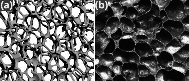
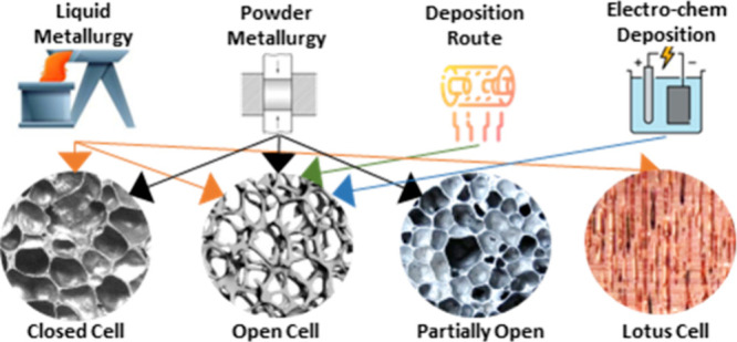
Cellular metals and porous metals are commonly used terms for metals with a high porosity volume. These openings or pores in the metallic foam are known as cells, and generally, they are classified into two types: open cell (also named as metal sponge)29 and closed cell (also named as metallic foam) as shown in Table 1. Fabrication of all these cell structures depends on the production method. Figure 2 illustrates images of open-cell and closed-cell metallic foams for better understanding.3,30−34 Closed-cell metallic foams can be used as vehicle structures, impact-absorbing material, energy absorption, and radiation shielding.10,35,36 Open-cell metallic foam used in bone implants, lightweight structural components, heat exchangers, filtration, and energy dissipation.21,37−39
Table 1. Classification of Metallic Foam Open Cell vs Closed Cell.
| open cell (metal sponge) | closed cell (metallic foam) |
|---|---|
| • Cells are complex and interconnected, making it difficult to distinguish between them. | • Cell faces and cell edges are clearly defined and not interconnected. |
| • Possesses less density | • Possesses high density |
| • Possesses high porosity and are lightweight | • High energy and crash absorption |
| • Under mechanical loading, they exhibit lower strength. | • Under mechanical loading, they exhibit high compressive strength. |
| • Mostly used as heat exchangers, filters, and catalyst carriers | • Mostly used in energy/impact absorption, vibration control, and mechanical damping. |
Figure 2.
Images illustrates classification of metallic foam: (a) open cell (left side)39 and (b) closed cell (right side).33
2. Classification of Metallic Foam Production and Processing Techniques
In recent years, advancements in metallic foam production techniques have significantly boosted their widespread adoption in commercial applications. Despite the existence of metal foam production methods since the early 1950s, their practical use was hampered by challenging processing factors and high production costs. However, over the past two decades, improvements in production techniques have overcome these hurdles, bringing a fresh wave of innovation and progress to the foam industry.6,34,40,41 In the early 1990s, Shinko Wire, Japan, made significant technological breakthroughs in production techniques, leading to a new era of foam production mith numerous commercial applications due to high demand in structural and automotive applications such as sound absorption structures used under bridges and impact absorbers in railway rolling stocks.42
Metal foams with good physical and mechanical properties are being produced with advanced manufacturing techniques and processing parameters. Depending on the required pore structure, metal foam manufacturing processes range from liquid and solid to deposition routes. For open-cell porous structures, solid or powder metallurgy is preferred, whereas liquid or melt methods are recommended for closed-cell porous structures. Metallic foam can be produced in many ways depending on the state of the metal being processed. The production process is classified into four categories, which are (a) liquid state (melt route), (b) solid state (powder metallurgy route), (c) metal vapor, and (d) metal ion solution.30,31,34,43−45
2.1. Liquid State (Melt Route)
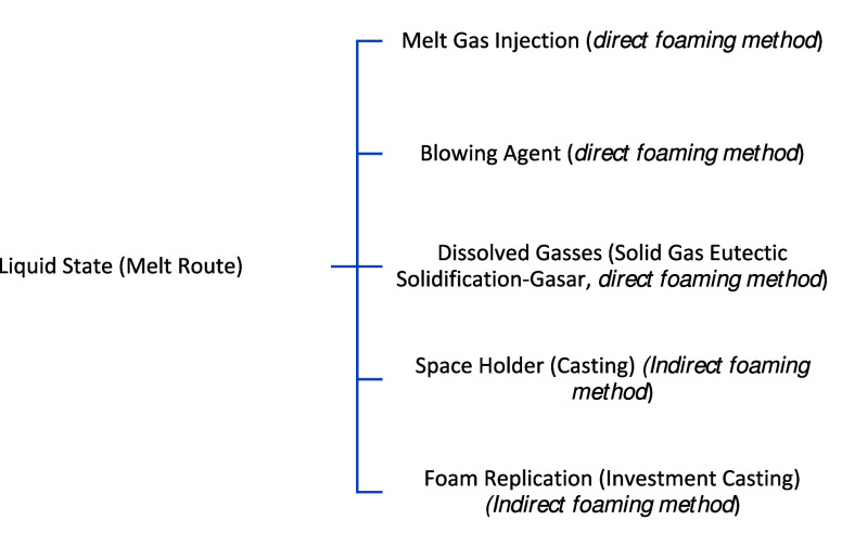
It is among the easiest methods for producing metallic foam. This method is fitting for metals and alloys with lower melting points, as the metal will be in the liquid phase, and it is easier to handle at lower temperatures. Metallic foams can be created with or without pressure. Liquid metals can be foamed directly or indirectly. Direct foaming methods involve adding gas bubbles to a molten metal, either through a capillary or frit, chemical agent, or gas dissolved in the metal while indirect foaming methods like polymer foam or by casting liquid metal around solid space-holding filler elements. These filler elements reserve space for the eventual pore structure after subsequent processing. Another viable approach involves melting powder compacts that contain a gas-releasing blowing agent. These diverse techniques offer flexibility in achieving desired metal foam structures with unique properties.45−47 The subclassification of this method is shown in Figure 3.
Figure 3.
Subclassification of metallic foam production techniques by the liquid state route.
2.1.1. Melt Gas Injection Method
Fabrication of metallic foam by the liquid metallurgy route was pioneered and patented in the 1960s and 1970s29,48−51 In the late 1980s, a resurgence of scientific activities unfolded, marked by the revival of classical methodologies and the introduction of innovative approaches. Notably, the pioneering and patenting of the melt gas injection production technique for metallic foam occurred in the early 1990s, spearheaded by Alcan International.52 Cymat (Canada) and Hydro Aluminum (Norway) are currently using this technique for commercial production of metallic foam.53−55 Their commercial applications are defense and military, architectural, lightweight cores, vibrational dampening, sound attenuation, and marine and offshore.56,57
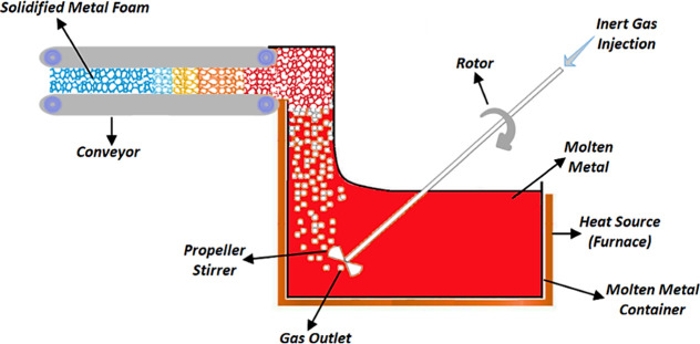
The primary idea of this technique is to produce foam by injecting gas bubbles into the liquid as illustrated in Figure 4.1,58 The first step is to prepare molten metal, and in the case of alloys, all raw materials are heated to their melting points. The second step is to inject gas into the molten metal using nozzles or specially engineered propeller stirrers (mixing heads). A controlled and consistent flow of gases plays an essential role in the cell structure and the production of high-quality metal foam. The purpose of the propeller stirrer or nozzles is to uniformly disperse tiny gas bubbles throughout the melt. To produce foam, CO2, O2, or inert gases such as air, nitrogen, argon, as well as steam can also be injected into molten metal to produce foam.3,30,59 The viscous mixture of bubbles and the metal melt floats to the surface and cools to form a solidified foam. Tiny bubbles produced through a propeller stirrer differ in size, and similarly, morphology and gas pressure will also differ for each cell in the foam. This method produces a pure, additive-free metallic foam using inert gases only. To ensure low viscosity, foam production should occur at temperatures near the melting point by bubbling gas through a continuously cooled melt in a casting process. The metallic foam produced by this method has a closed-cell structure. Foam stability plays a vital role in the production of high-quality foam it depends upon, viscosity, wetting angle, and addition of solid stabilizing particles ranging from 10 to 20% in volume fraction and 5–20 μm in size.45,47,60 Thickening agents that improve melt viscosity are Ca, SiC, Si3N4, Al2O3, TiB2, and fly ash.33,61−64 Foams have two coarsening mechanisms: disproportionation and coalescence. Disproportionation occurs due to gas pressure in different cells, leading to diffusion through the relatively thin cell walls. This leads to the elimination of some cells, resulting in a gradual increase in the average cell size. This process is identical to grain growth in metals, while coalescence leads to an increase in the mean bubble size, which converts two bubbles into one. If the coalescence rate is high, it can lead to the collapse of the foam.9
Figure 4.
Diagram of metal gas injection techniques (CYMAT & HYDRO processes).
2.1.2. Blowing Agent Method (Casting)
An alternative methodology for metallic foam production entails the direct foaming of metal melts employing a blowing agent as opposed to the conventional practice of introducing gas into the melts. This innovative approach involves controlled decomposition of the blowing agent upon heating, thereby releasing gas to instigate foaming of the molten metal. This method holds promise for further exploration and potential applications in the realm of advanced materials engineering. This is a two-stage procedure that requires heating the metal to its melting temperature and then adding blowing agents into molten metal and mixing them with a propeller stirrer to make uniform metallic foam. Choosing the appropriate blowing agent is a significant factor in this process’s effectiveness. To produce a high-quality metal foam, the blowing agent must have the ability to produce enough gas bubbles during decomposition. The metallic foam produced by this method has a closed-cell structure.42,65 The particle surface contacts, matrix alloy composition, and thermal processing conditions of blowing agent particles upon disintegration into gas are the key factors affecting the foam quality. As discussed in the preceding section, the composition, volume fraction, and size of foam stabilizing particles all have an important influence on the quality of metal foams.4,33,36,45,47,61,64 Since the 1950s, hydrides, particularly TiH2, have been the most efficient blowing agents to produce metallic foams. However, due to its exorbitant cost, efforts are being made to replace or improve it. Researchers have suggested that carbonates can be replaced with hydrides and are less expensive.3,48 The list of blowing agents used in recent years is provided in Table 2.
Table 2. List of Commonly Used Blowing Agents66,67.
| blowing agent types | chemical formulas |
|---|---|
| hydrides | TiH2, ZrH2, MgH2, CaH2, SrH2, and HfH2 |
| carbonates | CaCO3, MgCO3, BaCO3, SrCO3, and SiO2-coated CaCO3 |
Equations 1 and 2 represent the general decomposition chemical reaction equations of hydrides and carbonates respectively:
| 1 |
(hydrogen gas used as blowing gas in metallic foam fabrication).66
| 2 |
(CO2 gas used as blowing gas in metallic foam fabrication).68,69
ALPORAS is aluminum foam produced using the blowing agent technique in the batch casting process; it is an official trademark registered under the name of Shinko Wire, Japan since 1986.42 The effective distribution of the blowing agent, the effect of the thickening agent, the melting temperature, the stirring speed, and the cooling rate all play essential roles in the production of high-quality foam.33,70,71Figure 5 illustrates the schematic of the manufacturing process of ALPORAS.
Figure 5.
Diagram of the Manufacturing Process of ALPORAS.72
2.1.3. Dissolved Gases (Solid Gas Eutectic Solidification-GASAR, Direct Foaming Method)
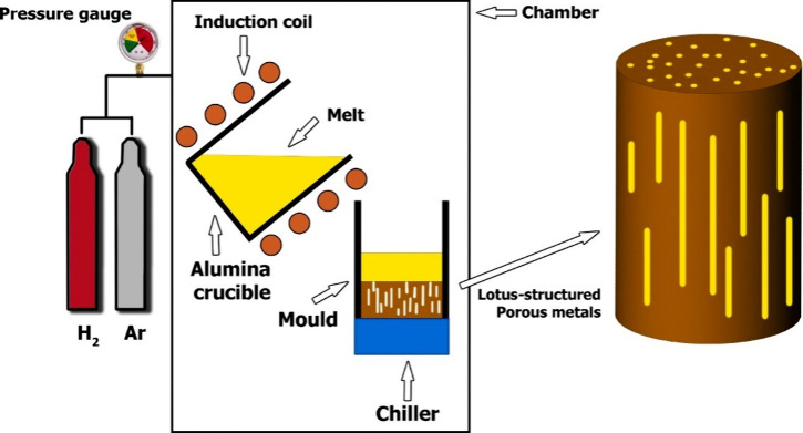
In the metal processing domain, eutectic transformations sculpt a refined two-phase microstructure, aligning the growth characteristics of the phases under specific composition and temperature conditions. Shifting focus, the GASAR method stands out as a sophisticated technique, utilizing dissolved gases through solid gas eutectic solidification. This method offers a pathway to craft porous metals by identifying systems where gases exhibit superior solubility in liquid metals compared with their solid state. Through this strategic approach, we leverage heightened gas solubility in liquid metals, paving the way for intentionally designing porous structures with distinctive properties for varied applications. This technique originated in Ukraine in the early 1990s by Shapovalov.73 The Russian abbreviation for this technique is GASAR, which stands for gas-reinforced porous material.46,74 The technique involves creating a eutectic system between hydrogen gas and liquid metals like copper, aluminum, nickel, magnesium, iron, chromium, and Al2O3-MgO.9,33,46,75 This involves melting metals under high pressure (up to 50 atm) in hydrogen atmospheres, resulting in a homogeneous melt charge with hydrogen. Lowering temperature causes the melt to undergo the eutectic transition to a heterogeneous two-phase system of “solid metal” and “gas,” resulting in gas entrapment in metal and hence directional cellular morphologies achieved.4,9,45,46,76Figure 6 illustrates a schematic of the manufacturing process of GASAR.
Figure 6.
Schematic diagram of the apparatus used for GASAR production (adapted from ref (76); Copyright 2021 Elsevier).
The morphology of these metallic foams is remarkably interesting; it represents a close-type cell structure, but these closed cells are unique. It is a novel structure featuring elongated unidirectional cylindrical pores. This type of cell structure is also known as a lotus-type cell structure as shown in Figure 7.30,32,45,77−79 Hydrogen partial pressure, cooling direction, and solidification front speed control the structure, determining pore orientation and microstructural scale.9 Typically, the solidification front advances through the liquid at velocities ranging from 0.05 to 5 mm/s. Similarly, during solidification, pore diameters range from 10 μm to 10 mm, pore lengths from 100 μm to 300 mm, and porosities from 5% to 75%.4,45
Figure 7.
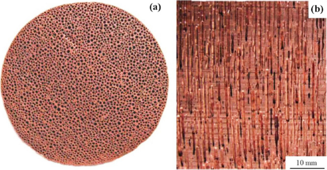
Lotus type cells structure: (a) cross sections perpendicular to the solidification direction, (b) cross sections parallel to the solidification direction.80
2.1.4. Space Holder (Infiltration Method)
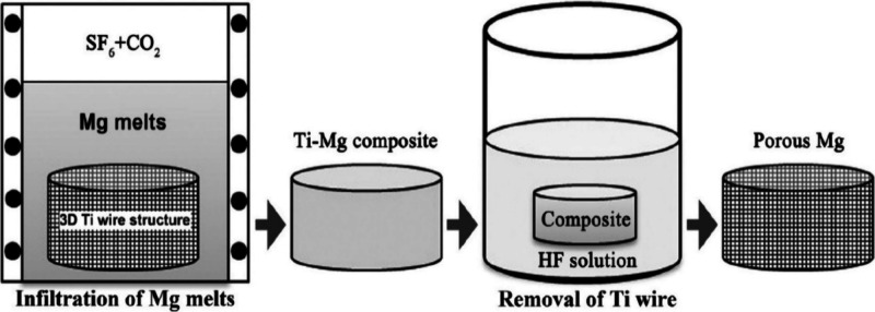
This is an intriguing method, in which metallic foam is created by introducing temporary space holders into a metal matrix, which are later removed by leaching or thermal treatment, resulting in lightweight porous metals with structural gaps known as “syntactic foam”. This method is used for manufacturing homogeneous interconnected porous structure foams. Because of its remarkable mechanical, thermal, acoustic, electrical, and chemical qualities, open-cell metallic foam has growing potential for use in a wide range of structural and functional products. The primary concept of this process is that molten metal is poured completely into a space-holder structure formed of space-holding material, such as woven wire mesh, salt beads, hollow spheres, ceramics, and polymers and then after solidification, the space-holding material is removed by acid etching9,12,64,81−84 some of the commonly used space holder material provided in Table 3.
Table 3. List of Commonly Used Space Holder Material.
| space holder type | material | melting temperatures (°C) | space holder removal method | recommended application |
|---|---|---|---|---|
| Salt beads | NaCl85 | 801 | By dissolution in water | For the preparation of aluminum foam for various industrial applications like mechanical, thermal, sound, and vibration85 |
| KCl86 | 770 | By thermal decomposition | For the preparation of ZrB2-SiC foam for structural application86 | |
| Carbamide granules87 | 133–135 | By leaching in distilled water | For the preparation of steel foam for automotive and lightweight structures87 | |
| Glycine Powder88 | 233 | By dissolution in water or by thermal decomposition | For the preparation of steel foam for biomedical implants88 | |
| (NH4) HCO389,90 | 41.9 | By thermal decomposition | For the preparation of NiTi shape memory alloy foam for biomedical implants89,90 | |
| CaCl291 | 772 | By dissolution in water | For the preparation of high porosity Al foam91 | |
| Woven Wire Mesh | Titanium92 | 1668 | By leaching in HF acid | For the preparation of magnesium foam for orthopedic applications92 |
| Spheres + Wire + Mesh | Steel93 | 1371–1540 | Electrochemical dissolution | For the preparation of titanium foam for industrial applications93 |
| Ceramics | Furan-bonded sand and gypsum94 | 1400, 1710 | With the help of a water bath and mechanical vibration | For the preparation of Al foam, which has various industrial applications such as uniform gas distribution, flow stabilization, filtration, and condensation.94 |
| Polymers | PMMA95,96 | 160 | By thermal decomposition | For the preparation of Al and Mg foams for energy absorption and compressive applications95,96 |
| Carbonate | K2CO397 | 891 | By thermal decomposition | For the preparation of metallic foams with high melting temperatures such as Cu, Fe, Ti, and Ni97 |
Figure 8 illustrates the schematic of the space holder method for fabrication of metallic foam. When the liquid metallurgical approach is used, the infiltration method is most used in the space holder technique. This method starts with the preparation of a space holder particle bed, and then liquid molten metal is injected into it. The liquid metal then infiltrates and settles around the space-holder particles. In the last step after the removal of the space holder particle, an interconnected metallic foam structure is formed. The manufacturing technique for cellular metals comprises mostly five steps:98
-
1.
Preform molding: space holder particle shape into the mold.
-
2.
Pre-preform sintering: space holder particle mold placed into the furnace for sintering.
-
3.
Metal melting: metal is melted to get the liquid phase.
-
4.
Metal infiltration: liquid metal is poured to fill all gaps around space holder particles.
-
5.
Preform leaching: space holder particle is leached out by solvent.
Figure 8.
Diagram of the titanium wire space holder method for the fabrication of metallic foam.92
In some space holder materials like woven wire, there is no need for premolding and presintering stages; only an entangled 3D-mesh structure has been made, and then molten metal is poured into it to get a porous structure. It is a difficult operation that requires extreme caution to fill a woven wire mesh with molten metal. Metallic foam produced by a 3D-mesh structure is used in orthopedic applications.12,92,99
2.1.5. Foam Replication (Investment Casting)
This method is an interesting way to make an open-cell metallic foam. It uses investment casting, where foams function as templates for creating metallic foam structures with precision. By the following traditional precision casting methods, this technique allows for the systematic production of detailed and well-defined open-cell metallic foam structures. The initial step of this method is the formation of near-net polymeric sponge or foam using reticulation treatment; polyurethane is the most common material used for this purpose. This polymeric foam is also known as a negative form for the fabrication of the final metallic foam.12,45,100 Then in the second step, this polymeric foam is filled with a slurry of heat-resistant material such as a mixture of mullite, phenolic resin, and calcium carbonate101 or a simple gypsum-based slurry.102 The following step involves drying and curing the slurry and removing polymeric foam using heat treatment, which creates a new mold for fabricating open porous metallic foam. In the fourth stage, molten metal is cast into the mold, replicating the original polymer foam structure, and then, finally, it solidifies. Upon solidification of molten metal, mold is removed by solvent, heat treatment,46 pressurized water,45 shaking,9 or water scrubbing,38 and then finally we get the desired metallic foam. The drawback of this method is the complete filing of mold, solidification, and removal of mold without damaging the fine structure due to the high percentage of porosities.45,103,104Figure 9 illustrates the schematic of foam production using the investment casting process.
Figure 9.
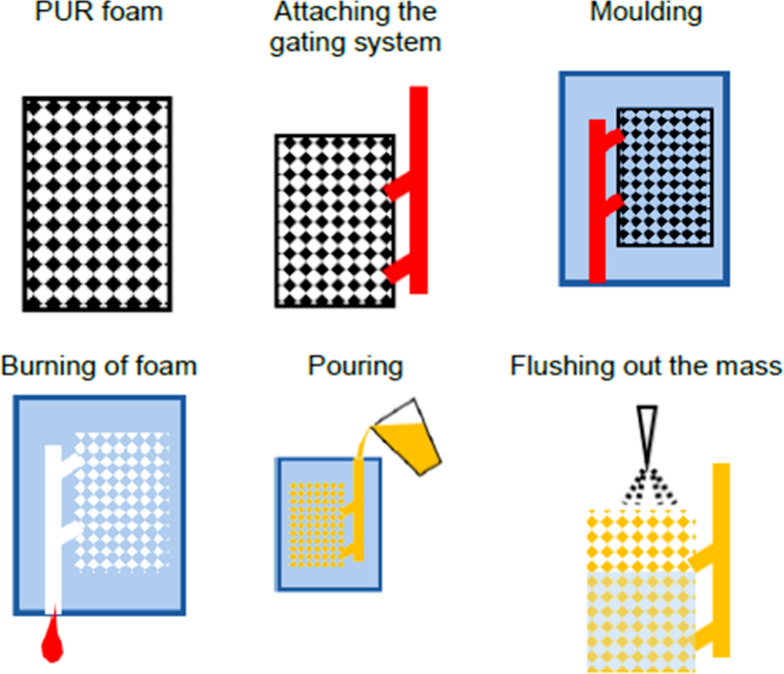
Diagram of foam production using an investment casting process.107
ERG Aerospace Corporation, Oakland, CA, (USA) is also using this method to fabricate metallic foam, and their product name is registered under the trade name “Duocel.” They produce different varieties of metallic foams such as copper, aluminum, brass, inconel, nickel, steel, tin, and zinc.105 Densities range from 3 to 12%, with varying grades in pores per inch. Homogeneous pore sizes range from 1/2 mm to 5 mm, and porosities range from 80%–97%.9,36,64 Mayser GmbH (Dresden, Germany) utilizes an identical method, but with an extra wax coating on the polymeric foam to increase stiffness.106 Then, drying at 350 °C removes wax and polymer, producing large, regular pores in metallic sponges with 10 mm diameter.36
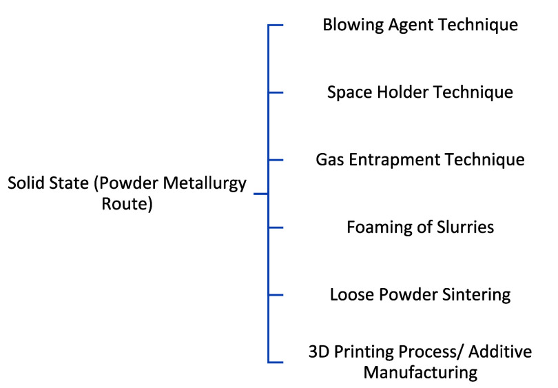
2.2. Solid State (Powder Metallurgy Route)
In contrast to the liquid melt route, another method is also used to fabricate the metallic foam. This method was patented in the late 1950s.75 The method involves processing the metal in solid form to produce metallic foam. The primary raw material employed in this process is a metallic powder, which maintains its solid state throughout the entirety of the procedure. Utilizing sintering and solid-state operations, metallic foam with an open cell morphology is achieved. The size and shape of the initial powder are vital for the resulting structure. When the system is in a liquid state, surface tension tends to create closed pores. In contrast, sintered porous products have an open structure, forming isolated spherical particles connected by sintered necks. This methodology is particularly well-suited for reactive metals characterized by high melting points. Additionally, the initial size and shape of the powder play a crucial role in influencing the ultimate morphology of the resulting product.36,45,46 The subclassification of this method is shown in Figure 10.
Figure 10.
Subclassification of metallic foam production techniques by the liquid state route.
2.2.1. Blowing Agent Technique
The metallic foam fabrication technique was invented and patented48 in the late 1950s, which involves adding of blowing agent directly into molten metal, but in the 1990s German scientists devised and patented108−110 a new method to fabricate metallic foam using a solid-state route. Similar to the introduction of gas-releasing agents into liquids, there are processes for creating foams by first producing a nearly dense precursor. This precursor can be heated later to induce foaming. During this treatment, the blowing agent undergoes decomposition, generating gas that facilitates the foam fabrication process. The primary technological challenge is ensuring the even distribution of the gas release agent within the preform without premature decomposition, specifically avoiding elevated temperatures before the foaming stage.
This process is also named the Fraunhofer process as it was invented at the Fraunhofer Institute in Bremen, Germany. The production process begins with the blending of raw metal powders with the appropriate foaming agents. After homogeneous mixing of these powders, they are subjected to compaction to get a dense semifinished product called the “precursor.” The most common compaction methods are uniaxial compression, rod extrusion, and powder rolling. To produce a high-quality foam, the blowing agent must be carefully inserted into the metal matrix without any significant residual porosity.30,31,111 The final step involves heat treatment, where the metal matrix precursor is heated to a temperature lower than its melting point but higher than the melting temperature of the blowing agent, which causes the blowing agent to decompose, resulting in the release of a large amount of gas, which causes expansion in the precursor and produces a close cell morphology structure diameter ranging from 1 mm to 5 mm.12,33,64,112 Expansion of the metal matrix takes a few seconds to several minutes, which mainly depends on the size of the precursor and furnace temperature.4,113,114 Hydrides like TiH2 are commonly used as blowing agents due to low melting points. Researchers have also suggested that carbonates can be replaced with hydrides and are less expensive.3,48 The list of blowing agents used in recent years is provided in Table 2 as mentioned in section 2.1.2. Figure 11 illustrates the schematic of foam production using the blowing agent method (the powder metallurgy route). Equations 1 and 2 represent the general decomposition chemical reaction equations of hydrides and carbonates respectively:
| 1 |
(hydrogen gas used as blowing gas in metallic foam fabrication).66
| 2 |
(CO2 gas used as blowing gas in metallic foam fabrication).68,69
Figure 11.
Schematic of foam production using the blowing agent method by the powder metallurgy route.9
Researchers have classified hydrides into three categories because of the nature of hydrogen bonds provided in Table 4.67,115 Many German and Austrian companies like Schunk (Gießen), Karmann (Osnabrück), Applied Light-weight Materials ALM (Saarbrücken), Honsel (Meschede), Alulight (Ranshofen), and Neuman Alufoam (Marktl) are now using this method to produce metallic foam at small scale commercial facilities.4,30
Table 4. Classification of Hydrides67,115.
| hydride type | hydrogen bond nature | common example |
|---|---|---|
| Covalent or volatile | Nonpolar electron sharing type, low melting point, absence of strong intermolecular forces | Aluminum, tin, boron, and germanium hydrides |
| Ionic or Saline | Presence of strong electrostatic forces, highly polar, high melting point | MgH2, CaH2, and SrH2 |
| Metallic | High thermal conductivity and electrical resistivity, portable sources of hydrogen | Titanium, thorium, and zirconium hydrides |
2.2.2. Space Holder Technique
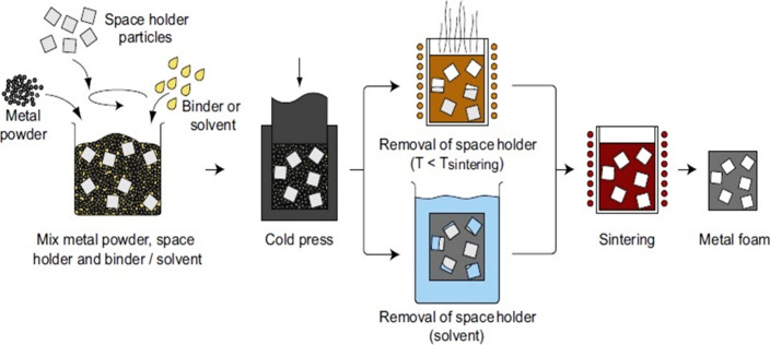
As articulated in section 2.1.4, the methodology for creating a porous metallic sponge encompasses the infusion of liquid metal into a mold featuring space-holding materials such as wire mesh, salt beads, hollow spheres, ceramics, and polymers. Noteworthy within the realm of patented techniques is a method dating back to 1962, wherein the metal powder is employed with space holders to yield metallic foam. This research underscores the evolution and application of innovative strategies in the fabrication of metallic structures with tailored porosity.116 The manufacturing technique for cellular metals begins with the mixing of a metal powder, space holder particles, and binders in one container. In the following step, these mixed particles are subjected to compaction, which is either axial or isostatic to form a dense two-phase precursor.9,31,45,61,117,118 The next step involves removing the space holder material, which is based on the space holder material selection in the previous step; there are two different processes: either the space holder is removed by thermal degradation or by dissolution. In the thermal degradation method, space holders have low melting points; e.g., PMMA, carbamide, or Mg grains are commonly used, and they degrade below the sintering temperature of the metal matrix after degradation of the space holder, and the metal matrix precursor is finally subjected to a sintering step to achieve densified metallic foam. while in the dissolution method the space holder usually has a higher melting point (e.g., NaCl or NaAlO2) than the metal matrix, and here the first metal matrix precursor is subjected to a sintering step, and then the space holder is removed by washing or dissolution to get metallic foam.45,84,119−121 A list of commonly used space holder materials is provided in Table 3 in section 2.1.4. Figure 12 illustrates the schematic of the space holder method for fabrication of metallic foam by the powder metallurgy route.
Figure 12.
Illustrates the schematic of the space holder method for fabrication of metallic foam by the powder metallurgy route.9
Space holder size, shape, volume fraction, and process parameters, such as compaction pressure and sintering temperature, affect the foam structure. Morphology is controlled by metal/space holder volume fraction, typically ranging from 50% to 85%. Above 85%, a continuous structure is difficult, and below 50%, removal of the space holder is difficult.38,84,122
2.2.3. Gas Entrapment Technique
As highlighted in the previous section, metallic foam is conventionally crafted through either melting or the introduction of a blowing agent. However, the method under scrutiny in this study diverges from these standard techniques. It is particularly well-suited for metals with heightened reactivity and elevated melting points. Originating from a patented process devised by Kearns in the late 1980s, this method unfolds in a sequence involving powder filling, inert gas backfills, hot isostatic pressing, gas entrapment, and carefully orchestrated heat treatment. This sophisticated approach represents a distinctive and intricate pathway in the realm of metallic foam production, underscoring its potential for diverse applications across both research and industrial domains.45,46,123Figure 13 illustrates a schematic of foam production using the gas entrapment method. Later, in the aviation industry, Boeing (USA) also employed this technology commercially to create titanium foam for aircraft panels, which Martin patented in the late 1990s.124 It begins with filling the designed shell with metal powder, and then in the next stage air is removed from the shell followed by the backfill of compatible inert gas. Inert gases are used due to their poor solubility in metals,122 typically argon gas at 3–5 atm pressure.125 After that, the shell is sealed and subjected to hot isostatic pressing at elevated temperatures and pressures, resulting in uniformity, and increased internal pressure of 10–16 MPa due to argon gas entrapment, which occupies only <2% of the total volume.64,111,122 The final step involves heat treatment, where the shell is annealed for 6–24 h at a temperature greater than 0.6 times the metal’s melting point.45,122,125 Annealing softens the material and causes entrapped argon gas to expand, lowering internal pressure until equilibrium pressure and strength are obtained.33,45,46,125,126 With this method, Boeing was able to achieve a porous structure with 20–40% unconnected porosity and pore diameters ranging from 10 to 100 μm. Research also claims that with this technique achieving more than 50% porosity is incredibly challenging.45,64,127
Figure 13.
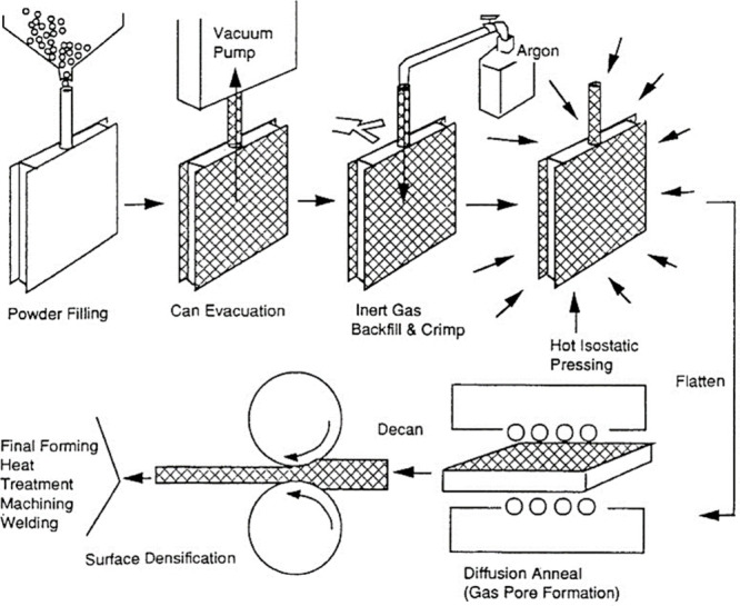
Diagram of the gas entrapment technique for producing metallic foam.45
2.2.4. Foaming of Slurries
A slurry is a thin mixture of insoluble particles in liquid. Slurry processing, a well-established technique in ceramics, faces unique challenges when applied to metal powders due to their larger size and higher density. Formulating stable metal powder slurries involves aqueous systems with added suspending agents and dispersants and adjustments for surface tension, pH, or gelation facilitation. Metallic foams can be produced through slurry, consisting of metal powder, solvent, and binder.128 The technique is further subdivided into three groups, which are listed below:84
-
(i)
Foaming by a blowing agent
-
(ii)
Foaming by a sponge replication method
-
(iii)
Foaming by mechanical whisking
2.2.4.1. Foaming by Blowing Agent
Metallic foams can be synthesized via the formulation of a slurry consisting of metal powders, blowing agents, and reactive additives. The process involves the meticulous blending of a fine metal powder with additives and blowing agents to achieve a homogeneous metallic slurry. Subsequently, this well-mixed slurry is introduced into a mold and subjected to elevated temperatures. The application of elevated temperatures induces a state of viscosity in the slurry, leading to expansion facilitated by gas generated during the decomposition of the blowing agent. This methodology aligns with established research principles to produce metallic foams, displaying its efficacy in controlled foam formation through a precisely orchestrated sequence of mixing and thermal treatment. Orthophosphoric acid with aluminum hydroxide or hydrochloric acid is used as a blowing agent. The metal-acid reaction produces hydrogen gas, which causes expansion in the slurry.84,129 To get high-quality metallic foam, adequate stabilizing measurements should be taken during the drying of slurries, and then, in the following stage, this dried slurry is subjected a sintering process to strengthen interconnected metallic foam. With this method, porosity up to 60% can be achieved.45,111,130
2.2.4.2. Foaming by the Sponge Replication Method
Introducing an innovative approach for the fabrication of porous metallic foam, distinct from the blowing agent technique, involves a straightforward amalgamation of a metal powder and binders with distilled water to form metal slurries. In this research approach, porous metals are crafted through a replication method utilizing an open-cell polyurethane (PU) foam or sponge as a template. This innovative process offers a unique perspective in the realm of metallic foam synthesis.131 The sponge replication method uses a polyurethane sponge as a negative replicate to create a metallic sponge structure.45,46,61,84 Polyurethane foam is then coated with metallic slurry by using a spraying or dipping technique, followed by removing the excess slurry through squeezing. Repeated immersion and squeezing ensured complete coverage of PU templates with the metallic slurry. After that, this coated template is left to dry for 24 h.84,131 In the next stage dried template is placed in a furnace for thermal degradation and removal of polyurethane foam, resulting in a weak metal structure, and then finally it is subjected to the sintering stage to obtain metallic foam.132−134 This method produces ultralight materials with porosity up to 90%–95% but faces challenges like viscosity, pH, binder, particle size, and shape.64,84
2.2.4.3. Foaming by Mechanical Whisking
The technique of producing foams from ceramic slurries, analogous to whisking cream, has been extended to metal systems. Inspired by the term “whisking”, signifying the blending of two ingredients, this method involves the addition of a surfactant to stabilize air bubbles introduced during whisking in metal powder slurries. The process begins with the preparation of a metallic slurry, achieved by blending metal powder, binder, and surfactant in distilled water. Surfactants reduce the interfacial tension between metallic slurry and air, so through proper aeration and then continuous whisking of metallic slurry, a foam is formed, which is poured into the mold. The slurry system should be gel by heating, gel by cooling, or polymerization, which helps to maintain the foam structure. The next step is drying of the foam structure, and then finally it is subjected to sintering to get a densified metallic matrix.84
2.2.5. Loose Powder Sintering
This is another intriguing technique recognized as a loose pack, pressure loss, or gravity sintering; this method employs metal powder in its loose state, foregoing prior compaction or precursor forms. Distinguished by its simplicity, cost-effectiveness, and ease of implementation, this technique is well-suited for a variety of metals, particularly those with elevated melting points such as titanium, superalloys, bronze, and steel. Its versatility renders it a compelling subject for exploration and application within diverse research contexts.45,111,135,136 The process begins with creating a mold, which serves as a negative replica of the desired structure, and then placing metal powder inside the mold under vibration to ensure thorough filling.12 In the last step, this mold is placed in a furnace for sintering under argon gas to obtain a porous structure. Certain measurements should be executed during the sintering process to avoid the formation of an oxidation layer on metal powder, which causes sintering complications.137 The strength of the porous materials obtained from this method is significantly lower than that of metallic foam obtained from other methods. The method achieves a porosity ranging from 20% to 50%, influenced by the size and shape of the metal powder as well as vibration speed.45,84
2.2.6. 3D Printing Process/Additive Manufacturing
The exponential progress in computer technology, artificial intelligence, and prototyping has wielded substantial influence across pivotal industries, encompassing aerospace, military, medical, industrial manufacturing, automotive, and space. Within this research context, our focus revolves around the utilization of a specialized technique for the fabrication of intricate metallic components, catering to the diverse requirements of these industries.138 In the realm of advanced manufacturing, this methodology harnesses computer-aided design (CAD) software to model intricate structures. Subsequently, employing computer-aided manufacturing (CAM), the technique enables the construction of components and objects with exceptional accuracy and precision.139 The product design diagram is uploaded to a system, where a machine begins manufacturing the part layer by layer. The process begins with a deposition of a metallic powder layer on a bed, and then, a highly directional heat source based on selective laser melting (SLM) and electron beam melting (EBM) is introduced to melt the powder according to the design. The next stage involves depositing a second layer of metallic powder on the first layer; by employing a substantial number of iterated layers, a three-dimensional component can be systematically generated as per CAD. The final stage involves the removal of any remaining unmelted powder, which holds the potential for recycling in subsequent processing. Following the 3D manufacturing process, the produced product undergoes a drying stage, and then, the foam metal product is subsequently sintered under vacuum conditions to achieve the desired structural integrity. This method demonstrates notable adaptability in the production of components characterized by intricate geometries, encompassing structures such as regular lattice materials. By employing this manufacturing technique, we can fabricate components with a minimum size of 500 μm.9,38,61,64,84Figure 14 illustrates the schematic of the additive layer manufacturing process.
Figure 14.
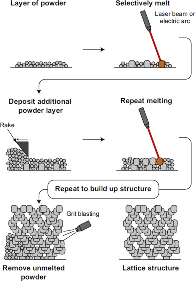
Schematic diagram of the additive layer manufacturing process.9
2.3. Metal Vapor
2.3.1. Metal Vapor Deposition
This intriguing technique is employed to produce metallic foam, commencing with the choice of a robust precursor structure, commonly polyurethane (PU), to determine the ultimate shape of the metallic foam.45 The process entails the generation of metal vapor through the heating of metal within a vacuum chamber, followed by condensation onto a polymeric substrate. Subsequent heat treatment facilitates the removal of the polymer, and the material undergoes sintering in a furnace, ultimately yielding the desired metallic foam formation.12,46,61,111 This process can be achieved through chemical vacuum deposition (CVD) or physical vapor deposition (PVD). CVD involves the thermal decomposition of metal carbonyl into gas which is further condensed on the polymeric substrate to produce metallic foam,140−143 Inco Limited (Toronto, Ontario, Canada) used this technique to produce commercial nickel metallic foam under the trade name of “Inco foam”. Figure 15 illustrates a schematic of the CVD process to produce Inco foam. PVD techniques are like CVD but differ in that the material being deposited is in solid form; it may be done through processes like metal spray deposition, thermal evaporation, reactive sputtering, and arc-vapor deposition to manufacture metal foams.144−147 In 1991, Vapor Technologies, Inc. patented a method for fabricating metallic foam using the arc-vapor deposition technique.148 The thickness of a coated film on a polymeric sponge significantly depends on the density of vapors and the exposure time of vapors on the substrate.45
Figure 15.
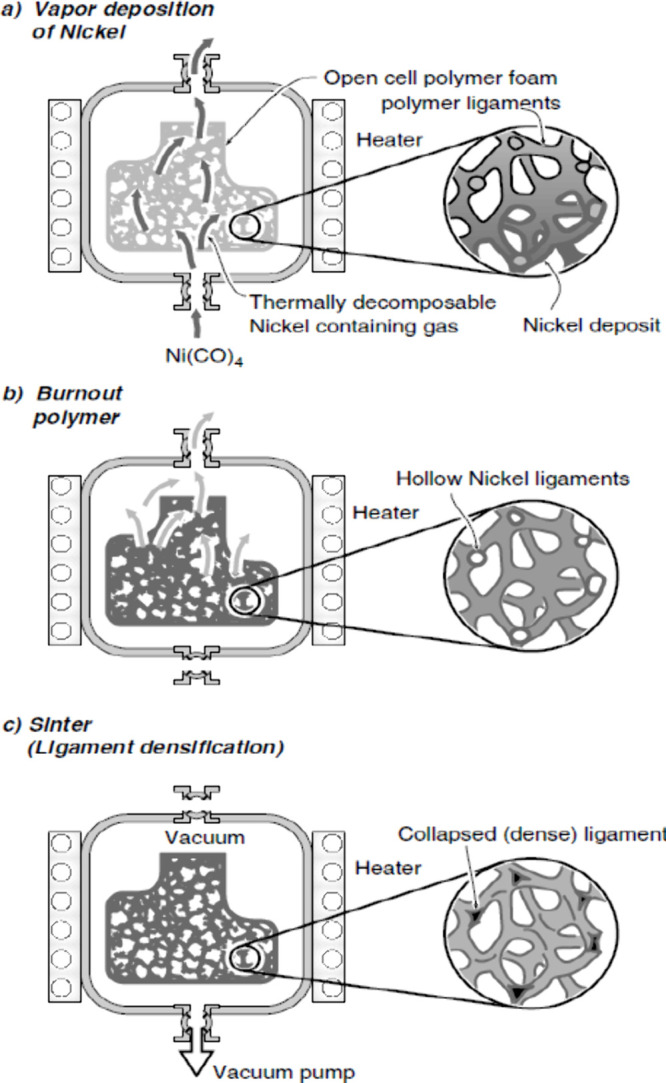
(a–c) Schematic of the CVD process to produce Inco foam.149
2.4. Metal Ion Solution
2.4.1. Electrochemical Deposition
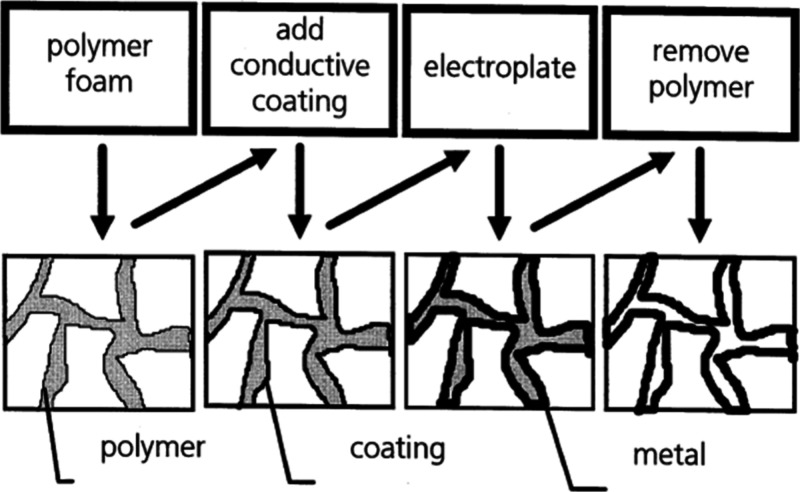
This technique operates on principles akin to vapor deposition and investment casting elucidated in sections 2.3.1 and 2.1.5 respectively. In this process, the initial sponge shape plays a crucial role in defining the ultimate structure of the metallic foam. It is noteworthy that, in electrochemical deposition, the resulting framework is hollow, in contrast to the solid framework characteristic of investment casting.38Figure 16 illustrates the schematic of the electrochemical technique for the production of metallic foam. The technique begins with the polymeric foam selection. The electrochemical technique involves the dissolution of an anode electrode and then the deposition of this metal on a cathode electrode. The parent metal will be used as the anode for fabricating metallic foam, while the cathode will be a polymeric foam for depositing it. The electrochemical technique requires both the anode and cathode to be conductive. To convert nonconductive polymeric foam into electrically conductive, it can be dipped into an electroless plating solution or by coating a thin conductive layer through cathodic sputtering or metal vaporization.46,145,150 In the next step, electroplating is used to create metallic deposition on the polymeric foam, which is then removed through heat treatment. The metal foam is then subjected to sintering to obtain the final porous structure.45,61 Retimet (Dunlop), Celmet (Sumitomo Electric), and Recemat (SEAC, The Netherlands) are commercially available foams.111 Metallic foam fabricated through this technique is mostly in nanoporous structures, and in the modern age they have impacted many industrial sectors like aerospace, biomedical automotive, and marine engineering due to their electrical impedance and large surface area property.64,151,152
Figure 16.
Schematic of electrochemical technique for production of metallic foam (adapted from ref (45); copyright 2001 Elsevier).
Table 5 represents different methods for the fabrication of metallic foams as well as describes the cell structure of metallic foams. It will be either open, closed, or lotus type depending on fabrication methods chosen during manufacturing.
Table 5. Different Methods for Fabrication of Metallic Foam.
| production route | metallic foam fabrication method | cell type | porosity percentage | mechanical properties studied | reference |
|---|---|---|---|---|---|
| Liquid metallurgy route | Melt gas injection | closed | 75–97 | Compressive, energy absorption, morphological investigation | (55, 58−60) |
| Blowing agent | closed | 68–85 | Compressive stress and strain at a dynamic strain rate | (42, 65, 71) | |
| Dissolved gases (solid gas eutectic solidification-GASAR) | lotus | 8.5–60 | Micro Vickers hardness | (73, 77−79) | |
| Space holder (infiltration method) | open | 54–85 | Energy absorption, compressive strength, young modulus | (83,91, 99) | |
| Foam replication (investment casting) | open | 80–97 | Sound absorption, strain hardening, energy absorption, yield strength | (100, 103, 104) | |
| Powder metallurgy route | Blowing agent | closed | 15.1–44.5 | Compressive strength, elastic modulus, relative density | (110, 112) |
| Space holder | open | 40–92 | Compressive yield strength and modulus of elasticity | (116, 120, 121) | |
| Gas entrapment technique | Closed/partially open | <50 | Creep expansion via eddy currents | (124, 126, 127) | |
| Foaming of slurries | Closed/partially open | 60–91 | Tensile & compression test, thermal conductivity | (130, 131, 134) | |
| Loose powder sintering | Open | 30–37.5 | Young Modulus, yield strength | (137) | |
| Additive manufacturing | Open | 49–74 | Compressive strength, controllable morphology | (139) | |
| Deposition route | Metal vapor | Open | 70–98 | Young modulus, shear modulus, energy absorption, thermal conductivity | (141, 145) |
| Electrochemical deposition route | Metal ion solution | Open | 92–95 | Specific capacitance value, Impedance | (45, 150−153) |
Similarly, Table 6 provides a comprehensive analysis of the advantages, disadvantages, and challenges encountered in mass production of various metal foam processing technologies.
Table 6. Advantages, Disadvantages, and Challenges of Mass Production of Various Methods for Fabricating Metallic Foam.
| Production route | Metallic foam fabrication method | advantages | Disadvantages & challenges in mass production | reference |
|---|---|---|---|---|
| Liquid metallurgy route | Melt gas injection | Large volume production, low-density metallic foam | Foam stabilization, imperfections, and inconsistencies, controlling the foam quality, and optimizing processing parameters | (6, 62, 63) |
| Blowing agent | formation of foam in several types of alloys, including lightweight alloys and low-density metallic foam | Inflated cost of hydride blowing agent, controlling porosity and cell size is challenging, not suitable for creating intricate structures or shapes, optimizing processing parameters. | (4, 33) | |
| Dissolved gases (solid gas eutectic solidification-GASAR) | Good for a variety of steels, cobalt, chromium, molybdenum, and even ceramics | GASAR metallic foams may exhibit unsatisfactory homogeneity sometimes; pores size depends upon cooling rate; the process requires complicated equipment and turns out to be expensive; limited to metal which forms eutectic systems with hydrogen gas | (9, 33, 45) | |
| Space holder (infiltration method) | Cost-effective with an affordable space holder, particularly effective for close foam-to-dense metal bonding in parts like sandwich beams, enabling precise control of pore size, and distribution via space holder grain size | A challenging process demanding extreme caution to fill a mold with molten metal | (9, 12, 45) | |
| Foam replication (investment casting) | Gives flexibility in terms of the choice of metal; the process is simpler to implement, resulting in highly porous and high-quality foam. | The drawback of this method is the complete filing of mold, directional solidification, and removal of mold without damaging fine structure due to the high percentage of porosities. | (33, 45, 62) | |
| Powder metallurgy route | Blowing agent | The manufacturing process excels in producing high-quality foams, fabricating intricate parts, accommodating a variety of metals and alloys, and easily preparing sandwich panels. | Expensive method due to its two-step compacting process, controlling foaming duration for high-quality foam | (9, 33, 45, 62, 110) |
| Space holder | Controlled pore morphology, higher compressive strength, low cost, and easy to handle | Removal of complete space holder material, nonuniform properties, and Limited porosity. | (6, 9, 34, 154) | |
| Gas entrapment technique | Mainly used to create porous lightweight titanium structures | Mostly limited to titanium and its alloy, The process requires complex equipment and turns out to be expensive. | (111, 122) | |
| Foaming of slurries | The ability to produce ultralight materials with high porosity is a potential advantage. | Insufficient strength issues and potential foamed material cracks may arise. | (45, 64, 84) | |
| Loose powder sintering | Fine porosity can be created intentionally during the manufacturing process. | Commonly used for bronze; products have comparatively low strengths. | (45) | |
| Additive Manufacturing | This technique offers stately design flexibility, allowing for small and precise structures with complex internal shapes, reduced material waste, cost-effectiveness, and rare shape-making ability. | Inflated cost of equipment and materials; skilled operators required, limited range of material for foam fabrication | (9, 84, 139) | |
| Deposition route | Metal Vapor | Low density, high stiffness with good energy absorption properties, customizable design flexibility | Limited to small-scale production due to high processing costs | (9, 33, 62) |
| electrochemical deposition route | Metal ion solution | Used to produce nanoporous structure; foam possesses good electrical impedance and a large surface area. | limited to small-scale manufacturing because of the expensive processes involved | (9, 33, 62, 152) |
3. Conclusion
This review explores diverse ways to make metallic foams, benefiting from recent technological advancements that offer a wide range of production options for various metals and alloys. These advanced methods make it possible to achieve high porosities of up to 98%. This study shows that with the liquid metallurgy route, it is easy to produce metallic foam, and it is very cost-effective. On the other hand, the powder metallurgy method is difficult compared to the liquid metallurgy route due to manufacturing processes. This method is also more expensive than the liquid metallurgy route because of different variables like pressure and making of precursor. The powder metallurgy route gives uniform morphology, while the liquid metallurgy route is a contrast to that. As technology and research advance, ongoing innovations in metallic foam manufacturing are driven by scientists and researchers striving to enhance the effectiveness and efficiency of fabrication methods, aiming to reduce the overall cost of metallic foams. Notably, additive manufacturing, an innovative technology, stands out as the latest method capable of precision manufacturing intricate shapes. While electrolytic methods can produce nanoporous metallic foams, their current expense poses a challenge, underscoring the continuous pursuit of cost-effective alternatives in the field. Metallic foams have a very wide range of industrial applications such as aerospace, automotive, biomedical, acoustic, filtration, heat exchange, structure, impact absorption, and radiation shielding. Current developments focus on cost reduction through cheaper materials, streamlined processing, and reduced production scrap, aiming to achieve industrial mass-market applications and expand the use of cellular metallic materials.
Acknowledgments
The authors extend their appreciation to the Center of Excellence for Research in Engineering Material (CEREM) and the Department of Mechanical Engineering at King Saud University (KSU), Riyadh, Saudi Arabia, for their valuable support in conducting this work.
The authors declare no competing financial interest.
References
- Banhart J.Metal foams-from fundamental research to applications Front. Des.Mater. 2007, 279. [Google Scholar]
- Ashby M. F.; Lu T. J. The structure and acoustic properties of aluminum foams by gas injection method. Sci. China Ser. B: Chem. 2003, 46, 521–532. [Google Scholar]
- Lefebvre L.-P.; Banhart J.; Dunand D. Porous Metals and Metallic Foams: Current Status and Recent Developments. Adv. Eng. Mater. 2008, 10, 775–787. 10.1002/adem.200800241. [DOI] [Google Scholar]
- Banhart J. Manufacturing routes for metallic foams. JOM 2000, 52 (12), 22–27. 10.1007/s11837-000-0062-8. [DOI] [Google Scholar]
- Kumar G. S. V.; Heim K.; Garcia-Moreno F.; Banhart J.; Kennedy A. R. Foaming of aluminum alloys derived from scrap. Adv. Eng. Mater. 2013, 15 (3), 129–133. 10.1002/adem.201200122. [DOI] [Google Scholar]
- Parveez B.; Jamal N. A.; Anuar H.; Ahmad Y.; Aabid A.; Baig M. Microstructure and mechanical properties of metal foams fabricated via melt foaming and powder metallurgy technique: A review. Materials 2022, 15 (15), 5302. 10.3390/ma15155302. [DOI] [PMC free article] [PubMed] [Google Scholar]
- Li J. W.; Shan C. F.; Teng Y. L.; Gai Z. C. Development of Low Cost Lightweight Aluminum Foam for Railway Transportation. IOP Conf Ser. Mater. Sci. Eng. 2019, 649 (1), 012002. 10.1088/1757-899X/649/1/012002. [DOI] [Google Scholar]
- De Meller M. A.Produit métallique pour l’obtention d’objets laminés, moulés ou autres, et procédés pour sa fabrication. French Patent, FR615147A, 1925.
- Goodall R.; Mortensen A.. 24 - Porous Metals. In Physical Metallurgy, Fifth ed.; Laughlin D. E., Hono K., Eds.; Elsevier: Oxford, 2014; pp 2399–2595. 10.1016/B978-0-444-53770-6.00024-1. [DOI] [Google Scholar]
- Chen S.; Bourham M.; Rabiei A. Applications of Open-cell and Closed-cell Metal Foams for Radiation Shielding. Procedia Materials Science 2014, 4, 293–298. 10.1016/j.mspro.2014.07.560. [DOI] [Google Scholar]
- Dukhan N.Metal Foams: Fundamentals and Applications; DEStech Publications, Inc., 2012. [Google Scholar]
- Ashby M. F.; Lu T. Metal foams: A survey. Sci. China B Chem. 2003, 46 (6), 521–532. 10.1360/02yb0203. [DOI] [Google Scholar]
- Bisht A.; Patel V. K.; Gangil B.. Future of Metal Foam Materials in Automotive Industry. In Automotive Tribology; Katiyar J. K., Bhattacharya S., Patel V. K.; Kumar V., Eds.; Springer: Singapore, 2019; pp 51–63. 10.1007/978-981-15-0434-1_4. [DOI] [Google Scholar]
- Yu X.; Lu Z.; Zhai W. Enhancing the flow resistance and sound absorption of open-cell metallic foams by creating partially-open windows. Acta Mater. 2021, 206, 116666. 10.1016/j.actamat.2021.116666. [DOI] [Google Scholar]
- Opiela K. C.; Zieliński T. G.; Dvorák T.; Kúdela S. Jr. Perforated closed-cell aluminium foam for acoustic absorption. Applied Acoustics 2021, 174, 107706. 10.1016/j.apacoust.2020.107706. [DOI] [Google Scholar]
- Arjunan A.; Baroutaji A.; Praveen A. S.; Olabi A. G.; Wang C. J.. Acoustic performance of metallic foams. In Reference Module in Materials Science and Materials Engineering; Elsevier, 2019, 10.1016/B978-0-12-803581-8.11561-9. [DOI] [Google Scholar]
- Nawaz K.; Bock J.; Jacobi A. M. Thermal-hydraulic performance of metal foam heat exchangers under dry operating conditions. Appl. Therm Eng. 2017, 119, 222–232. 10.1016/j.applthermaleng.2017.03.056. [DOI] [Google Scholar]
- Boomsma K.; Poulikakos D.; Zwick F. Metal foams as compact high performance heat exchangers. Mech. Mater. 2003, 35 (12), 1161–1176. 10.1016/j.mechmat.2003.02.001. [DOI] [Google Scholar]
- Hassan A. M.; Alwan A. A.; Hamzah H. K. Metallic foam with cross flow heat exchanger: A review of parameters, performance, and challenges. Heat Transfer 2023, 52 (3), 2618–2650. 10.1002/htj.22798. [DOI] [Google Scholar]
- Hooman K.; Chumpia A.; Jadhav P.; Rudolph V.. Metal foam heat exchanger for dry cooling. Final Report for ANLEC Project, 2013; pp 5–710
- ERG , Duocel® Foam Heat Exchangers, Product information of Duocel® Foam Heat Exchangers and URL (https://ergaerospace.com/phase-change-heat-exchangers/).
- Matassi F.; Botti A.; Sirleo L.; Carulli C.; Innocenti M. Porous metal for orthopedics implants. Clinical Cases in Mineral and Bone Metabolism 2013, 10 (2), 111. [PMC free article] [PubMed] [Google Scholar]
- Munir K. S.; Li Y.; Wen C.. 1 - Metallic scaffolds manufactured by selective laser melting for biomedical applications. In Metallic Foam Bone,; Wen C., Ed.; Woodhead Publishing, 2017; pp 1–23. 10.1016/B978-0-08-101289-5.00001-9. [DOI] [Google Scholar]
- Beköz Üllen N.; Karabulut G.. The place of metal foams in biomaterial applications. In Conference: 2nd International Eurasian Conference on Science, Engineering and Technology (EurasianSciEnTech 2020), 2020.
- Vahidgolpayegani A.; Wen C.; Hodgson P.; Li Y.. 2 - Production methods and characterization of porous Mg and Mg alloys for biomedical applications. In Metallic Foam Bone; Wen C., Ed.; Woodhead Publishing, 2017; pp 25–82. 10.1016/B978-0-08-101289-5.00002-0. [DOI] [Google Scholar]
- Guden M.; Celik E.; Cetiner S.; Aydin A.. Metals Foams for Biomedical Applications: Processing and Mechanical Properties. In Biomaterials; Hasirci N.; Hasirci V., Eds.; Springer U.S.: Boston, MA, 2004; pp 257–266. [DOI] [PubMed] [Google Scholar]
- Malloy J.; Quintana A.; Jensen C. J.; Liu K. Efficient and Robust Metallic Nanowire Foams for Deep Submicrometer Particulate Filtration. Nano Lett. 2021, 21 (7), 2968–2974. 10.1021/acs.nanolett.1c00050. [DOI] [PubMed] [Google Scholar]
- Liu K. U.S. Patent, Nanoporous metal foam gas filters. US20200086257A1, March 19, 2020.
- Fiedler W. S.Method of making metal foam bodies. US3087807A, Oct. 26, 1965.
- Babcsán N.; Banhart J.; Leitlmeier D. Metal foams–manufacture and physics of foaming. Proc. Int. Conference Adv. Metallic Mater. 2003, 5–15. [Google Scholar]
- Surace R.; De Filippis L.. Investigation and Comparison of Aluminium Foams Manufactured by Different Techniques. In Advanced Knowledge Application in Practice; InTech, 2010. 10.5772/10353. [DOI] [Google Scholar]
- Ikeda T.; Nakajima H.; Aoki T. Fabrication of lotus-type porous stainless steel by continuous zone melting technique and mechanical property. Metallurgical and Materials Transactions A 2005, 36 (1), 77–86. 10.1007/s11661-005-0140-1. [DOI] [Google Scholar]
- Kulshreshtha A.; Dhakad S. K. Preparation of metal foam by different methods: A review. Mater. Today Proc. 2020, 26, 1784–1790. 10.1016/j.matpr.2020.02.375. [DOI] [Google Scholar]
- Madgule M.; Sreenivasa C. G.; Borgaonkar A. V. Aluminium metal foam production methods, properties and applications- a review. Mater. Today Proc. 2023, 77, 673–679. 10.1016/j.matpr.2022.11.287. [DOI] [Google Scholar]
- Sunder Sharma S.; Yadav S.; Joshi A.; Goyal A.; Khatri R. Application of metallic foam in vehicle structure: A review,. Mater. Today Proc. 2022, 63, 347–353. 10.1016/j.matpr.2022.03.201. [DOI] [Google Scholar]
- García-Moreno F. Commercial Applications of Metal Foams: Their Properties and Production. Materials 2016, 9, 85. 10.3390/ma9020085. [DOI] [PMC free article] [PubMed] [Google Scholar]
- Fraunhofer B. L. D.Institute for Manufacturing Technology and Advanced Materials IFAM; Open Cell Metal Foams; https://www.ifam.fraunhofer.de/content/dam/ifam/en/documents/dd/Infobl%C3%A4tter/open_cell_metal_foams_fraunhofer_ifam_dresden.pdf.
- Wan T.; Liu Y.; Zhou C.; Chen X.; Li Y. Fabrication, properties, and applications of open-cell aluminum foams: A review. J. Mater. Sci. Technol. 2021, 62, 11–24. 10.1016/j.jmst.2020.05.039. [DOI] [Google Scholar]
- Jang W.-Y.; Kyriakides S.; Kraynik A. M. On the compressive strength of open-cell metal foams with Kelvin and random cell structures. Int. J. Solids Struct 2010, 47 (21), 2872–2883. 10.1016/j.ijsolstr.2010.06.014. [DOI] [Google Scholar]
- Elliott J. C. U.S. Patents. Method of producing metal foam. US2751289A, Jun. 19, 1956.
- Banhart J. Light-Metal Foams—History of Innovation and Technological Challenges. Adv. Eng. Mater. 2013, 15, 82. 10.1002/adem.201200217. [DOI] [Google Scholar]
- Miyoshi T.; Itoh M.; Akiyama S.; Kitahara A. Aluminum Foam, ‘Alporas’: The Production Process, Properties and Applications. MRS Online Proceedings Library 1998, 521 (1), 133–137. 10.1557/PROC-521-133. [DOI] [Google Scholar]
- Banhart J.; Ashby M.; Fleck N.. Metal foams and porous metal structures. Conference on Metal Foams and Porous Metal Structures; Verlag, MIT Publishing, 1999; p 16.
- Degischer H.; Kriszt B.. Handbook of Cellular Metals: Production, Processing, Applications; Hans-Peter Degischer H.-P., Kriszt B., Eds.; Wiley, 2002. [Google Scholar]
- Banhart J. Manufacture, characterisation, and application of cellular metals and metal foams. Prog. Mater. Sci. 2001, 46 (6), 559–632. 10.1016/S0079-6425(00)00002-5. [DOI] [Google Scholar]
- Tatt T. K. Review on Manufacturing of Metal Foams. ASM Sci. J. 2021, 16, 1–8. 10.32802/asmscj.2021.794. [DOI] [Google Scholar]
- Banhart J. Metal Foams: Production and Stability. Adv. Eng. Mater. 2006, 8, 781. 10.1002/adem.200600071. [DOI] [Google Scholar]
- Elliott J. C.Metal foam and method for making. Patent, US81955859A, May 09, 1961.
- Berry C. B., Jr.Foamed metal. U.S. Patent US3669654A, Jun. 13, 1972.
- Bjorksten J.; Rock E. J.. Method for foaming Metals. U.S. Patent US3707367A, Dec. 26, 1972.
- Niebylski L. M.; Jarema C. P.; Immethun P. A.. Metal foams and process therefor. U.S. Patent, 3794481, 1974, p 26.
- Jin I.; Kenny L. D.; Sang H.. Method of producing lightweight foamed metal. U.S. Patent US4973358A, Nov. 27, 1990.
- Thomas M.; Kenny L. D.. Production of particle-stabilized metal foams. PCT Patent WO, vol. 94, no. 017218, p 21, 1994.
- Ruch W.; Kirkevag B.. A process of manufacturing particle reinforced metal foam and product thereof. European Patent 0483,184,1994, 1990.
- Jin I.; Kenny L. D.; Sang H.. Stabilized metal foam body. U.S. Patent US5112697A, May 12, 1992.
- Cymat , Product Information of Aluminum foam by Cymat, https://www.cymat.com/industries-other-applications/.
- Hrdro Aluminum , Product Information of Aluminum metallic foam by Hrdro Aluminum, https://www.hydro.com/en/aluminium/.
- Wang N.; et al. Compressive performance and deformation mechanism of the dynamic gas injection aluminum foams. Mater. Charact 2019, 147, 11–20. 10.1016/j.matchar.2018.10.013. [DOI] [Google Scholar]
- Surace R.; De Filippis L. A. C.; Niini E.; Ludovico A. D.; Orkas J. Morphological Investigation of Foamed Aluminum Parts Produced by Melt Gas Injection. Adv. Mater. Sci. Eng. 2009, 2009, 506024. 10.1155/2009/506024. [DOI] [Google Scholar]
- Huiming Z.; Xiang C.; Xueliu F.; Yanxiang L.. Compressive properties of aluminum foams by gas injection method. China Foundry 2012, 9, (3), , 215. [Google Scholar]
- Singh S.; Bhatnagar N. A survey of fabrication and application of metallic foams (1925–2017). Journal of Porous Materials 2018, 25 (2), 537–554. 10.1007/s10934-017-0467-1. [DOI] [Google Scholar]
- Gergely V.; Degischer H. P.; Clyne T. W.. 3.30 - Recycling of MMCs and Production of Metallic Foams. In Comprehensive Composite Materials; Kelly A.; Zweben C., Eds.; Pergamon: Oxford, 2000; pp 797–820. 10.1016/B0-08-042993-9/00205-9. [DOI] [Google Scholar]
- Pamidi V.; Mukherjee M. Melt injection – A novel method to produce metal foams. Materialia (Oxf) 2018, 4, 500–509. 10.1016/j.mtla.2018.11.009. [DOI] [Google Scholar]
- Rajak D. K.; Gupta M.. Manufacturing Methods of Metal Foams. In An Insight Into Metal Based Foams: Processing, Properties and Applications,; Rajak D. K.; Gupta M., Eds., Springer Singapore: Singapore, 2020; pp 39–52. 10.1007/978-981-15-9069-6_3. [DOI] [Google Scholar]
- Rajak D. K.; Mahajan N. N.; Das S. Fabrication and investigation of influence of CaCO3 as foaming agent on Al-SiCp foam. Materials and Manufacturing Processes 2019, 34 (4), 379–384. 10.1080/10426914.2018.1532093. [DOI] [Google Scholar]
- Bisht A.; Gangil B.; Patel V. K.. Selection of blowing agent for metal foam production: A review. J. Metals Mater. Minerals 2020, 30, 10.55713/jmmm.v30i1.597. [DOI] [Google Scholar]
- Matijasevic-Lux B.Characterisation and Optimisation of Blowing Agent for Making Improved Metal Foams, 2006.
- Kevorkijan V.Low cost aluminium foams made by CaCO3 particulates. Association of Metallurgical Engineers of Serbia 2010, 16, (3), . [Google Scholar]
- Koizumi T.; Kido K.; Kita K.; Mikado K.; Gnyloskurenko S.; Nakamura T. Foaming Agents for Powder Metallurgy Production of Aluminum Foam. Mater. Trans 2011, 52 (4), 728–733. 10.2320/matertrans.M2010401. [DOI] [Google Scholar]
- Schwartz D. S.; Shih D. S.; Evans A. G.; Wadley H. N. G.. Porous and cellular materials for structural applications, Materials Research Society, Warrendale, PA (United States), 1998. [Online]. Available: https://www.osti.gov/biblio/361796.
- Mukai T.; Kanahashi H.; Miyoshi T.; Mabuchi M.; Nieh T. G.; Higashi K. Experimental study of energy absorption in a close-celled aluminum foam under dynamic loading. Scr Mater. 1999, 40 (8), 921–927. 10.1016/S1359-6462(99)00038-X. [DOI] [Google Scholar]
- Miyoshi T.; Itoh M.; Akiyama S.; Kitahara A. ALPORAS Aluminum Foam: Production Process, Properties, and Applications. Adv. Eng. Mater. 2000, 2 (4), 179–183. . [DOI] [Google Scholar]
- Shapovalov V. I.Method for manufacturing porous articles. U.S. Patent US5181549A, Jan. 26, 1993.
- Schwartz D. S.; Shih D. S.; Evans A. G.; Wadley H. N. G. Porous and cellular materials for structural applications. MRS Symp. Proc. 1998, 225. [Google Scholar]
- Allen B. C.; Mote M. W.; Sabroff A. M.. Method of making foamed metal. U.S. Patent US3087807A, Apr. 30, 1963.
- Boczkal G.; Janoska M.; Setman D.; Schafler E.; Dlugosz P.; Darlak P. Magnesium gasar as a potential monolithic hydrogen absorbent. Int. J. Hydrogen Energy 2021, 46 (24), 13106–13115. 10.1016/j.ijhydene.2021.01.166. [DOI] [Google Scholar]
- Hyun S.; Nakajima H. Fabrication of Lotus-Structured Porous Iron by Unidirectional Solidification under Nitrogen Gas. Adv. Eng. Mater. 2002, 4 (10), 741–744. . [DOI] [Google Scholar]
- Kashihara M.; Hyun S. K.; Yonetani H.; Kobi T.; Nakajima H. Fabrication of lotus-type porous carbon steel by unidirectional solidification in nitrogen atmosphere. Scr Mater. 2006, 54 (4), 509–512. 10.1016/j.scriptamat.2005.10.047. [DOI] [Google Scholar]
- Kashihara M.; Suzuki S.; Kawamura Y.; Kim S.-Y.; Yonetani H.; Nakajima H. Fabrication of Lotus-Type Porous Carbon Steel Slabs by Continuous Casting Technique in Nitrogen Atmosphere. Metallurgical and Materials Transactions A 2010, 41 (9), 2377–2382. 10.1007/s11661-010-0314-3. [DOI] [Google Scholar]
- Li W.; Xu K.; Li H.; Jia H.; Liu X.; Xie J. Energy Absorption and Deformation Mechanism of Lotus-type Porous Coppers in Perpendicular Direction. J. Mater. Sci. Technol. 2017, 33 (11), 1353–1361. 10.1016/j.jmst.2017.01.009. [DOI] [Google Scholar]
- Gibson L. J.; Ashby M. F.. Cellular Solids: Structure and Properties, 2nd ed.; Cambridge University Press: Cambridge, 1997. 10.1017/CBO9781139878326. [DOI] [Google Scholar]
- Wood J.; Banhart J.; Eifert H.. Metal Foams; MIT-Verlag: Bremen, Germany, 1997; p 31. [Google Scholar]
- Li C.; Wang Y.; Liu Z.; Zheng P.; Zhang Q.; Han B. Multifunctional Open-Cell Copper Foam with Sphere Pores by a Modified Sintering–Dissolution Process. Metals (Basel) 2023, 13 (4), 791. 10.3390/met13040791. [DOI] [Google Scholar]
- Kennedy A.Porous Metals and Metal Foams Made from Powders, In (InTech) Powder Metallurgy 2012. 10.5772/33060. [DOI] [Google Scholar]
- Jiang B.; Zhao N. Q.; Shi C. S.; Li J. J. Processing of open cell aluminum foams with tailored porous morphology. Scr Mater. 2005, 53 (6), 781–785. 10.1016/j.scriptamat.2005.04.055. [DOI] [Google Scholar]
- Wang S.; Yin Y.; Chen L.; Liu X.; Jia Q.; Zhang S. Controllable preparation of porous ZrB2–SiC ceramics via using KCl space holders. Ceram. Int. 2021, 47 (24), 33978–33987. 10.1016/j.ceramint.2021.08.305. [DOI] [Google Scholar]
- Sazegaran H. Investigation on Production Parameters of Steel Foam Manufactured Through Powder Metallurgical Space Holder Technique. Metals and Materials International 2021, 27 (9), 3371–3384. 10.1007/s12540-020-00659-z. [DOI] [Google Scholar]
- Tan K. T.; Muhamad N.; Muchtar A.; Sulong A. B.; Kok Y. S. Production of Porous Stainless Steel using the Space Holder Method. Sains Malays 2021, 50, 507–514. 10.17576/jsm-2021-5002-21. [DOI] [Google Scholar]
- Li D. S.; Zhang Y. P.; Ma X.; Zhang X. P. Space-holder engineered porous NiTi shape memory alloys with improved pore characteristics and mechanical properties. J. Alloys Compd. 2009, 474 (1), L1–L5. 10.1016/j.jallcom.2008.06.043. [DOI] [Google Scholar]
- Xiang C.; Zhang Y.; Li Z.; Zhang H.; Huang Y.; Tang H. Preparation and compressive behavior of porous titanium prepared by space holder sintering process. Procedia Eng. 2012, 27, 768–774. 10.1016/j.proeng.2011.12.518. [DOI] [Google Scholar]
- Wan T.; Liu Y.; Zhou C.; Ding X.; Chen X.; Li Y. Fabrication of high-porosity open-cell aluminum foam via high-temperature deformation of CaCl2 space-holders. Mater. Lett. 2021, 284, 129018. 10.1016/j.matlet.2020.129018. [DOI] [Google Scholar]
- Jiang G.; He G. A new approach to the fabrication of porous magnesium with well-controlled 3D pore structure for orthopedic applications. Materials Science and Engineering: C 2014, 43, 317–320. 10.1016/j.msec.2014.07.033. [DOI] [PubMed] [Google Scholar]
- Kwok P.; Oppenheimer S.; Dunand D. Porous Titanium by Electro-chemical Dissolution of Steel Space-holders. Adv. Eng. Mater. 2008, 10, 820–825. 10.1002/adem.200800072. [DOI] [Google Scholar]
- Ozer G.; Guler K. A.; Taslicukur Z. Cellular Aluminum Foam Metal Production With Space Holder Particles. Materialprufung 2010, 52, 379. 10.3139/120.110140. [DOI] [Google Scholar]
- Jamal N. Fabrication and Compressive Properties of Low to Medium Porosity Closed-Cell Porous Aluminum Using PMMA Space Holder Technique. Materials 2016, 9, 254. 10.3390/ma9040254. [DOI] [PMC free article] [PubMed] [Google Scholar]
- Tan P. P.; Mohamad H.; Anasyida A. S.. Properties of porous magnesium using polymethyl methacrylate (PMMA) as a space holder. In Journal of Physics: Conference Series; IOP Publishing, 2018; p 012063. [Google Scholar]
- Zhao Y. Y.; Fung T.; Zhang L. P.; Zhang F. L. Lost carbonate sintering process for manufacturing metal foams. Scr Mater. 2005, 52 (4), 295–298. 10.1016/j.scriptamat.2004.10.012. [DOI] [Google Scholar]
- Báez-Pimiento S.; Hernández-Rojas M. E.; Palomar-Pardavé M. E. Processing and Characterization of Open–Cell Aluminum Foams Obtained through Infiltration Processes. Procedia Materials Science 2015, 9, 54. 10.1016/j.mspro.2015.04.007. [DOI] [Google Scholar]
- Cheng M.; et al. A novel open-porous magnesium scaffold with controllable microstructures and properties for bone regeneration. Sci. Rep 2016, 6 (1), 24134. 10.1038/srep24134. [DOI] [PMC free article] [PubMed] [Google Scholar]
- Fraunhofer Institute for Manufacturing Technology and Advanced Materials IFAM , Open Porous Aluminum Foams and Metal-Polymer Hybrid Structures, 2017, Accessed: Aug. 05, 2023. [Online]. Available: https://www.ifam.fraunhofer.de/content/dam/ifam/en/documents/Shaping_Functional_Materials/powder_technology/offenporoese_schaeume_en_fraunhofer_ifam.pdf.
- Yosida Y.; Hayashi C.. Casting Science and Technology, 1990. [Google Scholar]
- Yamada Y. Processing of Cellular Magnesium Materials. Adv. Eng. Mater. 2000, 2 (4), 184–187. . [DOI] [Google Scholar]
- Wang X. F.; Wang X. F.; Wei X.; Han F. S.; Wang X. L. Sound absorption of open celled aluminium foam fabricated by investment casting method. Mater. Sci. Technol. 2011, 27 (4), 800–804. 10.1179/026708309X12506934374047. [DOI] [Google Scholar]
- Frömert J.; Lott T. G.; Matz A. M.; Jost N. Investment Casting and Mechanical Properties of Open-Cell Steel Foams. Adv. Eng. Mater. 2019, 21 (6), 1900396. 10.1002/adem.201900396. [DOI] [Google Scholar]
- O. C. (USA) ERG Aerospace Corporation , ERG Aerospace Corporation, Oakland, CA, (USA), Product information of Duocel and (http://www.ergaerospace.com).
- G. Mayser GmbH (Dresden, “Mayser GmbH (Dresden, Germany) ,” Product information and (URL https://www.mayser.com/en/foamtechnology-and-moulding-1).
- Kapłon H.; Dmitruk A.; Naplocha K. Investment Casting of AZ91 Magnesium Open-Cell Foams. Archives of Foundry Engineering 2022, 23 (1), 11–16. 10.24425/afe.2023.144274. [DOI] [Google Scholar]
- Baumeister J. German Patent, 40183601990, 1996.
- Baumeister J.; Banhart J.; Weber M.. Process for the production of a metallic composite material. DE4426627, 1997.
- Baumeister J.; Schrader H.. Methods for manufacturing foamable metal bodies. U.S. Patent, US5151246A, Sep. 29, 1992.
- Banhart J.; Baumeister J. Production Methods for Metallic Foams. MRS Online Proceedings Library (OPL) 1998, 521, 121. 10.1557/PROC-521-121. [DOI] [Google Scholar]
- Geramipour T.; Oveisi H. Effects of foaming parameters on microstructure and compressive properties of aluminum foams produced by powder metallurgy method. Transactions of Nonferrous Metals Society of China 2017, 27 (7), 1569–1579. 10.1016/S1003-6326(17)60178-X. [DOI] [Google Scholar]
- Papantoniou I. G.; Pantelis D. I.; Manolakos D. E. Powder metallurgy route aluminium foams: a study of the effect of powder morphology, compaction pressure and foaming temperature on the porous structure. Procedia Structural Integrity 2018, 10, 243–248. 10.1016/j.prostr.2018.09.034. [DOI] [Google Scholar]
- Baumgärtner F.; Duarte I.; Banhart J. Industrialization of Powder Compact Toaming Process. Adv. Eng. Mater. 2000, 2 (4), 168–174. . [DOI] [Google Scholar]
- Andresen A. F.; Maeland A. J.. Hydrides for Energy Storage, 1st ed.; Oxford, UK, 1977. [Google Scholar]
- Wesley F. G.Porous metallic material and method. US3052967A, Sep. 11, 1962.
- Zhao Y. Y.; Sun D. X. A novel sintering-dissolution process for manufacturing Al foams. Scr Mater. 2001, 44 (1), 105–110. 10.1016/S1359-6462(00)00548-0. [DOI] [Google Scholar]
- Zhao Y. Stochastic Modelling of Removability of NaCl in Sintering and Dissolution Process to Produce Al Foams. Journal of Porous Materials 2003, 10, 105–111. 10.1023/A:1026079612440. [DOI] [Google Scholar]
- Fedorchenko I. M. Progress in work in the field of high-porosity materials from metal powders and fibers. Soviet Powder Metallurgy and Metal Ceramics 1979, 18, 615–622. 10.1007/BF01159619. [DOI] [Google Scholar]
- Sadighikia S.; Abdolhosseinzadeh S.; Asgharzadeh H. Production of high porosity Zn foams by powder metallurgy method. Powder Metallurgy 2015, 58 (1), 61–66. 10.1179/1743290114Y.0000000109. [DOI] [Google Scholar]
- Bafti H.; Habibolahzadeh A. Production of aluminum foam by spherical carbamide space holder technique-processing parameters. Mater. Des 2010, 31 (9), 4122–4129. 10.1016/j.matdes.2010.04.038. [DOI] [Google Scholar]
- Ashby M. F.; Evans T.; Fleck N. A.; Hutchinson J. W.; Wadley H. N. G.; Gibson L. J.. Metal Foams: A Design Guide; Elsevier, 2000. [Google Scholar]
- Kearns M. W.Formation of porous bodies. U.S. Patent US4659546A, Apr. 21, 1987.
- Martin R. L.Integral porous-core metal bodies and in situ method of manufacture thereof. U.S. Patent US5564064A, Oct. 08, 1996.
- Schwartz D. S.; Shih D. S.; Lederich R. J.; Martin R. L.; Deuser D. A. Development and scale-up of the low density core process for Ti-64. MRS Online Proceedings Library 1998, 521, 225–230. 10.1557/PROC-521-225. [DOI] [Google Scholar]
- Queheillalt D. T.; Wadley H. N. G.; Choi B. W.; Schwartz D. S. Creep expansion of porous Ti-6Al-4V sandwich structures. Metallurgical and Materials Transactions A 2000, 31 (1), 261–273. 10.1007/s11661-000-0070-x. [DOI] [Google Scholar]
- Davis N. G.; Teisen J.; Schuh C.; Dunand D. C. Solid-state foaming of titanium by superplastic expansion of argon-filled pores. J. Mater. Res. 2001, 16 (5), 1508–1519. 10.1557/JMR.2001.0210. [DOI] [Google Scholar]
- Belhadjhamida A.; Williams D.; Davies J.. Slurry-based manufacture of thin wall metal components. U.S. Patent US8551395B2, Oct. 08, 2013.
- Angel S.; Bleck W.; Scholz P.-F.; Fend T. Influence of Powder Morphology and Chemical Composition on Metallic Foams produced by SlipReactionFoamSintering (SRFS)- Process. Steel Res. Int. 2004, 75 (7), 483–488. 10.1002/srin.200405800. [DOI] [Google Scholar]
- Kato K.; et al. Cell Proliferation, Corrosion Resistance and Mechanical Properties of Novel Titanium Foam with Sheet Shape. Mater. Trans 2012, 53 (4), 724–732. 10.2320/matertrans.M2011325. [DOI] [Google Scholar]
- Mat Noor F.; Jamaludin K.; Ahmad S. Physical and Mechanical Characteristics of Porous SS316L for Biomedical Implant. Solid State Phenomena 2017, 268, 374–378. 10.4028/www.scientific.net/SSP.268.374. [DOI] [Google Scholar]
- Sutygina A.; Betke U.; Scheffler M. Manufacturing of Open-Cell Aluminium Foams: Comparing the Sponge Replication Technique and Its Combination with the Freezing Method. Materials 2022, 15 (6), 2147. 10.3390/ma15062147. [DOI] [PMC free article] [PubMed] [Google Scholar]
- Arrance F. C.Battery electrode and battery, and process for preparing said electrode. U.S. Patent US3287166A, Nov. 22, 1966.
- Sutygina A.; Betke U.; Scheffler M. Open-cell aluminum foams by the sponge replication technique. Materials 2019, 12 (23), 3840. 10.3390/ma12233840. [DOI] [PMC free article] [PubMed] [Google Scholar]
- Eisenmann M. Metal powder technologies and applications. ASM Handbook 1998, 7 (1031), 171–221. [Google Scholar]
- Neumann P. Porous Metal structures made by sintering: processes and applications. Materwiss Werksttech 2000, 31 (6), 422–423. . [DOI] [Google Scholar]
- Esen Z.; Tarhan Bor E.; Bor Ş. Characterization of loose powder sintered porous titanium and TI6Al4V alloy. Env. Sci. 2009, 33, 207–219. 10.3906/muh-0906-41. [DOI] [Google Scholar]
- GE Additives , https://www.ge.com/additive/.
- Li J. P.; de Wijn J. R.; Van Blitterswijk C. A.; de Groot K. Porous Ti6Al4V scaffold directly fabricating by rapid prototyping: Preparation and in vitro experiment. Biomaterials 2006, 27, 1223–1235. 10.1016/j.biomaterials.2005.08.033. [DOI] [PubMed] [Google Scholar]
- Babjak J.; Ettel V. A.; Paserin V.. Method of forming nickel foam. Patent, US4957543A, Sep. 18, 1990.
- Paserin V.; Marcuson S.; Shu J.; Wilkinson D. S. CVD technique for Inco nickel foam production. Adv. Eng. Mater. 2004, 6 (6), 454–459. 10.1002/adem.200405142. [DOI] [Google Scholar]
- Cushnie K. K.; Campbell S. T.. Process for removal of polymer foams from nickel-coated substrates.” Patent, CA2224338A1, Apr. 07, 1998.
- Li B. Engineering Single-Layer Hollow Structure of Transition Metal Dichalcogenides with High 1T-Phase Purity for Hydrogen Evolution Reaction. Adv. Mater. 2023, 35 (46), 2303285. 10.1002/adma.202303285. [DOI] [PubMed] [Google Scholar]
- Ryan G.; Pandit A.; Apatsidis D. P. Fabrication methods of porous metals for use in orthopaedic applications. Biomaterials 2006, 27 (13), 2651–2670. 10.1016/j.biomaterials.2005.12.002. [DOI] [PubMed] [Google Scholar]
- Queheillalt D. T.; Hass D. D.; Sypeck D. J.; Wadley H. N. G. Synthesis of open-cell metal foams by templated directed vapor deposition. J. Mater. Res. 2001, 16 (4), 1028–1036. 10.1557/JMR.2001.0143. [DOI] [Google Scholar]
- Bauer B.; Kralj S.; Bušić M. Production and application of metal foams in casting technology. Tehnicki Vjesnik 2013, 20, 1095–1102. [Google Scholar]
- Liu Z.; Nie K.; Yuan Y.; Li B.; Liu P.; Chong S.; Du Y.; Huang W. Crystalline/Amorphous Heterophase with Self-Assembled Hollow Structure for Highly Efficient Electrochemical Hydrogen Production. CCS Chemistry 2022, 4 (10), 3391–3401. 10.31635/ccschem.021.202101598. [DOI] [Google Scholar]
- Pinkhasov E.Method of making open-pore structures. U.S. Patent US5011638A, Apr. 30, 1991.
- Ashby M. F.; Evans A. G.; Fleck N. A.; Gibson L. J.; Hutchinson J. W.; Wadley H. N. G., Eds.; Chapter 2 - Making metal foams. In Metal Foams; Butterworth-Heinemann: Burlington, 2000; pp 6–23. 10.1016/B978-075067219-1/50004-0. [DOI] [Google Scholar]
- Shin H.-C.; Liu M. Copper foam structures with highly porous nanostructured walls. Chemistry of materials 2004, 16 (25), 5460–5464. 10.1021/cm048887b. [DOI] [Google Scholar]
- Eugénio S.; Silva T. M.; Carmezim M. J.; Duarte R. G.; Montemor M. F. Electrodeposition and characterization of nickel–copper metallic foams for application as electrodes for supercapacitors. J. Appl. Electrochem. 2014, 44 (4), 455–465. 10.1007/s10800-013-0646-y. [DOI] [Google Scholar]
- Arévalo-Cid P.; Vaz M. F.; Montemor M. F. Highly porous FeNi 3D foams produced by one-step electrodeposition: Electrochemical stability and mechanical properties. Mater. Charact 2022, 193, 112311. 10.1016/j.matchar.2022.112311. [DOI] [Google Scholar]
- Zhao C.; et al. Recent advances in design and engineering of MXene-based heterostructures for sustainable energy conversion. Appl. Mater. Today 2023, 32, 101841. 10.1016/j.apmt.2023.101841. [DOI] [Google Scholar]
- Mahadev C.; Sreenivasa G.; Shivakumar K. M. A Review on Production of Aluminium Metal Foams. IOP Conf Ser. Mater. Sci. Eng. 2018, 376 (1), 012081. 10.1088/1757-899X/376/1/012081. [DOI] [Google Scholar]


