Abstract
Blockage is often generated in the air nozzle guide duct in a circulating fluidized-bed coal gasifier (CFBG), especially with Zhundong sub-bituminous coal (ZSBC) as the raw material. A typical example is found in one CFBG sample from Xinjiang Yihua Chemical Industry Co, Ltd. The serious blockage can be observed obviously. As so far, it is not clear for the characteristics and generation mechanism of the blockage. For analysis, the blockage can be classified into two parts, wall-layer blockage (WLB) and center-layer blockage (CLB). To inhibit its formation, it is of significance to analyze the composition, surface morphology, and formation mechanism of the two blockages. In our experiments, WLB and CLB were tested by XRF, XRD, FTIR, SEM-EDS, and SEM-mapping methods. Results showed that WLB presents high content of Fe, Cr, and Ni, and Fe mainly existed in the form of metal oxides. CLB is dominated by Si (43.04%), derived from silica and alkali and alkaline-earth metals silicates, and the migration of Fe, Cr, and Ni elements from the duct material was observed. Compared with WLB, from FTIR analysis, CLB contains more inorganic minerals, and the absorption peak of inorganic minerals is mainly attributed to asymmetric Si–O–Si. Many fine particles are attached to the surface of the WLB, while the surface of the CLB is smooth, and there is noticeable raised texture, which is presumed to be the result of particle melting and agglomerating as the bottom ash enters the duct in the gasification process. For the formation of the blockage, this paper speculates that it is mainly due to the difference in flow resistance near the air nozzle outlet, resulting in the formation of a flow dead zone at the bottom of the gasifier, which leads to large amounts of ash overcoming the outlet resistance and leaking into the air nozzle, and next, the ash corrodes in the tube, resulting in wall deposition and ultimately blocking the air guide duct. Two methods can be tried to avoid or inhibit the formation of blockage in the duct, including optimizing air nozzle with more wear-resistant and heat-resistant materials and adjusting the distance between air nozzles to avoid mutual interference from ash particles.
1. Introduction
Coal remains in the major position in China’s energy composition for decades to come. Zhundong coalfield in Xinjiang is one important coal resource in western China.1 Thanks to the features of low ash and low sulfur content and high reactivity, Zhundong sub-bituminous coal (ZSBC) is suitable for gasification.2 However, the high content of alkali and alkaline-earth metal elements (AAEMs) in ZSBC often results in severe slagging and ash accumulation at the bottom of the gasifier in actual production, inhibiting the operation of the gasification process.
A fluidized-bed gasifier is one of the classical technologies developed in recent decades, which is thought as the suitable gasification technology for high alkali coal, such as ZSBC. However, during the operation of the fluidized-bed gasifier, coal particles go through the process of dehydration, volatile separating, combustion, and gasification. On the one hand, part of the unconverted carbonaceous fraction (fly ash, mainly fixed carbon) leaves with the synthesis gas via the gasifier roof and is collected by the cyclone separator and bag filter. On the other hand, some of the residues containing AAEMs produced in the gasification process go to the bottom of the gasifier, and sometimes go to the air nozzle, blocking the rising gas passage by deposition and agglomeration. Some of them may react with SOx, SiO2, or Al2O3 in the ash to form aggregates such as sulfates, silicates, or silico-aluminates with low ash melting points, resulting in the poor fluidization performance. The basic properties of the ashes (FA: fly ash; BA: bottom ash) from the gasifier were obtained by several analyses in our previous work. Results showed that BA shows a high ash content of 99.30%, while FA presents a high fixed carbon and elemental carbon content of 69.3 and 73.78%, respectively.3
Recently, one of the ZSBC-based circulating fluidized-bed coal gasifiers (CFBGs) was forced to shut down due to severe blockage of air nozzle passage, especially the air nozzle guide duct (Xinjiang Yihua Chemical Industry Co. Ltd.). For the causes of air nozzle wear and blockage, Mirek and Klajny.4 found that, in actual operation, the small holes in outer cover of the air nozzle would be deformed, resulting in uneven air discharge, which led to a lower resistance and higher air discharge in some areas in the gasification furnace bottom, and wearing of the air nozzle might be took place; another part of the area would have a higher resistance and lower air discharge, and flow dead zone and slag leakage might be formed. Omer and Weng5 found that slag leakage caused uneven air flow from the air chamber, leading to the phenomenon of “bed turning”, which caused slag to overcome the flow resistance and enter the air nozzle. Huang6 pointed out that the ash leakage into the air chamber was blown up again by the gasification agent, and the fine particles continuously passed through the air nozzle guide duct at a high speed, seriously wearing the inner wall of the guide duct and causing blockage.
Thus, blockage is often generated in the air nozzle guide duct in a CFBG. A typical example is found in one CFBG from Xinjiang Yihua Chemical Industry Co, Ltd. The physical composition and formation mechanism of the blockage are not well understood. In particular, the cause of air nozzle blockage in circulating fluidized-bed gasifier based on ZSBC has not been reported. In this study, composition, surface morphology, and structure of the blockage in the air nozzle guide duct will be analyzed, and the formation mechanism of the blockage will be investigated. Several suggestions might be obtained to avoid and inhibit the formation of the blockage.
2. Experimental Section
2.1. Sample
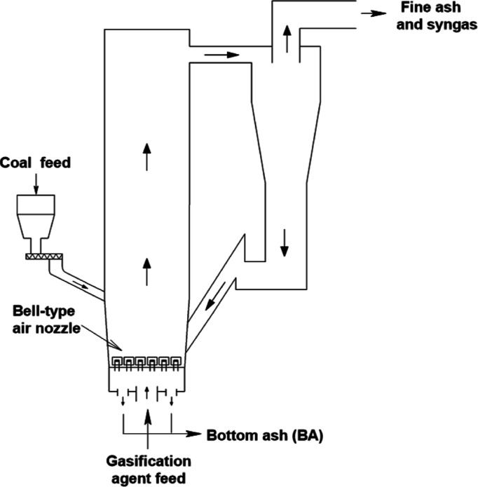
As shown in Figure 1, coal particles are added to the gasifier from the bunker, and the gasification agent enters the bottom of the gasifier via an air nozzle and contacts with the coal particles. As the gasification agent has a certain pressure and flow rate, the coal particles are in a fluidized state. Usually, coal particles undergo four stages in the gasifier: drying, pyrolysis, combustion, and gasification. A portion of the residual ash is denser and discharged from the slag outlet at the bottom of the gasifier, known as BA. The other solid particles with less dense are carried out by the produced syngas. Passing through the cyclone separator, most of the particles return to the bottom of the gasifier and participate in the gasification process again, while the finer particles are carried by the gas and enter the subsequent separation process.3
Figure 1.
Circulating fluidized-bed gasifier.
The structure of the bell-type air nozzle at the bottom of circulating fluidized-bed gasifier is shown in Figure 2. Upper portion of the air nozzle consists of two parts, the nozzle cover and the core tube, and the core tube is directly connected to the guide duct. There are four round holes at the top of the core tube, and two rows of round holes (eight holes per row) are around the upper part. The lower side wall of the nozzle cover has a row of oval-shaped holes as the final outlet of the gasification agent. The gasification agent enters the air nozzle from the guide duct, sprays out through the round holes of the core tube, and finally enters the bottom of the gasifier through the oval-shaped holes.7
Figure 2.
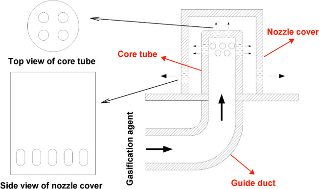
Bell-type air nozzle structure diagram.
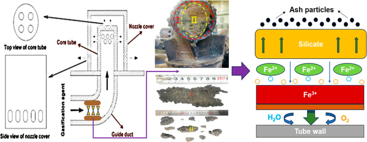
The blocked part of the guide duct is shown in Figure 3a, and its cross section is shown in Figure 3b. As can be seen from Figure 3b, the blockage is roughly divided into two parts, one for the wall-layer blockage (WLB) and the other for the center-layer blockage (CLB), corresponding to I and II areas in Figure 3b respectively. Among them, WLB shows a rough, dark gray surface, high density, and strength, which may be related to the high-temperature corrosion of the metal tube. However, CLB presents a gray irregular lumpy shape with low density and strength, as shown in Figure 3c. The cause may be that when the high-temperature gasification agent carried ash backward by some reasons, the ash met the lower temperature of inner wall surface of the duct, particles containing Fe2+ in the ash will quickly deposit on the surface of the duct, forming an initial blockage layer.8 The surface temperature of the slag increased as the growth of the slag, once the temperature of surface slag exceeded the deposited slag melting point, the surface would keep molten state, and then captured more ash particles, eventually blocking the duct completely.9 In addition, the blockage in the I area has a strong adhesion at the duct wall and is difficult to be separated from the wall. It is possible that the deposited ash eroded in the wall with the presence of steam in the gasification agent, resulting in a tight fit.
Figure 3.
Location and morphology of the two blockages: (a) used bell-type air nozzle, (b) blockage in the air nozzle, and (c) morphology of the two regions (I and II) of the blockage.
2.2. Sample Pretreatment and Analysis
As shown in Figure 3, the samples (WLB and CLB) are taken from Xinjiang Yihua Chemical Industry Co. Ltd. and dried in an oven at 105 °C for 4 h before the tests.
The crystalline composition of the samples was analyzed using an X-ray diffractometer (RIKEN-Ultima IV, Japan) with a scanning angle of 10–90° and scanning time of 50 min. The ash composition was analyzed by an X-ray fluorescence spectrometer (Panacol ZETIUM+ microarea spectroscopy). The surface microstructure was characterized with a scanning electron microscope (German-Zeiss sigma 500). The type of the functional group was analyzed by a Fourier transform infrared spectrometer (Japan—Shimadzu—IR Tracer 100), and the wavelength range was set as 400–4000 cm–1. The pore structure of the samples was tested by the N2 adsorption–desorption method at 77 K, and the instrument used was American—Mac-3FLEX.
3. Results and Discussion
3.1. Element Content of the Blockage
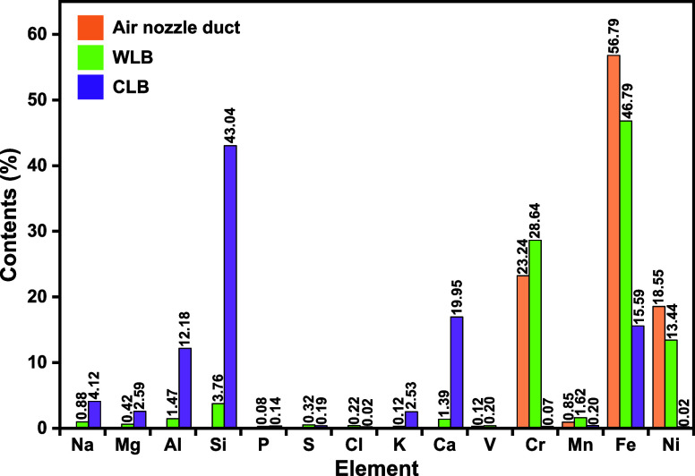
Elemental composition of the air nozzle guide duct and the two blockages is shown in Figure 4. The main elements in guide duct are Fe, Cr, and Ni, with the contents of 56.79, 23.24, and 18.55%, respectively. Oxidation resistance of the above metals is in the order of Ni > Cr > Fe.10 Large amounts of Cr (28.64%) found in WLB indicate that serious Cr migration or corrosion occurred during the gasification process.
Figure 4.
Elemental composition of air nozzle guide duct and the two blockages.
Elemental contents in WLB and CLB differs considerably. The main elements in WLB are Cr, Fe, and Ni, similar to the guide duct. In addition to Cr, Fe, and Ni, WLB also contains small amounts of Si, Al, Ca, and Na. As can be seen from Figure 4, the Fe content in WLB is as high as 46.79%, indicating that Fe in the WLB mainly came from the corrosion of the inner wall of the guide duct. WLB contains a certain amount of V and Cl, mainly coming from the coal particles, both of which would accelerate the corrosion rate of the duct.11−13
The elements in CLB are mainly Si, Ca, Fe, Al, Na, Mg, and K. Al2O3 and SiO2 are presented in large quantities in the residual ash,3 which are highly refractory, indicating that CLB is mainly derived from ash deposition from the raw coal rather than oxidative corrosion of the duct. The content of Fe in CLB, with the percentage of 15.59%, is significantly lower than that of WLB and higher than that of residual ash (9.77%).3 It is presumed that Fe in CLB was derived from the migration of Fe in the WLB, followed by that of the BA. In addition, the enrichment of alkali metals in CLB might be a premise for the migration of Fe because particles rich in Fe can be easily deposited after alkali metals condensed.14
3.2. Crystalline Phase Composition of the Blockage
Results of the crystalline composition of the two blockages are shown in Figure 5. Crystal in WLB are mainly Cr, Fe3O4, and FeNi, with diffraction peaks of FeCr2O4 presented. Fe3O4 was probably formed by the oxidative corrosion of Fe in the duct, while FeCr2O4 would be generated by the following reaction: FeO + Cr2O3 = FeCr2O4.15 There is no Cr element in the BA from ref (3), it is inferred that Cr in the WLB came from the guide duct, indicating that high-temperature corrosion of the duct occurred during the gasification process.
Figure 5.
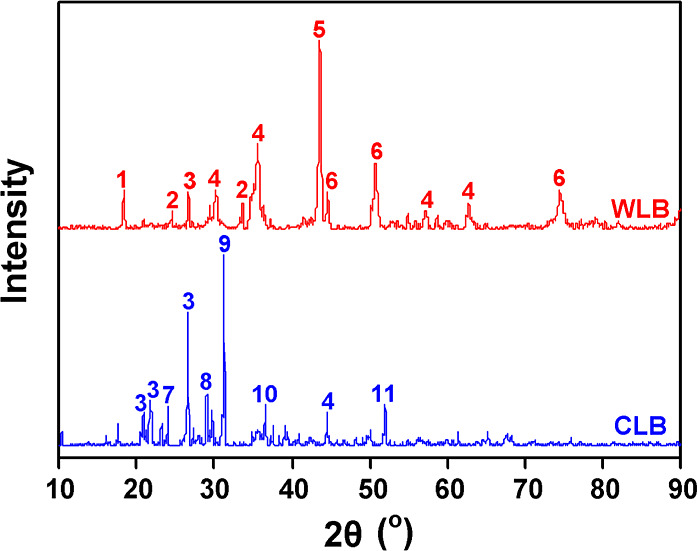
XRD patterns of WLB and CLB (1-FeCr2O4, 2-Cr2O3, 3-SiO2, 4-Fe3O4, 5-Cr, 6-FeNi, 7-NaAlSiO4, 8-Fe2Al4Si5O18, 9-Ca2MgSi2O7, 10-Mg2SiO4, and 11-Ca4Al2MgSi3O14).
Crystals in CLB are mainly silica and silicates, and the silicates contain AAEMs, which have low melting points and are often in a molten state at the gasification temperature. From Figure 5, sodium mainly presents in the form of NaAlSiO4, the same as the sodium form of BA presented in another ZSBC-based coal gasifier.2 Thus, CLB was mainly derived from the BA, probably caused by slag leakage from the air nozzle pores. In addition, small amounts of Fe3O4 and Fe2Al4Si5O18 are detected in CLB. It is speculated that Fe in the guide duct might be involved in the high-temperature reaction, and that low melting point silicates were formed to exacerbate the deposition of blockage. Song et al.16 found that Fe was found to act as a medium in the deposition process.
3.3. Functional Group Distribution of the Blockage
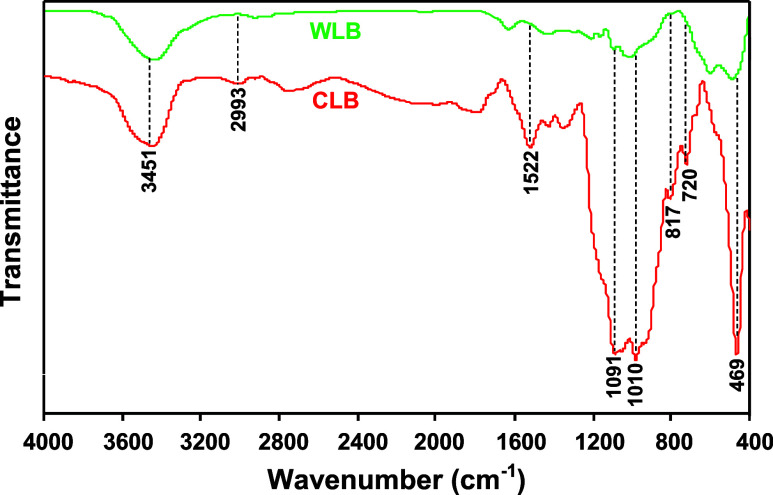
Figure 6 shows the infrared spectra of WLB and CLB. The main functional group regions can be divided into four parts, the hydroxyl part at 3600–3100 cm–1, the aliphatic region at 3000–2800 cm–1, the area of other oxygen-containing functional groups at 1800–1000 cm–1, and the range of aromatic ring at 900–700 cm–1.17,18
Figure 6.
Infrared spectra of the WLB and CLB.
As can be seen from Figure 6, CLB has more types of absorption peaks than WLB, and the peaks are more intense, which was attributed to the different generation modes of the two blockages (WLB is mainly due to high-temperature corrosion of metals from the guide duct and CLB due to ash accumulation). The absorption peaks at 1522 cm–1 (C=C in ARs), 817 cm–1 (four adjacent H deformations), and 720 cm–1 (two adjacent H deformations) are only found in CLB, indicating the presence of more aromatic structures. The peak of 3451 cm–1 is attributed to the stretching vibration of the hydroxyl hydrogen bond, suggesting the presence of –OH in both blockages. The weak absorption peaks at 2993 cm–1 for both blockages are mainly attributed to the bending vibrations of aliphatic –CH2 and –CH3, indicating the presence of aliphatic side chains or methylene bridge bonds between aromatic rings in the two blockages.
Strong absorption peaks are observed at both 1091 and 1010 cm–1. These peaks are caused by typical infrared absorption of silica–aluminates and quartz in the sample.19 High intensity and sharp shape of the peaks from CLB indicate that the sample contains a large amount of coal ash, particularly silica-bearing minerals, which is consistent with the previous elemental and crystalline analyses. The peak produced by Si–O bending vibration can be seen near 469 cm–1, and the intensity of which from CLB is also much higher than that of WLB, which is also related to the large amount of silicate minerals contained in CLB.
3.4. Morphology and Element Distribution of the Blockage
3.4.1. Morphology and Element Distribution of WLB
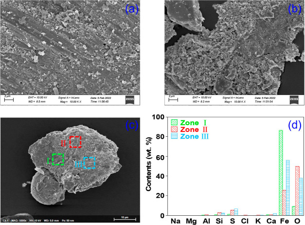
Figure 7 shows the morphology and elemental distribution of WLB. WLB has a plate-like structure with rough surface and some small particles attached. In addition, scratches can be found on the surface, which might be caused by particle washout as the ash leaking into the guide duct and being reblown up. The indeterminate particles attached to the surface of WLB may be the ash adsorbed by low melting point eutectics. From Figure 7b, some of the WLB surface has more particles and a loose structure. It can be assumed that during the initial stage of slagging in the guide duct, there are number of irregular particles adhered to the surface and underwent melt sintering, exacerbating the deposition and blockage.
Figure 7.
Morphology and element distribution of WLB: scanning electron microscopic (SEM) image of (a) base and (b) attached slag from WLB, (c) three element testing points, and (d) elemental distribution of the three points in WLB.
From Figure 7c, regions I, II, and III were taken for EDS element distribution test, which can be seen in Figure 7d. Area I is mainly dominated by Fe, followed by O. High content of Fe indicates that the selected sample mainly originates from the guide duct itself (this sample is closely adhered to the wall of guide duct and difficult to be dislodged from the duct wall). It is presumed to be the initial stage of duct blockage.
Area II presents a high O content, followed by Fe, and a certain amount of S and Si. Obviously, Fe is mainly present in the form of oxides in Area II. Volatile Fe-based oxides are enriched on the surface of ash particles by homogeneous nucleation or heterogeneous condensation during high temperature.20 Fe2+ and ash particles generate eutectics on the metal surface and adhere to the ash,21 and Fe2+ in the eutectics is easily oxidized.
High Fe and O contents in region III can be observed, followed by S and Ca. The literature shows that Ca is not presented as calcium silicate salts, but may be CaSO4, produced by the sulfation of CaO.22 From our previous work,3 S and Ca were found in the BA, indicating that the particles containing S and Ca are mainly from BA.
3.4.2. Morphology and Element Distribution of CLB
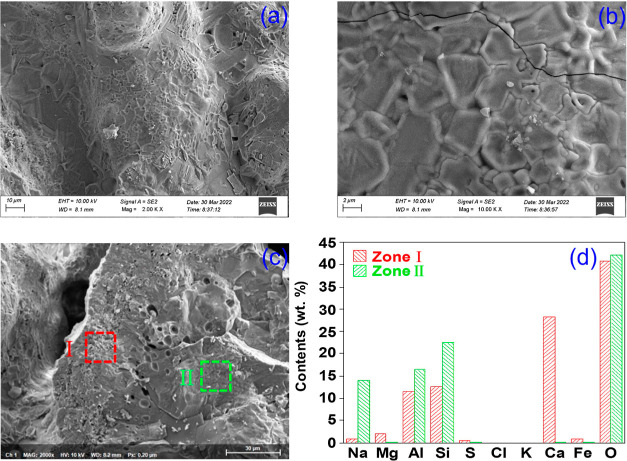
Figure 8 shows the morphology and element distribution of CLB. It can be found that edges of CLB particles have fused to form a smooth surface with distinct raised lines, suggesting the formation of eutectics, possibly due to the low melting point particles. In addition, CLB contains high amounts of silica and silicates, suggesting that agglomerates and fused particles are formed mainly from eutectic compounds, silicates and (complex) sulfates, which can decrease the melting point of the sediment.16
Figure 8.
Micromorphology and element distribution of CLB: (a,b) SEM images of CLB with different magnification, (c) three element testing points, and (d) elemental distribution of the three points in CLB.
Figure 8 shows the morphology of CLB particles from two regions. Region I is the outer part of the particles with the elements of O, Ca, Si, Al, Mg, Na, and Fe. From the XRD profile, Ca2MgSi2O7, Fe2Al4Si5O18, and SiO2 can be found in the mineral phases. They are the same as the inorganic compounds in the BA slag, indicating that CLB is mainly derived from the conversion of particles in the ash slag at the bottom of the gasifier. Particularly, Ca/O atom ratio in this region is 0.67, suggesting that CaO might be present in CLB in addition to Ca2MgSi2O7. The deposition of these calcium-containing substances, especially Ca2MgSi2O7, on the surface of particles would make the heated surface more susceptible to melting.23
Region II is the inner layer of particles, which is more compact compared to the outer layer. Except for the O element, which is not much different from region I, Si, Al, and Na elements account for a higher proportion. Si is mainly SiO2, followed by alkali-metal compounds, such as NaAlSiO4. For Al, according to some literature, Al-based compounds could act as the skeleton of ash slag.24 From Figure 8c, it can also be found that there are a small number of bubble-like holes between the two regions, which might be due to the formation of small amounts of volatile FeCl2 and FeCl3 (melting point of each compound is 676 and 303 °C, respectively) during the formation of CLB under high temperature.25 Thus, the production of FeCl2 and FeCl3 could accelerate the migration of Fe.
3.4.3. Surface Element Distribution of CLB (Mapping Analysis)
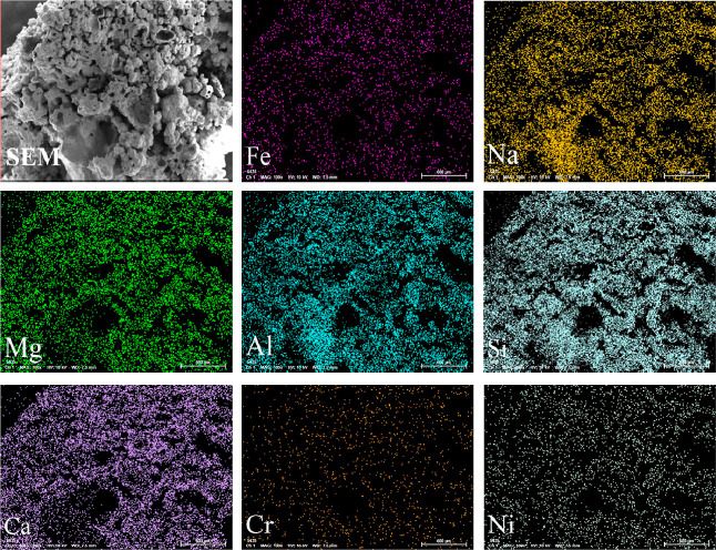
Figure 9 shows the element mapping of CLB at a low magnification (100×). It can be observed obviously that the surface of CLB is not smooth but coral-like, with obvious sintering marks, large and irregular particles. The elements of Na, Mg, Al, Si, and Ca are widely distributed and present strong signals, indicating that the CLB surface is mainly composed of silicate particles containing alkali and alkaline earth metals. Although Fe, Cr, and Ni elements are also distributed, the mapped signals are relatively weak, demonstrating that Fe, Cr, and Ni in the air nozzle guide duct wall can migrate to WLB easily, and to CLB more or less. During the formation of the blockage, the above elements may interact with silicate melts to form solid solutions or new silicate-like compounds.
Figure 9.
Morphology and element mapping of CLB.
3.5. Formation Mechanism of the Blockage
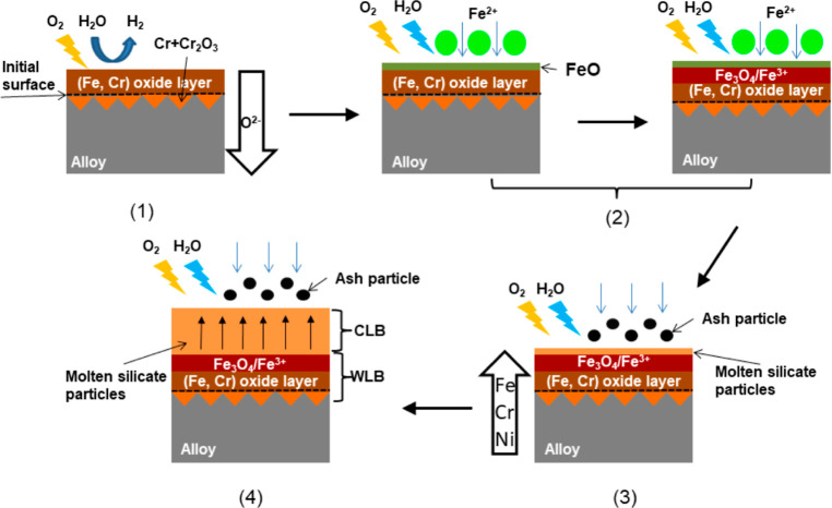
Based on the above analysis results, the formation mechanism of the blockage in the air nozzle guide duct is proposed and is shown in Figure 10.
Figure 10.
Possible formation mechanism of the blockage.
In the environment of 900–1100 °C gasification agents (air, oxygen, steam, etc.), it is easy to lead to the generation of the oxide layer in the contact wall. That is, under certain conditions, the BA in the gasifier may be carried by the agent gas to the air nozzle holes and to the guide duct. In the process, small ash particles were attached to the duct wall. By reacting with the oxide layer, deposition and agglomeration of the ash particles may take place, and the thickness of the deposition layer will be increased. Ultimately, the ash particles could completely block the guide duct. From Figure 10, the formation mechanism of the blockage can be illustrated as five stages:
-
(1)
In oxidizing atmosphere, at high temperature, a protective Fe–Cr oxide layer is initially generated on the duct wall (alloy). O2 and H2O dissociate at the gas–solid interface to generate O2–, which will diffuse to the inward layer of the wall, where Cr and its oxide coexist. The literature showed that steam tended to accelerate the depletion of Cr at metal matrix interface as well as in the oxide layer.26 However, O2 is the main factor in the initial formation of oxide layer on the surface of the alloy.27
-
(2)
Fe2+ or FeO containing particles in ash would be the first compound to deposit on the duct wall in a molten state. Under oxidizing conditions, Fe2+ was gradually oxidized and converted to Fe3+ or magnetite, which was a different mechanism to the deposition of sedimentary ash particles.14
-
(3)
As the silicate particles containing AAEMs are adsorbed, a molten silicate fouling layer begins to form on the surface, and the FeO melt underneath is further oxidized, while Fe, Cr, and Ni in the wall will migrate to the fouling layer. In this case, Fe reacts with the silicate fouling layer to form some Fe-based compounds, such as Fe2Al4Si5O18 (shown in Figure 5).
-
(4)
Large amounts of ash particles are adsorbed by the viscous molten silicate to form low melting point eutectics on the surface, gradually increasing the thickness of the deposition layer over time, and eventually blocked the guide duct.
To inhibit or slow the generation of guide duct blockage, the following suggestions based on relevant analyses are given out:
-
(1)
Optimizing air nozzle with more wear-resistant and heat-resistant materials, or using spraying technology to slow down corrosion.
-
(2)
Increasing the distance between air nozzles to avoid mutual interference from ash particles at the bottom of the gasifier, and appropriately reducing gasification agent speed to reduce the wear of guide conduct inner wall.
-
(3)
Adjusting the particle size of incoming raw coal, so that the particles in the gasifier can be in a stable fluidization state for a long time.
4. Conclusions
Characteristics and formation mechanism of the blockage from the air nozzle guide duct in an industrial circulating fluidized-bed gasifier with ZSBC as raw material are revealed in this work. The main conclusions are as follows:
-
(1)
The guide duct blockage is caused by ash corrosion at high temperature. The blockage can be divided into two parts—CLB and WLB. CLB is mainly composed of silica–aluminates acting as a skeleton, and silicate eutectics can also be found. While WLB mostly consisted metal oxides by Fe, Cr, and Ni.
-
(2)
In gasification condition (900–1100 °C), the guide duct wall will be oxidized and corroded to produce oxide layer, especially Fe and Cr. Ash is the primary deposit in guide duct elbow and may react with the oxide layer on the duct wall.
-
(3)
Optimizing air nozzle with more wear-resistant and heat-resistant materials and adjusting the distance between air nozzles to avoid mutual interference from ash particles are presented to avoid or inhibit the formation of the blockage.
Acknowledgments
The project was supported by the National Natural Science Foundation of China (22368045), the High Quality Development Special Project for Science and Technology Supporting Industry from Changji prefecture, Xinjiang, China (2022Z04) “Research, Development and Application of Key Technologies for Improving Quality and Efficiency in Coal Chemical Industry”, and the State Key Laboratory of Chemistry and Utilization of Carbon-Based Energy Resources “Element migration and transformation mechanism and reactor simulation and optimization of fluidized-bed gasifier based on Zhundong coal”.
The authors declare no competing financial interest.
References
- Liu Z.; Li J.; Zhu M.; Cheng F.; Lu X.; Zhang Z.; Zhang D. An experimental investigation into the effect of flue gas recirculation on ash deposition and Na migration behaviour in circulating fluidized bed during combustion of high sodium Zhundong lignite. Fuel Process. Technol. 2020, 199, 106300. 10.1016/j.fuproc.2019.106300. [DOI] [Google Scholar]
- Song G.; Qi X.; Song W.; Yang S.; Lu Q.; Nowak W. Slagging behaviors of high alkali Zhundong coal during circulating fluidized bed gasification. Fuel 2016, 186, 140–149. 10.1016/j.fuel.2016.08.075. [DOI] [Google Scholar]
- Hu X.-B.; Yang X.-Q.; Mo W.-L.; Zhang S.-P.; Ji G.; Wei X.-Y.; Fan X. Structural characteristics and thermal conversion performance of ash and slag from circulating fluidized bed gasifier. J. Fuel Chem. Technol. 2022, 50 (10), 1361–1371. 10.1016/s1872-5813(22)60024-0. [DOI] [Google Scholar]
- Mirek P.; Klajny M. Air nozzle design criteria for protection against the backflow of solids in CFB boilers. Appl. Therm. Eng. 2018, 141, 503–515. 10.1016/j.applthermaleng.2018.06.006. [DOI] [Google Scholar]
- Omer A.; Weng M. Effect of primary air maldistribution due to nozzle wear on CFBC performance. Fuel Process. Technol. 2018, 173, 191–196. 10.1016/j.fuproc.2017.12.008. [DOI] [Google Scholar]
- Huang Z. Reason analysis on abrasion and ash leakage of bell-type air nozzle in a circulating fluidized bed boiler. Therm. Power Gener. 2014, 43 (4), 102–109. 10.3969/j.issn.1002-3364.2014.04.102. [DOI] [Google Scholar]
- Huang Z.; Zhang S.-G. Optimization of large-diameter bell-type air cap in CFB boiler. Electr. Power Constr. 2014, 35 (5), 4. 10.3969/i.issn.1000-7229.2014.05.014. [DOI] [Google Scholar]
- Wang J.; Wei B.; Li X.; Yang W.; Zhang C.; Mian I.; Tan H.; Ma F. Study on reduction characteristics of Fe species in coal ash under SNCR condition. Fuel 2020, 277, 118231. 10.1016/j.fuel.2020.118231. [DOI] [Google Scholar]
- Liu K.; Lu Q.; Wei B.; Wang J.; Chen L.; Wu W.; Tan H.; Li X. Effect of particle system on slag formation and shedding characteristics of high alkali metal coal in full-scale circulating fluidized bed boiler based on Nano-CT. Fuel Process. Technol. 2021, 223, 106995. 10.1016/j.fuproc.2021.106995. [DOI] [Google Scholar]
- Song G.; Qi X.; Yang S.; Yang Z. Investigation of ash deposition and corrosion during circulating fluidized bed combustion of high-sodium, high-chlorine Xinjiang lignite. Fuel 2018, 214, 207–214. 10.1016/j.fuel.2017.11.011. [DOI] [Google Scholar]
- Sidhu T.-S.; Prakash S.; Agrawa R.-D. Hot corrosion and performance of nickel-based coatings. Curr. Sci. India 2006, 90 (1), 41–47. [Google Scholar]
- Sidhu T. S.; Prakash S.; Agrawal R. D. Performance of high-velocity oxyfuel-sprayed coatings on an Fe-based superalloy in Na2SO4-60%V2O5 environment at 900 °C Part I: Characterization of the coatings. J. Mater. Eng. Perform. 2006, 15 (1), 122–129. 10.1361/105994906x83402. [DOI] [Google Scholar]
- Arivazhagan N.; Singh S.; Prakash S.; Reddy G. M. Hot corrosion studies on dissimilar friction welded low alloy steel and austenitic stainless steel under chlorine containing salt deposits under cyclic conditions. Corros Eng. Sci. Technol. 2009, 44 (5), 369–380. 10.1179/147842208X338974. [DOI] [Google Scholar]
- Liu Y.; Cheng L.; Ji J.; Zhang W. Ash deposition behavior in co-combusting high-alkali coal and bituminous coal in a circulating fluidized bed. Appl. Therm. Eng. 2019, 149, 520–527. 10.1016/j.applthermaleng.2018.12.080. [DOI] [Google Scholar]
- Xiong X.; Lv Z.; Tan H.; Wei B. A typical super-heater tube leakage and high temperature corrosion mechanism investigation in a 260 t/h circulated fluidized boiler. Eng. Failure Anal 2020, 109 (1), 104255. 10.1016/j.engfailanal.2019.104255. [DOI] [Google Scholar]
- Qi X.; Song G.; Song W.; Yang S.; Lu Q. Effects of wall temperature on slagging and ash deposition of Zhundong coal during circulating fluidized bed gasification. Appl. Therm. Eng. 2016, 106 (4), 1127–1135. 10.1016/j.applthermaleng.2016.06.092. [DOI] [Google Scholar]
- Qin Z.-H.; Chen H.; Yan Y.-J.; Li C.-S.; Rong L.-M.; Yang X.-Q. FTIR quantitative analysis upon solubility of carbon disulfide/N-methyl-2-pyrrolidinone mixed solvent to coal petrographic constituents. Fuel Process. Technol. 2015, 133, 14–19. 10.1016/j.fuproc.2015.01.001. [DOI] [Google Scholar]
- Zhao Y.; Qiu P.; Chen G.; Pei J.; Sun S.; Liu L.; Liu H. Selective enrichment of chemical structure during first grinding of Zhundong coal and its effect on pyrolysis reactivity. Fuel 2017, 189, 46–56. 10.1016/j.fuel.2016.10.083. [DOI] [Google Scholar]
- Xie X.; Zhao Y.; Qiu P.; Lin D.; Qian J.; Hou H.; Pei J. Investigation of the relationship between infrared structure and pyrolysis reactivity of coals with different ranks. Fuel 2018, 216, 521–530. 10.1016/j.fuel.2017.12.049. [DOI] [Google Scholar]
- Namkung H.; Xu L.-H.; Shin W. C.; Kang T.-J.; Kim H.-T. Study on deposition tendency of coal ash under various gasification environments through DTF. Fuel 2014, 117, 1274–1280. 10.1016/j.fuel.2013.07.028. [DOI] [Google Scholar]
- Li G.; Wang C.; Wang P.; Du Y.; Liu X.; Chen W.; Che D. Ash deposition and alkali metal migration during Zhundong high-alkali coal gasification. Energy Procedia 2017, 105, 1350–1355. 10.1016/j.egypro.2017.03.497. [DOI] [Google Scholar]
- Dai B.-Q.; Low F.; De Girolamo A.; Wu X.; Zhang L. Characteristics of ash deposits in a pulverized lignite coal-fired boiler and the mass flow of major ash-forming inorganic elements. Energy Fuels 2013, 27 (10), 6198–6211. 10.1021/ef400930e. [DOI] [Google Scholar]
- Wang X.; Xu Z.; Wei B.; Zhang L.; Tan H.; Yang T.; Mikulčić H.; Duić N. The ash deposition mechanism in boilers burning Zhundong coal with high contents of sodium and calcium: A study from ash evaporating to condensing. Appl. Therm. Eng. 2015, 80, 150–159. 10.1016/j.applthermaleng.2015.01.051. [DOI] [Google Scholar]
- Nielsen H. P.; Frandsen F. J.; Dam-Johansen K.; Baxter L. L. The implications of chlorine-associated corrosion on the operation of biomass-fired boilers. Prog. Energy Combust. Sci. 2000, 26 (3), 283–298. 10.1016/s0360-1285(00)00003-4. [DOI] [Google Scholar]
- Jiang D.; Song W.; Wang X.; Zhu Z. Physicochemical properties of bottom ash obtained from an industrial CFB gasifier. J. Energy Inst. 2021, 95, 1–7. 10.1016/j.joei.2020.12.004. [DOI] [Google Scholar]
- Alviz-Meza A.; Duong A.; Orozco-Agamez J.; Kafarov V.; Cárdenas-Escorcia Y.; Carrillo-Caballero G.; Peña-Ballesteros D. Study of early P91 dual corrosion in steam and simulated combustion gases from a gas-fired boiler. J. Mater. Res. Technol. 2021, 13, 271–282. 10.1016/j.jmrt.2021.04.071. [DOI] [Google Scholar]
- Li K.; Zeng Y.; Luo J.-L. Corrosion performance of candidate boiler tube alloys under advanced pressurized oxy-fuel combustion conditions. Energy 2021, 215, 119178. 10.1016/j.energy.2020.119178. [DOI] [Google Scholar]


