Abstract
Flexible and transparent microelectrodes and interconnects provide the unique capability for a wide range of emerging biological applications, including simultaneous optical and electrical interrogation of biological systems. For practical biointerfacing, it is important to further improve the optical, electrical, electrochemical, and mechanical properties of the transparent conductive materials. Here, high-performance microelectrodes and interconnects with high optical transmittance (59–81%), superior electrochemical impedance (5.4–18.4 Ω cm2), and excellent sheet resistance (5.6–14.1 Ω sq−1), using indium tin oxide (ITO) and metal grid (MG) hybrid structures are demonstrated. Notably, the hybrid structures retain the superior mechanical properties of flexible MG other than brittle ITO with no changes in sheet resistance even after 5000 bending cycles against a small radius at 5 mm. The capabilities of the ITO/MG microelectrodes and interconnects are highlighted by high-fidelity electrical recordings of transgenic mouse hearts during co-localized programmed optogenetic stimulation. In vivo histological analysis reveals that the ITO/MG structures are fully biocompatible. Those results demonstrate the great potential of ITO/MG interfaces for broad fundamental and translational physiological studies.
Keywords: transparent microelectrodes, flexible, metal grids, indium tin oxide, electrophysiology
ToC figure
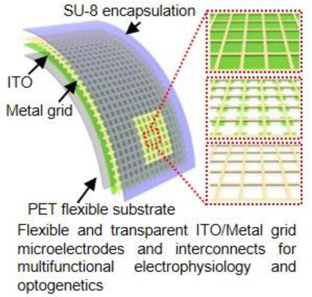
Flexible and transparent microelectrodes and interconnects are designed for simultaneous co-localized electrical and optical interrogation of biological systems. The innovative indium tin oxide/metal grid hybrid composites show superior electrical conductivity, electrochemical performance, optical transmittance, and mechanical flexibility. Proof-of-concept demonstrations reveal that the transparent microelectrodes can record electrical signals from transgenic mouse hearts under co-localized optical pacing.
1. Introduction
Electrophysiology applies electronics technology to monitor bioelectrical activities of neurons,[1] cardiomyocytes,[2] and signal propagations in brain[3] and heart[4] tissues in vitro,[5] in vivo,[6,7] and in clinical medicine.[8,9] However, tissue and organ level electrophysiology technology has limited cell-type specificity and thus provides no direct information on which cell populations under investigation contribute to the measured bioelectrical signals. Optogenetics, an emerging optical technique that allows stimulating/inhibiting the functions of specific cell-types using light-sensitive ion channels, has become increasingly essential in many areas of biological research. Crosstalk-free integration of electrophysiological recording with optogenetic modulation is highly desired to combine the full advantages of both techniques and enable bidirectional interfacing with biological systems.[10] Ideally, the electrical signals should be recorded at the same anatomic sites where the optical interventions are introduced. However, conventional opaque metal-based electrodes and interconnects are not suitable for such purposes because they create optical obstacles between the cell/tissue and light source.[11,12]
The development of transparent microelectrodes based on indium tin oxide (ITO),[13] graphene,[14,15] and carbon nanotube (CNT)[16] enables efficient light delivery through the microelectrodes for electrophysiological recording with co-localized optogenetic modulation or calcium imaging using external light sources or microscopes.[15–19] ITO has a low sheet resistance (Rs) and high optical transmittance (T). It is the most widely used transparent electrode material in optoelectronic devices such as organic light-emitting diodes (LEDs), organic solar cells, and touch panels.[20–22] However, the intrinsic rigidity and brittleness of ITO constrains its application to curvilinear bio-surfaces. For graphene and CNT, their properties are sensitive to fabrication technologies[23] and their Rs is typically much higher than that of ITO.[14] In addition, graphene and CNT microelectrodes suffer from controversial reports of the cytotoxicity and carcinogenicity for chronic applications.[24–26] Flexible transparent conductive metal grid (MG) structures provide a pragmatic solution. The Rs and T of MGs can be adjusted by changing grid width, pitch, and thickness.[27] Unlike graphene and CNT, the low Rs and electrochemical impedance of MGs allows them to serve as transparent interconnects and microelectrodes to enable optical interrogation of the entire device area.[28] However, in MG structures, the large open spaces among the interconnected metal lines will significantly reduce both the effective abiotic/biotic interfacial surface recording area and density of charge transport network. Therefore, the high T of MGs comes at a cost of undesired increase in sheet resistance and electrochemical impedance for biological applications. Existing strategies to reduce the interface impedance of MG microelectrodes originate from those used for opaque metal-based microelectrodes[29,30] and mostly rely on coating low impedance materials such as conductive polymers[31] and iridium oxide[32] on the metal lines. Until now, methods to design transparent MG microelectrodes and interconnects with low electrode impedance and sheet resistance by engineering the open spaces between interconnected metal lines remain largely unexplored.
Here, we report for the first time ITO/MG hybrid microelectrodes and interconnects with superior conductivity, electrochemical impedance, mechanical flexibility, and optical transparency for biological applications. Covering the open spaces between MGs with highly electrically conductive and optically transparent ITO significantly increases the effective charge transport pathways and interfacial recording areas without changing the geometrical surface area. The optimized hybrid microelectrodes exhibit a high average T at 81 ± 1.9% from 400 nm to 800 nm with significantly reduced Rs (14.1 Ω sq−1) and normalized impedance (18.4 Ω cm2) compared to those of the pristine MG microelectrodes (Rs of 26.8 Ω sq−1 and normalized impedance of 212.1 Ω cm2). Importantly, the hybrid microelectrodes possess similar levels of mechanical flexibility to the pristine MG microelectrodes, overcoming the brittleness of ITO. Detailed studies show that the hybrid design is applicable to different grid structures and metal materials. Functionalities of the hybrid microelectrodes and interconnects are demonstrated by proof-of-concept ex vivo electrophysiological recording of electrogram (EG) signals from transgenic mouse hearts during sinus rhythm and cardiac dysfunction under simultaneous optogenetic pacing using external LEDs. In vivo histology studies reveal that the hybrid structures are biocompatible. Together, those results demonstrate innovative transparent conductive material composites and effective design strategies to achieve transparent microelectrodes with superior electrochemical impedance, low sheet resistance, high optical transparency, and excellent mechanical flexibility for important biological applications combining electrophysiology and optogenetics.
2. Results and Discussion
2.1. Design of ITO/MG Hybrid Microelectrodes and Interconnects
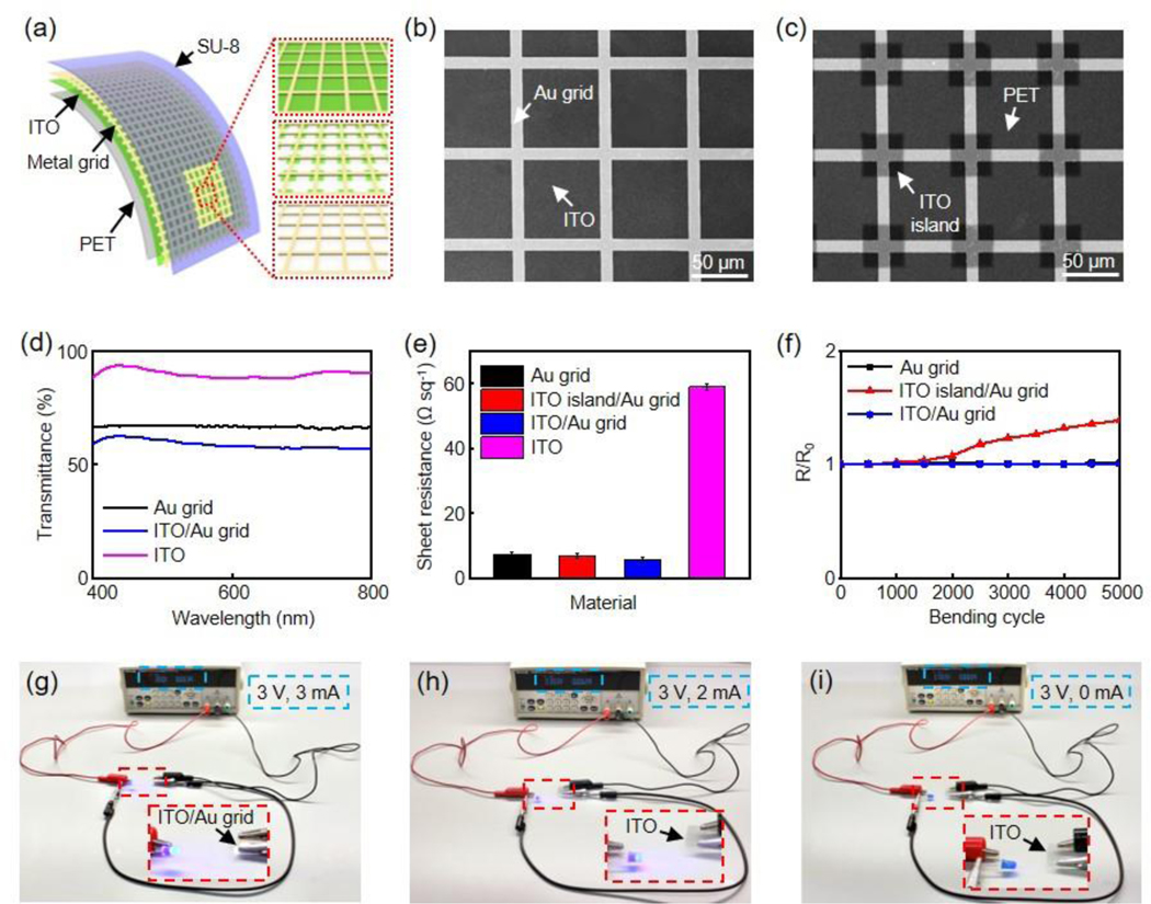
Figure 1a demonstrates a schematic illustration of the flexible transparent microelectrodes and interconnects in this work, including MG, ITO island/MG, ITO/MG structures on polyethylene terephthalate (PET) films (thickness 127 μm), respectively. Figure 1b and 1c present the scanning electron microscope (SEM) images of ITO/Au grid and ITO island/Au grid, respectively. In both structures, Au grid exhibits a width at 10 μm and a pitch at 80 μm. This grid width is chosen because sub-10 μm lines are imperceptible to human eye.[27,33] In addition, similar ratios between grid pitch and width are adopted in various metal grid structures for optoelectronics applications.[34–36] The dimension of the ITO island is 38 × 38 μm2. The thicknesses of Au grid and ITO are 80 nm and 40 nm, respectively.
Figure 1.
(a) Schematic illustration of flexible and transparent ITO/metal grid hybrid microelectrodes and interconnects (left), ITO/metal grid (right top), ITO island/metal grid (right middle) and metal grid (right bottom). SEM images of (b) ITO/Au grid and (c) ITO island/Au grid, respectively. Scale bar, 50 μm. (d) Transmission spectra of Au grid, ITO/Au grid, and ITO, respectively. (e) Sheet resistance of Au grid, ITO island/Au grid, ITO/Au grid, and ITO, respectively. (f) Variation of sheet resistance versus bending cycle for Au grid, ITO island/Au grid, and ITO/Au grid, respectively. The bending radius is 5 mm. Photos of an operating blue LED connected by (g) ITO/Au grid hybrid electrode after 10000 bends, (h) pristine ITO electrode, and (i) ITO electrode after 2 bends. The bending radius is 5 mm.
2.2. Optical, Electrical, and Mechanical Properties of the Microelectrodes and Interconnects
Figure 1d shows the transmission spectra of ITO, Au grid and ITO/Au grid. The 40 nm ITO exhibits an average transmittance over 90% in the visible range. As a result, stacking ITO with Au grid results in only a minor decrease in transmittance compared to pristine Au grid. For example, transmittance value at 550 nm drops from 67% in Au grid to 59% in ITO/Au grid hybrid structure.
Figure 1e illustrates the Rs of the four transparent conductive structures. As expected, covering the open spaces between interconnected Au grids partially or fully with ITO leads to decreased Rs from 7.4 ± 0.6 Ω sq−1 (Au grid) to 6.9 ± 0.6 Ω sq−1 (ITO island/Au grid), and further to 5.6 ± 0.7 Ω sq−1 (ITO/Au grid), respectively. In contrast, the Rs of the ITO film used in this work is 59 ± 0.9 Ω sq−1 and literature Rs values of the CNT and graphene microelectrodes are generally over 100 Ω sq-1.[37–39] Due to their superior conductivity, the ITO/Au grid hybrid structures can act as the transparent interconnects for the microelectrodes as discussed later.
Although ITO cracks easily, the Au grid in the hybrid structures will electrically connect cracked ITO layer, leading to superior mechanical flexibility of the ITO/Au grid film. Figure 1f demonstrates changes in Rs from Au grid, ITO island/Au grid, and ITO/Au grid films during repeated mechanical bending under a bending radius of 5 mm. The bending radius is similar to the anatomical structures of interest in small animal models.[40,41] The Rs values of Au grid and ITO/Au grid films remain unchanged even after 5000 cycles while the Rs of ITO film increases by 23.2% after the first cycle. It is important to note that the mechanical properties of the hybrid ITO/Au grid composites are among the best for ITO-based transparent conductive materials. [41–43] Figure 1g shows an optical image of a blue LED connected to 3 V voltage supply by the ITO/Au grid interconnects after 10000 bending cycles at 5 mm radius, confirming its excellent mechanical flexibility. It is worth noting that even after 10000 bending cycles, the resistance of the ITO/Au grid interconnects is still significantly smaller than that from the pristine unbent ITO films, determined by the current and voltage values shown on the voltage supply (Figure 1h). Meanwhile, pristine ITO interconnects break and fail to turn on the blue LED after only 2 bending cycles (Figure 1i).
2.3. Electrochemical Properties of the Microelectrodes
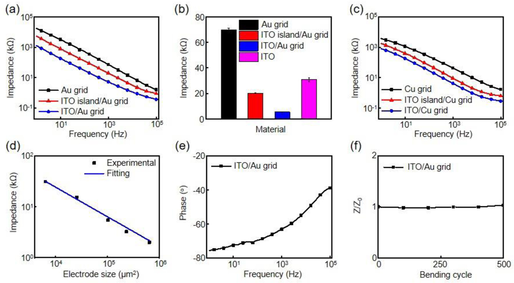
Electrochemical impedance spectroscopy (EIS) is a useful tool to investigate the biophysical properties of the microelectrodes. Figure 2 summarizes the electrochemical performance of the microelectrodes measured in a phosphate-buffered saline (PBS) solution. The size of the microelectrodes is 320 × 320 μm2, if not specifically mentioned. Figure 2a presents the impedance spectra of Au grid, ITO island/Au grid and ITO/Au grid microelectrodes with frequencies ranging from 1 Hz to 100 kHz. As expected, Au grid exhibits the highest impedance, while ITO/Au grid has the lowest impedance over the whole frequency range. The microelectrode impedance value at 1 kHz generally serves as a benchmark for determining the electrochemical performance.[14] As shown in Figure 2b, the impedance values at 1 kHz decrease from 70.7 ± 1.4 kΩ (Au grid) to 20.3 ± 0.2 kΩ (ITO island/Au grid), and further to 5.3 ± 0.2 kΩ (ITO/Au grid), respectively. The 13-fold decrease in impedance in the ITO/Au grid microelectrodes results from the dramatically increased effective interfacial recording area. Moreover, the impedance of the ITO/Au grid hybrid microelectrodes is much lower than that of the pristine ITO (30.8 ± 1.5 kΩ). Importantly, this design strategy can be applied to other metals such as copper. Figure 2c shows the impedance spectra of Cu grid, ITO island/Cu grid, ITO/Cu grid microelectrodes with the same grid parameters. Similarly, the impedance values at 1 kHz decrease from 43.5 ± 2.2 kΩ in Cu grid to 4.3 ± 0.2 kΩ in ITO/Cu grid microelectrodes.
Figure 2.
(a) Impedance plots of Au grid, ITO island/Au grid, and ITO/Au grid microelectrodes. The microelectrode size is 320 × 320 μm2. (b) Average impedance values (5 samples each) of Au grid, ITO island/Au grid, ITO/Au grid, and ITO microelectrodes at 1 kHz, respectively. (c) Impedance plots of Cu grid, ITO island/Cu grid, and ITO/Cu grid microelectrodes. (d) Impedance versus electrode size for ITO/Au grid hybrid microelectrodes. (e) Phase plot of the ITO/Au grid hybrid microelectrodes in (a). (f) Variation of impedance versus bending cycle for ITO/Au grid hybrid microelectrodes. The bending radius is 5 mm. Z0 is the impedance before bending whereas Z represents the impedance at a specific bending cycle.
Figure 2d illustrates the 1 kHz impedance of ITO/Au grid microelectrodes at different electrode areas. The impedance shows a near-precise dependence on A−1, where A is the electrode area, indicating a capacitive interface.[18,28] Phase spectra in Figure 2e further demonstrate that the microelectrodes show mostly capacitive behavior with phase angles between −60o to −75o at physiologically relevant frequencies (1 Hz to 1 kHz) and become more resistive at higher frequencies. In addition, the impedance of the encapsulated microelectrode film is stable after 500 bending cycles against a radius of 5 mm (Figure 2f), which is desired for electrophysiology measurements.
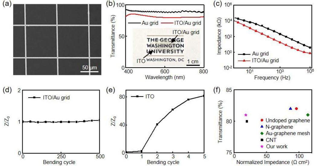
To meet higher optical requirements, the transmittance of the MGs can be improved by increasing the ratio between grid pitch and width.[27] Meanwhile, this will result in an undesired decrease in electrochemical performance due to the reduced effective interfacial recording area. Our ITO/MG design provides a versatile strategy to address this challenge. Figure 3a exhibits the SEM image of a new ITO/Au grid hybrid structure with a grid pitch at 90 μm and width at 3 μm. This large ratio (30) between pitch and width leads to a high average transmittance at 81 ± 1.9% from 400 nm to 800 nm for the hybrid structures (Figure 3b). The transmittance values at 468 nm and 550 nm are 84% and 81%, respectively. The normalized impedance at 1 kHz of the new ITO/Au grid microelectrodes is 18.4 Ω cm2, significantly lower than that of the Au grid microelectrodes (212.1 Ω cm2) with the same grid parameters (3 μm width and 90 μm pitch), as shown in Figure 3c. Despite the reduced grid density, the new ITO/Au grid hybrid microelectrodes still exhibit a superior mechanical flexibility with stable impedance after 500 repeated bending cycles against a radius at 5 mm (Figure 3d). In contrast, the impedance value of the ITO microelectrodes exhibits a 40-fold increase after only 2 bending cycles (Figure 3e). The sheet resistance of the new ITO/Au grid film is 14.1 Ω sq−1 while that of new Au grid film alone is 26.8 Ω sq−1.
Figure 3.
(a) SEM image of the new ITO/Au grid. Scale bar, 50 μm. (b) Transmission spectra of an Au grid and an ITO/Au grid. (Inset) optical image of the ITO/Au grid film on a logo of The George Washington University. Scale bar, 1 cm. (c) Impedance plots of Au grid and ITO/Au grid microelectrodes, respectively. Variation of impedance versus bending cycle for (d) ITO/Au grid and (e) ITO microelectrode films. The bending radius is 5 mm. Z0 is the impedance before bending whereas Z represents the impedance at a specific bending cycle. (f) Comparison of transmittance versus normalized impedance of our ITO/Au grid hybrid microelectrodes compared with other reported representative transparent microelectrodes with transmittance ≥ 80% for electrophysiology.
To highlight the superior performance of the ITO/Au grid hybrid microelectrodes, they are compared to other representative state-of-the-art flexible transparent microelectrodes previously reported for electrophysiology studies with transmittance values exceeding 80%, including undoped graphene,[40] nitrogen-doped graphene,[15] Au-doped graphene mesh[44] and CNT[16]. It is noteworthy that among those highly transparent microelectrodes, the ITO/Au grid exhibits one of the best electrochemical performance, which is advantageous to achieve low noises during electrophysiological recording.
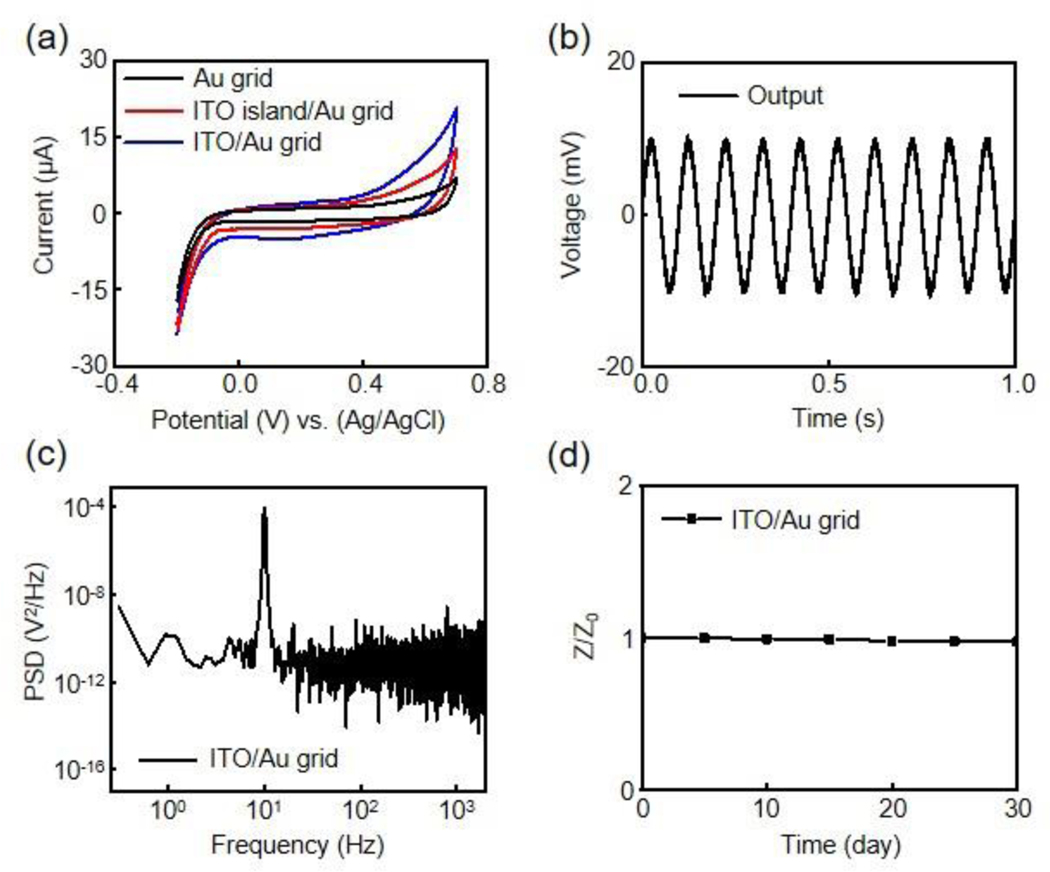
To better understand the electrochemical behaviors of ITO/Au grid hybrid microelectrodes, cyclic voltammetry (CV) measurements are conducted and compared with Au grid and ITO island/Au grid microelectrodes. Figure 4a shows CV results of the three microelectrodes measured at 100 mV s−1 from −0.2 V to 0.7 V to prevent water electrolysis. All three microelectrodes exhibit no redox peaks, suggesting double-layer capacitive electrode/solution interfaces.[45] Moreover, the ITO/Au grid hybrid microelectrodes show the largest integrated area under the CV curve, indicating the highest capacitance due to their maximized effective interfacial area. Figure 4b presents the electrical benchtop recording results of a 10 Hz sine wave input signal with 20 mV peak-to-peak amplitude using the ITO/Au grid microelectrodes in a PBS solution. A platinum wire delivers the input signal to the PBS solution. The microelectrodes show a high-fidelity recording with no decrease in signal amplitude. The power spectrum density (PSD) of the recorded signals provides more details into the noise signals in the frequency domain. The large peak of the PSD spectrum in Figure 4c is from the 10 Hz input signal. After filtering, the ITO/Au grid hybrid microelectrodes show a root-mean-square noise of 26 μV, and a signal-to-noise ratio (SNR) of 48.4 dB. The SNR is higher than other previously reported transparent recording microelectrodes.[19,28] In addition, metal grid transparent electrodes are known to exhibit much smaller light-induced electrical artifacts compared to solid metal electrodes caused by Becquerel effect due to less metal in the electrode window.[32,36]Figure 4d presents the soaking test results for up to 30 days in a PBS solution at room temperature, during which the impedance of the ITO/Au grid hybrid microelectrodes remains unchanged, indicating their excellent durability for chronic applications.
Figure 4.
(a) CV curves of Au grid, ITO island/Au grid, and ITO/Au grid microelectrodes at 100 mV/s. (b) Electrical benchtop recording output of a 10 Hz, 20 mV peak-to-peak input sine wave in a PBS solution from an ITO/Au grid hybrid microelectrode. (c) Power spectral density of the recorded sine wave from the ITO/Au grid hybrid microelectrode in (b). (d) Variation of impedance versus soaking time for an encapsulated ITO/Au grid hybrid microelectrode. Z0 is the impedance before soaking test whereas Z represents the impedance on a specific day.
2.4. Electrophysiological Measurements
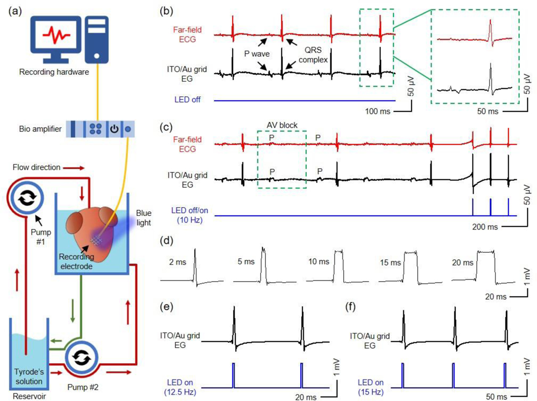
Ex vivo cardiac measurements demonstrate the practical feasibility of the ITO/Au grid hybrid microelectrodes and interconnects in biological studies, where the microelectrodes not only record the EG signals from transgenic adult mouse hearts during sinus rhythm and cardiac dysfunction (atrioventricular (AV) block) but also allow for recording with simultaneous optogenetic pacing of channelrhodopsin-2 (ChR2) expressing cardiomyocytes directly underneath the microelectrodes to capture paced heart rhythms. Figure 5a shows the experimental setup, where the microelectrodes laminate to the right ventricle of a Langendorff-perfused mouse heart. The thin geometry and superior flexibility of the microelectrodes allow for a conformal contact on the heart. A blue LED serves as the light source for optogenetic pacing. Standard far-field electrocardiogram (ECG) electrode serves as the reference. Figure 5b presents physiological signals recorded during sinus rhythm. The EG signals from the ITO/Au grid hybrid microelectrodes and reference electrode exhibit similar morphologies. The average durations of QRS complexes (n = 5) from the ITO/Au grid hybrid microelectrodes and the reference electrode are 8.3 ± 0.4 ms, and 8.2 ± 0.3 ms, respectively. The results show that the ITO/Au grid microelectrodes enable high-fidelity electrophysiological recording.
Figure 5.
(a) Schematic illustration of the Langendorff-perfusion setup used for electrophysiological recording and optogenetic pacing of ChR2-expressing mouse hearts in this work. The heart is perfused with Tyrode’s solution in a custom-designed chamber at 37 °C. Pump #1 perfuses the heart, and Pump #2 circulates solution throughout the chamber. An ITO/Au grid hybrid microelectrode is laminated onto the right ventricle of the heart and connected to a bio amplifier that interfaces with a computer where signals are recorded. (b) (Left) Far-field ECG and electrogram recordings of normal sinus rhythm from a reference electrode and an ITO/Au grid hybrid microelectrode with the blue LED turned off, respectively. (Right) Representative P waves and QRS complexes recorded by the reference electrode and ITO/Au grid hybrid microelectrode. (c) Electrogram recording from the ITO/Au grid hybrid microelectrode during 2nd degree AV block with and without simultaneous optogenetic pacing with a blue LED pulsing at 10 Hz (lower blue curve). The electrogram signals during optogenetic pacing are divided by 20 to present similar scale to that of the signals acquired during intrinsic rhythms. (d) Representative QRS complexes recorded by the ITO/Au grid hybrid microelectrode in response to blue LED stimulation at 2, 5, 10, 15, 20 ms, respectively. Representative electrogram recordings of heart rhythm from the ITO/Au grid hybrid microelectrode with the blue LED pulsing at (e) 12.5 Hz and (f) 15 Hz, respectively.
2nd degree AV block, a common bradyarrhythmia, was introduced by low-flow ischemia to investigate the utility of the ITO/Au grid hybrid microelectrodes in simultaneous electrophysiology and optogenetic studies of pathological cardiovascular physiology. The dissociation between the P wave and QRS complex in Figure 5c shows that the ITO/Au grid hybrid microelectrodes can successfully capture AV block. Meanwhile, the microelectrodes allow the passage of blue light from LEDs (10 Hz and 1% duty cycle) to enable optogenetic ventricular pacing and capture of the underlying cardiomyocytes. The recorded AV block and pacing signals from the ITO/Au grid hybrid microelectrodes exhibit morphologies that are almost identical to those observed in the reference far-field electrodes. The recorded signals from the ITO/Au grid hybrid microelectrodes in Figure 5d further reveal that the durations of the QRS complexes can be precisely controlled by programming the blue light pulse widths (2 ms, 5 ms, 10 ms, 15 ms, 20 ms). This is strikingly different from electrical stimulation, which opens sodium channels with fast inactivation kinetics (~1 ms), unlike ChR2 with opening time dependent on the duration of light pulse. The optimal pacing frequency is selected to be higher than the heart’s intrinsic rhythm, which differs from subject to subject. Figure 5e and 5f present the EG recording results from the ITO/Au grid hybrid microelectrodes with the LED operating at 12.5 Hz and 15 Hz (blue curves), respectively. Meanwhile, the ITO/Au grid hybrid structures serve as transparent interconnects for the microelectrodes, which avoid the requirement of additional opaque metal-based interconnects and enable optogenetic stimulation to the entire device area. Together, those results indicate that the ITO/Au grid hybrid microelectrodes and interconnects are good candidates for simultaneous electrophysiology and optogenetics research.
2.5. Histology Studies
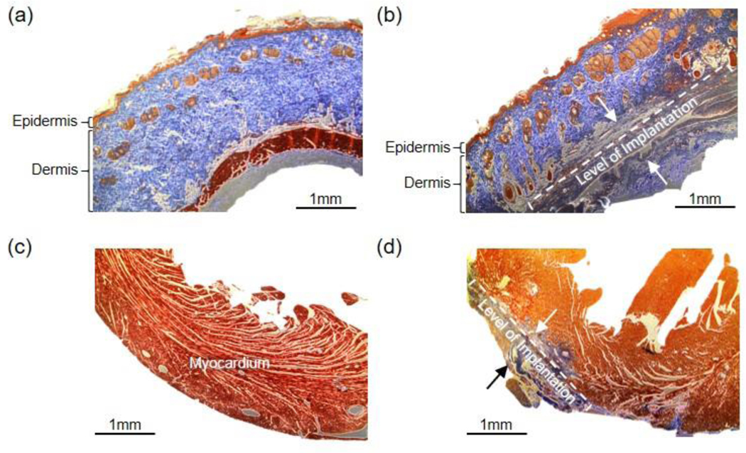
The microelectrodes and interconnects were implanted into both the dorsal skin and the anterior epicardial surface of the ventricles of rats to evaluate their biocompatibility. The rats were sacrificed four weeks after implantation, and the collected tissues were stained with Masson’s trichrome. For subcutaneous implantation, the mechanical damage from surgical implantation led to some disorganized collagen tissues in the subcutaneous layer, while the epidermal and dermal tissues show no adverse reaction compared to healthy skin (Figure 6a and 6b). For epicardial implantation, some cardiac hypertrophy and increased fibrotic tissue at the epicardium are observed at the implant region compared to healthy myocardium (Figure 6c and 6d). These changes are expected for prolonged exposure of mechanically contracting tissues to any foreign object. Overall, the histology results indicate the ITO/Au grid hybrid composites exhibit excellent biocompatibility.
Figure 6.
Histological assessment of device biocompatibility (a-d). (a) Healthy soft tissue. (b) Soft tissue reaction to subcutaneous device implantation. The dotted bracket indicates the stretch of subcutaneous tissue with evidence of remodeling and scar tissue formation. Tissue remodeling is prominent between the two black arrows. The epidermal and dermal tissue do not have signs of remodeling. (c) Healthy myocardium. (d) Myocardium after anterior device implantation. The fibrotic tissue (blue) is seen at the site of device implantation on the surface of the myocardium. The extent of scar tissue fibrosis thickness can be seen between the two black arrows. Scale bar, 1 mm.
3. Conclusion
In this work, we successfully demonstrate both ex vivo and in vivo high-performance flexible and transparent ITO/Au grid hybrid microelectrodes and interconnects. Covering the open spaces between the interconnected MGs with ITO can significantly improve the electrical and electrochemical performance of the microelectrodes without sacrificing the mechanical flexibility and optical transparency. By carefully controlling the parameters of the ITO/Au grid hybrid structures, high optical transmittance (average transmittance at 81 ± 1.9% from 400 nm to 800 nm), good conductivity (sheet resistance at 14.1 Ω sq−1), superior electrochemical performance (normalized 1 kHz impedance of 18.4 Ω cm2), and excellent mechanical flexibility (stable impedance performance after 500 bending cycles under a 5 mm bending radius) are achieved. The fabrication of the ITO/MG hybrid microelectrodes and interconnects utilizes straightforward simple photolithography steps and can be applied to various metals. Those features are favorable for broad optoelectronic applications, such as solar cells, displays, LEDs, implantable and wearable sensors, etc. Proof-of-concept ex vivo demonstrations suggest the feasibility of the microelectrodes for simultaneous electrophysiology and optogenetics applications. In vivo histology studies of the device’s integration into the skin and the heart reveal the full biocompatibility of the ITO/Au grid hybrid composites. Overall, the flexible and transparent ITO/MG hybrid microelectrodes and interconnects can facilitate novel experimental designs combining electrophysiology with optophysiology, and they serve as promising candidates for the next generation multifunctional optoelectronic biointerfaces.
4. Experimental Section
Microelectrode and Interconnect Fabrication:
ITO coated PET film (Sigma-Aldrich) was first laminated on a glass slide using polydimethylsiloxane (PDMS) adhesive. To fabricate ITO island patterns, a photolithographically patterned photoresist layer (AZ P4620, Integrated Micro Materials) served as the mask, followed by wet etching in a 5% hydrochloric acid. Photolithographic patterning, sputter deposition, and lift-off in acetone prepared the Cr/Au (5 nm/ 80 nm) and Cr/Cu (5 nm/ 80 nm) layers with different geometries on PET, PET/ITO island, and PET/ITO film. A 7 μm thick photodefinable SU-8 epoxy (SU-8 2007, Microchem) encapsulated the microelectrodes and interconnects.
Optical Measurement:
Transmission spectra were measured with a spectrophotometer (V-770 UV-visible/NIR, Jasco Inc.). Emission profiles of the LEDs were measured by a spectrometer (AvaSpec-ULS2048L, Avantes).
SEM Characterization:
The morphologies of the samples were examined with SEM (PIONEER EBL, Raith Inc.) at an accelerating voltage of 10.0 kV.
Electrical Measurement:
Sheet resistance was measured by a four-point probe (SRM-232, Guardian Manufacturing Inc.).
Electrochemical Measurement:
The electrochemical properties of the microelectrodes were investigated by EIS and CV, in a three-electrode cell using a Gamry potentiostat (Reference 600+, Gamry Instruments Inc.). EIS measurements were conducted with the frequency ranging from 1 Hz to 100 kHz. The CV tests were measured at a potential window from −0.2 V to 0.7 V. Scan rates were 100 mV/s. For the three-electrode system, the Au grid, ITO island/Au grid, ITO/Au grid, Cu grid, ITO island/Cu grid, and ITO/Cu grid microelectrodes served as the working electrode, a platinum wire and a Ag/AgCl electrode served as the counter and reference electrodes, respectively. The system was tested in a PBS solution (Sigma-Aldrich).
Electrical Benchtop Test:
A 10 Hz 20 mV peak-to-peak sine wave signal was input into a PBS solution from a platinum electrode by a PowerLab data acquisition system (PowerLab 16/35, ADInstruments Inc.). The ITO/Au grid hybrid microelectrode and a reference platinum electrode were connected to different channels in PowerLab for comparison. The PSD was exported to MATLAB for signal processing.
Mouse model:
For the optical stimulation experiments, commercially available transgenic mice (The Jackson Laboratory) were bred to express ChR2 specifically in the myocytes as previously described.[46]
Ex Vivo Demonstration:
Ex vivo demonstrations of the devices were performed with adult mice expressing ChR2 in the heart. Mice were quickly anesthetized using isoflurane, and cessation of pain was verified by pinching of the toe. An open thoracotomy was performed to expose and excise the heart. Following cannulation, the heart was Langendorff-perfused with oxygenated (95% O2 / 5% CO2) modified Tyrode’s solution (in mм: 128.2 NaCl, 4.7 KCl, 1.05 MgCl2, 1.3 CaCl2, 1.19 NaH2PO4, 20 NaHCO3, and 11.1 glucose) at 37 °C, and aortic pressure was maintained between 60 and 80 mmHg. Microelectrode EG and reference ECG signals were recorded by three electrodes placed in the perfusion bath. A strength-duration curve was generated by determining the LED light intensity threshold to achieve capture of the heart rhythm for each duty cycle (1, 2, 5, 10, 20%) at a pacing frequency of 10 Hz (600 BPM), which was faster than the heart’s intrinsic heart rate. The hybrid microelectrodes were placed on the posterior side of the heart for all recorded signals. For optogenetic pacing, a LED was placed on the posterior side of the heart outside of the microelectrodes. Photons from the LED pass through the microelectrodes and reach the cardiomyocytes directly under the microelectrodes. Electrical signals were acquired by a PowerLab data acquisition system at a sampling frequency of 1 kHz and analyzed using LabChart software (ADInstruments Inc.). AV block was induced by ischemic reperfusion of the heart. All experiments were completed within 3 hours of isolating the heart. The electrical signals recorded from the microelectrodes and standard steel needle electrodes with needle length of 12 mm (Model No. MLA1203, ADInstruments Inc.) were filtered by a 0.5 Hz to 2 kHz bandpass filter.
In Vivo Implantation and Histological Analysis Procedure:
All animal procedures were performed according to protocols approved by the Institutional Animal Care and Use Committee of The George Washington University. Recommendations of the Panel of Euthanasia of the American Veterinary Medical Association and the National Institutes of Health Guide for the Care and Use of Laboratory Animals were also implemented. Cardiac implantation procedures were performed as previously described.[46] Subdermal implantation of the microelectrodes was performed immediately following the cardiac implantation procedure. The rat was placed in a prone position, and a 2 cm2 area on the back was shaved and sterilized with chlorhexidine gluconate/isopropyl alcohol solution. A 1 cm transverse incision was made on the dorsum, and a small subcutaneous pocket was created by blunt dissection. The microelectrodes were inserted into the subcutaneous pocket and the skin incision was closed with a running monofilament suture. Following surgery, the animals recovered well and exhibited normal level of activity. Hearts and subcutaneous samples were harvested 4 weeks after implantation, fixed with 10% neutral-buffered formalin, paraffin embedded, sectioned, and stained with Masson’s trichrome. Samples were examined and images recorded using an EVOS XL light microscope (Thermo Fisher Scientific).
Acknowledgements
Z. C and R. T. Y contributed equally to this work. We thank The George Washington University Nanofabrication and Imaging Center for its facilities regarding device fabrication. We thank Dr. Tatiana Efimova for her guidance in the histological analysis of the skin. L. L. was supported by The George Washington University, Department of Biomedical Engineering start-up funds. I. R. E. acknowledges Leducq Foundation grant RHYTHM and National Institutes of Health grants (3OT2OD023848 and R01HL141470). R. T. Y. was supported by the American Heart Association Predoctoral Fellowship (19PRE34380781).
References
- [1].Heuschkel MO, Fejtl M, Raggenbass M, Bertrand D, Renaud P, Neurosci J. Methods 2002, 114, 135. [DOI] [PubMed] [Google Scholar]
- [2].Jones JL, Lepeschkin E, Jones RE, Rush S, Am. J. Physiol. Circ. Physiol 1978, 235, H214. [DOI] [PubMed] [Google Scholar]
- [3].Williamson A, Rivnay J, Kergoat L, Jonsson A, Inal S, Uguz I, Ferro M, Ivanov A, Sjöström TA, Simon DT, Berggren M, Malliaras GG, Bernard C, Adv. Mater 2015, 27, 3138. [DOI] [PubMed] [Google Scholar]
- [4].Duan X, Gao R, Xie P, Cohen-Karni T, Qing Q, Choe HS, Tian B, Jiang X, Lieber CM, Nat. Nanotechnol 2012, 7, 174. [DOI] [PMC free article] [PubMed] [Google Scholar]
- [5].Berdondini L, Van Der Wal PD, Guenat O, de Rooij NF, Koudelka-Hep M, Seitz P, Kaufmann R, Metzler P, Blanc N, Rohr S, Biosens. Bioelectron 2005, 21, 167. [DOI] [PubMed] [Google Scholar]
- [6].Buzsáki G, Nat. Neurosci 2004, 7, 446. [DOI] [PubMed] [Google Scholar]
- [7].Cheung KC, Renaud P, Tanila H, Djupsund K, Biosens. Bioelectron 2007, 22, 1783. [DOI] [PubMed] [Google Scholar]
- [8].Zrenner E, Sci. Transl. Med 2013, 5, 210ps16. [DOI] [PubMed] [Google Scholar]
- [9].Normann RA, Fernandez E, J. Neural Eng 2016, 13, 61003. [DOI] [PubMed] [Google Scholar]
- [10].Pei F, Tian B, Adv. Funct. Mater 2019, 1906210. [Google Scholar]
- [11].Wu F, Stark E, Ku P-C, Wise KD, Buzsáki G, Yoon E, Neuron 2015, 88, 1136. [DOI] [PMC free article] [PubMed] [Google Scholar]
- [12].Zhao Z, Luan L, Wei X, Zhu H, Li X, Lin S, Siegel JJ, Chitwood RA, Xie C, Nano Lett. 2017, 17, 4588. [DOI] [PMC free article] [PubMed] [Google Scholar]
- [13].Kunori N, Takashima I, J. Neurosci. Methods 2015, 251, 130. [DOI] [PubMed] [Google Scholar]
- [14].Park D-W, Schendel AA, Mikael S, Brodnick SK, Richner TJ, Ness JP, Hayat MR, Atry F, Frye ST, Pashaie R, Thongpang S, Ma Z, Williams JC, Nat. Commun 2014, 5, 5258. [DOI] [PMC free article] [PubMed] [Google Scholar]
- [15].Liu X, Lu Y, Iseri E, Shi Y, Kuzum D, Front. Neurosci 2018, 12, 132. [DOI] [PMC free article] [PubMed] [Google Scholar]
- [16].Zhang J, Liu X, Xu W, Luo W, Li M, Chu F, Xu L, Cao A, Guan J, Tang S, Duan X, Nano Lett. 2018, 18, 2903. [DOI] [PubMed] [Google Scholar]
- [17].Lee W, Someya T, Chem. Mater 2019, 31, 6347. [Google Scholar]
- [18].Park D-W, Ness JP, Brodnick SK, Esquibel C, Novello J, Atry F, Baek D-H, Kim H, Bong J, Swanson KI, Suminski AJ, Otto KJ, Ramin P, Williams JC, Ma Z, ACS Nano 2018, 12, 148. [DOI] [PubMed] [Google Scholar]
- [19].Kuzum D, Takano H, Shim E, Reed JC, Juul H, Richardson AG, De Vries J, Bink H, Dichter MA, Lucas TH, Coulter DA, Cubukcu E, Litt B, Nat. Commun 2014, 5, 5259. [DOI] [PMC free article] [PubMed] [Google Scholar]
- [20].Chen Z, Obaid SN, Lu L, Opt. Mater. Express 2019, 9, 3843. [Google Scholar]
- [21].Cao W, Li J, Chen H, Xue J, Photonics Energy J 2014, 4, 40990. [Google Scholar]
- [22].Kim S-R, Yoo J-H, Park J-W, ACS Appl. Mater. Interfaces 2019, 11, 15088. [DOI] [PubMed] [Google Scholar]
- [23].Bae S, Kim H, Lee Y, Xu X, Park J-S, Zheng Y, Balakrishnan J, Lei T, Kim HR, Il Song Y, Kim Y-J, Kim KS, Özyilmaz B, Ahn J-H, Hong BH, Iijima S, Nat. Nanotechnol 2010, 5, 574. [DOI] [PubMed] [Google Scholar]
- [24].Zhang Y, Ali SF, Dervishi E, Xu Y, Li Z, Casciano D, Biris AS, ACS Nano 2010, 4, 3181. [DOI] [PubMed] [Google Scholar]
- [25].Sakamoto Y, Hojo M, Kosugi Y, Watanabe K, Hirose A, Inomata A, Suzuki T, Nakae D, J. Toxicol. Sci 2018, 43, 587. [DOI] [PubMed] [Google Scholar]
- [26].Hansen SF, Lennquist A, Nat. Nanotechnol 2020, 15, 3. [DOI] [PubMed] [Google Scholar]
- [27].Lee HB, Jin W-Y, Ovhal MM, Kumar N, Kang JW, J. Mater. Chem. C 2019, 7, 1087. [Google Scholar]
- [28].Seo KJ, Qiang Y, Bilgin I, Kar S, Vinegoni C, Weissleder R, Fang H, ACS Nano 2017, 11, 4365. [DOI] [PubMed] [Google Scholar]
- [29].Khodagholy D, Gelinas JN, Thesen T, Doyle W, Devinsky O, Malliaras GG, Buzsáki G, Nat. Neurosci 2015, 18, 310. [DOI] [PMC free article] [PubMed] [Google Scholar]
- [30].Eick S, Wallys J, Hofmann B, van Ooyen A, Schnakenberg U, Ingebrandt S, Offenhäusser A, Front. Neuroeng 2009, 2, 16. [DOI] [PMC free article] [PubMed] [Google Scholar]
- [31].Qiang Y, Artoni P, Seo KJ, Culaclii S, Hogan V, Zhao X, Zhong Y, Han X, Wang P-M, Lo Y-K, Li Y, Patel HA, Huang Y, Sambangi A, Chu JSV, Liu W, Fagiolini M, Fang H, Sci. Adv 2018, 4, eaat0626. [DOI] [PMC free article] [PubMed] [Google Scholar]
- [32].Qiang Y, Seo KJ, Zhao X, Artoni P, Golshan NH, Culaclii S, Wang P, Liu W, Ziemer KS, Fagiolini M, Fang H, Adv. Funct. Mater 2017, 27, 1704117. [Google Scholar]
- [33].Jang Y, Kim J and Byun D, J. Phys. D: Appl. Phys 2013, 46, 155103. [Google Scholar]
- [34].Kang MG, Guo LJ, Adv. Mater 2007, 19, 1391. [Google Scholar]
- [35].Li LJ, Zhang B, Zou B, Xie R, Zhang T, Li S, Zheng B, Wu J, Weng J, Zhang W, Huang W, Huo F, ACS Appl. Mater. Interfaces 2017, 9, 39110. [DOI] [PubMed] [Google Scholar]
- [36].Obaid SN, Yin RT, Tian J, Chen Z, Chen SW, Lee KB, Boyajian N, Miniovich AN, Efimov IR, Lu L, Adv. Funct. Mater 2020, 1910027. [DOI] [PMC free article] [PubMed] [Google Scholar]
- [37].Dan B, Irvin GC, Pasquali M, ACS Nano 2009, 3, 835. [DOI] [PubMed] [Google Scholar]
- [38].Yamada T, Ishihara M, Hasegawa M, Thin Solid Films 2013, 532, 89. [Google Scholar]
- [39].Yang J, Liu P, Wei X, Luo W, Yang J, Jiang H, Wei D, Shi R, Shi H, ACS Appl. Mater. Interfaces 2017, 9, 36017. [DOI] [PubMed] [Google Scholar]
- [40].Thunemann M, Lu Y, Liu X, Kılıç K, Desjardins M, Vandenberghe M, Sadegh S, Saisan PA, Cheng Q, Weldy KL, Lyu H, Djurovic S, Andreassen OA, Dale AM, Devor A, Kuzum D, Nat. Commun 2018, 9, 2035. [DOI] [PMC free article] [PubMed] [Google Scholar]
- [41].Jimbo Y, Matsuhisa N, Lee W, Zalar P, Jinno H, Yokota T, Sekino M, Someya T, ACS Appl. Mater. Interfaces 2017, 9, 34744. [DOI] [PubMed] [Google Scholar]
- [42].Datta RS, Syed N, Zavabeti A, Jannat A, Mohiuddin M, Rokunuzzaman M, Yue Zhang B, Rahman MA, Atkin P, Messalea KA, Ghasemian MB, Gaspera ED, Bhattacharyya S, Fuhrer MS, Russo SP, McConville CF, Esrafilzadeh D, Kalantar-Zadeh K, Daeneke T, Nat. Electron 2020, 3, 51. [Google Scholar]
- [43].Sakamoto K, Kuwae H, Kobayashi N, Nobori A, Shoji S, Mizuno J, Sci. Rep 2018, 8, 2825. [DOI] [PMC free article] [PubMed] [Google Scholar]
- [44].Kim SJ, Cho KW, Cho HR, Wang L, Park SY, Lee SE, Hyeon T, Lu N, Choi SH, Kim D, Adv. Funct. Mater 2016, 26, 3207. [Google Scholar]
- [45].Rufford TE, Hulicova-Jurcakova D, Khosla K, Zhu Z, Lu GQ, J. Power Sources 2010, 195, 912. [Google Scholar]
- [46].Gutruf P, Yin RT, Lee KB, Ausra J, Brennan JA, Qiao Y, Xie Z, Peralta R, Talarico O, Murillo A, Chen SW, Leshock JP, Haney CR, Waters EA, Zhang C, Luan H, Huang Y, Trachiotis G, Efimov IR, Rogers JA, Nat. Commun 2019, 10, 5742. [DOI] [PMC free article] [PubMed] [Google Scholar]


