Abstract
Patients with long conductive implants such as deep brain stimulation (DBS) leads are often denied access to magnetic resonance imaging (MRI) exams due to safety concerns associated with radiofrequency (RF) heating of implants. Experimental temperature measurements in tissue-mimicking gel phantoms under MRI RF exposure conditions are common practices to predict in-vivo heating in the tissue surrounding wire implants. Such experiments are both expensive—as they require access to MRI units—and time-consuming due to complex implant setups. Recently, full-wave numerical simulations, which include realistic MRI RF coil models and human phantoms, are suggested as an alternative to experiments. There is however, little literature available on the accuracy of such numerical models against direct thermal measurements. This study aimed to evaluate the agreement between simulations and measurements of temperature rise at the tips of wire implants exposed to RF exposure at 64 MHz (1.5 T) for different implant trajectories typically encountered in patients with DBS leads. Heating was assessed in seven patient-derived lead configurations using both simulations and RF heating measurements during imaging of an anthropomorphic head phantom with implanted wires. We found substantial variation in RF heating as a function of lead trajectory; there was a 9.5-fold and 9-fold increase in temperature rise from ID1 to ID7 during simulations and experimental measurements, respectively. There was a strong correlation (r2 = 0.74) between simulated and measured temperatures for different lead trajectories. The maximum difference between simulated and measured temperature was 0.26 °C with simulations overestimating the temperature rise.
I. INTRODUCTION
Magnetic resonance imaging (MRI) is a leading neuroimaging procedure due to its high resolution, noninvasive method, and unparalleled soft tissue contrast. These characteristics of MRI indicate that it is well-suited for postoperative monitoring of patients with medical implants such as those with deep brain stimulation (DBS) devices. However, evaluations using MRI are often excluded for patients with conductive implants due to safety risks associated with MRI-induced radiofrequency (RF) heating in the tissue near the implant. This is due to the “antenna effect,” where the interaction between the electric field of the MRI transmitter and elongated wire implants induces electric currents on the wires, which can cause excessive heating in the tissue surrounding the implant’s tip [1–4].
Safety concerns associated with RF-induced heating of implants are mostly evaluated by experimental temperature measurements in tissue-mimicking gel phantoms exposed to MRI RF fields. Such experiments are both expensive, as they need access to MRI units, and time-consuming, as several implant configurations need to be tested to account for worst-case scenarios. On the other hand, simulations allow for fast quantification of the specific absorption rate (SAR) or temperature rise while accounting for different patient, implant, and RF coil geometries, which can extend the experimental setup. Nevertheless, validation of heating indicated by simulations is necessary. Previous studies have been conducted to assess correlation between temperature rise from simulations and experimental measurements. Studies were most commonly performed with an American Society for Testing and Materials (ASTM) phantom to evaluate heating of generic implants [5] and orthopedic implants [6]. However, differences in SAR around implants have been reported when using ASTM phantoms compared to human body models [7]. Additionally, clinical implants, such as DBS leads, are known to have complex trajectories that could significantly alter the RF heating [3, 4]. If validated, numerical simulations with patient-derived models can help predict the expected RF heating as a result of changes in DBS lead trajectory and RF coils [3, 4], [8–15]. Validation of RF heating of tissue surrounding implanted wires following typical DBS lead trajectories is the first step toward such application.
This study implements a combined approach to link temperature rise of tissue surrounding implanted wires from thermal simulations to experimental measurements during MRI at 1.5 T in order to assess the accuracy of results from simulations. Varied patient-specific DBS lead trajectories were implanted in homogeneous head models and phantom for investigation.
II. METHODS
A. Numerical simulations of patient-derived DBS lead trajectories
Models of DBS leads and trajectories were constructed based on realistic, clinically-relevant lead trajectories extracted from computed tomography (CT) images of seven patients with DBS implants. Prospective use of imaging data was approved by Northwestern University’s ethics review board. DBS lead trajectories were manually segmented and reconstructed as described in our previous works [3, 4, 10]. Each lead was modeled as a conductive wire composed of copper (, diameter = 1 mm), embedded in a urethane insulation (, diameter = 2.5 mm) with an exposed tip 2 mm long. Constructed lead models were registered to a homogenous head model () for electromagnetic (EM) simulations. Electromagnetic simulations were performed using ANSYS Electronic Desktop 2019 R1 (ANSYS, Canonsburg, PA) (Figure 1). A total of seven EM simulations were performed (Figure 2). The MRI RF coil was modeled as a high-pass birdcage body coil tuned to 64 MHz to represent a 1.5 T MRI scanner. The body coil consisted of 16 rungs, two end rings, and an open cylindrical shield. The coil was fed through two ports with signals of equal magnitude and 90° phase shift, located 90° apart on the bottom end ring, generating a circularly polarized quadrature excitation.
Figure 1.
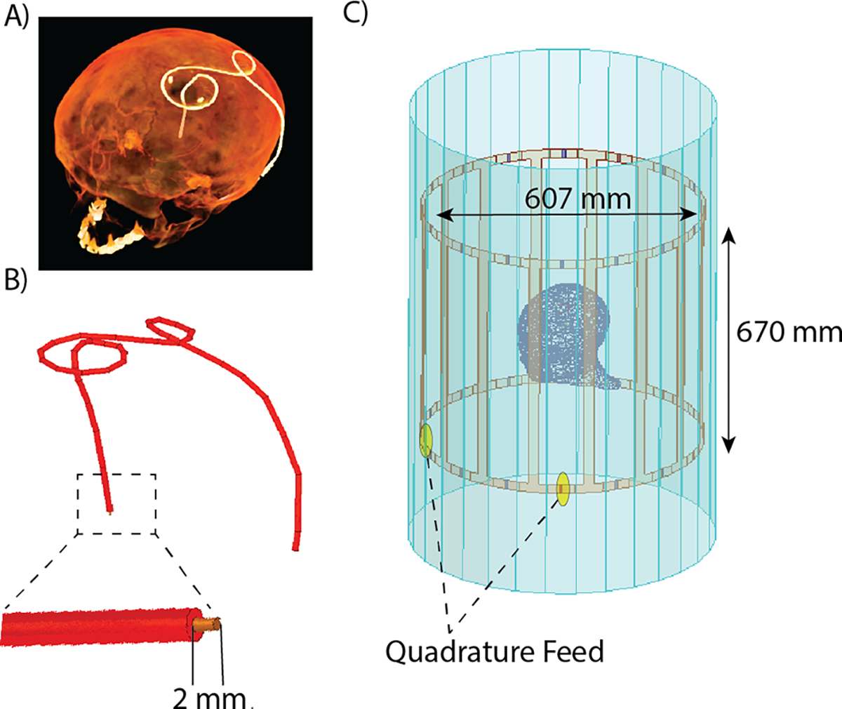
(A) Preprocessing pipeline for DBS lead segmentation from patient CT images and (B) reconstruction of DBS lead trajectories. (C) Lead model implanted in a homogenous head phantom exposed to the RF field from an RF birdcage body coil for electromagnetic simulations.
Figure 2.
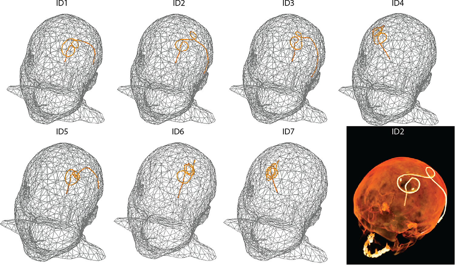
Models of homogeneous heads with reconstructed, isolated wires shaped to patient-derived DBS lead trajectories (patients ID1-ID7) for electromagnetic and thermal simulations. An example CT image is included for patient ID2.
Temperature rise was calculated during 254 seconds of RF exposure using the transient thermal solver of ANSYS Mechanical. Pennes’ bioheat equation was solved without perfusion, with the specific heat capacity of tissue equal to 4150 J(kg −1 C−1), the density of tissue equal to 1000 kg/m3, and the isotropic thermal conductivity of tissue equal to 0.42 W/m−1 C−1. To calibrate the input power of the coil, we adjusted the voltage input to the coil, such that the calculated and measured temperatures were the same for one patient (ID4). To do this, we calculated the temperature rise at three different locations of tissue in immediate contact with the exposed region of the wire to mimic the region of temperature measurements conducted by the fluoroptic temperature probes used during the experiments (Figure 3). The average temperature rise from these three locations was calculated and used to calibrate the coil’s input voltage. After calibration, we applied the same voltage to the remaining simulated coil models. For each patient model, the temperature rise at the tip was calculated as previously described, using the average temperature rise of the three points around the tip of the wire.
Figure 3.
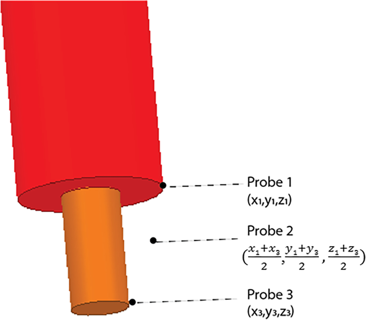
Location of temperature probes for determining temperature rise during thermal simulations. The temperature rise was calculated at these three points and then averaged.
B. Experiments
To evaluate the calculated temperature increase at the tips of implanted wires with different trajectories, phantom experiments were performed at a Siemens Aera 1.5 T scanner (Siemens Healthineers, Erlangen, Germany). An insulated copper wire (diameter of conductor = 1 mm, diameter of insulator = 2.5 mm) with a length of 40 cm and a 2 mm exposed tip was shaped to match each patient-derived lead trajectory. To do this, models of the lead trajectories were 3D printed with ABS plastic (diameter = 3 mm) to serve as guides for wire shaping (Figure 4). An agar-based NaCl solution was used to create a homogeneous anthropomorphic gel head phantom with conductivity and relative permittivity ( ) values representative of biological tissue. Shaped wires were inserted into the phantom following the entry point and angle of penetration similar to simulated models. RF exposure was performed using a T1-weighted turbo spin echo (TSE) sequence (TR= 814 ms, TE = 7.3 ms, FA = 150°, B1+rms = 4.15 μT, slice thickness = 1.4 mm, resolution = 0.9×0.9×1.4 mm3). Fluoroptic temperature probes (OSENA, BC, Canada) were securely attached to the wires at the exposed tips to measure the temperature rise at the tips. Probes were allowed ample cooling time in between measurements of different lead trajectories. Maximum temperature increase at the tip of the implanted wire was measured during 254 seconds of RF exposure for each lead trajectory.
Figure 4.
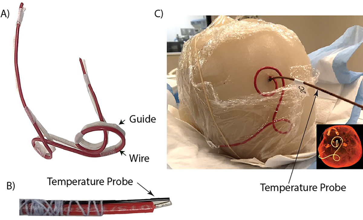
(A) Generic wire (red) used during experiments shaped to a 3D-printed DBS lead trajectory guide (white) of patient ID2. (B) Fluoroptic probe securely attached to the tip of the generic wire for temperature measurements. (C) Wire and fluoroptic probe were implanted into the anthropomorphic gel head phantom for imaging at 1.5 T. CT image included for comparison between the patient-derived DBS lead trajectory and the trajectory of the implanted wire.
III. RESULTS
Temperature rise, , was experimentally measured and numerically simulated for implanted wires mimicking DBS leads of varying patient-derived trajectories. A substantial variation was observed in as a function of lead trajectory; there was a 9.5-fold and 9-fold increase in temperature rise from ID1 to ID7 during simulations and experimental measurements, respectively. From simulations, the temperature rise at the tip of the wire ranged from 0.648 °C to 0.032 °C. The temperature rise at the tip of the wire observed during experiments was 0.66 °C to 0.07 °C. The lead trajectory from patient ID1 had the largest temperature rise from both simulations and measurements (Figure 5). Conversely, the lead trajectory from patient ID7 produced minimal RF heating, as observed in both simulations and measurements (Figure 5). Figure 6 shows the heating profile generated from thermal simulation following RF exposure for patient ID2; maximum temperature rise was localized at the region of tissue immediately surrounding the tip of the wire.
Figure 5.
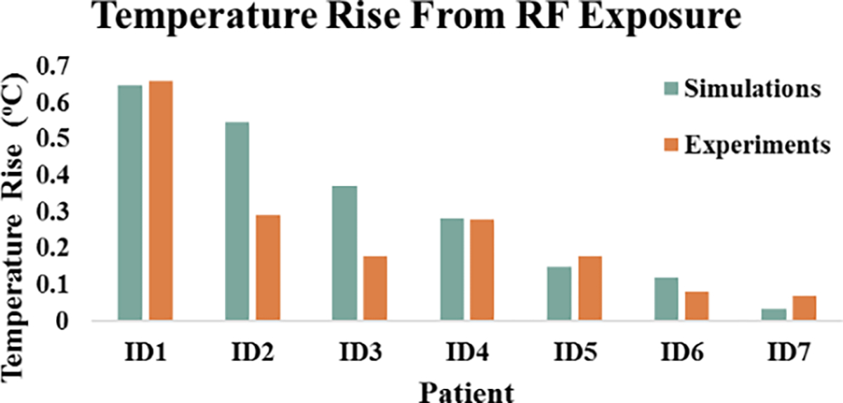
Temperature rise for each patient-derived DBS trajectory from numerical simulations and experimental measurements.
Figure 6.
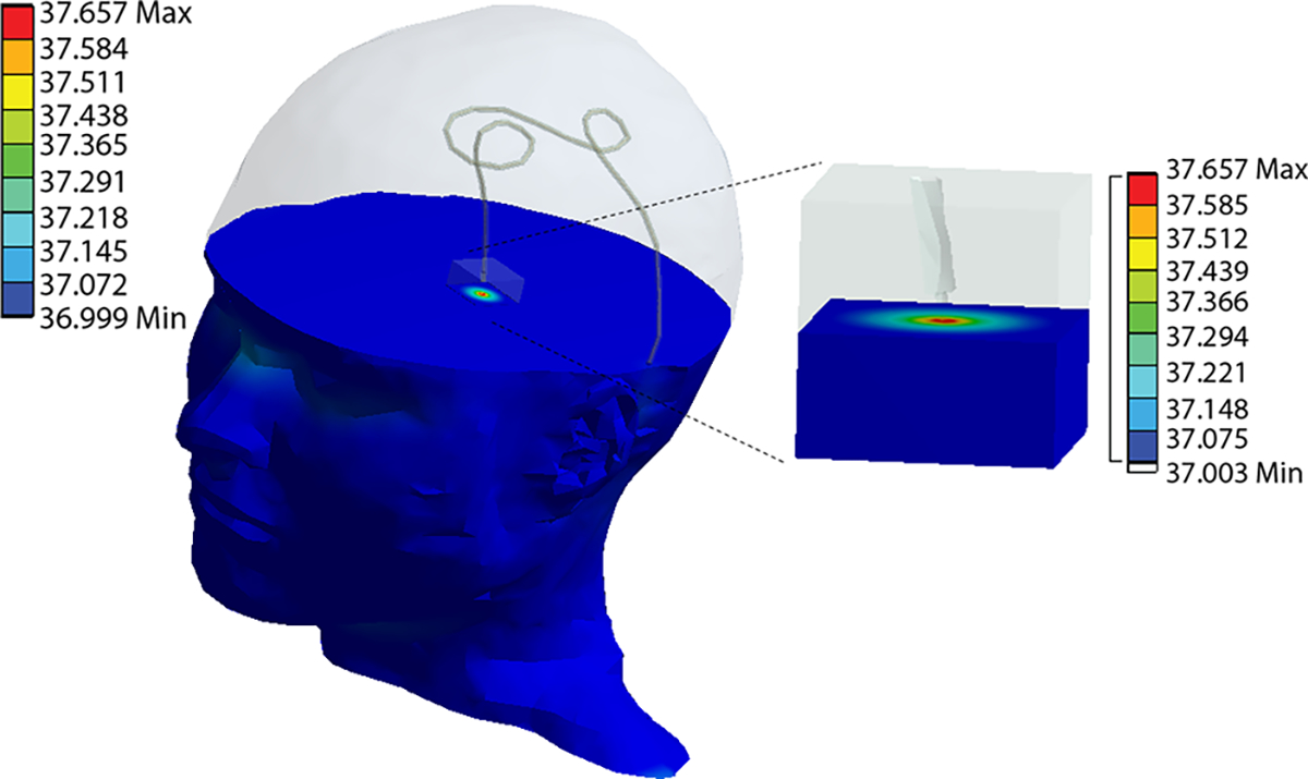
Heating profile from thermal simulation displaying temperature rise occurring in tissue surrounding the tip of the wire for patient ID2.
Despite the large range of observed temperatures, we found a strong correlation between measured and simulated (r2 = 0.74). The maximum difference between simulated and measured temperature was 0.26 °C with simulations overestimating the temperature rise.
IV. DISCUSSION
This work presents an evaluation study to compare RF-induced heating at the tip of wires with realistic, patient-derived DBS lead trajectories using thermal simulations and experimental measurements during phantom imaging. There have been continual efforts to mitigate concerns with RF heating to improve patient safety. Surgical management of DBS lead trajectories is shown to be advantageous for reducing RF-induced heating at the tips of DBS leads [3–4]. The technique works by optimizing the extracranial trajectory of implanted leads such that its coupling with MR scanner electric fields is minimized. However, determination of optimal lead trajectories through experiments is a lengthy process. Numerical simulations, once validated, can significantly shorten the optimization process. The effects of lead trajectories were incorporated in this study, and temperature rise from the patient-derived lead trajectories were consistent with the expected heating predicted by simulations
Several simplifications were applied to our simulation models and experimental setup. Models of DBS leads trajectories for both simulations and experimental measurements consisted of isolated cases; thus, further investigation is necessary to compare these two methods for assessing RF heating of complete DBS systems, inclusive of the extension cables and implanted pulse generator (IPG). Computational head models were homogenous to allow for replication of the phantom constructed for imaging. However, the effects of heterogeneous head models on temperature rise can be further investigated. Specific body compositions can also alter RF heating as electrical conductivities and MRI electric field distribution vary widely across different body tissues. Additionally, EM simulations were performed with a generic RF transmit body coil, which may introduce some discrepancies when comparing to the actual commercial transmit coil used during scanning.
V. CONCLUSION
In this study, we demonstrate that numerical simulations can model and predict heating of tissue at the tips of wires upon RF exposure. Heating profiles from simulations demonstrate that simulations were able to accurately model tissue heating phenomena for varying DBS lead trajectories, given the strong correlation between simulated and measured temperatures. This work addresses needed validation of temperature rise from simulations as simulations are becoming more prevalent for studying RF heating of conductive implants subjected to MRI environments.
Acknowledgments
Research supported by National Institute of Health grants R00EB021320 and R03EB025344.
Contributor Information
Jasmine Vu, Department of Biomedical Engineering and Department of Radiology, Northwestern University, Chicago, IL 60611 USA..
Bhumi Bhusal, Department of Radiology, Northwestern University, Chicago, IL 60611 USA..
Bach T. Nguyen, Department of Radiology, Northwestern University, Chicago, IL 60611 USA.
Laleh Golestanirad, Department of Biomedical Engineering and Department of Radiology, Northwestern University, Chicago, IL 60611 USA..
REFERENCES
- [1].Rezai AR et al. , “Neurostimulation System Used for Deep Brain Stimulation (DBS): MR Safety Issues and Implications of Failing to Follow Safety Recommendations,” Invest. Radiol, vol. 39, no. 5, pp. 300–303, 2004, doi: 10.1097/01.rli.0000124940.02340.ab. [DOI] [PubMed] [Google Scholar]
- [2].Rezai AR et al. , “Neurostimulation systems for deep brain stimulation: In vitro evaluation of magnetic resonance imaging-related heating at 1.5 Tesla,” J. Magn. Reson. Imaging, vol. 15, no. 3, pp. 241–250, Mar. 2002, doi: 10.1002/jmri.10069. [DOI] [PubMed] [Google Scholar]
- [3].Golestanirad L, Angelone LM, Iacono MI, Katnani H, Wald LL, and Bonmassar G, “Local SAR near deep brain stimulation (DBS) electrodes at 64 and 127 MHz: A simulation study of the effect of extracranial loops,” Magn. Reson. Med, vol. 78, no. 4, pp. 1558–1565, 2017, doi: 10.1002/mrm.26535. [DOI] [PMC free article] [PubMed] [Google Scholar]
- [4].Golestanirad L et al. , “RF-induced heating in tissue near bilateral DBS implants during MRI at 1.5 T and 3T: The role of surgical lead management,” Neuroimage, vol. 184, pp. 566–576, Jan. 2019, doi: 10.1016/J.NEUROIMAGE.2018.09.034. [DOI] [PMC free article] [PubMed] [Google Scholar]
- [5].Neufeld E, Kühn S, Szekely G, and Kuster N, “Measurement, simulation and uncertainty assessment of implant heating during MRI,” Phys. Med. Biol, vol. 54, no. 13, pp. 4151–4169, 2009, doi: 10.1088/0031-9155/54/13/012. [DOI] [PubMed] [Google Scholar]
- [6].Guo R et al. , “Computational and experimental investigation of RF-induced heating for multiple orthopedic implants,” Magn. Reson. Med, vol. 82, no. 5, pp. 1848–1858, 2019, doi: 10.1002/mrm.27817. [DOI] [PubMed] [Google Scholar]
- [7].Fujimoto K, Angelone LM, Lucano E, Rajan SS, and Iacono MI, “Radio-frequency safety assessment of stents in blood vessels during magnetic resonance imaging,” Front. Physiol, vol. 9, no. OCT, pp. 1–10, 2018, doi: 10.3389/fphys.2018.01439. [DOI] [PMC free article] [PubMed] [Google Scholar]
- [8].Golestanirad L et al. , “RF heating of deep brain stimulation implants in open-bore vertical MRI systems: A simulation study with realistic device configurations,” Magn. Reson. Med, no. May, pp. 1–9, 2019, doi: 10.1002/mrm.28049. [DOI] [PMC free article] [PubMed] [Google Scholar]
- [9].Golestanirad L et al. , “Construction and modeling of a reconfigurable MRI coil for lowering SAR in patients with deep brain stimulation implants HHS Public Access,” Neuroimage, vol. 147, pp. 577–588, 2017, doi: 10.1016/j.neuroimage.2016.12.056. [DOI] [PMC free article] [PubMed] [Google Scholar]
- [10].McElcheran CE et al. , “Numerical Simulations of Realistic Lead Trajectories and an Experimental Verification Support the Efficacy of Parallel Radiofrequency Transmission to Reduce Heating of Deep Brain Stimulation Implants during MRI,” Sci. Rep, vol. 9, no. 1, Dec. 2019, doi: 10.1038/s41598-018-38099-w. [DOI] [PMC free article] [PubMed] [Google Scholar]
- [11].Kazemivalipour E et al. , “Reconfigurable MRI technology for low-SAR imaging of deep brain stimulation at 3T: Application in bilateral leads, fully-implanted systems, and surgically modified lead trajectories,” 2019, doi: 10.1016/j.neuroimage.2019.05.015. [DOI] [PMC free article] [PubMed] [Google Scholar]
- [12].Golestanirad L et al. , “Reconfigurable MRI coil technology can substantially reduce RF heating of deep brain stimulation implants: First in-vitro study of RF heating reduction in bilateral DBS leads at 1.5 T,” PLoS One, vol. 14, no. 8, 2019, doi: 10.1371/journal.pone.0220043. [DOI] [PMC free article] [PubMed] [Google Scholar]
- [13].McElcheran CE, Yang B, Anderson KJT, Golestanirad L, and Graham SJ, “Parallel radiofrequency transmission at 3 tesla to improve safety in bilateral implanted wires in a heterogeneous model,” Magn. Reson. Med, vol. 78, no. 6, pp. 2406–2415, Dec. 2017, doi: 10.1002/mrm.26622. [DOI] [PubMed] [Google Scholar]
- [14].McElcheran CE, Yang B, Anderson KJT, Golenstani-Rad L, and Graham SJ, “Investigation of Parallel Radiofrequency Transmission for the Reduction of Heating in Long Conductive Leads in 3 Tesla Magnetic Resonance Imaging,” PLoS One, vol. 10, no. 8, p. e0134379, Aug. 2015, doi: 10.1371/journal.pone.0134379. [DOI] [PMC free article] [PubMed] [Google Scholar]
- [15].Golestanirad L et al. , “Reducing RF-Induced Heating Near Implanted Leads Through High-Dielectric Capacitive Bleeding of Current (CBLOC),” IEEE Trans. Microw. Theory Tech, vol. 67, no. 3, pp. 1265–1273, Mar. 2019, doi: 10.1109/TMTT.2018.2885517. [DOI] [PMC free article] [PubMed] [Google Scholar]


