Abstract
One of the most common types of 3D printing technologies is inkjet printing due to its numerous advantages, including low cost, programmability, high resolution, throughput, and speed. Inkjet printers are also capable of fabricating artificial tissues with physiological characteristics similar to those of living tissues. These artificial tissues are used for disease modeling, drug discovery, drug screening, and replacements for diseased or damaged tissues. This paper reviews recent advancements in one of the most common 3D printing technologies, inkjet dispensing. We briefly consider common printing techniques, including fused deposition modeling (FDM), stereolithography (STL), and inkjet printing. We briefly discuss various steps in inkjet printing, including droplet generation, droplet ejection, interaction of droplets on substrates, drying, and solidification. We also discuss various parameters that affect the printing process, including ink properties (e.g., viscosity and surface tension), physical parameters (e.g., internal diameter of printheads), and actuation mechanisms (e.g., piezoelectric actuation and thermal actuation). Through better understanding of common 3D printing technologies and the parameters that influence the printing processes, new types of artificial tissues, disease models, and structures for drug discovery and drug screening may be prepared. This review considers future directions in inkjet printing research that are focused on enhancing the resolution, printability, and uniformity of printed structures.
I. INTRODUCTION
3D printing technology is a promising additive manufacturing method for the fabrication of patient-specific constructs with many applications in healthcare and medicine, such as oral medications,1–5 drug discovery, drug screening, drug delivery,6–8 regenerative medicine, tissue engineering,3,4,9–12 cancer studies,3,13–18 and disease modeling.3,8,11,19–21 It was invented by Zoltan, Kyser, and Sears independently around 30 years ago.22–24 This paper considers recent advances in the field of 3D printing technology for biomedical and pharmaceutical applications from an engineering viewpoint. Readers may consult with the other published review papers on the topic 1,5,7–9,12,14,25,26 to become more familiar with the medical and biological aspects of this cutting-edge technology. In this paper, we consider the mechanisms and governing effects of inkjet printers designed and developed in the past 10 years. This type of printer is the most common one used in healthcare applications. The printing mechanisms along with engineering characteristics such as fluid type, dimension, actuator, constitutive material, and accuracy of the printer are considered. Although we examine the prototypes and experimental equipment associated with this technology, some important pioneering theoretical and computational studies on the topic will also be briefly considered to gain a better understanding of the underlying inkjet printing process.
In Secs. II–IV, we will briefly introduce various classes of 3D printing technology and review some of the most important biomedical applications of this technology. Section IV will focus on inkjet printing. We will briefly introduce various steps in inkjet printing technology and will review the research projects associated with each of these steps. We will also consider the advantages and disadvantages of this technology and discuss design parameters of inkjet printers, including properties of inks, nozzles, actuators, droplet size, and resolution. In Sec. VI, we will summarize some engineering restrictions of the 3D printers and the further development of this technology.
3D printing technologies have recently revolutionized many healthcare and medical industries. The ability to create analogous constructs of the living tissues makes this technology appealing for many healthcare and medical applications.27 One of the main applications of 3D printers is in the pharmaceutical industry. 3D printers have the capability for constructing high-throughput8 and low-cost constructs for drug discovery,7 drug screening,11 and drug delivery.25 The other application of the bioprinters is printing organ-on-a-chip, which is considered a high-tech method. Organ-on-a-chip devices are 3D microfluidic cell culture chips that simulate the activities, mechanics, and physiological response of entire organs and organ systems. These microfluidic devices have many applications in cancer research, disease modeling, and pharmaceutical studies. Several types of organ-on-a-chip structures have been developed,28 such as heart-on-a-chip,29 kidney-on-a-chip,30 and liver-on-a-chip structures.31 Bioprinting enables the printing of multiple types of materials, including biocompatible materials and live cells. This approach can be used to create organ-on-a-chip platforms for drug discovery and disease modeling.32 3D printers have also been successfully used to create artificial skin for different applications such as grafting, wound healing,33,34 and personalized cancer therapy.35–37 One of the other biomedical applications of this technology is bone regeneration. This technology can be used to construct bone tissue for grafts,38,39 scaffolds,40 and implants.41,42 This technique can be used for reconstructing bone at the site of skull defects, which can be caused by surgical treatments of skull tumors 43,44 or surgical procedures45,46 (e.g., craniectomy).47
In dentistry, 3D printing is used to create many types of oral and facial prostheses such as removable dentures for edentulous patients,48 fixed prostheses such as crowns and bridges,2 and obturators for patients with cleft palate.49 The use of 3D printing in dentistry decreases chair time, reduces the cost of prosthesis fabrication, and helps patients to become more involved in treatment procedures. This technique is also applied in the orthodontic treatment of minor teeth crowding.50,51 Fabrication of surgical stent guides is another application of 3D printing in dentistry.52 Endodontists can implement this approach for endodontic procedures such as guided endodontic access and guided endodontic surgery.53 In cardiovascular science, this technology can be used to regenerate functional heart valves21,54–58 This technology has also been used successfully to construct other tissues, such as liver,59,60 lung,61–63 kidney,64–66 prostate,60 and blood vessels.67–69 Each type of bioprinter has its own advantages and disadvantages, which are mentioned in Secs. II–IV.
II. FUSED DEPOSITION MODELING (FDM)
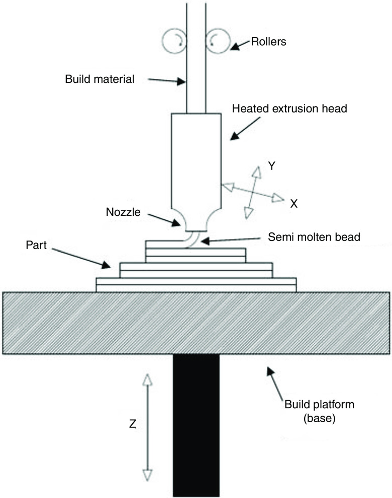
Figure 1 shows the printing mechanisms of fused deposition modeling (FDM) 3D printing. In these printers, an extruded polymer filament goes through a heated nozzle and becomes softer when heated; the filament material will then be deposited in a layer-by-layer manner on a plate to form the desired feature. In the FDM technique, the extruder speed, layer height, nozzle temperature, and plate temperature have significant effects on the printer function.70,71 The standard speed of the printing is 90 mm/s, which results in a 100 to 400 deposit thickness layer.25 Thermoplastic polymers are commonly used to create FDM filaments; these materials exhibit low melting points for printing as well as low mechanical strength values when extruded.72 Polylactic acid (PVA) and acrylonitrile butadiene styrene (ABS) are the most common polymers used in FDM printers.25,73 The fused deposition modeling technique is the most promising one for the fabrication of unit dose drug carriers. Furthermore, fused deposition modeling is a rapid prototyping technology with the ability to produce scaffolds with fully interconnected channel networks as well as control over porosity and channel size.74
FIG. 1.
Diagram of fused deposition modeling. Reprinted with permission from Chohan et al., Composites Part B: Engineer. 117, 138–149 (2017).186 Copyright 2017 Elsevier.
Extrusion bioprinting is based on dispensing hydrogels, other polymers, cells, and matrix materials through micronozzles. This technique is able to fabricate the constructs with complex geometries containing various cells. Commercialized versions of this printer are available.75 The use of sol-gel materials, hydrogels, and reversible gels in FDM is discussed elsewhere.76 The design of these printers can be readily modified.77
III. STEREOLITHOGRAPHY (STL)
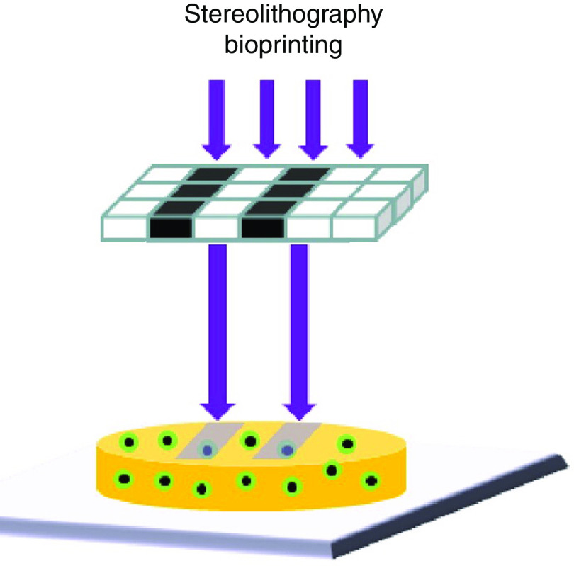
Figure 2 shows a schematic of STL printing technology. In this technology, the liquid resin will be photopolymerized, or solidified, in a layer-by-layer manner in a single-photon or multi-photon approach to print a solid object. Light from a lamp is directed on a specific portion of a layer of a vat, which results in polymerization of the resin in that portion of the vat.78 The photons used in this approach can include visible light, ultraviolet light, and infrared light. However, ultraviolet light may be harmful to living cells. This problem has been addressed by using a new type of visible light crosslinkable polymer.79 This technique has been implemented using direct light assisted writing, physical mask projection, or digital mask projection approaches.80 These printers are usually categorized as high-resolution 3D printers; the resolution is restricted by the light source, optics, and polymerization approach. Furthermore, it is an efficient technique for patterning multiple cell types since the STL direct-write approach does not prevent proliferation of cells.81 This technique is suitable for fabricating objects with precise microscale features.73,82 A number of polymers have been used in STL printing such as PEGDA,83,84 poly(2-hydroxyethyl methacrylate) (pHEMA),85 poly(ethylene glycol) dimethacrylate (PEGDMA),86,87 and poly(propylene fumarate)/diethyl fumarate (PPF/DEF).88 The main drawback is the relatively low number of photocrosslinkable polymers that are compatible with this technique. Two photon stereolithography (TPS) can be used to print 3D structures with microscale and sub-microscale features out of polymer and inorganic-organic hybrid (e.g., Ormocer®) materials. The two photon stereolithography process involves multiphoton absorption by photoinitiator molecules, which leads to photopolymerization of material within well-defined and highly localized volumes. The absorption of laser pulses is used to generate free radicals from photoinitiator molecules. The radicalized molecules cause polymerization of the material within a small focal volume. A three-dimensional structure is obtained by polymerizing the material along the laser trace, which is moved in three dimensions with a micropositioning apparatus. One limitation of two photon stereolithography is slow processing rates.89,90 Stereolithography over large areas and at faster rates can be obtained through the use of a digital mirror device (DMD); in dynamic optical projection stereolithography, the UV or visible light interacts with the DMD mirror, which produces an optical pattern as directed by a computer design. The projected light, after passing the optical lens, will interact with a photosensitive material to solidify a layer of the 3D structure.91–93 The advantages of the stereolithography approach include the ability to create structures with a wide variety of geometries and dimensions.94
FIG. 2.
Schematic of stereolithographic printing. Reprinted with permission from Mandrycky et al., Biotech. Adv. 34(4), 422–434 (2016).12,187 Copyright 2016 Elsevier.
IV. INKJET PRINTERS
Inkjet printing refers to a class of the additive manufacturing technologies for reproducing images or characters on a substrate from digital data; this process involves precisely ejecting and steering inks as droplets to predefined positions on the substrate. The droplets are usually transferred to the receiving substrate from the printhead in a non-contact manner by different mechanisms such as gravity, hydrostatic pressure, as well as piezoelectric, electrical, and thermal actuators. Inkjet-based printing technologies offer many advantages such as compatibility with biological materials, low cost, programmability, high resolution, high throughput, and high speed. The first study that examined the biomedical application of inkjet printing was reported by Klebe in 1988;95 he used the HP inkjet printers to produce 2D and 3D synthetic tissues by depositing collagen and fibronectin. Since then, several studies have examined biomedical applications of inkjet printers in the fields of regenerative medicine,4,96 toxicology,8 disease modeling,20 and pharmaceutical science.25,97,98 Michael Cima and his team are one of the pioneers of a 3D printing process based on inkjet printing; they fabricated ceramic parts using sub micrometer powders containing alumina and silicon nitride. Ceramic slurry was used for the sequential layering process; inkjet printing of a binder system was applied to these layers.99–101
The inkjet printing mechanism consists of three main steps: (1) fluid ejection and droplet generation, (2) positioning and interaction of the droplets on the substrates, and (3) drying and solidification of the printed features to produce a solid deposit. Inkjet printers are usually classified based on the mechanism of generating droplets into two main categories: continuous inkjet printing (CIJ) and drop-on-demand (DOD) printing. In the 19th century, Raleigh showed that a stream of fluid naturally tends to break into a stream of drops because of surface tension forces.102,103 The CIJ printers exploit this effect to produce charged droplets from the ejected stream of liquid. In this type of inkjet printer, the stream of liquid is continuously ejected from the printhead by applying a continuous hydrostatic pressure, even if printing is not required. The stream of liquid then breaks down into the stream of droplets due to the surface tension forces. To form the desired patterns, the unwanted droplets are manipulated by the electric field and collected by a gutter. Therefore, the CIJ printing technology can be a wasteful process. However, this technology is widely used in industrial applications due to its high-speed capabilities.102
The DOD printers directly eject the inks from the printheads in the form of droplets onto the substrates by various mechanisms such as thermal, electrical, and piezoelectric actuators. Fluid ejection and droplet generation do not occur simultaneously in the DOD printers. Unlike CIJ printers, the DOD printers generate individual drops when required; as such, they are less wasteful and more economical compared with CIJ printers. The DOD printers are dominant in the pharmaceutical and biomedical industries. Based on the droplet generating mechanism, the DOD inkjet printers are classified into three main groups: thermal inkjet printers, piezoelectric inkjet printers, and electrohydrodynamic inkjet printers.
The printing steps are highly affected by the inertial, viscous, gravitational, and surface tension forces; the kinetic and surface energies also play important roles. These forces are highly affected by geometrical, fluidic, and flow properties, including density ( ), dynamic viscosity ( ), kinetic viscosity ( ), surface tension of fluid ( ), flow field velocity ( ), and characteristic length ( ). To obtain a better understanding of these processes, dimensionless numbers have been defined to show the relative strength of various phenomena and explain the behavior of fluids. Table I summarizes these dimensionless numbers. The advantages of inkjet printers include low cost, programmability, high resolution, high speed, and biocompatibility. High pressure or heat associated with thermal inkjet printing can be harmful for living cells.24
TABLE I.
Important non-dimensional numbers in the inkjet printing process.
| Non-dimensional number | Definition | Physical Meaning |
|---|---|---|
| Reynolds number ( ) | ||
| Weber number ( ) | ||
| Ohnesorge number ( ) | ||
| Bond number ( ) |
V. FLUID EJECTION AND DROPLET GENERATION
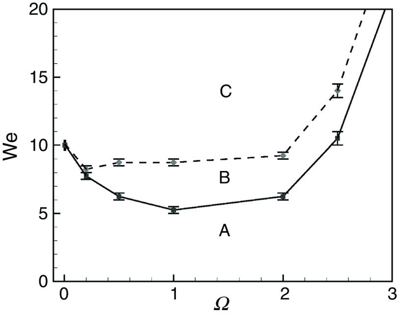
Droplet generation in DOD printing technologies depends on momentum, viscosity, and surface tension. The Reynolds, Weber, and Ohnesorge numbers are used to understand the printability and the droplet formation of DOD printers. Recent papers have considered droplet formation and important printing factors.104–106 Several experimental and numerical studies have been performed to understand the influences of various parameters on droplet formation and ejection in DOD technologies. Although recent studies on this topic are mainly experimental, we have briefly reviewed significant numerical studies that provide a fundamental understanding of the theory associated with DOD inkjet printing technology. As an example, Xu and Basaran computationally simulated the formation of the liquid droplets in piezoelectric DOD printers.24 They assumed an incompressible flow of the Newtonian fluid (ink) in a simple capillary tube. They modeled the oscillatory flow field in the tube with the frequency of ; they considered the influence of piezoelectric actuation on the flow field, and characterized droplet formation based on the Weber and Ohnesorge numbers. Their computational results show that for the Ohnesorge number of 0.1 ( ), the Weber number regulates droplet ejection in DOD inkjet printers (Fig. 3). If the Weber number is low, the generated droplet does not break up, remains suspended, and periodically oscillates at the tip of the nozzle (region A). For region B, the inertia force will be strong enough to eject the droplets from the nozzle. However, the velocity at the tip of the ejected droplets will be negative; consequently, the droplets will move toward the nozzle upon breakup, which is an undesirable phenomenon. The desired DOD drop formation mechanism will occur for the frequency and the Weber number associated with region C; in this region, the inertia force will be strong enough to eject the DOD drop with a positive velocity at the tip. Here, we should mention that the results and characteristic diagrams were all based on a nozzle with radius (Ohnesorge number of 0.1). However, recent advancements in DOD printing technologies may result in the development of the printers with smaller nozzle diameters. Although this diagram can be modified for the other nozzle diameters and Ohnesorge numbers, it gives the reader a good estimation of the frequency range and Weber number associated with stable droplet ejection.
FIG. 3.
Phase diagram when Oh = 0.1. The drop will not be generated in regime A. The drop will be generated in regime B, but the velocity of the tip at breakup is negative. A drop will be generated with positive velocity at the tip at breakup when the Weber number and frequency are in regime C. Reproduced from Xu and Basaran, Phys. Fluids 19(10), 102111 (2007),24 with the permission of AIP Publishing.
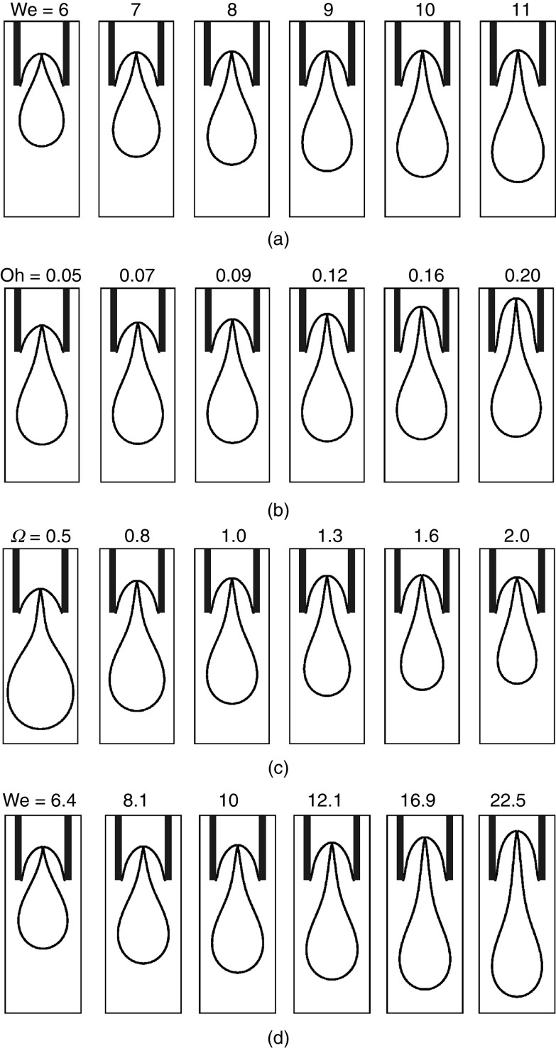
For the region of droplet generation (region C), the effects of the Weber number, the Ohnesorge number, and frequency on droplet generation and ejection were evaluated. Figure 4 shows how the droplets are developed and ejected for different values of these parameters. Figure 4(a) shows that the maximum injected volume increases by the Weber number when the frequency is kept constant. Figure 4(b) illustrates that an increase in the Ohnesorge number will reduce the limiting length and the drop volume; the breakup time will increase slightly. Figure 4(c) shows that an increase in frequency causes a decrease in the maximum injected volume. Figure 4(d) indicates that the drop length at the breakup increases along with the Weber number.
FIG. 4.
Effect of Weber and Ohnesorge numbers and frequency on drop shape at breakup time: (a) Oh = 0.1, =1, (b) We = 10, =1, (c) Oh = 0.1, We = 10, and (d) Oh = 0.1, = . We and varied together in a situation in which the maximum amount of injected volume is kept constant at . Reproduced from Xu and Basaran, Phys. Fluids 19 (10), 102111 (2007),24 with the permission of AIP Publishing.
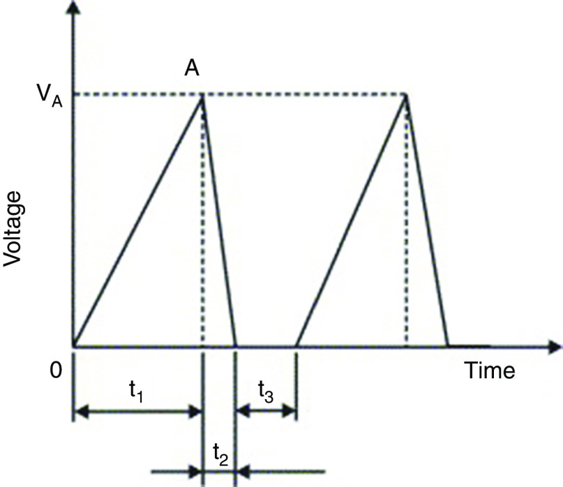
Chen et al. investigated the influences of various design parameters (e.g., the nozzle diameter and the chamber dimension) and the driving conditions on the droplet generation and ejection (volume and velocity) in piezoelectric DOD printers.107 They define the volume factor ( ) as a decisive parameter in piezoelectric DOD printers. In this equation, is the nozzle diameter and is the driving volume change in the chamber due to the piezoelectric actuator displacement. This parameter can be used to define practical values associated with droplet generation. They assumed a typical triangle electrical waveform for driving the piezoelectric actuator (Fig. 5) and showed that a shorter driving time of the piezoelectric actuator ( ) will result in a faster driving velocity of the droplet ( ). They proposed the following empirical formula to show how the driving velocity of the droplet is related to the driving time of the piezoelectric actuator:
| (1) |
FIG. 5.
Typical electrical waveform for a driving piezoelectric in which is suction time, is driving time, and is resting or dwell time. Reprinted with permission from Chen et al., Int. J. Mech. Sci. 49(6), 733–740 (2007).107 Copyright 2007 Elsevier.
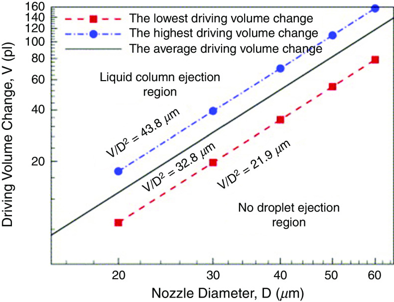
The results also confirmed that the geometry of the nozzle has a negligible effect on the droplet characteristics when the ratio of the nozzle plate thickness ( to the nozzle diameter ( is greater than 1 ( ). Figure 6(a) classifies the range of the driving volume change ( and the droplet diameter ( ) into three regions, namely “no droplet ejection,” “droplet ejection,” and “column ejection.” This figure is based on . The results also showed that for different values of the nozzle diameter, the same values of the volume factor ( ) resulted in the same ejection velocities of the droplet.
FIG. 6.
Volume change vs nozzle diameter when the diameters are between 20 and 60 at . Reprinted with permission from Chen et al., Int. J. Mech. Sci. 49(6), 733–740 (2007).107 Copyright 2007 Elsevier.
They proposed two empirical equations to describe the design of piezoelectric-actuated droplet generation:
| (2) |
| (3) |
The first empirical formula shows that the droplet velocity ( ) is linear with respect to the volume factor ( ) with a slope of 0.3422. The second formula can be used to find the driving volume of the piezoelectric actuator ( ) and the nozzle diameter ( ) in order to eject droplets with the desired volume of .
Shin et al. aimed to find a semi-analytical method to decrease the computational cost of simulating the mass transport rate in piezoelectric DOD inkjet printers.108 They assumed that fluid flow inside the tube is axisymmetric and laminar, and obtained a simplified 1D finite difference model to simulate the jet profile and droplet generation. Dadvand et al. developed a computational model based on the Eulerian-Lagrangian and boundary integral equation method to investigate spark bubble-generated droplet behavior. They examined axisymmetric droplet generation and ejection through a circular hole, as well as the hole at the top of a vertical cylinder. A bubble may form after ignition, which generates pressure waves with nonsymmetrical features; these pressure waves may allow a droplet that is smaller than the aperture to form and then disintegrate.109
Cheng and Chiu investigated the effects of the nozzle diameter, the viscosity coefficient, and the surface tension of ink on the droplet formation.110 Their results showed that the smallest nozzle diameter had the fastest replenishing process, since it required the lowest amount of liquid. On the other hand, a larger period of replenishment was associated with printers containing larger nozzle diameters. The diameter of the nozzle also affected the speed of the droplets. The smaller nozzle diameters were associated with higher ink speeds. This study showed that the speed of water and ink droplets were similar. The viscosity coefficient and the surface tension of the ink used in this study was almost the same as water. By keeping the viscosity coefficient constant, an increase in the surface tension enhanced the speed of the ejected droplet. However, this finding may not be valid for the very small viscosity coefficients. For the same value of the surface tension, an increase in the viscosity enhanced the volume and reduced the speed of the ejected droplets.
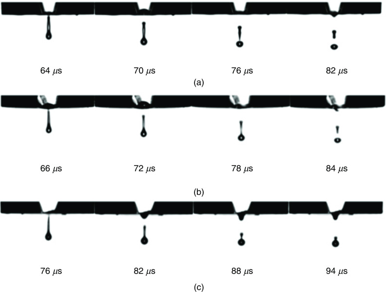
Jo et al. evaluated the effect of viscosity (1.0–11 cp) on jet stability for DOD inkjet printing with comparable surface tension values. Figure 7 shows how the fluid viscosity affects jet behavior and droplet ejection.111 In piezoelectric inkjet printing, the electric pulses periodically deform the piezoceramic plate, which generates an acoustic wave. The resonance amplifies the wave and releases the liquid out of the nozzle. The results showed that there is a maximum stable frequency, which is called critical frequency; there are no significant changes in the jet speed for various viscous liquids below this critical frequency. They showed that the more viscous liquid was more stable at higher frequencies. In turn, higher viscosity fluids were able to eliminate the remaining energy of the wave pulse in the nozzle through energy dissipation. They have also shown that slower capillary wave propagation increased the breakup time of the jet.
FIG. 7.
Behavior of jets for fluids with different viscosity (a) glycerol 20 wt. %, (b) glycerol 40 wt. %, and (c): glycerol 60 wt. %. Reprinted with permission from Jo et al., Korean J. Chem. Engineer. 26(2), 339–348 (2009).111 Copyright 2009 Springer Nature.
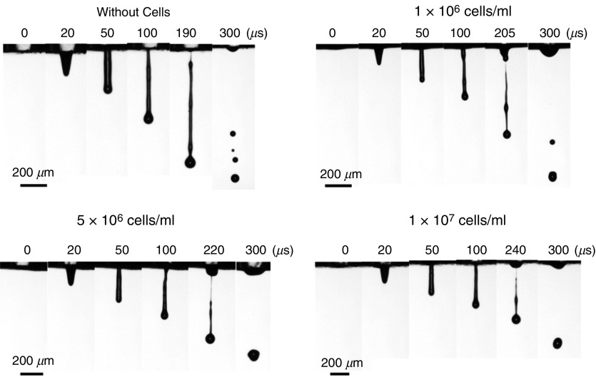
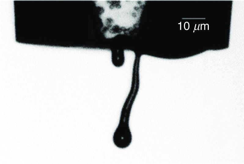
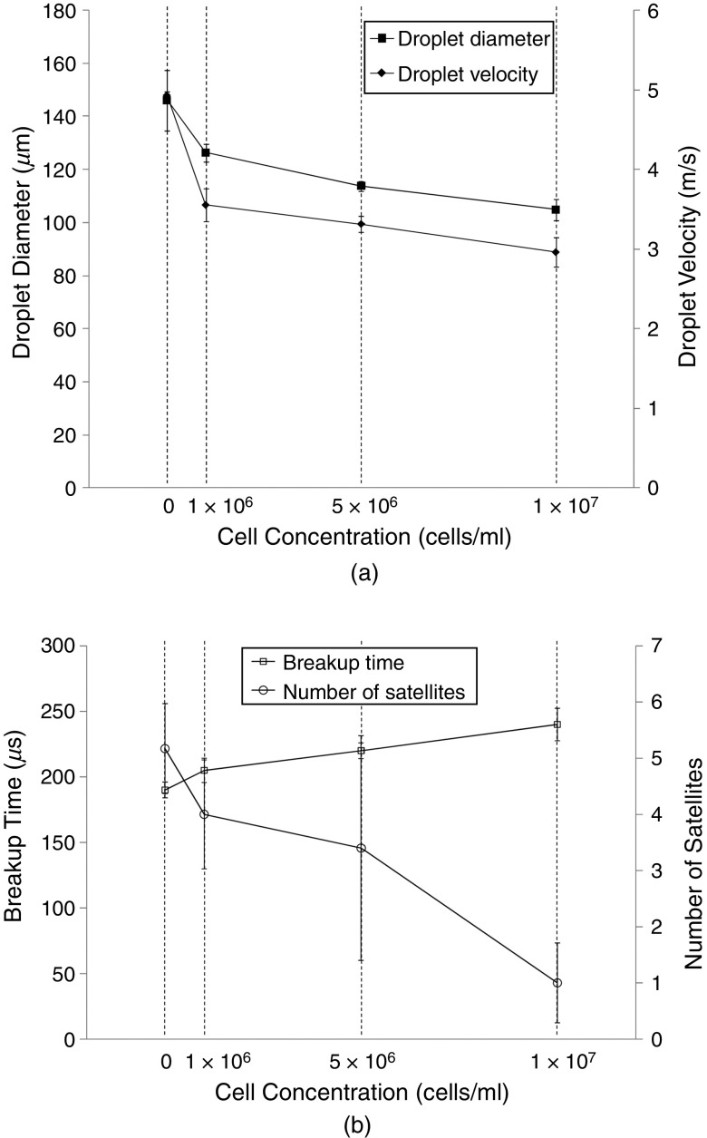
The effect of airflow created by the printing head-media movement has been evaluated by Link et al.112 They conducted both experimental and computational (CFD) studies; they showed that this parameter has minor effects on the printing accuracy. They indicated that there is a small shift in the printed image due to the created airflow, which does not decrease the printing quality. Xu et al. experimentally examined the influences of cell suspension and concentration on droplet break time, droplet velocity, droplet size, and satellite formation during inkjet printing.113 Figure 8 shows the representative snapshots of the ejected droplets. The ejection of four inks with different cell concentrations from piezoelectric DOD printers were analyzed. They examined the effects of cell concentration on the droplet shape and behavior. Their results showed that for the same actuation parameters, an increase in cell concentration was associated with a reduction in the velocity and the diameter of the ejected droplets (Fig. 8). A higher concentration of living cells in the fluid increased the breakup time. On the other hand, enhancement of the cell concentration made the ligament shorter and thinner; consequently, fewer satellite droplets were formed (Fig. 8). It should be mentioned that the presence of the living cells in the inks had non-ideal effects on the inkjet printing process. For example, jetting of the inks caused accumulation of the living cells in the nozzle tip, which led to changes in the thin ligament direction from the nozzle center.113 Figure 9 shows the typical non-ideal result.
FIG. 8.
Representative images of the droplet formation process under different cell concentrations. Reprinted with permission from Xu et al., Langmuir 30(30), 9130–9138 (2014).113 Copyright 2014 American Chemical Society.
FIG. 9.
Typical non-ideal behavior of jetting. Reprinted with permission from Xu et al., Langmuir 30(30), 9130–9138 (2014).113 Copyright 2014 American Chemical Society.
The cell concentration increases the viscosity at a given shear rate. However, the surface tension of the fluid decreased with an increase in the concentration of living cells.113 The presence of particles such as living cells affects the intermolecular interaction; therefore, the surface tension is influenced by the presence of living cells at the liquid-gas interface. Increasing the concentration of living cells also reduces the interfacial tension.114 They also examined the influence of the concentration of living cells on both storage and loss moduli. It was shown that an enhancement in the concentration of living cells increased the loss modulus, viscosity, and breakup time. Figure 10 shows the effect of cell concentration on the characteristic of droplets.113 Proteins may be denatured during printing due to the high shear rate, which can affect the protein structure.115
FIG. 10.
Influence of the cell concentration in the ink on the diameter and velocity of the ejected droplets as well as the breakup time and number of satellites. Reprinted with permission from Xu et al., Langmuir 30(30), 9130–9138 (2014).113 Copyright 2014 American Chemical Society.
The performance of the piezoelectric inkjet printer can be affected by the applied voltage to the piezoelectric actuator. Several studies have examined the influence of the applied electric field on droplet generation and ejection; however, the results of these studies show significant contradictions. Several studies indicated that higher applied voltages generated larger droplets in piezoelectric inkjet printers.116–121 On the other hand, Xu et al. reported a decrease in the droplet volume at higher applied voltages.122
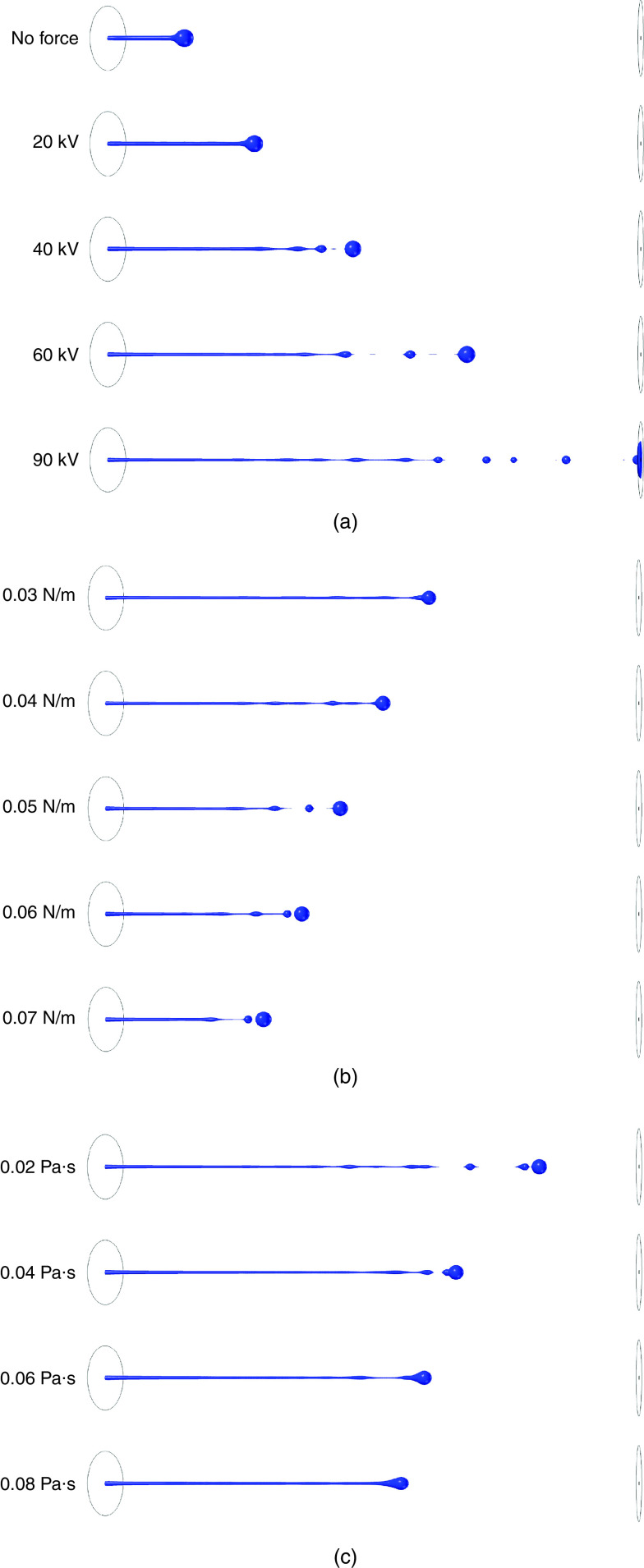
Researchers have exploited external actuators, such as electric123–125 and magnetic fields,126 to modulate droplet parameters such as droplet form, size, velocity, and acceleration. As an example, Du et al. numerically examined the influence of an electric field on charged droplets with different sizes.127 They showed how jets were accelerated by applying an electric potential between the boundaries. An increase in the applied electric field strengthened the induced forces on the jet and accelerated the jet instability. These results are shown in Fig. 11. The results showed that by applying 90 kV, many droplets were formed after 0.75 ms; however, no droplet was generated for electric fields less than 20 kV [Fig. 11 (a)]. The surface tension was another significant parameter in the jet characteristic. A higher surface tension led to a slower jet and a smaller breakoff length [(Fig. 11 (b)]. They also investigated the influence of viscosity on droplet ejection; they showed that viscosity and surface tension had similar influences on droplet ejection. Higher ink viscosities kept the droplet attached to the jet [(Fig. 11 (c)].
FIG. 11.
(a) Shape of liquid jet at t = 0.75 ms, μl = 0.02 Pa s, γ = 0.03 N/m at different electric potential values. (b) The shape of liquid jets at t = 0.55 ms and Vn = 90 kV at different surface tension values. (c) Shape of liquid jets at t = 0.65 ms and Vn = 90 kV at different liquid viscosity values. Reprinted with permission from Du et al., Int. J. Multiphase Flow 90, 46–56 (2017).127 Copyright 2017 Elsevier.
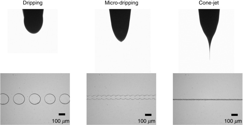
Jung et al. also used an electrohydrodynamic (EHD) jet printing process to print an ion-transistor on n-doped Si wafers that contained a 300-nm thick, thermally grown SiO2 layer.128 They demonstrated that various models of the droplet ejection and printing, including dripping, micro-dripping, and cone-jet models, can be obtained by modifying the applied voltage. Figure 12 shows these modes and the corresponding printed patterns.
FIG. 12.
Images of electrohydrodynamic (EHD) jetting modes, including dripping, micro-dripping and cone-jet, as well as the corresponding printed patterns. Flow-rate, working height, printing velocity and nozzle diameter were 0.01–0.04 μL/min, 100 μm, 20 mm/s, and 200 μm, respectively. The voltages applied for the dripping, micro-dripping, and cone-jet modes were 2.0 kV, 2.5 kV, and 2.8 kV, respectively. Reprinted with permission from Jung et al., Organic Electronics 52, 123–129 (2018).128 Copyright 2018 Elsevier.
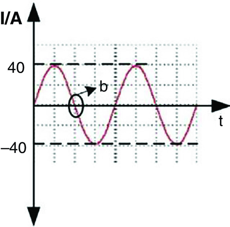
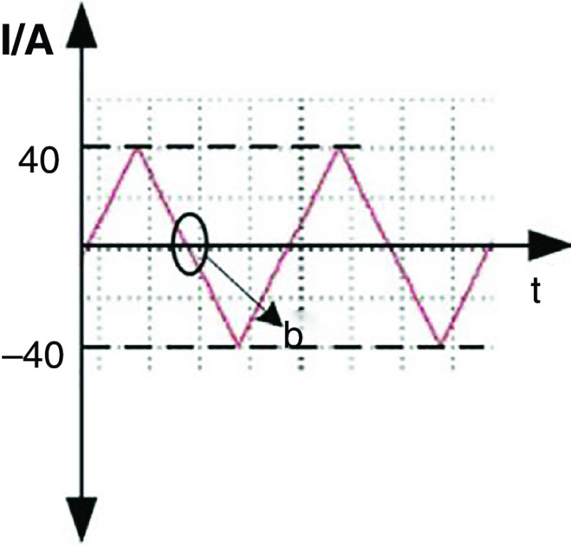
Wang et al. developed a new DOD printer by replacing the conventional actuators (i.e., piezoelectric and pneumatic actuators) with electromagnetic actuators.126 The inks used with this technology need to be metallic to be influenced by electromagnetic forces. For example, they used a nontoxic liquid metal known as gallium-indium eutectic alloy as an ink with this printing approach. The droplet generation and ejection processes were controlled by the power amplifier and signal source. It is more straightforward to control the electromagnetic pulse compared with its counterparts. Figure 13 shows snapshots of a single droplet generated by the application of a sine magnetic wave. During the first 0.01 ms, the liquid column gradually prolonged in the axial direction. At point b, the direction of the current changed, and the electromagnetic force acted as a restoring force instead of being driven. In the period of 0.01 to 0.02 ms, the energy of the stretching liquid was not adequate to overcome liquid surface tension; no droplet was ejected. At this step, the column gradually elongates in the axial direction. At point C, the direction of the electromagnetic force changed for the second time; due to surface tension, the rest of the liquid column flowed back to the nozzle. After two cycles, droplet generation did not occur by triangular waveform; this phenomenon is shown in Fig. 14 in greater detail.
FIG. 13.
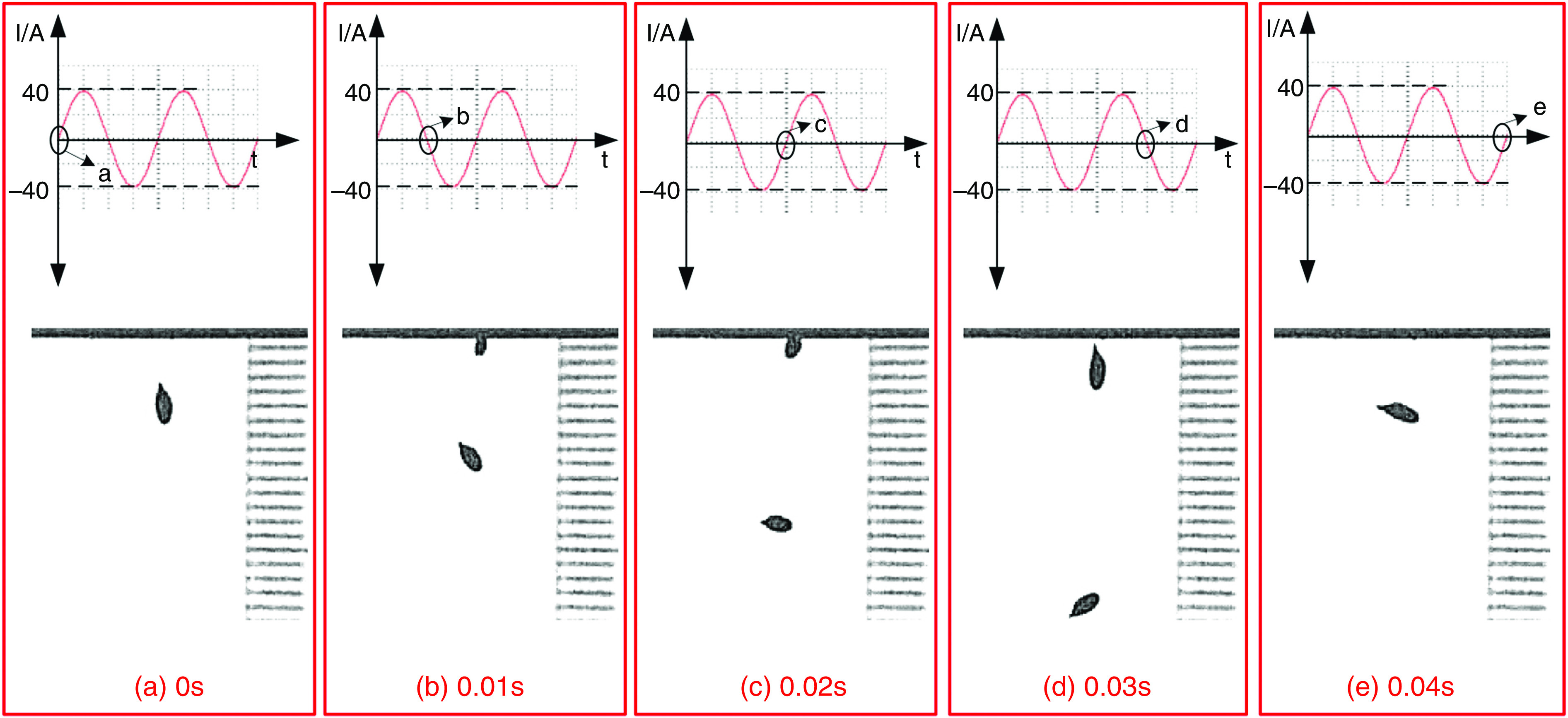
Droplet generation from a nozzle with 0.448 mm diameter with sine waveform and frequency of 50 Hz. Reprinted with permission from Wang et al., Vacuum 156, 128–134 (2018).126 Copyright 2018 Elsevier.
FIG. 14.
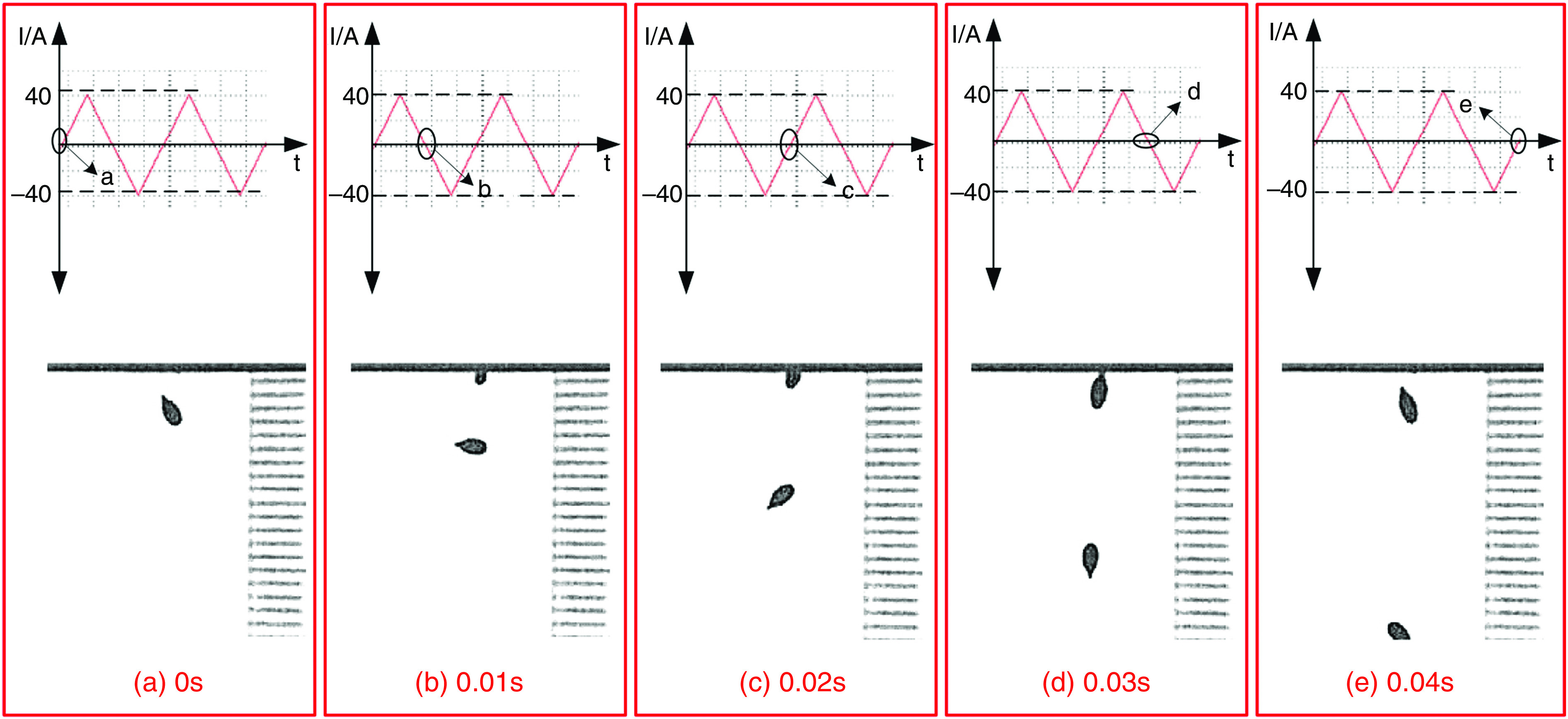
Droplet generation from a nozzle with 0.448 mm diameter with triangular waveform and frequency of 50 Hz. Reprinted with permission from Wang et al., Vacuum 156, 128–134 (2018).126 Copyright 2018 Elsevier.
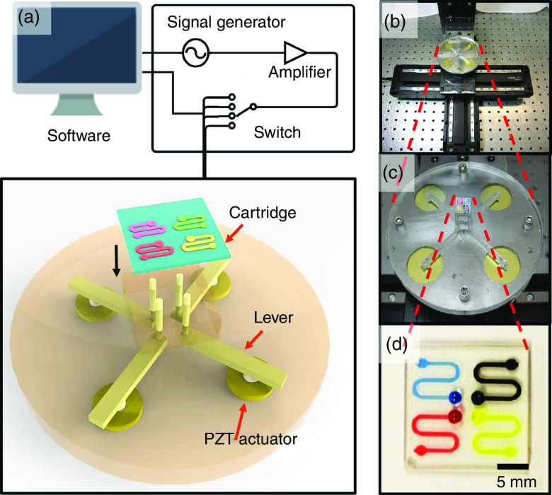
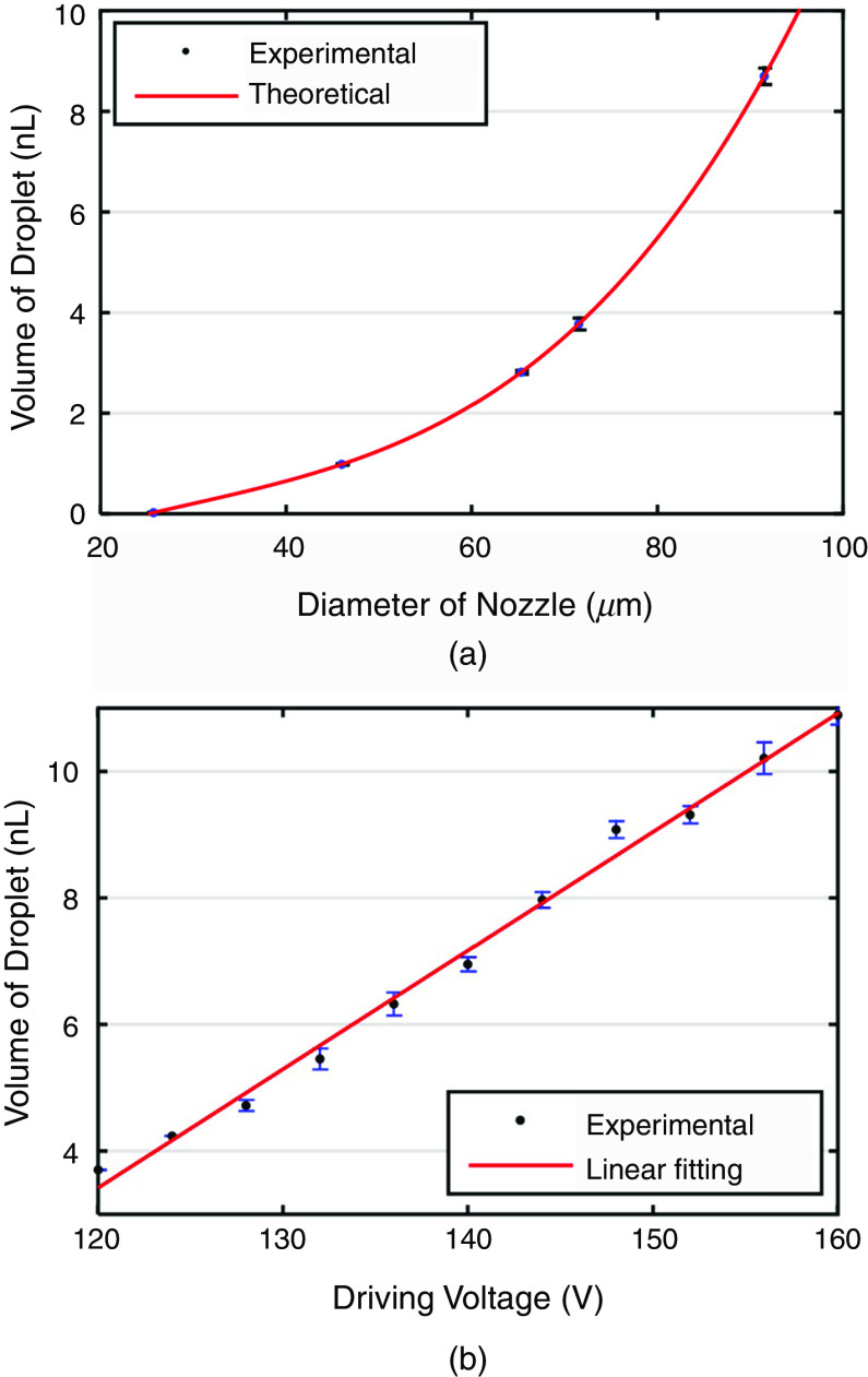
As can be seen in Fig. 15, the pulse waveform produced one droplet per cycle, which is similar to the two other waveforms. Li et al. proposed using an interchangeable microfluidic cartridge in a piezoelectric inkjet printer, which provided better control over the droplet size, dilution ration, and reagent combination.129 Figure 16 shows the microfluidic inkjet printing system and microfluidic cartridge component; a schematic of the mechanism associated with this system is also shown. Using this method, they reduced the volume of the ejected droplets from 23 picoliters to 10 nanoliters. The smaller droplets evaporated faster since they had a lower surface-area-to-volume ratio. Figure 17 shows the effect of the nozzle diameter and the driving voltage on the droplet volume. The droplets were smaller for the printing activities that involved a lower nozzle diameter and a weaker driving voltage. The other benefits of using a microfluidic cartridge include avoiding potential cross-contamination since the ink does not touch the printing actuator.
FIG. 15.
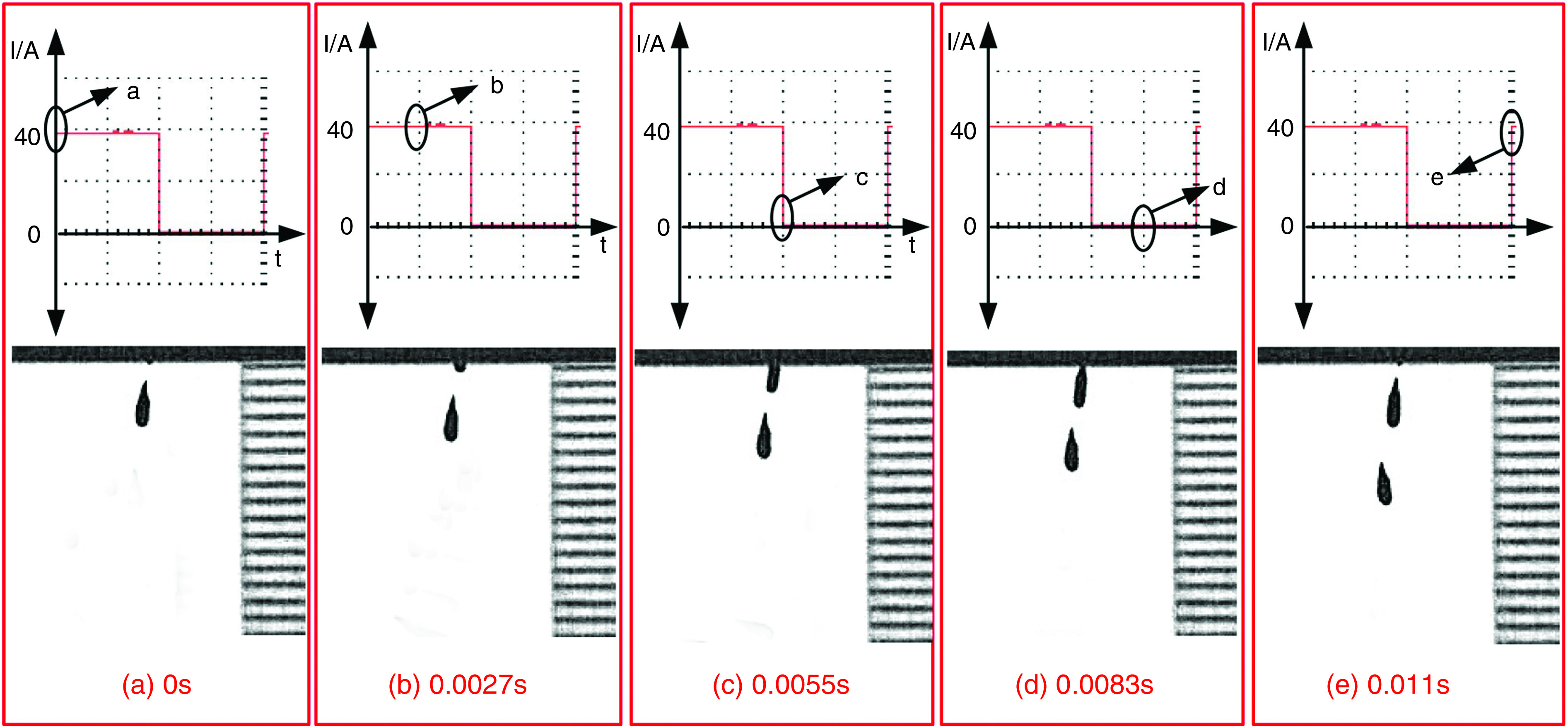
Droplet generation from a nozzle with 0.448-mm diameter with pulse waveform and frequency of 90 Hz. Reprinted with permission from Wang et al., Vacuum 156, 128–134 (2018).126 Copyright 2018 Elsevier.
FIG. 16.
(a) Schematic of microfluidic impact printing system. (b) Image of microfluidic impact printing system. (c) View of printer head with microfluidic cartridge. (d) Cartridge with four different color dyes. Reproduced from Biomicrofluidics 9(5), 054101 (2015),129 with the permission of AIP Publishing.
FIG. 17.
The relationship between droplet volume with both (a) nozzle diameter and (b) driving voltage. A: dwell time is 1 ms, and driving voltage is 120 V, and B: dwell time is 1 ms. Reproduced from Biomicrofluidics 9(5), 054101 (2015),129 with the permission of AIP Publishing.
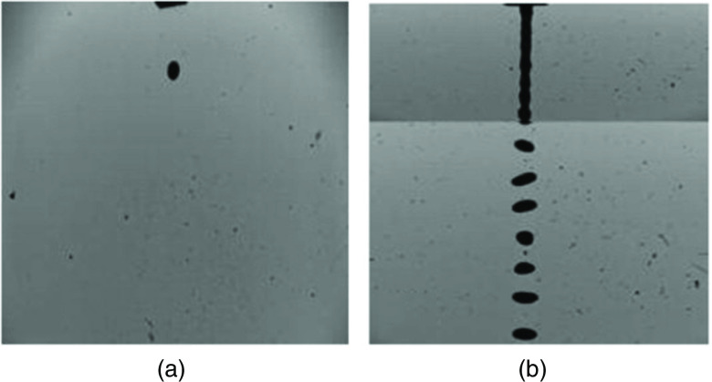
Minov et al. generated uniform and single droplets by exerting simultaneous control on the applied hydrostatic pressure and the piezoelectric actuator.130 One of the undesirable factors associated with ejecting non-uniform droplets is the presence of the air bubbles in the droplets. However, the droplets can “drip out” by controlling the fluid pressure until a meniscus is visible on the nozzle tip. Changing the liquid column height in the fluid tank is a solution to reach this aim. To generate uniform droplets in a continuous inkjet printer, a piezoelectric droplet generator with an appropriate resonance frequency was used. In this technique, a pressure supplier was used to create approximate 2 kPa pressure in the liquid to generate a continuous jet.130 Figure 18 shows uniform-sized droplets from a continuous inkjet printer.
FIG. 18.
Single- and uniform-sized continuous droplets. Reprinted with permission from Minov et al., Crop Protection 69, 18–27 (2015).130 Copyright 2015 Elsevier.
More recently, Li et al. investigated the influences of the excitation parameters on the spreading characteristics of the ejected droplets.131 They aimed to improve the ejection accuracy of the piezoelectric microjets. They proposed optimization of the shape of the electric pulse to (a) control the spreading processes of the droplets from initial forming to complete spreading as well as (b) prevent droplet interaction and merging. Their results showed that the applied voltage should be reduced when the spreading response speed of the droplets reaches the necessary amount to prevent merging of the ejected droplets. By increasing the amplitude and duty ratio of the pulse voltage, the printing spacing should be increased in order to avoid interactions between the spreading process and the neighbor droplets. They also reported the effect of the duty ratio (i.e., the time it takes for a signal to finish an on-and-off cycle) and pulse voltage on the droplet height and diameter. The droplet height and diameter were enhanced by increasing the voltage amplitude; the rate of this enhancement was reduced by increasing the voltage above 100 V. Furthermore, the droplet diameter and the height increased by the duty ratio. However, the rate of increase in these two parameters decreased for a duty ratio higher than 0.5.
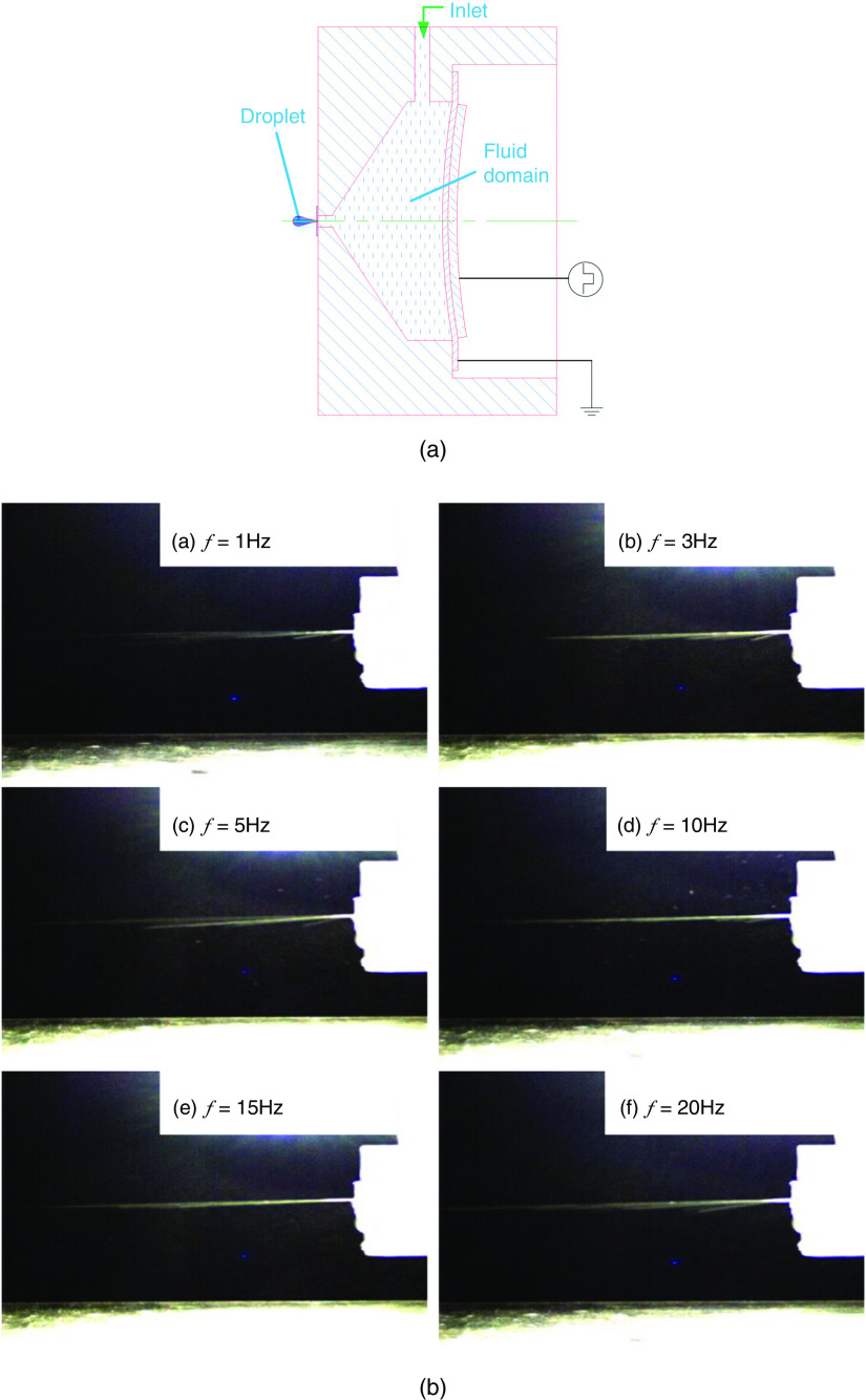
Li et al. designed a new piezoelectric micro-jet and analyzed the influence of frequency and materials of the shell on the inkjet printing performance.132 Figure 19 illustrates the structure of the piezoelectric microjet. The main components of this design include the piezoelectric component, the shell, and the nozzle. They applied a square wave with the voltage amplitude of 200 V and investigated influences of frequency on the inkjet printing process. The working fluid used in this study was water. Their results showed that an increase in the acoustic impedance intensified the nozzle pressure. However, the increase in the acoustic impedance had a negligible effect on the working frequency of the micro-jet. They also examined the impact of the working frequency on droplet generation; they showed that the injection frequency and the droplet velocity were intensified by frequency. However, the droplets no longer separated and gradually became continuous for frequency values above 200 Hz.
FIG. 19.
Schematic picture of the piezoelectric micro-jet and the injection status (at time t = 1 T) of the micro-jet when operating at different frequencies. Reprinted with permission from Li et al., Ceramics Int. 43, S27-S35 (2017).132 Copyright 2017 Elsevier.
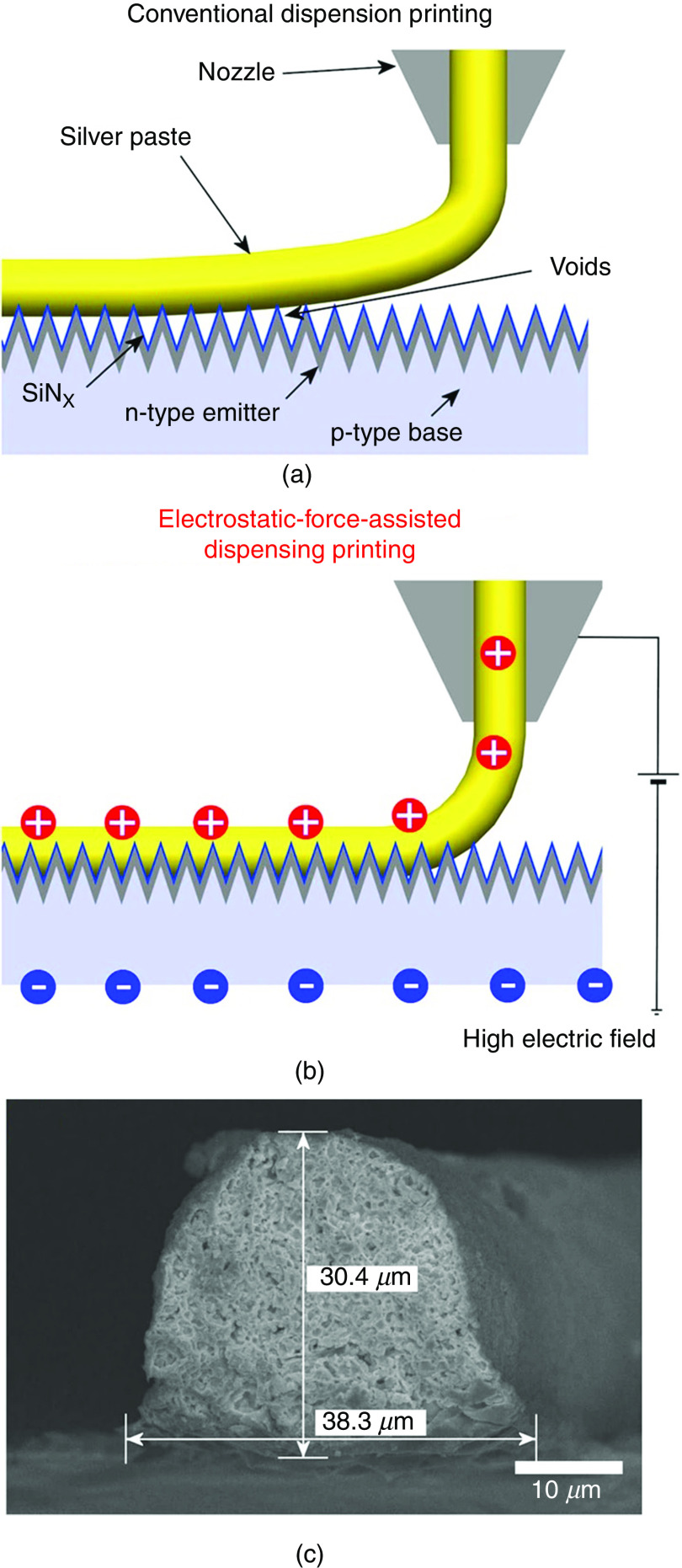
Shin et al. developed a novel technique to fabricate fine high-aspect-ratio electrodes. Figure 20 shows the schematic illustration of the technique and compares it with the conventional dispensing method. They developed a printing technique that applied the high electric field between the nozzle and the substrate; the electrostatic force on the accumulated charge of the meniscus pulled on the meniscus of the ink (silver paste) to form a conical shape (Taylor cone). The cone-shaped printed structures had lower contact resistivity on a textured surface compared with those made by conventional dispensing techniques. Using this technique, they reduced the contact resistivity of the electrodes from to (compared with those made by conventional dispensing printing). The printed structures showed better adhesion and did not easily peel off from the textured surface.133
FIG. 20.
Schematic illustration of the interfacial contact of the ink (silver paste) on the textured surface of a crystalline silicon solar cell printed by (a) a dispensing printing technique, (b) an electrostatic-force-assisted dispensing printing technique, and (c) a cross-sectional SEM image of its electrode. Reprinted with permission from Shin et al., Sci. Rep. 5, 16704 (2015).133 Creative Commons Attribution 4.0 International License.
A. Positioning and interaction of droplets on substrates
Positioning and the interaction of the ejected droplets on the substrate is the second step in the printing process. The inertia, viscous, capillary, and gravitational forces affect the spreading of the droplets on the substrates. The non-dimensional numbers associated with this phenomenon are the Reynolds, Weber, Ohnesorge, and Bond numbers. The gravitational force has a negligible effect compared with the surface tension forces. The typical droplet properties are and . These values result in a Bond number considerably lower than 1 ( . This number is the ratio of the gravitational force to the surface tension force. In turn, a Bond number considerably smaller than 1 means that the gravitational force will be negligible compared to the surface tension force. Therefore, the inertia, viscous, and capillary forces will govern droplet-substrate interaction. When the droplet impacts the substrate, it will spread, rebound, or splash. On the wetting surface, the droplet will spread more, and the diameter of the droplet will become larger. On the other hand, the droplet may recede or rebound up on a non-wetting surface. The droplet may splash on the rough substrate, which will lead to the wavy boundaries. Both surface and ink properties should be modified to enhance the droplet/substrate interaction as well as the uniformity and quality of the printed patterns. Stringer and Derby showed that the width of the linear deposit has a minimum that depends on the droplet size and the surface energy interaction of the substrate and the droplet.134
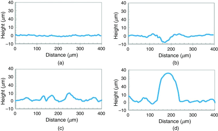
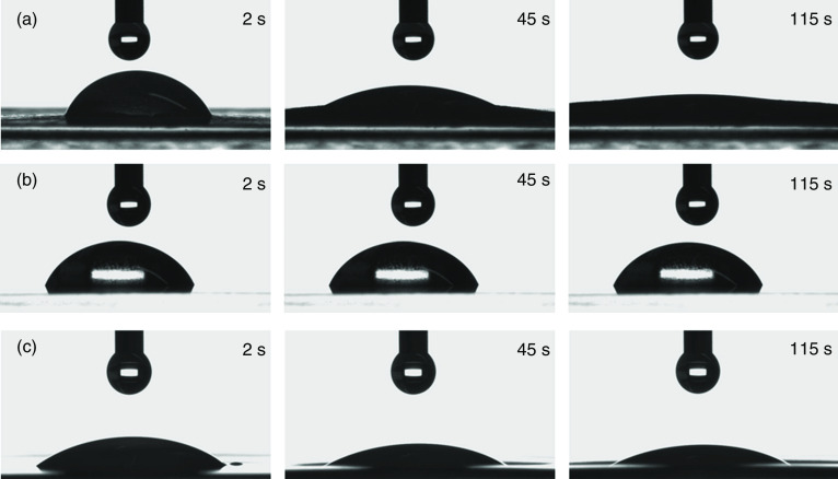
Several studies have been conducted to modify the interaction between droplets and substrates in order to enhance printing quality and uniformity. For example, Planchette et al. studied the effect of substrate wettability on the shape of droplet.135 They examined interactions of aqueous droplets with three types of substrates, including the hydrophilic fast dissolving substrate named Rapidfilm®, the hydrophobic non-porous film from CURE Pharmaceutical®, and the hydrophilic non-porous film from CURE Pharmaceutical®. Figure 21 shows profilometry of the Rapidfilm® and the hydrophobic non-porous film from CURE Pharmaceutical® before and after printing. The non-printed Rapidfilm® was smooth; the maximum rugosity was 2 . In the printed Rapidfilm®, the depth of crater was 8.5 which was surrounded by a crown with 3 height and 220 diameter. The non-printed hydrophobic non-porous film from CURE Pharmaceutical® was more rugged; the surface elevation was approximately 10 . The printed hydrophobic non-porous film from CURE Pharmaceutical® had hemi-spherical shaped protuberances with 35 height and 130 diameter. They also analyzed the interactions of aqueous droplets with these substrates after coating them with PEG6000; coating the substrates increased the wettability of the substrates. The aqueous droplets had more protuberances on the uncoated hydrophobic non-porous substrate than the PEG 6000-coated one. Figure 22 shows the shape of a droplet on both coated and uncoated substrates. On the hydrophobic and porous substrates, a consistent surface texture with topological deviations of less than 12 was observed in the printed films. On the hydrophobic and non-porous substrates, the shape of the droplets changed to a hemi-spherical cap with 35 height after drying. Since the hydrophobic surface minimizes absorption and spreading, pre-coating the substrate with a PEG-based hydrophilic material was used to provide a more homogeneous distribution of printed APIs.
FIG. 21.
Profilometry of (a) of Rapidfilm® Tesa Labtec without printing, (b) Rapidfilm® with printed spots of 10 droplets of sodium picosulfate ink, (c) hydrophobic non-porous film of CURE Pharmaceutical® without printing, and (d) hydrophobic non-porous film with printed spots of 10 droplets containing sodium picosulfate ink. Reprinted with permission from Planchette et al., Int. J. Pharm. 509(1–2), 518–527 (2016).135 Copyright 2016 Elsevier.
FIG. 22.
Contact angle of a water droplet on uncoated and coated hydrophobic non-porous CURE Pharmaceutical® substrate ( ). Scale bars indicate 500 μm. Reprinted with permission from Planchette et al., Int. J. Pharm. 509(1–2), 518–527 (2016).135 Copyright 2016 Elsevier.
The droplet must impact the substrate in a manner that prevents splashing and leaves a single isolated spread drop on the substrate. Stow et al. experimentally showed that the following condition must be satisfied to prevent splashing:136
| (4) |
In the above equation, is only a function of surface roughness. It will be around 50 for surfaces that are flat and smooth.
Pegg et al. conducted analytical and numerical studies to analyze elastic deformation of the substrate and highlighted the effect of a flexible substrate on the contact line velocity and jet behavior.137 Their results showed that oscillation of the substrate caused a blow-up of splash jet and splashing. Deflection of the elastic substrate strongly affected the radius of the contact line. If the acceleration of the contact line was negative, then the jet flow was smooth and finite. The oscillation of the substrate in the early impact stage may change the sign of the contact line. This phenomenon was shown in an elastic substrate that had a small period of natural vibration. However, positive acceleration of the contact line resulted in a blow-up of the jet flow along with secondary torus jet formation.137
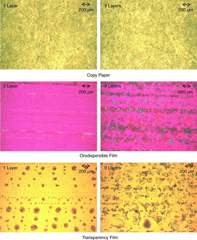
It should be noted that the surface properties of the substrate affect the shape of the printed droplets. As an example, Fig. 23 shows the shapes of the droplet on three different types of paper. These results showed that the substrate with similar properties to copy paper was the most favorable one for the preparation of a drug-delivery system by thermal inkjet printing. However, the droplet diameter was greater than the nozzle diameter. Figure 24 shows the substrates after one and nine layers of the API printing. The copy paper showed no crystals because the ink was absorbed by the substrate matrix during the printing process. In orodispersible films, the API crystals were arranged in a line formation. The crystals were observed after two cycles of printing and grew when additional layers were printed. The crystals were also observed on transparency film; these features were detected after one layer of printing. It is also noted that the copy paper contained the greatest amount of API after nine layers of API printing; the transparency film and the orodispersible material showed the next highest amounts of API.138
FIG. 23.
Effect of various substrates on droplet shape in time: (a) copy paper, (b) transparency film, and (c) orodispersible film. Reprinted with permission from Genina et al., Eur. J. Pharm. Biopharm. 85(3), 1075–1083 (2013).138 Copyright 2013 Elsevier.
FIG. 24.
Polarized light microscope micrographs of the drug-ink on the three different substrates. Reprinted with permission from Genina et al., Eur. J. Pharm. Biopharm. 85(3), 1075–1083 (2013).138 Copyright 2018 Elsevier.
Endowing the substrate with improved chemical/physical properties is an efficient approach to decrease the wetting of printed droplets and increase the printing resolution.139–142 Rebounding and splashing of the droplets is associated with drier substrates; on the other hand, the droplets tend to spread more on wetter surfaces, resulting in the formation of a flat disc-shaped dot.135,143 The surface roughness of the substrate may also cause the droplets to splash, reducing the resolution of the pattern.144,145
B. Drying and other solidification mechanisms to produce a solid deposit
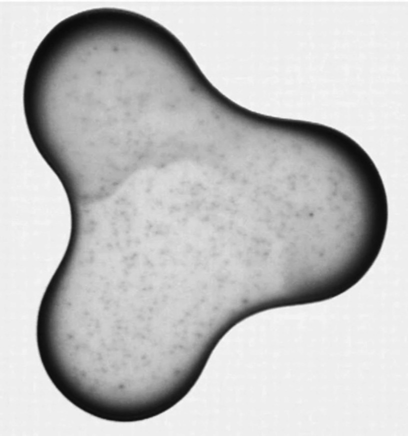
The patterns need to be both dried and solidified in order to complete the inkjet printing process. This step has a significant influence on the uniformity and quality of the printed pattern. Inhomogeneous evaporation of the solvent in the printed pattern is one of the main causes of non-uniformity in the printed pattern. This effect, which is known as the coffee ring effect, is caused due to accumulation of solute material at the rim of the drying droplet. Figure 25 shows an example of this effect. Convective flow in the droplet can also result in the coffee ring effect. When a coffee droplet dries on a surface, the density of color is greater at the perimeter of the droplet.146,147 An evaporation droplet contact line is pinned on a substrate that results in capillary flow toward the edges. Suspended material is carried to the edges of the droplet by capillary flow. This phenomenon, called the “coffee ring effect,” reduces the printing accuracy. Several mechanisms, which involve controlled evaporation of the solvent, have been reported to minimize this effect.148–154 Soltman et al. showed the effect of different drop spacings and temperatures on printed line morphologies. They showed that the coffee ring effect can be controlled by the evaporation profile of the drying drops and lines.155
FIG. 25.
Coffee ring effect after drying. Reprinted with permission from Deegan et al., Nature 389(6653), 827 (1997).147 Copyright 1997 Springer Nature.
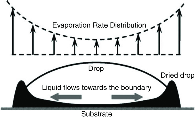
Marangoni flow is another phenomenon that may occur during the drying step; this phenomenon may also reduce the uniformity of the printed droplet. Marangoni flow occurs when there is a surface tension gradient in the fluid that pulls the flow away from a region of low surface tension. Depending on the droplet type, this phenomenon can carry the fluid either toward the edge of the droplet or toward the center of the droplet. Figure 26 shows a microscope image of the Marangoni flow; it is clear from this image that this phenomenon can carry the fluid to the edge. Since evaporation of the droplet is fastest at the contact edge (Fig. 27), a convective flow called outward convective flow occurs in the droplet to make up for the lost fluid. Outward convective flow in the droplet is induced because of fast evaporation at the contact edge; the formation of an uneven ring and a structure with random crystallinity is associated with this phenomenon. Figure 26 shows the effect of different solvent compositions in a TIPS-PEN [6,13 bris (triisopropylsilylethynyl) pentacene] droplet.156 Incorporation of a minor component with a higher boiling point and lower surface tension than the major solvent can diminish this undesirable effect.156 Lim et al. produced a crystal that induced a Marangoni flow in the direction opposite to the convective flow to control the evaporation process and develop a more accurate printed structure.156 Tekin et al. also controlled the coffee ring effect by mixing a solvent in the ink to produce a homogenous polymer film.151
FIG. 26.
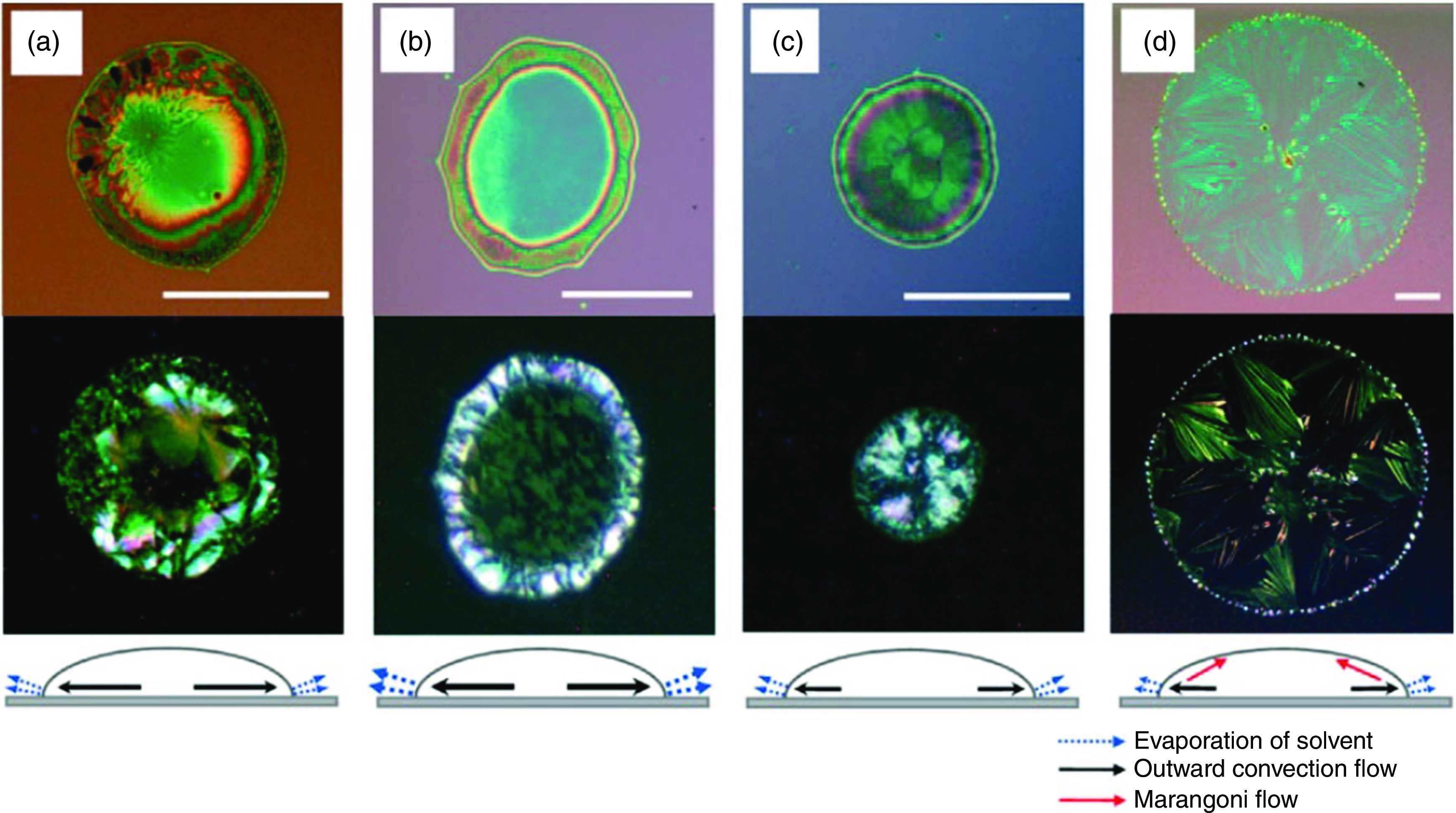
Optical microscope and polarized images of inkjet-printed 6,13-bis(triisopropyl-silylethynyl) pentacene (TIPS-PEN) droplets with various solvent compositions: (a) chlorobenzene and mixed-solvents containing chlorobenzene and 25 vol. %, (b) hexane, (c) o-dichlorobenzene, and (d) dodecane. Reprinted with permission from Adv. Funct. Mater. 18(2), 229–234 (2008).156 Copyright 2008 John Wiley and Sons.
FIG. 27.
Schematic of liquid [poly(3,4-ethylenedioxythiophene):poly(styrenesulfonate)] flow and the rate of evaporation in the droplet. Reprinted with permission from Zhou et al., Int. J. Adv. Manuf. Technol. 48(1–4), 243–250 (2010).153 Copyright 2009 Springer Nature.
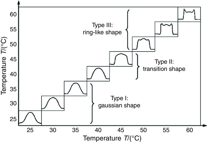
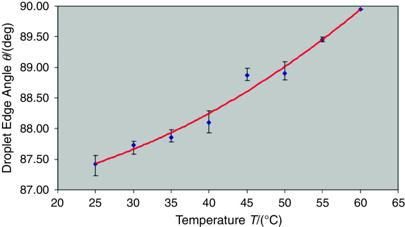
The drying process in the printed droplets must be controlled to obtain uniform thin films. Zhou et al. showed that the substrate temperature is an important parameter in the drying behavior due to the high surface-area-to-volume ratio for the droplets. They characterized printed droplets containing poly(3,4-ethylenedioxythiophene): poly(styrenesulfonate) on substrates with different temperatures. Figures 28 and 29 show the effect of the substrate temperature on the droplet shape and the edge angle of the droplet, respectively. They concluded that the temperature of the substrates significantly affected the shape of the dried droplets; the droplet shape can be placed in three categories, including the Gaussian shape (<40 °C), the transition shape (between 40 °C and 50 °C), and the ring-like shape (>50 °C). The printed patterns associated with the Gaussian shape region were taller than the printed patterns associated with the other regions. The ring-like shape was associated with the lowest height and splashing effects.153
FIG. 28.
Shapes of droplets on the same substrates with different temperatures. Reprinted with permission from Zhou et al., Int. J. Adv. Manuf. Technol. 48(1–4), 243–250 (2010).153 Copyright 2009 Springer Nature.
FIG. 29.
Effect of substrate temperature on droplet width and edge angle. Reprinted with permission from Zhou et al., Int. J. Adv. Manuf. Technol. 48(1–4), 243–250 (2010).153 Copyright 2009 Springer Nature.
VI. ENGINEERING CONSIDERATIONS
There are many design parameters, including printer design and ink characteristics, which can affect the printing process and printing quality. The possible range of the processing parameters may be limited because of printer manufacturing restrictions or biological considerations. The ink properties such as surface tension and viscosity are the most important factors affecting the printing quality. The printed patterns will also be influenced by the nozzle design parameters, including inner diameter and constitutive material, as well as the mechanisms of droplet generation and ejection. All of these parameters should be optimized to process uniform and high-resolution patterns as well as meet the biological and engineering restrictions. The cell viability characteristics in the ink prior to printing, during printing, and after printing are another design parameter that restricts printing of viable cells.157,158
A. Ink properties
As mentioned previously, the viscosity and the surface tension of the ink significantly influence the quality, resolution, and uniformity of the ink printed patterns. For example, the viscosity affects the Reynolds, Weber, and Ohnesorge numbers. The surface tension also influences the Weber, Ohnesorge, and Bond numbers. These non-dimensional numbers significantly regulate the printing outcome. The surface tension and viscosity of typical inks in recent 3D printers is presented in Table II. These two parameters affect all of the three steps of the printing process, including fluid ejection, droplet generation, positioning of droplets on substrates, interaction of droplets on substrates, drying mechanisms, and solidification mechanisms. These parameters also influence the printability of various fluids and inks.
TABLE II.
Inks used in inkjet printing.
| Ref | Ink | Ink viscosity (mPa.s) | Ink surface tension ( ) |
|---|---|---|---|
| 108 | Ethylene Glycol | 20 | 50 |
| 179 | Water | ||
| 185 | 50 Ethylene Glycol-50 Water | 5.05 | 46.7 |
| 126 | 75 gallium-25 indium | 1.7 | 624 |
| 126 | 75 gallium-25 indium | 1.7 | 624 |
| 75 gallium-25 indium | 1.7 | 624 | |
| 113 | fibroblasts and sodium alginate | 45.2 | |
| 130 | Water | ||
| 181 | Dowanol | ||
| 188 | Nano silver | 15.7 | 73.5 |
| 106 | Glycerol(G)-Water(W) | 1–22.5 | 66.4–7.6 |
| 106 | Glycerol(G)-Water(W) | 1–22.5 | 66.4–7.6 |
| 106 | Glycerol(G)-Water(W) | 1–22.5 | 66.4–7.6 |
| 172 | Water | ||
| 189 | - Water | 4.45 | 88 |
| 183 | Dowanol | 10.17 | 15.55 |
| 183 | Dowanol | 10.17 | 15.55 |
| 183 | Dowanol | 10.17 | 15.55 |
| 184 | Ethyl acetate | 0.452 | 2.367 |
| 184 | Ethyl acetate | 0.452 | 2.367 |
| 184 | Ethyl acetate | 0.452 | 2.367 |
| 190 | Water-like | 0.002 | 35.71 |
| 191 | Commercial AgNp | 6.8 ± 0.7 | 30 ± 1 |
| 192 | 5 Fe3O4-95 (nanoparticles+ UV Curable matrix resin) | 18.03 | 23.91 |
| 192 | 10 Fe3O4-90 (nanoparticles+ UV Curable matrix resin) | 18.08 | 20.91 |
| 193 | 6 Hydroxypropyl cellulose- 94 Water | 45 | 44.5 |
The viscosity of typical inks is 0.4–25 mPa.s (Table I). It can be extended to 100 mPa.s for the thermally actuated system.159 It has been shown that printing in more viscous inks is associated with higher resolution in inkjet printing. However, nozzle clogging is more likely when more viscous inks are used. Lowering the ink viscosity is a mechanism to prevent nozzle clogging. However, a low ink viscosity is associated with increased spreading of the ink on the substrate and reduced resolution of the printed pattern.160 It should also be mentioned that more viscous fluids tended to obstruct the nozzle, and consequently require higher pressure pulses for ink ejection.161 Nozzle-free approaches have been introduced as an alternative method for printing high viscosity inks (e.g., viscosity in the range of 1–300 mPa.s).162–164 However, precoating of the substrate, which is often utilized in this approach, is a time-consuming process.
Mixing materials or cross-linkers with different concentrations is one of the solutions for controlling viscosity.165 Heating of the ink is another solution that is commonly used in thermal inkjet printers. However, this approach may damage living cells or biological materials in the ink.165,166 Printing of inks containing cells has got more attention recently.167–169 It has been demonstrated that viscosity increases with cell concentration at a given shear rate. However, the surface tension of the fluid decreases along with an increase in the living cell concentration.113,114 Surface tension also has an important effect on drop formation at the nozzles. In piezoelectric inkjet printers, a drop is ejected when the electric pulse exceeds a threshold value. A higher surface tension is associated with a larger threshold value. If the electric field is not strong enough, then the drop remains stable or oscillates at the nozzle tip. In addition to viscosity, the surface tension is an important parameter in drop formation. Surface tension also plays an important role in ligament behavior; this behavior can be described in two directions. In the generating line direction, it leads to a neck radius increase; in the peripheral direction, surface tension decreases the neck radius (Fig. 30)161,170,171
FIG. 30.
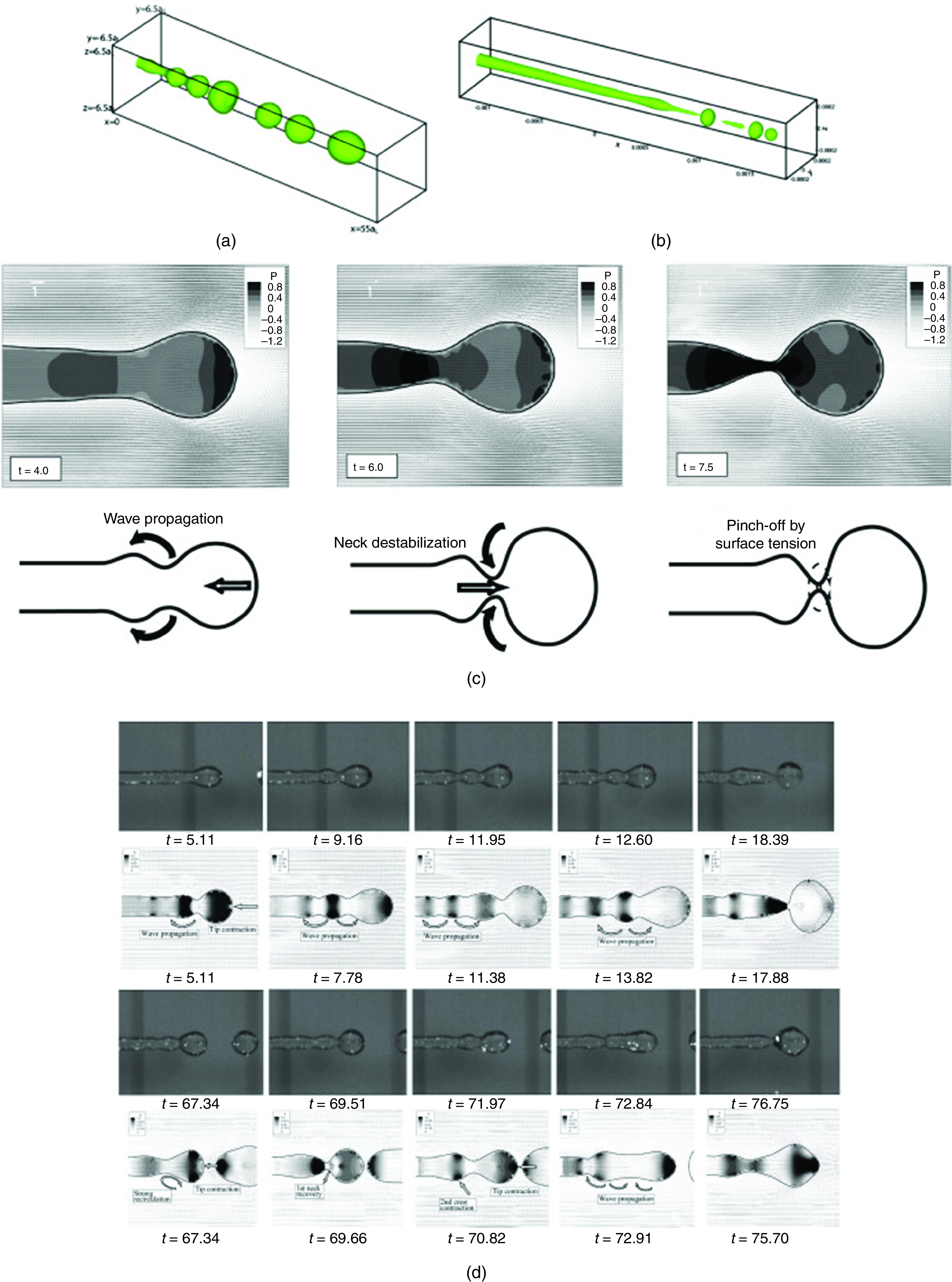
Effect of surface tension ligament. Reprinted with permission from Shinjo et al., Int. J. Multiphase Flow 36(7), 513–532 (2010).170 Copyright 2010 Elsevier.
B. Nozzle properties
The nozzle is one of the most important elements of the inkjet printer since it has important effects on the functionality and precision of the 3D printing process. Direct interactions of the nozzle with the ink and the droplet significantly affect the quality, uniformity, and resolution of the printed structures. The inner diameter of the nozzle of the inkjet printer highly affects the Reynolds, Weber, Ohnesorge, and Bond numbers. Therefore, this parameter must have an important influence on the three steps of printing, including (a) ejecting fluids and generating droplets, (b) droplet/substrate interaction, and (c) drying and solidification. Table III summarizes the inner diameter of recently developed 3D printers; this parameter ranges from . Table IV shows the voltage rising/falling/dwelling time, voltage, frequency, and waveform from several studies. The nozzles are also constructed from glass. The surface properties of the nozzle greatly influence the printing efficiency. Table III considers both the inner diameter of the nozzle and the diameter of the generated droplets. It is clear that these two diameters are not identical. The difference can be explained by considering the nozzle-substrate distance, mechanical vibration of the printer, substrate properties, and drop solidification process.157,162
TABLE III.
Engineering design of inkjet printers.
| Ref | Nozzle material | Nozzle (inner diameter) | Droplet diameter | Actuation | Droplet velocity | Breakoff length |
|---|---|---|---|---|---|---|
| 108 | Glass | 60 ( ) | Less than 80 | PZTa | 680 ( ) | |
| 179 | Glass | 354 ( ) | 869 ( ) | PZTa | 1323 ( ) | |
| 185 | Glass | 50 ( ) | PZTa | 39 ( ) | ||
| 126 | 448 ( ) | PEFb | <1437 ( ) | |||
| 126 | 448 ( ) | PEFb | ||||
| 126 | 448 ( ) | PEFb | ||||
| 113 | Glass | 120 ( ) | 147 ( ) | PZTa | 935 ( ) | |
| 130 | Glass | 123.4 ± 5.2 ( ) | 390.2 ± 4.6 ( ) | PZTa | 0.49 ± 0.01 ( ) | |
| 181 | PZTa | 9 ( ) | 333 ( ) | |||
| 188 | 27 ( ) | 54.6–45.1 ( ) | PZTa | |||
| 106 | Glass | 30 ( ) | PZTa | ** | ||
| 106 | Glass | 30 ( ) | PZTa | *** | ||
| 106 | Glass | 30 ( ) | PZTa | **** | ||
| 172 | 50 ( ) | 10–30 ( ) | PZTa | |||
| 189 | Nozzle-free | Nozzle-free | TSTc | |||
| 183 | PZTa | 6.5 ( ) | 0 | |||
| 183 | 5.047 pL | PZTa | 5.51 ( ) | |||
| 183 | 5.03 pL | PZTa | 5.51 ( ) | |||
| 184 | Glass | 50 ( ) | 12, 13.4, 23.4 ( ) | PZTa | 0.84, 1.08, 2.61 ( ) | |
| 184 | Glass | 50 ( ) | 6.2, 7.99, 10.2 ( ) | PZTa | 0.67, 1, 1.2 ( ) | |
| 184 | Glass | 50 ( ) | 1.1, 2, 5.9 ( ) | PZTa | 1.83, 1.47, 2.55 ( ) | |
| 194 | Glass | 36 | PZTa | 8 (m/s) | ||
| 192 | 35 | 70–75 | PZTa | |||
| 195 | 30 | 26 | PZTa |
Piezoelectric.
Pulse electromagnetic force.
Thermo cavitation technique.
**In low viscosity fluid (0 G-100W and 20 G-80W), satellites are observed. By increasing the viscosity (40 G-60W and 60 G-40W), the droplet has no satellite and is solitary. In further increasing the viscosity (70 G-30W), no droplet is generated.
***Due to high surface tension, no droplet is generated in 70 G-30W ink.
****This waveform can eject the 70 G-30W ink.
TABLE IV.
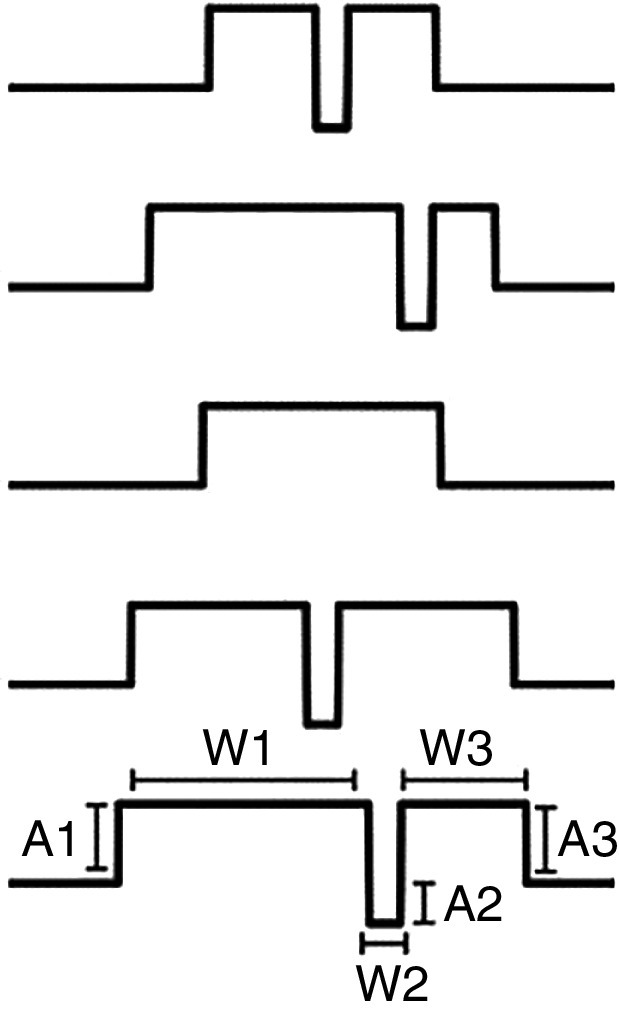
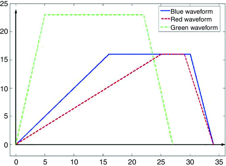
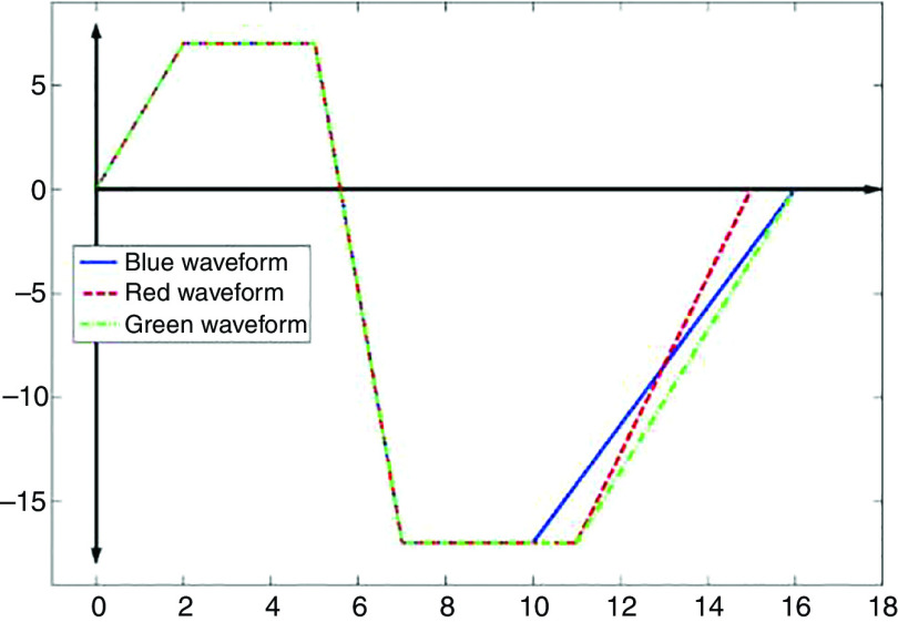
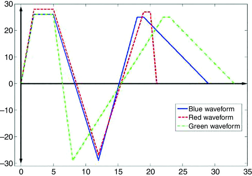
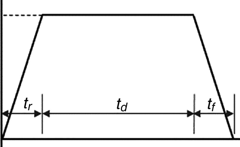
Waveform characteristics of piezoelectric inkjet printers.a
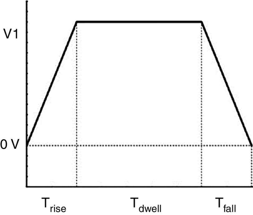
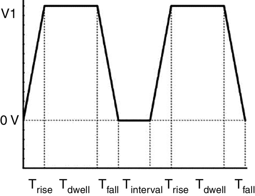
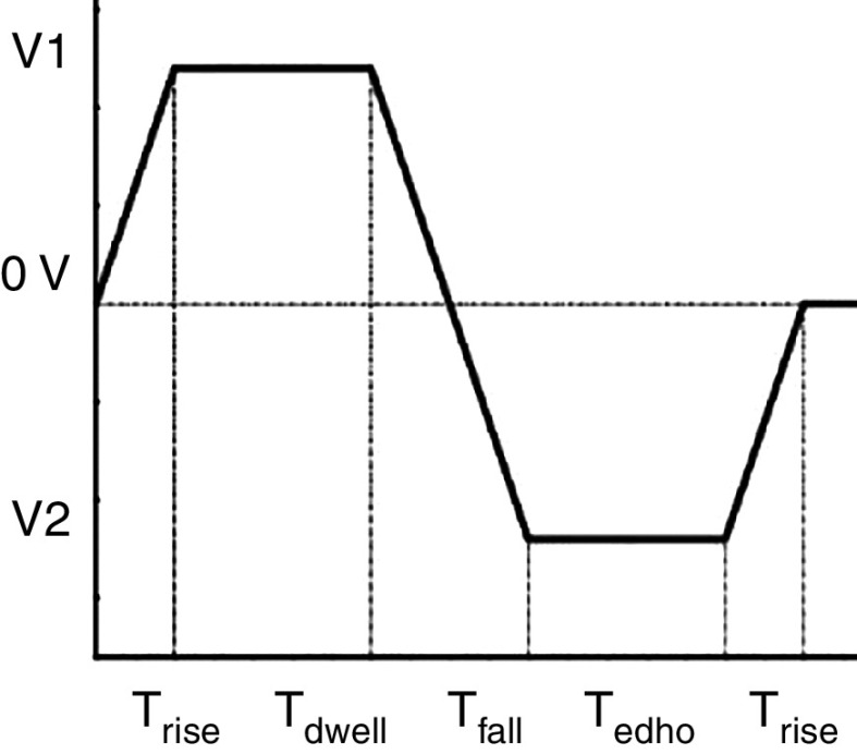
| Ref | Voltage rising/falling/dwelling time ( ) | Voltage (V) | Frequency (Hz) | Waveform | Waveform |
|---|---|---|---|---|---|
| 108 | 7/7/18 | 85 | 3000 | ||
| 179 | 220 | 102 | Triangular | ||
| 185 | (2/2/6) | 60 | 1000 | Unipolar Trapezoidal | |
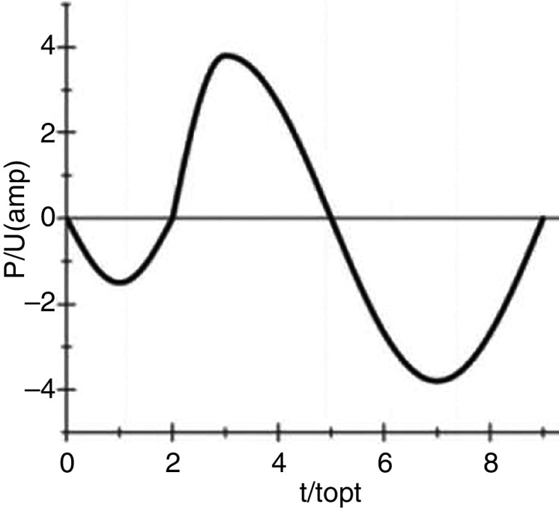
| 126 | b = 10 | is input current | 50 | Sine |
 b
b
|
| 126 | b = 10 | 50 | Triangular |
 c
c
|
|
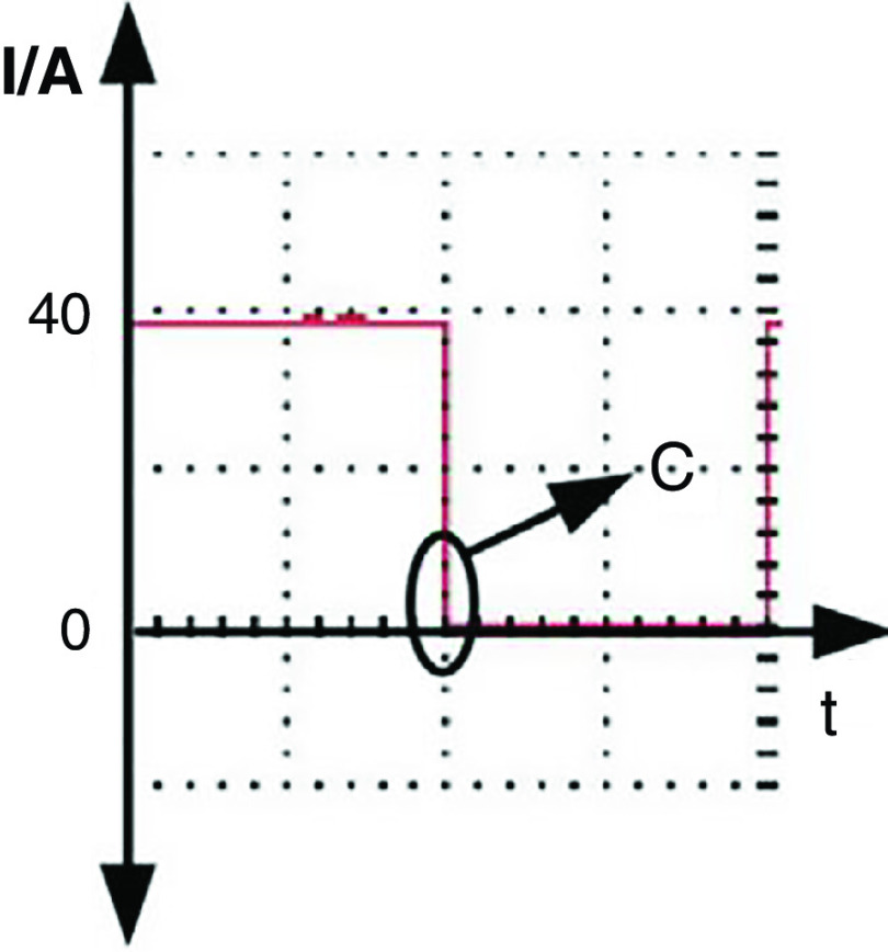
| 126 | c = 5.510 | 90 | Pulse wave |
 d
d
|
|
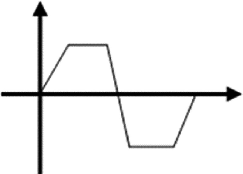
| 113 | 3/3/20 | 45 | 50 | trapezoidal |
 e
e
|
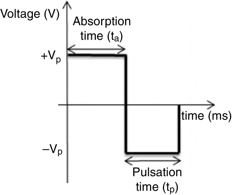
| 130 | & : Absorption time Pulsation time | 4.5 | 8000 |
 f
f
|
|
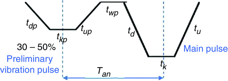
| 181 | 14 | Preliminary vibration (30%) |
 g
g
|
||
| 188 | 3.7–4.5 | Similar to sine |
 h
h
|
||
| 106 | 5/5/14 | 12 | 1000 | Single wave |
 i
i
|
| 106 | 5/5/14 | 20 | 1000 | Double waveform |
 j
j
|
| 106 | 5/5/14 =14, =5 | 20 | 1000 | Bipolar waveform |
 k
k
|
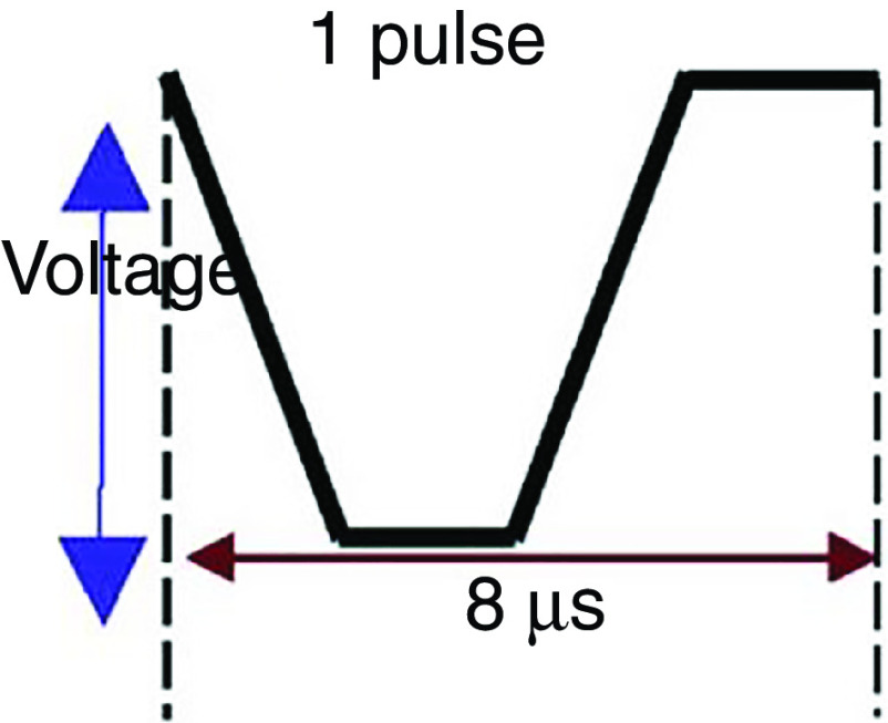
| 172 | Table S1 of the ESI | 50–150 | 10 |
 l
l
|
|
| 189 | Acoustic shock wave | ||||
| 183 | 14 | Basic |
 m
m
|
||
| 183 | mentioned in the waveform | 15 | U |
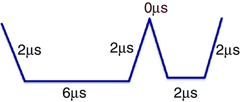 n
n
|
|
| 183 | mentioned in the waveform | 16 | W |
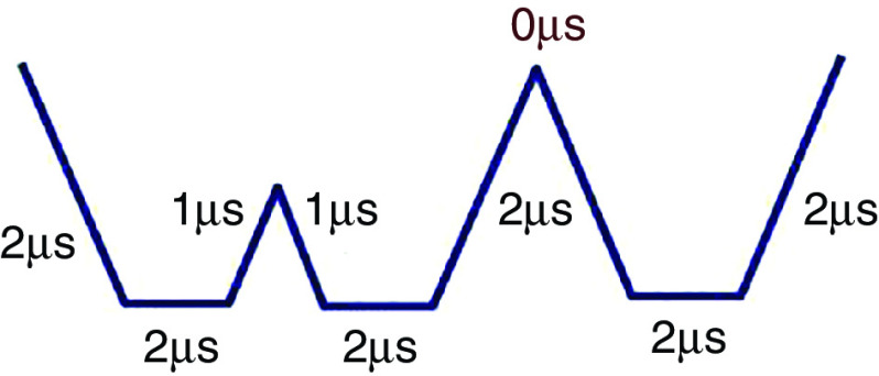 o
o
|
|
| 184 | mentioned in the waveform | 500 | Unipolar |
 p
p
|
|
| 184 | mentioned in the waveform | 500 | Bipolar |
 q
q
|
|
| 184 | 500 | Tripolar |
 r
r
|
||
| 195 | 3/3/16 | 20 | 10000 | Unipolar Trapezoidal |
 s
s
|
Each similar row numbers in the tables (II, III, and IV), from row 1 (Ref. 93) to row 21 (Ref. 165) shows the results of the same study.
Reprinted with permission from Wang et al., Vacuum 156, 128–134 (2018). Copyright 2018 Elsevier.
Reprinted with permission from Wang et al., Vacuum 156, 128–134 (2018). Copyright 2018 Elsevier.
Reprinted with permission from Wang et al., Vacuum 156, 128–134 (2018). Copyright 2018 Elsevier.
Reprinted with permission from Xu et al., Langmuir 30 (30), 9130–9138 (2014). Copyright 2014 American Chemical Society.
Reprinted with permission from Minov et al., Crop Protection 69, 18–27 (2015). Copyright 2015 Elsevier.
Reprinted with permission from Oktavianty et al., World Acad. Sci. Engineer. Technol. Int. J. Mech. Aero. Ind. Mechatron. Manuf. Engineer. 11 (4), 880–889 (2017).
Reprinted with permission from Zhang et al., MATEC Web of Conferences, 2015. Creative Commons Attribution 4.0 International License 4.0.
Reprinted with permission from Liu et al., Appl. Phys. A 111 (2), 509–516 (2013). Copyright 2013 Springer Nature.
Reprinted with permission from Liu et al., Appl. Phys. A 111 (2), 509–516 (2013). Copyright 2013 Springer Nature.
Reprinted with permission from Liu et al., Appl. Phys. A 111 (2), 509–516 (2013). Copyright 2013 Springer Nature.
Reprinted with permission from Bartholomew et al., RSC Adv. 6 (65), 60215–60222 (2016).
Reprinted with permission from Oktavianty et al., Add. Manuf. 25, 522–531 (2019). Copyright 2019 Elsevier.
Reprinted with permission from Oktavianty et al., Add. Manuf. 25, 522–531 (2019). Copyright 2019 Elsevier.
Reprinted with permission from Oktavianty et al., Add. Manuf. 25, 522–531 (2019). Copyright 2019 Elsevier.
Reprinted with permission from Snyder et al., Precis. Engineer. (2018). Copyright Elsevier.
Reprinted with permission from Snyder et al., Precis. Engineer. (2018). Copyright Elsevier.
Reprinted with permission from Snyder et al., Precis. Engineer. (2018). Copyright Elsevier.
Reprinted with permission from Wei et al., Microsys. Technol. 23 (12), 5365–5373 (2017). Copyright 2017 Springer Nature.
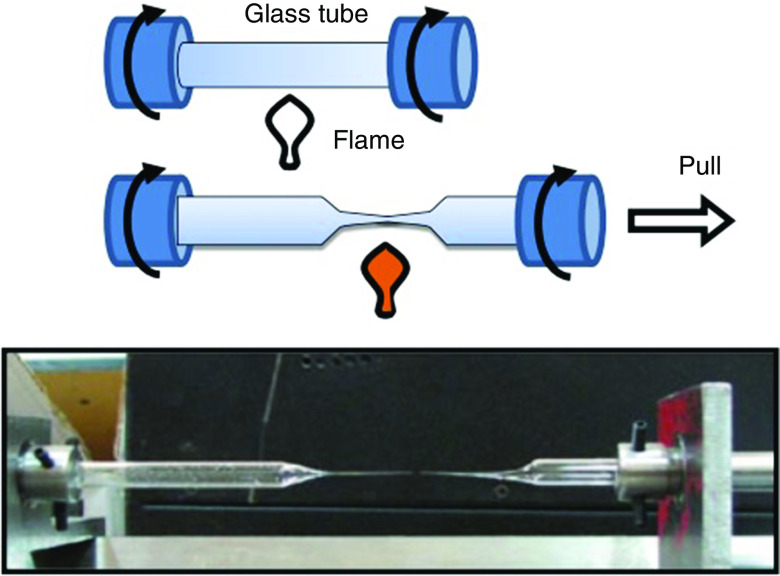
The data shown in Table II indicate that the droplets start to grow as they are ejected; in turn, their diameters are slightly higher than the inner diameters of the nozzle. In the piezoelectric actuators, the electric pulse shapes can be modified to control the droplet diameter and decrease the diameter of the ejected droplets.162,172 Reducing the size of the ejected droplets can be achieved by changing the printhead type.173 Efforts are under way to develop more precise methods of nozzle fabrication. The micro-electroforming method was one of the initial methods for nozzle fabrication.174,175 Photolithography has recently been used to fabricate nozzles for printers.176–178 Another creative fabrication method was proposed by Sadeghian et al., which involves fabrication of glass-based nozzles. They heated the center of a glass tube with a flame to a temperature that exceeds the glass transition temperature and pulled on the material from one side until the glass neck formed a sharp taper to fabricate the nozzle.179 They subsequently ground the tip of the nozzle to obtain the appropriate roundness tolerance and diameter. Figure 31 shows the schematic and image associated with this process. The nozzle tip must have appropriate surface properties to enhance printability; for example, increased wettability at the tip of the nozzle was associated with merging of droplets. This undesired phenomenon reduced the accuracy of the printer; it was addressed by applying a hydrophobic coating to the glass nozzle.179
FIG. 31.
Glass nozzle fabrication process. Reprinted with permission from Sadeghian et al., Int. J. Adv. Manuf. Technol. 70(5–8), 1091–1099 (2014).179 Copyright 2013 Springer Nature.
C. Actuator properties
Actuators are responsible for ejecting droplets in inkjet printers. These components are usually embedded at the nozzles on the printers to eject droplets from the nozzle by various mechanisms, including piezoelectric crystal actuation, electromagnetic forces, thermal actuation, and pneumatic pumps. Although each type of these actuators relies on a different mechanism, all of the actuator types have the same purpose, which is to overcome the ink surface tension and eject the droplets. Piezoelectric and thermal actuators are more commonly used; however, electromagnetic actuators have also been developed.126,180
The piezoelectric actuator is commonly used in 3D printers. The embedded piezoelectric crystal at the printhead of the inkjet printer converts an electric voltage to mechanical stress, which generates an acoustic wave to eject the ink from the nozzle. Control over this type of actuator is more straightforward than over other types of actuators. Thermal actuators are also used in 3D printing. These printers contain a small thin film heater in the fluid chamber. The direct contact of the ink and the heating source raises the ink temperature to produce and expand bubbles in the inks, causing ejection from the nozzle. The heating process in these actuators should be strong enough to generate bubbles. The heating process should also be regulated to reduce damage to the ink.161 In electromagnetic actuators, the pressure pulse is generated by an electromagnetic force. This type of actuator is suitable for printing metallic inks.126
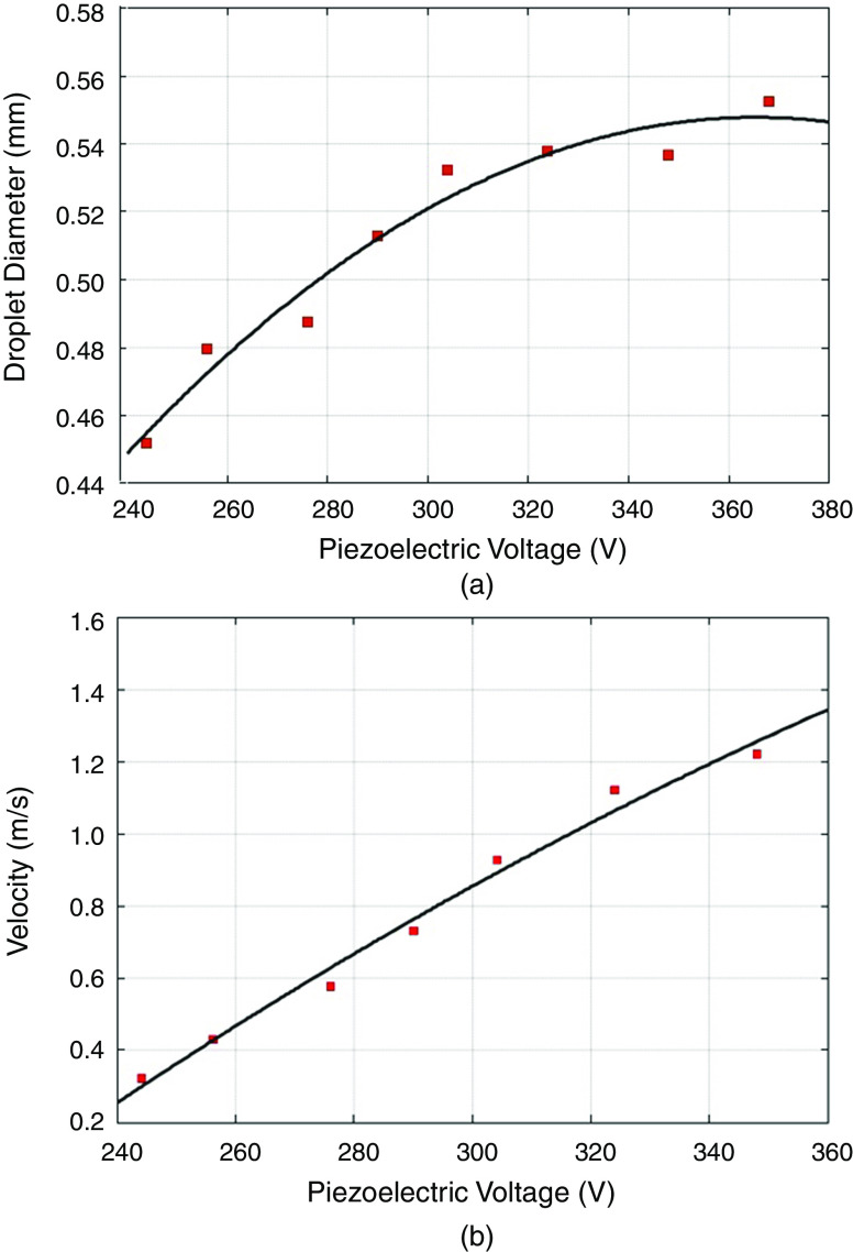
Piezoelectric actuators are commonly used for printing. Table III summarizes the design parameters of recent piezoelectric printers. These actuators convert the electric voltage to mechanical stress to accomplish droplet ejection. The shape of the electric pulses is the critical factor that affects the performance of these printers; this parameter is characterized by the applied voltage, the suction time, the compression time, and the signal frequency. Many studies have been carried out to understand the influence of the electric pulse on droplet generation. For example, the effects of voltage and the ratio of compression time and suction time have been investigated by Sadeghian et al.179 They showed that stronger voltages generated larger droplets. Higher intensities of electric voltage produced larger displacements of the diaphragm, produced stronger forces, and ejected larger droplets; it also increased the velocity of the droplet. Figure 32 shows the effect of the voltage amplitude on the droplet diameter and velocity.
FIG. 32.
Effect of voltage amplitude on (a) droplet diameter and (b) droplet velocity. When frequency = 250 Hz, nozzle diameter = 0.307 mm, and compression time/suction time = 0.26. Reprinted with permission from Sadeghian et al., Int. J. Adv. Manuf. Technol. 70(5–8), 1091–1099 (2014).179 Copyright 2013 Springer Nature.
There is a direct relationship between the excitation signal slope and the voltage amplitude. The diaphragm velocity increases along with the excitation signal slope. When a droplet leaves the nozzle, the local speed near the center is higher than at other locations. At higher voltage amplitudes, the breakoff length is longer, which leads to lower accuracy. Here, the breakoff length is defined as the elongation of the fluid before droplet formation. The elongation length defines the minimum distance between the nozzle and the substrate; shorter length results in higher accuracy.
An applied voltage of the range of 290 V to 339 V did not generate satellite droplets in the piezoelectric printer used in this study. However, the satellite droplets generated applied voltages of 339 V and 362 V. The satellites merged with the main droplet for voltages higher than 362 V. When the compression period is not sufficient, the droplets were unable to be ejected from the nozzle. An increase in the ratio of the compression time to the suction time resulted in larger ejected droplets. The longer compression time provided more time for the jet to exit the nozzle.179 The results of this study confirmed that the applied voltage should be precisely optimized to achieve the best performance in droplet generation and ejection. These two processes can be easily controlled by optimizing the electric pulse shape.
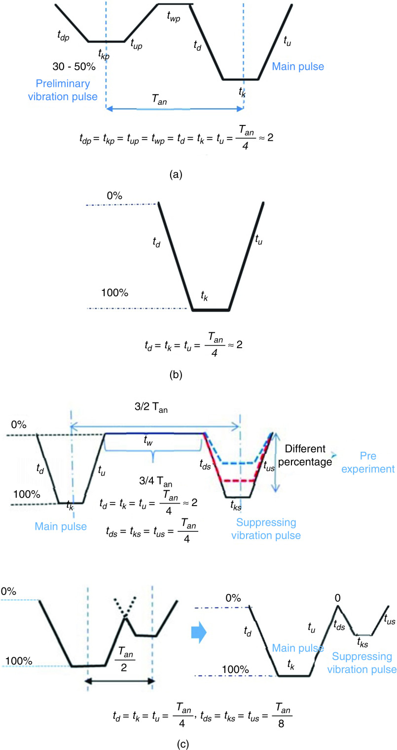
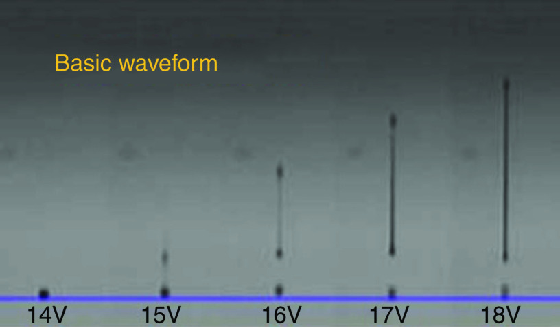
A complete understanding of drop formation is needed to improve the quality of the printing process. Oktavianty et al. developed an experimental setup to control the droplet formation process, droplet shape, droplet volume, and droplet velocity in inkjet printers by optimizing the waveform.181 The actual natural period of the inkjet printers ( ) can be used to determine the time parameters of the actuation pulse. Figure 33 explains recommendations for calculating the waveform parameters based on the natural period of the inkjet printer. Almost all of the droplet characteristics are influenced by the piezoelectric element actuating waveform. In order to optimize the piezoelectric actuating waveform performance, three different types of waveforms, including basic waveform, high-speed jetting waveform (bipolar waveform), and negative waveform, were studied; the optimum value of dwell time was then determined (Fig. 33). The waveform shape was optimized to achieve the best droplet generation process; moreover, the velocity and volume of the ejected droplets were optimized. Figure 34 illustrates how the intensity of the applied voltage modulates the generation of the ligament and satellites for the basic waveform voltage. Liu and Derby studied drop-on-demand inkjet behavior experimentally. Droplet behavior can be described by the dimensionless number Z, which is the inverse of the Ohnesorge number, and the Weber number of the fluid jet before formation of the droplet (Wej). By satisfying 2 < Wej < 25, stable drop generation can be obtained. Lower values are associated with the inhibition of drop ejection, and higher values lead to the onset of satellite drop formation. If Z < 50, by decreasing the Z, the critical value for Wej will increase because of viscous dissipation in drop formation. If Z ≈ 0.3, then droplet ejection is impossible. However, a large range for inks is able to form a droplet.182
FIG. 33.
Waveform profiles: A: Preliminary vibration, B: Basic waveform, and C: Suppressing vibration. Reprinted with permission from Oktavianty et al., Int. J. Mech. Aero. Ind. Mechatron. Manuf. Engineer. 11(4), 880–889 (2017).181
FIG. 34.
Droplet shape for basic waveform at 1000 from nozzle. Reprinted with permission from Oktavianty et al., Int. J. Mech. Aero. Ind. Mechatron. Manuf. Engineer. 11(4), 880–889 (2017).181
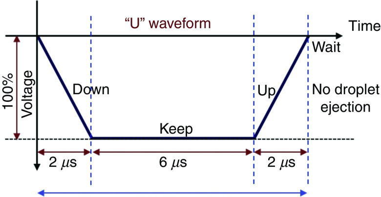
Prevention of ligaments or satellites, which are considered a significant limitation to inkjet printing, has been considered.183 A new actuation waveform was developed that could generate both single- and multi-droplet forms. Figure 35 demonstrates the proposed waveform and the ejected droplets. Ejection of droplets with no satellites or ligaments was achieved for up to five main pulses. This mechanism can be used to generate and eject different droplet sizes (e.g., five different droplet sizes) from the same nozzle by optimizing the waveform of the applied voltages. Their results showed that the printer is able to generate and eject droplets with appropriate shapes at an applied voltage between 14 V and 18 V. A preliminary vibration was applied to omit satellite and weeping features (see Fig. 35). These experimental results showed that preliminary vibration and a long dwell time are needed for multi-drop ejection. They calculated the dwell time without droplet ejection and demonstrated generation of a clear spherical droplet by applying the “U” shape waveform shown in Fig. 36.
FIG. 35.
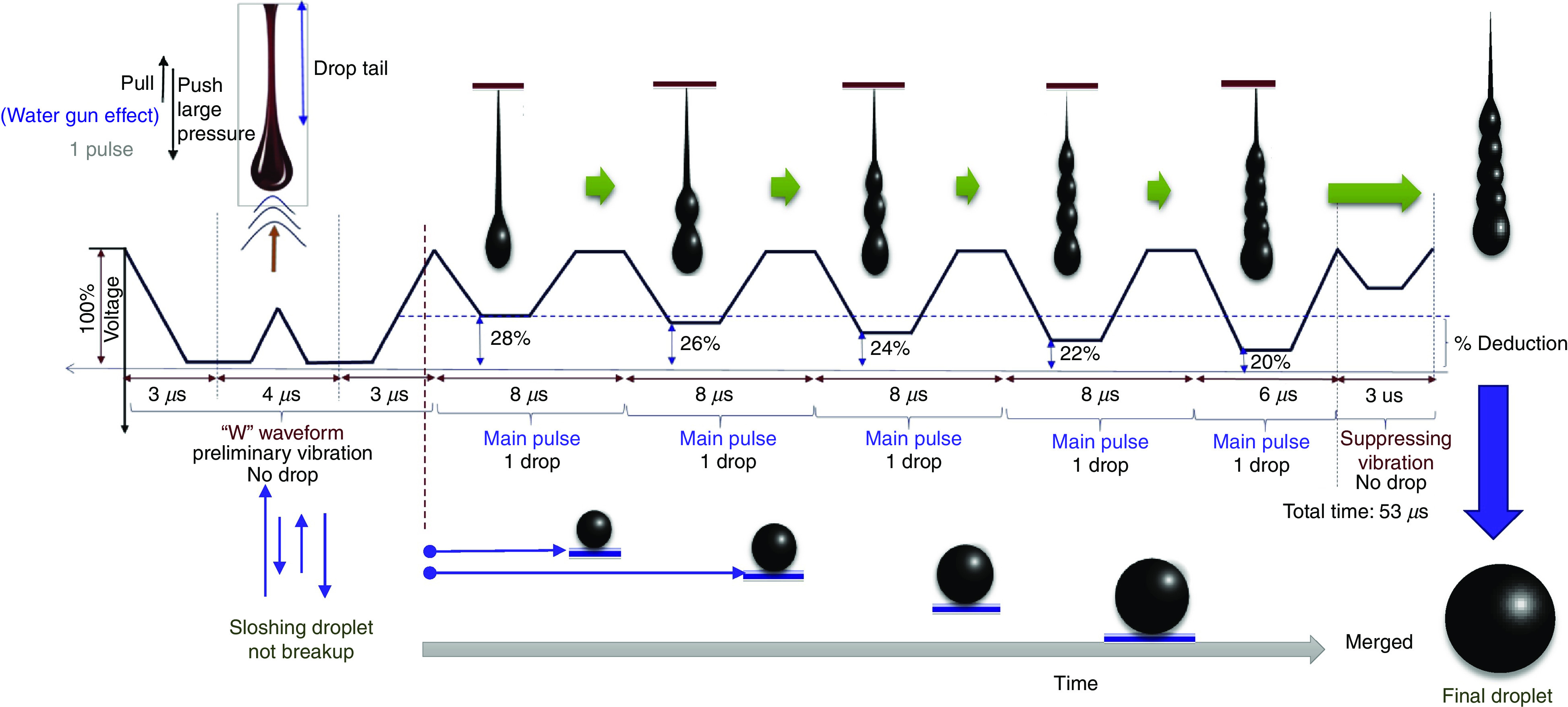
Conceptual drawing of multi-drop ejection. Reprinted with permission from Oktavianty et al., Add. Manuf. 25, 522–531 (2019).183 Copyright 2019 Elsevier.
FIG. 36.
“U” waveform profile as preliminary vibration. In this figure, = dwell time. Reprinted with permission from Oktavianty et al., Add. Manuf. 25, 522–531 (2019).183 Copyright 2019 Elsevier.
Snyder et al. proposed an ad hoc manual recalibration of the actuation waveform for various types of materials. This method does not use a large number of parameters for defining waveforms; however, it is not applicable to all waveforms. This method proposed an automatic waveform tuning method that includes: (a) overcoming the need for complex models by estimating drop velocity and volume measurement; (b) using algorithm-based stochastic optimization for tuning the waveform; and (c) enabling high order waveform exploration to increase the performance of the jetting system and material combination. The combination of computer vision detection of dispensed drops and global optimization of performance by algorithm was assessed. Control over drop volume and velocity were achieved at the same time.184
Chang et al. investigated the influences of the dwell time on the drop formation.185 Their results show that for a specific voltage and frequency, the droplet velocity increased the dwell time from zero to 24 . A further increase in the dwell time reduced the velocity. Their results also show that a droplet would not form for a dwell time longer than 42 . The study also showed that if the voltage is not strong enough to generate droplets, the meniscus oscillates at the nozzle and will not eject from the nozzle. They indicated that the optimal dwell time of l/c and 2 l/c is a good choice for ejecting drops when determining the excitation waveform; in these equations is the length of glass tube and is the effective sound speed in a glass tube.185
VII. CONCLUSIONS AND PERSPECTIVES ON FUTURE RESEARCH
There is a high demand in the medical and pharmaceutical industries for printed products that can be used in a variety of applications, including disease modeling, drug discovery, drug screening, and artificial tissues. One of the most common types of printers in the medical and pharmaceutical industries is the inkjet printer. Some of the unique advantages of inkjet printers include low cost, programmability, high resolution, high throughput nature, and high speed. Other advantages include the capability to fabricate artificial tissues with precise features; this capability has attracted attention in the medical and pharmaceutical industries. This review considered the recent developments in inkjet printing, including fundamental parameters of inkjet printing technology and recent studies involving the topic. We also discussed the effects of various engineering and design parameters such as ink viscosity, surface tension, printing parameters, and actuation mechanism.
Although this technology has recently been developed for medical and pharmaceutical applications, many restrictions need to be addressed to commercialize inkjet printing technology. As an example, new printers should be developed for printing inks containing living cells. In addition, more sophisticated inkjet printing procedures and inks should be developed for printing fragile drugs and cells.
The resolution of the inkjet printers should be enhanced to provide greater functionality and more precise printing outcomes. The chemical properties of the inks, mechanical properties of the inks, surface properties of the substrates, and the ink/substrate interactions should be optimized to enhance the resolution, printability, and uniformity of the printed structures. Advances in printing technology to reduce the vibration of printheads and increase the accuracy of droplet ejection will enhance the uniformity and resolution in the printed patterns. Finally, new inkjet printing technologies will need to meet national regulatory requirements in terms of printing uniformity prior to commercialization by the medical and pharmaceutical industries.
AUTHORS' CONTRIBUTIONS
All authors contributed equally to the work.
DATA AVAILABILITY
The data are available in the article or in the cited references.
References
- 1. Dawood A., Marti B. M., Sauret-Jackson V., and Darwood A., British Dental J. 219(11), 521 (2015). 10.1038/sj.bdj.2015.914 [DOI] [PubMed] [Google Scholar]
- 2. Tahayeri A., Morgan M., Fugolin A. P., Bompolaki D., Athirasala A., Pfeifer C. S., Ferracane J. L., and Bertassoni L. E., Dental Mater. 34(2), 192–200 (2018). 10.1016/j.dental.2017.10.003 [DOI] [PMC free article] [PubMed] [Google Scholar]
- 3. Almela T., Al-Sahaf S., Brook I. M., Khoshroo K., Rasoulianboroujeni M., Fahimipour F., Tahriri M., Dashtimoghadam E., Bolt R., and Tayebi L., Tissue Cell 52, 71–77 (2018). 10.1016/j.tice.2018.03.009 [DOI] [PubMed] [Google Scholar]
- 4. Hikita A., Chung U-i, Hoshi K., and Takato T., Tissue Eng. Part A 23(11–12), 515–521 (2017). 10.1089/ten.tea.2016.0543 [DOI] [PubMed] [Google Scholar]
- 5. Shah P. and Chong B., Clinical Oral Investigations 22(2), 1–14 (2018). [DOI] [PubMed] [Google Scholar]
- 6. Genina N., Holländer J., Jukarainen H., Mäkilä E., Salonen J., and Sandler N., Eur. J. Pharm. Sci. 90, 53–63 (2016). 10.1016/j.ejps.2015.11.005 [DOI] [PubMed] [Google Scholar]
- 7. Machekposhti S. A., Mohaved S., and Narayan R. J., Expert Opin. Drug Discovery 14(2), 101–113 (2019). 10.1080/17460441.2019.1567489 [DOI] [PMC free article] [PubMed] [Google Scholar]
- 8. Mazzocchi A., Soker S., and Skardal A., Appl. Phys. Rev. 6(1), 011302 (2019). 10.1063/1.5056188 [DOI] [PMC free article] [PubMed] [Google Scholar]
- 9. Ahadian S. and Khademhosseini A., Bio-Des. Manuf. 1(3), 157–160 (2018). 10.1007/s42242-018-0020-3 [DOI] [PMC free article] [PubMed] [Google Scholar]
- 10. Kolesky D. B., et al., PNAS 113(12), 3179–3184 (2016). [DOI] [PMC free article] [PubMed] [Google Scholar]
- 11. Ma X., Liu J., Zhu W., Tang M., Lawrence N., Yu C., Gou M., and Chen S., Adv. Drug Delivery Rev. 132, 235–251 (2018). 10.1016/j.addr.2018.06.011 [DOI] [PMC free article] [PubMed] [Google Scholar]
- 12. Mandrycky C., Wang Z., Kim K., and Kim D.-H., Biotechnol. Adv. 34(4), 422–434 (2016). 10.1016/j.biotechadv.2015.12.011 [DOI] [PMC free article] [PubMed] [Google Scholar]
- 13. Atapattu L., Utama R., O'Mahony A., Fife C., Baek J., Allard T., O'Mahony K., Ribeiro J., Gaus K., Gooding J., and Kavallaris M., “ Precision medicine: High-throughput 3D bioprinting of embedded multicellular cancer spheroids,” in Proceedings of the American Association for Cancer Research Annual Meeting 2018, April 14–18, 2018, Chicago, IL, Philadelphia (PA) (AACR, 2018), Cancer Res. 78(13), Suppl., Abstract No. 5022. 10.1158/1538-7445.AM2018-5022 [DOI] [Google Scholar]
- 14. Knowlton S., Onal S., Yu C. H., Zhao J. J., and Tasoglu S., Trends Biotechnol. 33(9), 504–513 (2015). 10.1016/j.tibtech.2015.06.007 [DOI] [PubMed] [Google Scholar]
- 15. Rodríguez-Dévora J. I., Bhuyan M., Reyna-Soriano D., and Boland T., J. Imaging Sci. Technol. 60(4), 404061 (2016). 10.2352/J.ImagingSci.Technol.2016.60.4.040406 [DOI] [Google Scholar]
- 16. Uddin M. J., Scoutaris N., Klepetsanis P., Chowdhry B., Prausnitz M. R., and Douroumis D., Int. J. Pharm. 494(2), 593–602 (2015). 10.1016/j.ijpharm.2015.01.038 [DOI] [PubMed] [Google Scholar]
- 17. Zhou X., Zhu W., Nowicki M., Miao S., Cui H., Holmes B., Glazer R. I., and Zhang L. G., ACS Appl. Mater. Interfaces 8(44), 30017–30026 (2016). 10.1021/acsami.6b10673 [DOI] [PubMed] [Google Scholar]
- 18. Zhu W., Holmes B., Glazer R. I., and Zhang L. G., Nanomedicine 12(1), 69–79 (2016). 10.1016/j.nano.2015.09.010 [DOI] [PubMed] [Google Scholar]
- 19. Albritton J. L. and Miller J. S., Disease Models Mechan. 10(1), 3–14 (2017). 10.1242/dmm.025049 [DOI] [PMC free article] [PubMed] [Google Scholar]
- 20. Nguyen D. G. and S. L. Pentoney, Jr. , Drug Discovery Today: Technol. 23, 37–44 (2017). 10.1016/j.ddtec.2017.03.001 [DOI] [PubMed] [Google Scholar]
- 21. van der Valk D. C., van der Ven C. F., Blaser M. C., Grolman J. M., Wu P.-J., Fenton O. S., Lee L. H., Tibbitt M. W., Andresen J. L., and Wen J. R., Nanomaterials 8(5), 296 (2018). 10.3390/nano8050296 [DOI] [PMC free article] [PubMed] [Google Scholar]
- 22. Zoltan S. I., U.S. patent US3683212A (1972).
- 23. Kyser E. L. and Sears S. B., U.S. patent US3946398A (1976).
- 24. Xu Q. and Basaran O. A., Phys. Fluids 19(10), 102111 (2007). 10.1063/1.2800784 [DOI] [Google Scholar]
- 25. Goole J. and Amighi K., Int. J. Pharm. 499(1–2), 376–394 (2016). 10.1016/j.ijpharm.2015.12.071 [DOI] [PubMed] [Google Scholar]
- 26. Goyanes A., Wang J., Buanz A., Martínez-Pacheco R., Telford R., Gaisford S., and Basit A. W., Mol. Pharm. 12(11), 4077–4084 (2015). 10.1021/acs.molpharmaceut.5b00510 [DOI] [PubMed] [Google Scholar]
- 27. Awad A., Trenfield S. J., Goyanes A., Gaisford S., and Basit A. W., Drug Discovery Today 23(8), 1547–1555 (2018). [DOI] [PubMed] [Google Scholar]
- 28. Lee H. and Cho D.-W., Lab a Chip 16(14), 2618–2625 (2016). 10.1039/C6LC00450D [DOI] [PubMed] [Google Scholar]
- 29. Zhang Y. S., Arneri A., Bersini S., Shin S.-R., Zhu K., Goli-Malekabadi Z., Aleman J., Colosi C., Busignani F., and Dell'Erba V., Biomaterials 110, 45–59 (2016). 10.1016/j.biomaterials.2016.09.003 [DOI] [PMC free article] [PubMed] [Google Scholar]
- 30. Sochol R. D., Gupta N. R., and Bonventre J. V., Curr. Transplant. Rep. 3(1), 82–92 (2016). 10.1007/s40472-016-0085-x [DOI] [PMC free article] [PubMed] [Google Scholar]
- 31. Bhise N. S., Manoharan V., Massa S., Tamayol A., Ghaderi M., Miscuglio M., Lang Q., Zhang Y. S., Shin S. R., and Calzone G., Biofabrication 8(1), 014101 (2016). 10.1088/1758-5090/8/1/014101 [DOI] [PubMed] [Google Scholar]
- 32. Yang Q., Lian Q., and Xu F., Biomicrofluidics 11(3), 031301 (2017). 10.1063/1.4982945 [DOI] [PMC free article] [PubMed] [Google Scholar]
- 33. Du J. and Liu X., BioMed Res. Int. 2017, 2123918. 10.1155/2017/2123918 [DOI] [PMC free article] [PubMed] [Google Scholar]
- 34. Tumey D. and Berriman S., U.S. patent US9545302B2 (2017).
- 35. Arenas M., Sabater S., Sintas A., Arguís M., Hernández V., Árquez M., López I., Rovirosa À., and Puig D., J. Contemp. Brachytherapy 3(3), 270 (2017). 10.5114/jcb.2017.68134 [DOI] [PMC free article] [PubMed] [Google Scholar]
- 36. Canters R., Lips I., Van Zeeland M., Kusters M., Wendling M., Gerritsen R., Poortmans P., and Verhoef C., Radiotherapy Oncol. 119, S134 (2016). 10.1016/S0167-8140(16)31535-3 [DOI] [PubMed] [Google Scholar]
- 37. Canters R. A., Lips I. M., Wendling M., Kusters M., van Zeeland M., Gerritsen R. M., Poortmans P., and Verhoef C. G., Radiotherapy Oncol. 121(1), 148–153 (2016). 10.1016/j.radonc.2016.07.011 [DOI] [PubMed] [Google Scholar]
- 38. Bhattacharyya S., Kaes D. R., Wei G., and Mistry A., U.S. patent US20180303616A1 (2018).
- 39. Kurian M., Stevens R., and McGrath K. M., J. Funct. Biomat. 10(1), 12 (2019). 10.3390/jfb10010012 [DOI] [PMC free article] [PubMed] [Google Scholar]
- 40. Oladapo B. I., Zahedi S. A., and Adeoye A. O. M., Composites Part B: Eng. 158, 428–436 (2018). 10.1016/j.compositesb.2018.09.065 [DOI] [Google Scholar]
- 41. Bose S., Robertson S. F., and Bandyopadhyay A., Am. Scientist 106(2), 112–119 (2018). 10.1511/2018.106.2.112 [DOI] [Google Scholar]
- 42. Nagarajan N., Dupret-Bories A., Karabulut E., Zorlutuna P., and Vrana N. E., Biotechnol. Adv. 36(2), 521–533 (2018). 10.1016/j.biotechadv.2018.02.004 [DOI] [PubMed] [Google Scholar]
- 43. Lin J., Zhou Z., Guan J., Zhu Y., Liu Y., Yang Z., Lin B., Jiang Y., Quan X., and Ke Y., World Neurosurg. 120, e142–e152 (2018). 10.1016/j.wneu.2018.07.236 [DOI] [PubMed] [Google Scholar]
- 44. Zhang H., Liu G., Tong X. G., and Hang W., J. Otorhinolaryngol. Head Neck Surg. 53(10), 780–784 (2018). 10.3760/cma.j.issn.1673-0860.2018.10.012 [DOI] [PubMed] [Google Scholar]
- 45. Essayed W. I., Unadkat P., Hosny A., Frisken S., Rassi M. S., Mukundan S., Weaver J. C., Al-Mefty O., Golby A. J., and Dunn I. F., J. Neurosurg. 130(1), 248–255 (2018). 10.3171/2017.9.JNS171253 [DOI] [PMC free article] [PubMed] [Google Scholar]
- 46. Chiu A. S., Arnold B. N., Hoag J. R., Herrin J., Kim C. H., Salazar M. C., Monsalve A. F. et al. , Ann. Surg. 270(2), 281–287 (2019). 10.1097/SLA.0000000000002762 [DOI] [PubMed] [Google Scholar]
- 47. Kim S. H., Lee S. J., Lee J. W., Jeong H. S., and Suh I. S., Medicine 98(6), e13864 (2019). 10.1097/MD.0000000000013864 [DOI] [PMC free article] [PubMed] [Google Scholar]
- 48. Kalberer N., Mehl A., Schimmel M., Müller F., and Srinivasan M., J. Prosthetic Dentistry 121(4), 637–643 (2019). 10.1016/j.prosdent.2018.09.001 [DOI] [PubMed] [Google Scholar]
- 49. Tasopoulos T., Chatziemmanouil D., Karaiskou G., Kouveliotis G., Wang J., and Zoidis P., J. Prosthetic Dentistry 121(6), 960–963 (2019). 10.1016/j.prosdent.2018.10.004 [DOI] [PubMed] [Google Scholar]
- 50. Groth C., Kravitz N. D., and Shirck J. M., J. Clin. Orthod. 52(1), 28–33 (2018), see http://www.kravitzorthodontics.com/assets/pdfs/Incorporating_Three-Dimensional_Printing_in_Orthodontics.pdf. [PubMed] [Google Scholar]
- 51. Short M. M., Favero C. S., English J. D., and Kasper F. K., J. Clin. Orthod. 52(1), 13 (2018), see https://pubmed.ncbi.nlm.nih.gov/29447126/. [PubMed] [Google Scholar]
- 52. Juneja M., Thakur N., Kumar D., Gupta A., Bajwa B., and Jindal P., Addit. Manuf. 22, 243–255 (2018). 10.1016/j.addma.2018.05.012 [DOI] [Google Scholar]
- 53. Anderson J., Wealleans J., and Ray J., Int. Endo. J. 51(9), 1005–1018 (2018). 10.1111/iej.12917 [DOI] [PubMed] [Google Scholar]
- 54. Duan B., Hockaday L. A., Kang K. H., and Butcher J. T., J. Biomed. Mater. Res. Part A 101A(5), 1255–1264 (2013). 10.1002/jbm.a.34420 [DOI] [PMC free article] [PubMed] [Google Scholar]
- 55. Duan B., Ann. Biomed. Engineer. 45(1), 195–209 (2017). 10.1007/s10439-016-1607-5 [DOI] [PubMed] [Google Scholar]
- 56. Kuss M. and Duan B., in Rapid Prototyping in Cardiac Disease ( Springer, 2017), pp. 167–182. [Google Scholar]
- 57. Lee A. and Feinberg A. W., in 3D Bioprinting in Regenerative Engineering: Principles and Applications ( Routledge, 2018), pp. 203–206. [Google Scholar]
- 58. Hu J. B., Tomov M. L., Buikema J. W., Chen C., Mahmoudi M., Wu S. M., and Serpooshan V., Appl. Phys. Rev. 5(4), 041106 (2018). 10.1063/1.5048807 [DOI] [PMC free article] [PubMed] [Google Scholar]
- 59. Chang R., Emami K., Wu H., and Sun W., Biofabrication 2(4), 045004 (2010). 10.1088/1758-5082/2/4/045004 [DOI] [PubMed] [Google Scholar]
- 60. Javan R., Herrin D., and Tangestanipoor A., Academ Radiol. 23(9), 1183–1189 (2016). 10.1016/j.acra.2016.04.010 [DOI] [PubMed] [Google Scholar]
- 61. Wang L., Cao T., Li X., and Huang L., J. Thoracic Cardiovasc. Surg. 152(1), e5–e7 (2016). 10.1016/j.jtcvs.2016.02.064 [DOI] [PubMed] [Google Scholar]
- 62. Mirza A. A., Robinson T. E., Gifford K., and Guo H. H., J. Cystic Fibrosis 18(2), 278–279 (2018). [DOI] [PubMed] [Google Scholar]
- 63. Dzobo K., Senthebane D. A., Ganz C., Thomford N. E., Wonkam A., and Dandara C., Cells 9(8), 1896 (2020). 10.3390/cells9081896 [DOI] [PMC free article] [PubMed] [Google Scholar]
- 64. Tran-Gia J., Schlögl S., and Lassmann M., J. Nucl. Med. 57(12), 1998–2005 (2016). 10.2967/jnumed.116.178046 [DOI] [PubMed] [Google Scholar]
- 65. Huang Y.-Z., Hsieh J.-W., Lee C.-H., Chen Y., and Chuang P.-J., Presented at the 2018 1st International Cognitive Cities Conference (IC3), 2018. (unpublished). [Google Scholar]
- 66. Denizet G., Calame P., Lihoreau T., Kleinclauss F., and Aubry S., Quant. Imag. Med. Surg. 9(1), 101 (2019). 10.21037/qims.2018.10.16 [DOI] [PMC free article] [PubMed] [Google Scholar]
- 67. Liu H., Zhou H., Lan H., Liu T., Liu X., and Yu H., Micromachines 8(8), 237 (2017). 10.3390/mi8080237 [DOI] [PMC free article] [PubMed] [Google Scholar]
- 68. Liu J., Zheng H., Krempl F., Su L., Machens H.-G., and Schilling A. F., 3D Printing Addit. Manuf. 3(1), 22–31 (2016). 10.1089/3dp.2015.0025 [DOI] [Google Scholar]
- 69. Silbert R., Buse D. A., Rosati R. J., Tammer O., and Merten M., U.S. patent US20180292427A1 (2018).
- 70. Pietrzak K., Isreb A., and Alhnan M. A., Eur. J. Pharm. Biopharm. 96, 380–387 (2015). 10.1016/j.ejpb.2015.07.027 [DOI] [PubMed] [Google Scholar]
- 71. Skowyra J., Pietrzak K., and Alhnan M. A., Eur. J. Pharm. Sci. 68, 11–17 (2015). 10.1016/j.ejps.2014.11.009 [DOI] [PubMed] [Google Scholar]
- 72. Gupta S., Webster T. J., and Sinha A., J. Mater. Sci.: Mater. Med. 22(7), 1763–1772 (2011). 10.1007/s10856-011-4343-2 [DOI] [PubMed] [Google Scholar]
- 73. Goyanes A., Det-Amornrat U., Wang J., Basit A. W., and Gaisford S., J. Controlled Release 234, 41–48 (2016). 10.1016/j.jconrel.2016.05.034 [DOI] [PubMed] [Google Scholar]
- 74. Zein I., Hutmacher D. W., Tan K. C., and Teoh S. H., Biomaterials 23(4), 1169–1185 (2002). 10.1016/S0142-9612(01)00232-0 [DOI] [PubMed] [Google Scholar]
- 75. Pati F., Jang J., Lee J. W., and Cho D.-W., in Essentials of 3D Biofabrication and Translation ( Elsevier, 2015), pp. 123–152. [Google Scholar]
- 76. Shafranek R. T., Millik S. C., Smith P. T., Lee C.-U., Boydston A. J., and Nelson A., Prog. Polym. Sci. 93, 36–67 (2019). 10.1016/j.progpolymsci.2019.03.002 [DOI] [Google Scholar]
- 77. Griffin E. A. and McMillin S., Presented at the 1995 International Solid Freeform Fabrication Symposium, 1995. (unpublished). [Google Scholar]
- 78. Wang J., Goyanes A., Gaisford S., and Basit A. W., Int. J. Pharm. 503(1–2), 207–212 (2016). 10.1016/j.ijpharm.2016.03.016 [DOI] [PubMed] [Google Scholar]
- 79. Wang Z., Tian Z., Jin X., Holzman J. F., Menard F., and Kim K., Presented at the Engineering in Medicine and Biology Society (EMBC), 2017 39th Annual International Conference of the IEEE, 2017. (unpublished). [Google Scholar]
- 80. Raman R. and Bashir R., in Essentials of 3D Biofabrication and Translation ( Elsevier, 2015), pp. 89–121. [Google Scholar]
- 81. Schiele N. R., Corr D. T., Huang Y., Raof N. A., Xie Y., and Chrisey D. B., Biofabrication 2(3), 032001 (2010). 10.1088/1758-5082/2/3/032001 [DOI] [PMC free article] [PubMed] [Google Scholar]
- 82. Melchels F. P., Feijen J., and Grijpma D. W., Biomaterials 31(24), 6121–6130 (2010). 10.1016/j.biomaterials.2010.04.050 [DOI] [PubMed] [Google Scholar]
- 83. Chan V., Zorlutuna P., Jeong J. H., Kong H., and Bashir R., Lab a Chip 10(16), 2062–2070 (2010). 10.1039/c004285d [DOI] [PubMed] [Google Scholar]
- 84. Vehse M., Petersen S., Sternberg K., Schmitz K. P., and Seitz H., Presented at the Macromolecular Symposia, 2014. (unpublished). [Google Scholar]
- 85. Hanson Shepherd J. N., Parker S. T., Shepherd R. F., Gillette M. U., Lewis J. A., and Nuzzo R. G., Adv. Funct. Mater. 21(1), 47–54 (2011). 10.1002/adfm.201001746 [DOI] [PMC free article] [PubMed] [Google Scholar]
- 86. Arcaute K., Mann B. K., and Wicker R. B., Ann. Biomed. Engineer. 34(9), 1429–1441 (2006). 10.1007/s10439-006-9156-y [DOI] [PubMed] [Google Scholar]
- 87. Dhariwala B., Hunt E., and Boland T., Tissue Engineer. 10(9–10), 1316–1322 (2004). 10.1089/ten.2004.10.1316 [DOI] [PubMed] [Google Scholar]
- 88. Fisher J. P., Dean D., and Mikos A. G., Biomaterials 23(22), 4333–4343 (2002). 10.1016/S0142-9612(02)00178-3 [DOI] [PubMed] [Google Scholar]
- 89. Gittard S. D., Nguyen A., Obata K., Koroleva A., Narayan R. J., and Chichkov B. N., Biomed. Optics Exp. 2(11), 3167–3178 (2011). 10.1364/BOE.2.003167 [DOI] [PMC free article] [PubMed] [Google Scholar]
- 90. Gittard S. D., Ovsianikov A., Chichkov B. N., Doraiswamy A., and Narayan R. J., Expert Opin. Drug Delivery 7(4), 513–533 (2010). 10.1517/17425241003628171 [DOI] [PMC free article] [PubMed] [Google Scholar]
- 91. Zhang A. P., Qu X., Soman P., Hribar K. C., Lee J. W., Chen S., and He S., Adv. Mater. 24(31), 4266–4270 (2012). 10.1002/adma.201202024 [DOI] [PMC free article] [PubMed] [Google Scholar]
- 92. Emami M. M., Barazandeh F., and Yaghmaie F., J. Mater. Process. Technol. 219, 17–27 (2015). 10.1016/j.jmatprotec.2014.12.001 [DOI] [Google Scholar]
- 93. Gauvin R., Chen Y.-C., Lee J. W., Soman P., Zorlutuna P., Nichol J. W., Bae H., Chen S., and Khademhosseini A., Biomaterials 33(15), 3824–3834 (2012). 10.1016/j.biomaterials.2012.01.048 [DOI] [PMC free article] [PubMed] [Google Scholar]
- 94. Corbel S., Dufaud O., and Roques-Carmes T., in Stereolithography ( Springer, 2011), pp. 141–159. [Google Scholar]
- 95. Klebe R. J., Exp. Cell Res. 179(2), 362–373 (1988). 10.1016/0014-4827(88)90275-3 [DOI] [PubMed] [Google Scholar]
- 96. Lee V. K. and Dai G., Ann. Biomed. Engineer. 45(1), 115–131 (2017). 10.1007/s10439-016-1613-7 [DOI] [PMC free article] [PubMed] [Google Scholar]
- 97. Peng W., Datta P., Ayan B., Ozbolat V., Sosnoski D., and Ozbolat I. T., Acta Biomaterialia 57, 26–46 (2017). 10.1016/j.actbio.2017.05.025 [DOI] [PubMed] [Google Scholar]
- 98. Prasad L. K. and Smyth H., Drug Develop. Ind. Pharm. 42(7), 1019–1031 (2016). 10.3109/03639045.2015.1120743 [DOI] [PubMed] [Google Scholar]
- 99. Uhland S., Holman R., Cima M., Sachs E., and Enokido Y., MRS Online Proceedings Library Archive 542 (1998). [Google Scholar]
- 100. Michaels S., Sachs E. M., and Cima M. J., Presented at the 1992 International Solid Freeform Fabrication Symposium, 1992. (unpublished). [Google Scholar]
- 101. Lauder A., Cima M., Sachs E., and Fan T., MRS Online Proceedings Library Archive 249 (1991). [Google Scholar]
- 102. Daly R., Harrington T. S., Martin G. D., and Hutchings I. M., Int. J. Pharm. 494(2), 554–567 (2015). 10.1016/j.ijpharm.2015.03.017 [DOI] [PubMed] [Google Scholar]
- 103. Chameettachal S. and Pati F., in 3D Bioprinting in Regenerative Engineering: Principles and Applications ( Routledge, 2018), pp. 344–346. [Google Scholar]
- 104. Wu D. and Xu C., J. Manuf. Sci. Eng. 140(10), 101007 (2018). 10.1115/1.4040619 [DOI] [Google Scholar]
- 105. Chen P.-H., Chen W.-C., Ding P.-P., and Chang S., Int. J. Heat Fluid Flow 19(4), 382–390 (1998). 10.1016/S0142-727X(98)10007-3 [DOI] [Google Scholar]
- 106. Liu Y.-F., Tsai M.-H., Pai Y.-F., and Hwang W.-S., Appl. Phys. A 111(2), 509–516 (2013). 10.1007/s00339-013-7569-7 [DOI] [Google Scholar]
- 107. Chen Y.-S., Huang Y.-L., Kuo C.-H., and Chang S.-H., Int. J. Mech. Sci. 49(6), 733–740 (2007). 10.1016/j.ijmecsci.2006.10.004 [DOI] [Google Scholar]
- 108. Shin D.-Y., Grassia P., and Derby B., Int. J. Mech. Sci. 46(2), 181–199 (2004). 10.1016/j.ijmecsci.2004.03.008 [DOI] [Google Scholar]
- 109. Dadvand A., Shervani-Tabar M. T., and Khoo B. C., Int. J. Adv. Manuf. Technol. 56(1–4), 245–259 (2011). 10.1007/s00170-011-3165-1 [DOI] [Google Scholar]
- 110. Cheng H.-P. and Chiu M.-L., Numer. Heat Transfer, Part A: Appl. 52(9), 777–793 (2007). 10.1080/10407780701348273 [DOI] [Google Scholar]
- 111. Jo B. W., Lee A., Ahn K. H., and Lee S. J., Korean J. Chem. Eng. 26(2), 339–348 (2009). 10.1007/s11814-009-0057-2 [DOI] [Google Scholar]
- 112. Link N., Lampert S., Gurka R., Liberzon A., Hetsroni G., and Semiat R., Chem. Eng. Process.: Process Intensification 48(1), 84–91 (2009). 10.1016/j.cep.2008.02.006 [DOI] [Google Scholar]
- 113. Xu C., Zhang M., Huang Y., Ogale A., Fu J., and Markwald R. R., Langmuir 30(30), 9130–9138 (2014). 10.1021/la501430x [DOI] [PubMed] [Google Scholar]
- 114. Waghmare P. R. and Mitra S. K., Langmuir 26(22), 17082–17089 (2010). 10.1021/la1025526 [DOI] [PubMed] [Google Scholar]
- 115. Derby B., J. Mater. Chem. 18(47), 5717–5721 (2008). 10.1039/b807560c [DOI] [Google Scholar]
- 116. Shin P., Sung J., and Lee M. H., Microelectron. Rel. 51(4), 797–804 (2011). 10.1016/j.microrel.2010.11.017 [DOI] [Google Scholar]
- 117. Gan H., Shan X., Eriksson T., Lok B., and Lam Y., J. Micromech. Microeng. 19(5), 055010 (2009). 10.1088/0960-1317/19/5/055010 [DOI] [Google Scholar]
- 118. Kim B.-H., Kim S.-I., Lee J.-C., Shin S.-J., and Kim S.-J., Sens. Actuators A: Phys. 173(1), 244–253 (2012). 10.1016/j.sna.2011.10.010 [DOI] [Google Scholar]
- 119. Lin H.-J., Wu H.-C., Shan T.-R., and Hwang W.-S., Mater. Trans. 47(2), 375–382 (2006). 10.2320/matertrans.47.375 [DOI] [Google Scholar]
- 120. Dong H., Carr W. W., and Morris J. F., Phys. Fluids 18(7), 072102 (2006). 10.1063/1.2217929 [DOI] [Google Scholar]
- 121. Hoath S. D., Fundamentals of Inkjet Printing: The Science of Inkjet and Droplets. ( John Wiley & Sons, 2016). [Google Scholar]
- 122. Xu C., Huang Y., Fu J., and Markwald R. R., J. Micromech. Microeng. 24(11), 115011 (2014). 10.1088/0960-1317/24/11/115011 [DOI] [PMC free article] [PubMed] [Google Scholar]
- 123. Onses M. S., Sutanto E., Ferreira P. M., Alleyne A. G., and Rogers J. A., Small 11(34), 4237–4266 (2015). 10.1002/smll.201500593 [DOI] [PubMed] [Google Scholar]
- 124. Workman V. L., Tezera L. B., Elkington P. T., and Jayasinghe S. N., Adv. Funct. Mater. 24(18), 2648–2657 (2014). 10.1002/adfm.201303891 [DOI] [PMC free article] [PubMed] [Google Scholar]
- 125. Gudapati H., Dey M., and Ozbolat I., Biomaterials 102, 20–42 (2016). 10.1016/j.biomaterials.2016.06.012 [DOI] [PubMed] [Google Scholar]
- 126. Wang T., Lin J., Lei Y., Guo X., Fu H., and Zhang N., Vacuum 156, 128–134 (2018). 10.1016/j.vacuum.2018.07.019 [DOI] [Google Scholar]
- 127. Du W. and Chaudhuri S., Int. J. Multiphase Flow 90, 46–56 (2017). 10.1016/j.ijmultiphaseflow.2016.11.009 [DOI] [Google Scholar]
- 128. Jung E. M., Lee S. W., and Kim S. H., Organic Electron. 52, 123–129 (2018). 10.1016/j.orgel.2017.10.013 [DOI] [Google Scholar]
- 129. Li B., Fan J., Li J., Chu J., and Pan T., Biomicrofluidics 9(5), 054101 (2015). 10.1063/1.4928298 [DOI] [PMC free article] [PubMed] [Google Scholar]
- 130. Minov S. V., Cointault F., Vangeyte J., Pieters J. G., and Nuyttens D., Crop Protection 69, 18–27 (2015). 10.1016/j.cropro.2014.11.012 [DOI] [Google Scholar]
- 131. Li K., Liu J.-K., Chen W.-S., and Zhang L., IEEE Access 6, 25930–25938 (2018). 10.1109/ACCESS.2018.2820902 [DOI] [Google Scholar]
- 132. Li K., Liu J-k, Yang R., Chen W.-s., and Zhang L., Ceram. Int. 43, S27–S35 (2017). 10.1016/j.ceramint.2017.05.200 [DOI] [Google Scholar]
- 133. Shin D.-Y., Yoo S.-S., Song H-e, Tak H., and Byun D., Sci. Rep. 5, 16704 (2015). 10.1038/srep16704 [DOI] [PMC free article] [PubMed] [Google Scholar]
- 134. Stringer J. and Derby B., J. Eur. Ceram. Soc. 29(5), 913–918 (2009). 10.1016/j.jeurceramsoc.2008.07.016 [DOI] [Google Scholar]
- 135. Planchette C., Pichler H., Wimmer-Teubenbacher M., Gruber M., Gruber-Wölfler H., Mohr S., Tetyczka C., Hsiao W.-K., Paudel A., and Roblegg E., Int. J. Pharm. 509(1–2), 518–527 (2016). 10.1016/j.ijpharm.2015.10.054 [DOI] [PubMed] [Google Scholar]
- 136. Stow C. and Stainer R., J. Meteorolog. Soc. Jpn. 55(5), 518–531 (1977). 10.2151/jmsj1965.55.5_518 [DOI] [Google Scholar]
- 137. Pegg M., Purvis R., and Korobkin A., J. Fluid Mech. 839, 561–593 (2018). 10.1017/jfm.2018.60 [DOI] [Google Scholar]
- 138. Genina N., Janßen E. M., Breitenbach A., Breitkreutz J., and Sandler N., Eur. J. Pharm. Biopharm. 85(3), 1075–1083 (2013). 10.1016/j.ejpb.2013.03.017 [DOI] [PubMed] [Google Scholar]
- 139. Ko H.-Y., Park J., Shin H., and Moon J., Chem. Mater. 16(22), 4212–4215 (2004). 10.1021/cm035256t [DOI] [Google Scholar]
- 140. Wang J., Zheng Z., Li H., Huck W., and Sirringhaus H., Nat. Mater. 3(3), 171 (2004). 10.1038/nmat1073 [DOI] [PubMed] [Google Scholar]
- 141. Li Z., Wang J., Zhang Y., Wang J., Jiang L., and Song Y., Appl. Phys. Lett. 97(23), 233107 (2010). 10.1063/1.3527076 [DOI] [Google Scholar]
- 142. Hendriks C. E., Smith P. J., Perelaer J., Van den Berg A. M., and Schubert U. S., Adv. Funct. Mater. 18(7), 1031–1038 (2008). 10.1002/adfm.200601062 [DOI] [Google Scholar]
- 143. Lee B. K., Yun Y. H., Choi J. S., Choi Y. C., Kim J. D., and Cho Y. W., Int. J. Pharm. 427(2), 305–310 (2012). 10.1016/j.ijpharm.2012.02.011 [DOI] [PubMed] [Google Scholar]
- 144. Latka A., Strandburg-Peshkin A., Driscoll M. M., Stevens C. S., and Nagel S. R., Phys. Rev. Lett. 109(5), 054501 (2012). 10.1103/PhysRevLett.109.054501 [DOI] [PubMed] [Google Scholar]
- 145. Bolleddula D., Berchielli A., and Aliseda A., Adv. Colloid Interface Sci. 159(2), 144–159 (2010). 10.1016/j.cis.2010.06.003 [DOI] [PubMed] [Google Scholar]
- 146. Kuang M., Wang L., and Song Y., Adv. Mater. 26(40), 6950–6958 (2014). 10.1002/adma.201305416 [DOI] [PubMed] [Google Scholar]
- 147. Deegan R. D., Bakajin O., Dupont T. F., Huber G., Nagel S. R., and Witten T. A., Nature 389(6653), 827 (1997). 10.1038/39827 [DOI] [Google Scholar]
- 148. Oh Y., Kim J., Yoon Y. J., Kim H., Yoon H. G., Lee S.-N., and Kim J., Curr. Appl. Phys. 11(3), S359–S363 (2011). 10.1016/j.cap.2010.11.065 [DOI] [Google Scholar]
- 149. Kajiya T., Kobayashi W., Okuzono T., and Doi M., Langmuir 26(13), 10429–10432 (2010). 10.1021/la1016388 [DOI] [PubMed] [Google Scholar]
- 150. Park J. S., Kim J. P., Song C., and Lee M., Displays 31(3), 164–167 (2010). 10.1016/j.displa.2010.04.004 [DOI] [Google Scholar]
- 151. Tekin E., de Gans B.-J., and Schubert U. S., J. Mater. Chem. 14(17), 2627–2632 (2004). 10.1039/b407478e [DOI] [Google Scholar]
- 152. Hu H. and Larson R. G., J. Phys. Chem. B 110(14), 7090–7094 (2006). 10.1021/jp0609232 [DOI] [PubMed] [Google Scholar]
- 153. Zhou J. X., Fuh J. Y., Loh H. T., San Wong Y., Ng Y. S., Gray J. J., and Chua S. J., Int. J. Adv. Manuf. Technol. 48(1–4), 243–250 (2010). 10.1007/s00170-009-2274-6 [DOI] [Google Scholar]
- 154. Sempels W., De Dier R., Mizuno H., Hofkens J., and Vermant J., Nat. Commun. 4(1), 1–8 (2013). 10.1038/ncomms2746 [DOI] [PMC free article] [PubMed] [Google Scholar]
- 155. Soltman D. and Subramanian V., Langmuir 24(5), 2224–2231 (2008). 10.1021/la7026847 [DOI] [PubMed] [Google Scholar]
- 156. Lim J. A., Lee W. H., Lee H. S., Lee J. H., Park Y. D., and Cho K., Adv. Funct. Mater. 18(2), 229–234 (2008). 10.1002/adfm.200700859 [DOI] [Google Scholar]
- 157. Chameettachal S. and Pati F., 3D Bioprinting in Regenerative Engineering: Principles and Applications, 100–120 (2018).
- 158. Abedini H., Movahed S., and Abolfathi N., J. Mech. Med. Biol. 15(05), 1550065 (2015). 10.1142/S0219519415500657 [DOI] [Google Scholar]
- 159. Hutchings I. M. and Martin G. D., Inkjet Technology for Digital Fabrication. ( John Wiley & Sons, 2012). [Google Scholar]
- 160. Saunders R. E. and Derby B., Int. Mater. Rev. 59(8), 430–448 (2014). 10.1179/1743280414Y.0000000040 [DOI] [Google Scholar]
- 161. Derby B., Annu. Rev. Mater. Res. 40, 395–414 (2010). 10.1146/annurev-matsci-070909-104502 [DOI] [Google Scholar]
- 162. Delrot P., Modestino M. A., Gallaire F., Psaltis D., and Moser C., Phys. Rev. Appl. 6(2), 024003 (2016). 10.1103/PhysRevApplied.6.024003 [DOI] [Google Scholar]
- 163. Duocastella M., Patrascioiu A., Fernández-Pradas J. M., Morenza J., and Serra P., Opt. Express 18(21), 21815–21825 (2010). 10.1364/OE.18.021815 [DOI] [PubMed] [Google Scholar]
- 164. Lee T., Baac H. W., Ok J. G., Youn H. S., and Guo L. J., Phys. Rev. Appl. 3(4), 044007 (2015). 10.1103/PhysRevApplied.3.044007 [DOI] [Google Scholar]
- 165. Munaz A., Vadivelu R. K., John J. S., Barton M., Kamble H., and Nguyen N.-T., J. Sci.: Adv. Mater. Devices 1(1), 1–17 (2016). 10.1016/j.jsamd.2016.04.001 [DOI] [Google Scholar]
- 166. Hoch E., Hirth T., Tovar G. E., and Borchers K., J. Mater. Chem. B 1(41), 5675–5685 (2013). 10.1039/c3tb20745e [DOI] [PubMed] [Google Scholar]
- 167. Piras C. C., Fernández-Prieto S., and De Borggraeve W. M., Biomate. Sci. 5(10), 1988–1992 (2017). 10.1039/C7BM00510E [DOI] [PubMed] [Google Scholar]
- 168. Yin J., Yan M., Wang Y., Fu J., and Suo H., ACS Appl. Mater. Interfaces 10(8), 6849–6857 (2018). 10.1021/acsami.7b16059 [DOI] [PubMed] [Google Scholar]
- 169. Groll J., Burdick J., Cho D., Derby B., Gelinsky M., Heilshorn S., Jüngst T., Malda J., Mironov V., and Nakayama K., Biofabrication 11(1), 013001 (2018). 10.1088/1758-5090/aaec52 [DOI] [PubMed] [Google Scholar]
- 170. Shinjo J. and Umemura A., Int. J. Multiphase Flow 36(7), 513–532 (2010). 10.1016/j.ijmultiphaseflow.2010.03.008 [DOI] [Google Scholar]
- 171. Ashrafi Z., Lucia L., and Krause W., Soft Matter 15(45), 9359–9367 (2019). 10.1039/C9SM01895F [DOI] [PubMed] [Google Scholar]
- 172. Vaughn B. S., Tracey P. J., and Trevitt A. J., RSC Adv. 6(65), 60215–60222 (2016). 10.1039/C6RA08472A [DOI] [Google Scholar]
- 173. Lee V. K., Dias A., Ozturk M. S., Chen K., Tricomi B., Corr D. T., Intes X., and Dai G., in Bioprinting in Regenerative Medicine ( Springer, 2015), pp. 33–66. [Google Scholar]
- 174. Lee J.-D., Yoon J.-B., Kim J.-K., Chung H.-J., Lee C.-S., Lee H.-D., Lee H.-J., Kim C.-K., and Han C.-H., J. Microelectromech. Syst. 8(3), 229–236 (1999). 10.1109/84.788625 [DOI] [Google Scholar]
- 175. Shen S., Pan C., Wang Y., and Chang C., Sens. Actuators A: Phys. 127(2), 241–247 (2006). 10.1016/j.sna.2005.08.016 [DOI] [Google Scholar]
- 176. Wang J. and Yin Z., Mater. Sci. Semicond. Process. 84, 144–150 (2018). 10.1016/j.mssp.2018.05.028 [DOI] [Google Scholar]
- 177. Pan Y., Chen X., Zeng L., Huang Y., and Yin Z., J. Micromech. Microeng. 27(12), 125004 (2017). 10.1088/1361-6439/aa9156 [DOI] [Google Scholar]
- 178. Yi M., Feng J., Yin Z., and Zou H., Mater. Manuf. Processes 33(8), 898–904 (2018). 10.1080/10426914.2017.1364848 [DOI] [Google Scholar]
- 179. Sadeghian H., Hojjat Y., Ghodsi M., and Sheykholeslami M. R., Int. J. Adv. Manuf. Technol. 70(5–8), 1091–1099 (2014). 10.1007/s00170-013-5371-5 [DOI] [Google Scholar]
- 180. Saunders R. E., Gough J. E., and Derby B., Biomaterials 29(2), 193–203 (2008). 10.1016/j.biomaterials.2007.09.032 [DOI] [PubMed] [Google Scholar]
- 181. Oktavianty O., Kyoutani T., Haruyama S., and Kaminishi K., Int. J. Mech. Mechatron. Eng. 11(4), 880–889 (2017). 10.5281/zenodo.1131645 [DOI] [Google Scholar]
- 182. Liu Y. and Derby B., Phys. Fluids 31(3), 032004 (2019). 10.1063/1.5085868 [DOI] [Google Scholar]
- 183. Oktavianty O., Kyotani T., Haruyama S., and Kaminishi K., Addit. Manuf. 25, 522–531 (2019). 10.1016/j.addma.2018.12.008 [DOI] [Google Scholar]
- 184. Snyder B., Yang M., Singhal S., Abed O., and Sreenivasan S., Precis. Eng. 56, 143–155 (2019). 10.1016/j.precisioneng.2018.11.009 [DOI] [Google Scholar]
- 185. Chang J., Liu Y., and Huang B., J. Micromech. Microeng. 27(7), 075023 (2017). 10.1088/1361-6439/aa7040 [DOI] [Google Scholar]
- 186. Chohan J. S., Singh R., Boparai K. S., Penna R., and Fraternali F., Composites Part B: Eng. 117, 138–149 (2017). 10.1016/j.compositesb.2017.02.045 [DOI] [Google Scholar]
- 187. Ng W. L., Wang S., Yeong W. Y., and Naing M. W., Trends Biotechnol. 34(9), 689–699 (2016). 10.1016/j.tibtech.2016.04.006 [DOI] [PubMed] [Google Scholar]
- 188. Zhang L., Zhu Y., Cheng X., and Wang C., Presented at the MATEC Web of Conferences, 2015. (unpublished). [Google Scholar]
- 189. Padilla-Martinez J., Ramirez-San-Juan J., Berrospe-Rodriguez C., Korneev N., Aguilar G., Zaca-Moran P., and Ramos-Garcia R., Appl. optics 56(25), 7167–7173 (2017). 10.1364/AO.56.007167 [DOI] [PubMed] [Google Scholar]
- 190. Aslannejad H., Fathi H., Hassanizadeh S., Raoof A., and Tomozeiu N., Chem. Eng. Sci. 191, 78–86 (2018). 10.1016/j.ces.2018.06.054 [DOI] [Google Scholar]
- 191. Mypati S., Dhanushkodi S. R., McLaren M., Docoslis A., Peppley B. A., and Barz D. P., RSC Adv. 8(35), 19679–19689 (2018). 10.1039/C8RA03627F [DOI] [PMC free article] [PubMed] [Google Scholar]
- 192. Saleh E., Woolliams P., Clarke B., Gregory A., Greedy S., Smartt C., Wildman R., Ashcroft I., Hague R., and Dickens P., Addit. Manuf. 13, 143–148 (2017). 10.1016/j.addma.2016.10.002 [DOI] [Google Scholar]
- 193. Yang L., Kapur N., Wang Y., Fiesser F., Bierbrauer F., Wilson M. C., Sabey T., and Bain C. D., Chem. Eng. Sci. 186, 102–115 (2018). 10.1016/j.ces.2018.04.014 [DOI] [Google Scholar]
- 194. Zhang Y., Li D., Liu Y., and Wittstock G., Small 14(39), 1802583 (2018). 10.1002/smll.201802583 [DOI] [PubMed] [Google Scholar]
- 195. Wei H., Xiao X., Yin Z., Yi M., and Zou H., Microsystem Technol. 23(12), 5365–5373 (2017). 10.1007/s00542-017-3301-4 [DOI] [Google Scholar]
Associated Data
This section collects any data citations, data availability statements, or supplementary materials included in this article.
Data Availability Statement
The data are available in the article or in the cited references.


