

Abstract

In the present work, the potential application of a fabricated halloysite nanotubes-Ag-TiO2 (HNT-Ag-TiO2) composite loaded with a binary surfactant mixture made up of lecithin and Tween 80 (LT80) in remediating oil spillages was examined. The as-prepared Ag-TiO2 that was used in the fabrication of the HNT-Ag-TiO2-LT80 composite was characterized by X-ray diffraction, Raman spectroscopy, UV–vis and diffuse reflectance spectroscopy, CV analyses, and SEM-EDX. The synthesized composite was also characterized by thermogravimetric analysis, Fourier-transform infrared spectroscopy, and scanning electron microscopy-energy dispersive X-ray spectroscopy. The synthesized composite was active in both the UV and visible light regions of the electromagnetic spectrum. The oil-remediating potential of the as-prepared composite was examined on crude oil, and aromatics and asphaltene fractions of crude oil. The composite was able to reduce the surface tension, form stable emulsions and smaller oil droplet sizes, and achieve a high dispersion effectiveness of 91.5%. A mixture of each of the crude oil and its fractions and HNT-Ag-TiO2-LT80 was subjected to photodegradation under UV light irradiation. The results from the GC-MS and UV–vis analysis of the photodegraded crude oil revealed that the photocatal composite was able to photodegrade the crude oil, aromatics, and asphaltene fractions of crude oil with the formation of intermediate photodegradation products depicting that the HNT-Ag-TiO2-LT80 has a potential as an oil spill remediation material.
Introduction
Oil spills bring in its wake several grave challenges to the environment, generating media and political turmoil. Current remediating measures employed in curbing the catastrophic effects of oil spills have included the utilization of chemical dispersants, mechanical containment with booms and collecting the spilled oil, the burning of the constrained crude oil at the spilled site on the high seas, employing the degrading effect of biological organisms on crude oil and the use of materials with sorption capacities.1,2 These measures have left in their wake teething issues with the environment, especially the marine environment whenever they have been used. The relatively high cost of current chemical dispersants on the market and its harsh effects on the marine environment is an example.3,4
Research responses to improve efficiency, reduce costs, and formulate environmentally friendly remediation measures that can solve the limitations of existing remediation measures are ongoing. Attention is currently directed toward the development of dispersant composite using less toxic and food category surfactants such as Lecithin and Tween 80,5,6 advanced oil sorbents materials7−9 photocatalysts1,10−12 and photothermal materials.13−15
The most widely accepted response option for large-scale oil spills is chemical dispersant application.2 Dispersants are constituted by surface-active materials/surfactants that are amphiphilic, i.e., possessing a tail and a head that is hydrophobic and hydrophilic respectively, hydrocarbon-based solvents and additives.16,17 When chemical dispersants are applied to a marine environment spilled with oil, the interfacial tension of the oil-seawater mixture is reduced drastically. With reduced interfacial tension of the oil–water mixture, the combination of surface and subsurface ocean currents and the height of the waves aids in the breaking down of the spilled oil into tiny droplets by an emulsification process. These insoluble crude oil droplets get suspended in the water column and are acted upon by microbes.3,18−22 Employing the services of chemical dispersants decreases the probability of the crude oil spilled moving ashore and causing havoc to birds and mammals.3,16
Liquid dispersants face drawbacks such as reduced potency during storage and toxicity from added organic solvents. The quest for eco-friendly alternatives arises from the need for potent, cost-effective, and less toxic dispersants, as large quantities of aqueous-soluble dispersants increase both toxicity and application costs.4,23 Integrating food-grade surfactants, like Lecithin, into dispersant formulations effectively addresses the previously mentioned concerns regarding dispersant performance and environmental impact.6,24,25 Owuseni, Nyankson et al. have shown that solid-based dispersants with high potency can be developed by loading surfactants into the tubular holes of HNTs, which can be released to stabilize the oil-in-water emulsion.6,24 These solid-based dispersants will curb the toxic effects of the organic solvents used in the dispersant formulation.
Another major limitation of dispersants is their inability to remediate the water-soluble components of crude oil in the marine environment. The observation over the years is that water-soluble portions of hydrocarbons from spilled oil stay in the marine ecosystem for several years, wreaking damaging effects on the oceans with a causal sequence on the economy and well-being of the inhabitants in the areas where crude oil spill occurs.2,26−30 On the other hand, the effectiveness of photocatalysis in degrading pollutants that are water-soluble, such as dyes, pesticides, and pharmaceutical wastes has been reported.31−35
The limitation associated with the application of chemical dispersants, that is, its inability to remediate water-soluble components, can be addressed through photocatalysis.
In photocatalysis, a photocatalyst is irradiated with photons of energy either equal to or bigger than the band gap resulting in the excitation of electrons from a lower energy level, that is, the valence to the higher energy level conduction band.36 This leads to the formation of electrons inhabiting the conduction band and holes in the valence band. Dissolved oxygen and water coming into contact with these electrons and holes causes a reaction that forms reactive oxygen species (ROS)37 that can attack water-soluble pollutants degrading them into nontoxic compounds.38 The literature abounds with photocatalysts such as ZnO, SnO2, ZrO2, TiO2, and CuO being effective at photodegrading water-dissolvable pollutants such as crude oil, dyes, pesticides, and pharmaceutical substances.1,10−12,36,38,39 Photocatalysis has found application in hydrogen production and carbon dioxide reduction as well.36,38,40 Among these photocatalysts, TiO2 has shown the greatest potential owing to its advantageous properties such as high chemical and thermal stability, a band gap that is tunable, relatively low cost coupled with the fact that it is available in greater quantities.1,12,39 The above notwithstanding, the use of TiO2 nanoparticles has been saddled with some limitations such as wide band gap and fast recombination of photoexcited electrons.41 Studies report that cocatalyst loading,39 doping with metals (e.g., Au, Fe, W, Cr, and V) or nonmetals (e.g., N, C, F, and S),39 mixed phases42−44 and the engagement of the different morphologies of TiO2 such as nanospheres, nanotubes, nanorods, nanofibers, and nanowires39 helps in improving its photocatalytic efficiency. Again, the modification of TiO2 through the deposition of metallic nanoparticles on its surface has been reported to solve this challenge. It enables it to utilize ultraviolet and visible light radiation with improved photocatalytic efficiency.1,12,36,45,46
The photocatalytic activity of TiO2 can be improved by the addition of Ag, a noble metal, to its surface. This enhancement is achieved through the localized Surface Plasmon Resonance effect, which has been well-documented in the literature.47−51 This effect not only reduces the rate of recombination of photoexcited electrons and holes but also amplifies the photocatalytic performance of TiO2 under both UV and visible light irradiation.47,49,50 To harness the full potential of TiO2, it must be tailored to absorb light within the solar spectrum, comprising 46% visible light intensity and 8% UV intensity,52 due to its abundant availability. In Ghana, for instance, the daily solar irradiation varies between 4 and 6.5 kWh/m2/day,53 emphasizing the advantage of optimizing TiO2 for utilization of this valuable resource. Furthermore, the presence of Ag nanoparticles on the TiO2 surface acts as an electron sink, effectively capturing photogenerated electrons from the conduction band of the adjacent semiconductor, owing to the Fermi level gradient.54,55 Numerous research studies have demonstrated the remarkable photocatalytic degradation capabilities of Ag-TiO2 for various environmental organic pollutants.34,47,48,56−58 In a recent study, Nyankson et al. systematically explored the Ag composition in Ag-TiO2, revealing that the photocatalytic performance peaks with 0.5 wt % Ag incorporation.34 Ag-TiO2 can be synthesized through various methods, including wet impregnation, sol–gel, coprecipitation, hydrothermal, and photo deposition techniques.59−65 In our current research, we have chosen to employ the photodeposition method to modify TiO2 with silver (Ag). This method is known for its effectiveness in producing TiO2-decorated silver photocatalysts.65 The photodeposition process involves mixing TiO2 particles with a silver precursor in an aqueous solution for a specified duration under UV light irradiation. This process enables the reduction of silver ions (Ag+) to form silver metal (Ag0) on the surface of TiO2.63,65 To ensure that the Ag nanoparticles were not oxidized, alcohol was added to trap the holes generated in the TiO2 during the photodeposition process.65
It should be noted that while photocatalysis is efficient in degrading water-soluble pollutants such as aromatic fractions of crude oil, its ineffectiveness at degrading pollutants that are not soluble in water such as asphaltenes has been reported.66−69 In recent studies, Li et al.69 established that dispersants and photocatalysts can be employed synergistically for the remediation of crude oil spills.
It is therefore expedient to examine further the synergy between photocatalysis and dispersants for efficient oil spill remediation. This is necessary because a combination of a photocatalyst and dispersant in a single oil spill remediation system will help in addressing the limitations associated with either of them. In addition, a photocatalyst-dispersant system will improve the photocatalytic efficiency since the dispersant will aid in the breaking down of the crude oil into droplets with a high surface area, increasing the area available for the photocatalyst to act. The nature of HNTs makes them very useful as a delivery medium for the dispersants formulated with food category surfactants with the aim of increasing the dispersant potency and reducing cost and toxicity6 as well as hosting a photocatalyst on its surface.
Therefore, in this present work, a photocatalyst-dispersant composite system will be developed. The process will involve the synthesis of silver-decorated titanium dioxide (Ag-TiO2) nanoparticles via photodeposition and characterized via some analytical techniques to examine the success of the process. The Ag-TiO2 will then be loaded onto the surface of halloysite nanotubes (HNTs). This composite is termed HNT-Ag-TiO2 and will undergo additional characterization using various techniques to confirm its formation.
Subsequently, a binary surfactant system composed of lecithin and tween 80 (LT80) was formulated and loaded into the lumen of the HNT in the HNT-Ag-TiO2 composite via a suction method, resulting in the formation of a new composite denoted as HNT-Ag-TiO2-(LT80).
The HNT-Ag-TiO2-(LT80) composite will undergo a further characterization process to validate its successful formation.
The ultimate goal of this research is to evaluate the potential of the synthesized HNT-Ag-TiO2-(LT80) composite as an efficient material for oil spill remediation. Therefore, the potential of the combined photocatalytic properties of Ag-TiO2 and the dispersant capabilities of the LT80 surfactant as an oil spill remediation material will be examined.
Results and Discussion
The X-ray diffraction patterns of Ag-TiO2 and HNT-Ag-TiO2 were obtained and are presented in Figure 1a. For the Ag-TiO2 particles, the crystallographic planes (101), (004), (111), (200), (105), (211), (204), (220), and (215) observed at 2θ values of 25.3°, 37.9°, 41.4°, 47.9°, 54.4°, 55°, 62.7°, 69.2°, and 74.5° are characteristic peaks of anatase TiO2 (JCPDS No. 21-1272).70−72 In addition to the characteristic peaks of anatase TiO2, the crystallographic plane (110) and (101) representing rutile TiO273 was observed at 2θ values of 27.4° and 36.1° respectively. The TiO2 nanoparticles used in this study are therefore a mixture of rutile and anatase TiO2. It should be mentioned that no characteristic peak of Ag was observed in the Ag-TiO2 nanoparticles and this can be attributed to the low percentage of Ag present in the Ag-TiO2 and the fact that XRD is a bulk-sensitive characterization technique.74 Again, the peak of Ag at 38.1° corresponding to (111) seems to overlap the 37.9° that corresponds to (004) of the anatase phase.47,54,75,76 From Figure 1a, the XRD pattern of the HNT-Ag-TiO2 showed the (110) characteristic peak of HNT at 2θ value of 20.3.31 In addition to the (110) peak of HNTs, all of the characteristic peaks of anatase and rutile TiO2 were detected in the XRD patterns of the HNT-Ag-TiO2.
Figure 1.

(a) XRD Pattern of Ag-TiO2 and HNT-Ag-TiO2 [Note: Characteristic peaks of Halloysite (o), Anatase TiO2 (*) and Rutile TiO2(#).] and (b) Raman spectra of TiO2 and Ag-TiO2.
The Raman signals for both Ag-TiO2 and TiO2 are presented in Figure 1b. They both exhibit similar signals. There is the characteristic peak at 144 cm–1 followed by signals at 196, 396, 515, and 639 cm–1 attributed to the anatase phase of TiO2.77−79 The significant difference in the Raman peaks of Ag-TiO2 and TiO2 is that the Ag-TiO2 exhibits high and broad intensities at 196, 396, 515, and at 639 cm–1 and Raman shift at 151, 96, and 639 cm–1. These observations made about the signal intensities and Raman shifts between the TiO2 and the Ag-TiO2 are due to the effect of the Ag metal deposit on the surface.78,79 It is worth noting that no specific signal pertaining to Ag nanoparticles was detected, possibly due to the relatively low concentration of silver loaded onto the TiO2 surface as well as its limited Raman scattering capability. An observation Lim et al. shares.80
The surface morphology and the elemental composition of the TiO2, Ag-TiO2, HNT-Ag-TiO2, and the surfactant-loaded HNT-Ag-TiO2 (HNT-Ag-TiO2-LT80) composites were obtained by SEM-EDX analysis and the results displayed in Figure 2a–d. Figure 2c,d shows the SEM-EDX of the Ag-TiO2 and pure TiO2 respectively. The images showed that the morphology remained almost the same after the modification of TiO2. The Ag-TiO2 and the TiO2 particles appear to have relatively uniform sizes and spherical shapes and a large number of them agglomerated. Comparing the Ag-TiO2 and the TiO2 there appears to be a decrease in crystal size of nanoparticles after decorating the TiO2 surface with Ag. Again, Ag-TiO2 appears to form more agglomerations than the TiO2. The EDX confirms the presence of Ag in the modified TiO2 as presented in Figure 2c. In addition, the rodlike nature of the HNTs and the clusters of Ag-TiO2 are seen in both Figure 2a,b. It is observed that some clusters of Ag-TiO2 are deposited on the surfaces of the HNTs. Again, upon comparison of Figure 2a,b, it can be seen that the loading of lecithin-Tween 80 surfactants into the halloysite nanotubes did not affect the morphology of the HNT-Ag-TiO2. The EDX spectrum shows Ag, Al, Si, and Ti present in HNT-Ag-TiO2 and HNT-Ag-TiO2-LT80 as presented in Figure 2a,b. This shows the successful deposition of Ag on TiO2 to form Ag-TiO2 on the surface of HNT-Ag-TiO2 through the photodeposition method. Notably, it is evident that the introduction of LT80 into the inner lumen of the HNT using vacuum suction did not lead to the removal or alteration of Ag-TiO2 from the composite. The TGA analysis confirms the formation of the HNT-Ag-TiO2-LT80 (see Supporting Information Figure S1a,b).
Figure 2.

SEM-EDX of (a) HNT-Ag-TiO2, (b) HNT-Ag-TiO2-LT80, (c) Ag-TiO2 and (d) TiO2.
The FTIR spectra of TiO2, Ag-TiO2, HNTs, HNT-Ag-TiO2, and HNT-Ag-TiO2 loaded with Lecithin and Tween 80 (HNT-Ag-TiO2-LT80) are presented in Figure 3a,b. Both the TiO2 and Ag-TiO2 presented similar spectral bands, as evidenced in Figure 3a. This observation is corroborated in the works of Durango-Giraldo et al.81 For the FTIR analysis of TiO2 (Figure 3a), the broad band between 2573 and 3714 cm–1 indicates O–H stretching mode.82 Additionally, the O–H bending mode was also observed at 1630 cm–1.61,83 These bands depict that moisture is present in the TiO2 samples. The band between 894 and 464 cm–1 represents the lattice vibration mode of Ti–O–Ti.81,82,84 Choi et al.85 also ascribe the Ti–O bond to the wavenumbers between 600 and 800 cm–1.86 The FTIR spectra in Figure 3a reveal striking distinctions between TiO2 and Ag-TiO2, particularly in the significantly heightened intensity peaks exhibited by Ag-TiO2. This enhanced intensity is clearly evident in Figure 3a, where signal intensities ranging from 2573 to 3714 cm–1 and from 464 to 894 cm–1 are compared for Ag-TiO2 and TiO2. These heightened intensities can be attributed to the incorporation of Ag within the TiO2 matrix. The presence of Ag within TiO2 led to the elongation and induction of vibrations in the Ti–O bonds, which in turn resulted in the observed intensified peaks. Mihaly Cozmuta et al.86 presents a similar line of argument. Even though the presence of the Ag in the TiO2 is not directly visible the EDX results in Figure 2a show the presence of Ag in the TiO2 matrix.
Figure 3.

FTIR analysis of (a) TiO2, Ag-TiO2 and HNT and (b) HNT-Ag-TiO2 and HNT-Ag-TiO2-Lecithin-Tween 80 (LT 80).
The FTIR spectra of HNT are also presented in Figure 3a. The peaks observed at 3620 and 3695 cm–1 are attributed to the O–H stretching vibrations in HNTs. However, the deformation vibration of the interlayer water was observed at 1647 cm–1. The Si–O–Si stretching vibrations were observed at 1006 cm–1 while the epical Si–O stretching mode was observed at 1123 cm–1. Lastly, the deformation vibration of O–H in the lumen of the HNT was observed at 903 cm–1.87 The FTIR spectra of the HNT-Ag-TiO2 and surfactant (lecithin and Tween 80) loaded HNT-Ag-TiO2 (HNT-Ag-TiO2-LT80) are presented in Figure 3b. It can be seen that all of the bands present in the HNT and Ag-TiO2 spectra were observed in the FTIR spectra of the HNT-Ag-TiO2. However, when HNT-Ag-TiO2 was loaded with a binary mixture of lecithin and Tween 80, two additional peaks were observed at 2853 and 2962 cm–1. The peaks representing the symmetric and asymmetric stretching of CH2 were observed at 2853 and 2962 cm–1, respectively. The CH2 stretching resulted from the presence of surfactants (lecithin and Tween 80) in the composite.87 It can be seen that after loading the HNT-Ag-TiO2 with the surfactant, the Si–O–Si band shifted to a higher wavenumber, depicting a possible interaction between the Si–O–Si bond in the HNT with the functional groups present in the surfactants. The FTIR results show that the HNT-Ag-TiO2 composite was formed, and the vacuum suction method utilized in this study resulted in the loading of the surfactants into the HNTs. This is also confirmed by the multistage decomposition of the HNT-Ag-TiO2-LT80 in the TGA analysis (see Supporting Information Figure S1a,b)
The optical properties of TiO2, Ag-TiO2, and HNT-Ag-TiO2 were studied by analyzing their UV–vis absorbance spectra. These UV–vis absorbance spectra data were subsequently employed to determine their respective band gaps. In addition, the diffuse reflectance spectra were examined, and the outcomes are depicted in Figure 4a–c.
Figure 4.

(a) UV–vis absorption spectra (b) Optical band gap and (c) Diffuse reflectance spectra of Ag-TiO2, TiO2 and HNT/Ag-TiO2.
Figure 4a depicts the UV–vis absorption spectra of TiO2, Ag-TiO2, and the HNT-Ag-TiO2. They all show absorption wavelengths in the range of 250–800 nm. They all absorb in the UV spectrum around 250–400 nm but the Ag-TiO2 and HNT-Ag-TiO2 absorption increased appreciably when compared to the pristineTiO2 in the visible light spectrum beyond 400 nm. Tai et al.88 present a similar observation for the TiO2 and Ag-TiO2 in their work. This observation may be due to the charge transfer transition between the electrons of Ag and TiO2 and therefore might have contributed also to the reduction in the band gap energy89,90 as seen in Figure 4b.
The Tauc plot was engaged in the estimation of the direct band gap using the relationship between (Ehν)2 and hν (eV)91 for the TiO2, Ag-TiO2, and the HN-Ag-TiO2 photocatalysts.45,92,93 The estimated optical bandgap values as presented in Figure 4b were approximately 3.1, 2.9, and 2.8 eV for the TiO2, Ag-TiO2, and HNT-Ag-TiO2, respectively. Evidently, the photodeposition of Ag onto TiO2 and the subsequent loading onto the HNT surface, as depicted in Figure 4b, induced a reduction in the band gap. The estimation of the band gap of the Ag-TiO2 was done in accordance with the method proposed by Makuła et al.94
The reduction in the band gap and the red shift in the absorption imply that Ag-TiO2, HNT-Ag-TiO2, and the subsequent composite, HNT-Ag-TiO2-LT80, possessed the capability to absorb visible light, a significant advantage for photocatalytic applications. In addition to the foregoing, the presence of Ag on the surface of TiO2 was confirmed by the diffuse reflectance spectra presented in Figure 4c. It shows that the Ag-TiO2 and the HNT-Ag-TiO2 absorb more and so reflect less as compared to the TiO2 in the visible light due to the presence of the Ag nanoparticles on the surface of the TiO2. Further evidence of the presence of Ag nanoparticles and HNT with TiO2 in the composite was confirmed through SEM-EDX analysis, as shown in Figure 2b.
Beyond the narrowed band gap, the introduction of Ag is expected to function as trapping sites or electron sinks within the TiO2 structure, effectively mitigating the recombination of electron–hole pairs and thereby enhancing the photocatalytic efficiency90,95,96 of Ag-TiO2 within the HNT-Ag-TiO2-LT80 composite. This improvement in photocatalytic activity has been shown in Figure S5a–c found in the Supporting Information 7a–d, 8a–d and 9a–c.
This enhanced photocatalytic activity resulting from the incorporation of Ag onto the TiO2 surface can be explained as follows: when the HNT-Ag-TiO2-LT80 composite encounters organic contaminants (crude oil, aromatics, and asphaltenes), the HNT component within the composite acts as a platform, facilitating direct contact between the Ag-TiO2 particles and dispersed organic pollutants.
Upon exposure to UV light, valence band electrons within the composite were excited into the conduction band. The presence of adjacent Ag nanoparticles established a lower Fermi level, enabling the efficient transfer of these photogenerated electrons. This mechanism effectively reduced the recombination of photogenerated electrons, a phenomenon widely supported by research.47,49,54,55,76,97,98 Furthermore, the creation of a Schottky barrier between the surface Ag nanoparticles and the TiO2 material constrained the recombination process, providing additional assurance against electron–hole pair recombination.99 In essence, the cluster of Ag nanoparticles on the TiO2 surface acts as an electron sink, a pivotal factor that contributed to the remarkable photocatalytic performance of the HNT-Ag-TiO2-LT80 composite.
Based on the voltammetric investigations shown in Figure 5a,b and the purpose of this study, the reduction and oxidation processes of the HNT-Ag-TiO2-LT80, Ag-TiO2, TiO2, and HNT-Ag-TiO2 were investigated to examine the electron transfer initiated by UV excitations that enables reactions100 to degrade crude oil and its fractions. The cyclic voltammograms in Figure 5a,b suggest that the HNT-Ag-TiO2-LT80, Ag-TiO2, TiO2, and HNT-Ag-TiO2 underwent redox reactions through photoexcitation. This means that the TiO2 and its modified forms (HNT-Ag-TiO2-LT80, Ag-TiO2, and HNT-Ag-TiO2) can induce reactive oxygen species (ROS) under UV illumination.101−103 The oxidation and reduction peaks are indicative of the interconversion of the Ti2+ and Ti4+ of the TiO2 and for the rest of the composites it was between that of the Ti and Ag.101,102 The photoexcitation generates electrons and holes in the conduction and valence bands, respectively. The holes in the valence band are able to oxidize substrates such as water or hydroxyl ions to generate hydroxyl radicals which are able to degrade organic compounds like crude oil.10,103
Figure 5.

CV analysis of (a) TiO2, HNT-Ag-TiO2, and Ag-TiO2, (b) HNT-Ag-TiO2-LT80 and (c) LSV results of TiO2, Ag-TiO2 and HNT-Ag-TiO2.
The two eqs 1 and 2 show the interplay between capacitance and the area of the cyclic voltammogram, respectively.
| 1 |
where C is capacitance, q and v represent the charge and voltage respectively, and
| 2 |
where A is area inside the CV curve, k is scan rate of cyclic voltammetry, m is active mass and Δv is the potential window/total voltage range.104
The absolute area inside the CV curves in Figure 5a,b was estimated via Originlab 2022 to be approximately 147,396, 71,983, 37,372, and 51,729 for HNT-Ag-TiO2-LT80, Ag-TiO2, TiO2, and HNT-Ag-TiO2, respectively. Combining eqs 1 and 2, it can be inferred that Capacitance is proportional to the area of the CV curve. This means that the larger the area (A) in the CV curves, the greater the capacitance (C). From Figure 5a,b, it can be deduced that HNT-Ag-TiO2-LT80, Ag-TiO2, and HNT-Ag-TiO2 had higher capacitance than TiO2.101 A large conductivity is associated with high capacitance which also correlates to a higher number of effective charges.105 This means TiO2 that was modified with Ag (HNT-Ag-TiO2-LT80, Ag-TiO2, and HNT-Ag-TiO2) was able to generate more effective charges than the pristine TiO2.
Figure 5c shows the linear sweep voltammograms of TiO2, Ag-TiO2, and HNT-Ag-TiO2 samples under UV light irradiation of intensity 4W. It revealed that the Ag-TiO2 and the HNT-Ag-TiO2 showed improved current concentrations of 629 and 1014 μA at (175 mV vs Ag/AgCl) under UV light irradiation, respectively. The increase in the current concentration is attributable to the band gap narrowing of the Ag-TiO2 and the HNT-Ag-TiO2 as depicted in Figure 4b which allowed an enhanced absorption of light (Figure 4a,c). In addition, the Ag-TiO2 and the HNT-Ag-TiO2 samples showed ∼25 and ∼40 times higher current concentration than TiO2 (25 μA) respectively, while the HNT-Ag-TiO2 showed approximately ∼2 times higher than that of the Ag-TiO2 sample measured at the same potential (175 mV vs Ag/AgCl). The higher photocurrent concentration of the Ag-TiO2 and the HNT-Ag-TiO2 photoanode is due to the effective interfacial electron transfer due to the synergistic effect of Ag nanoparticles, TiO2, and HNTs.106,107
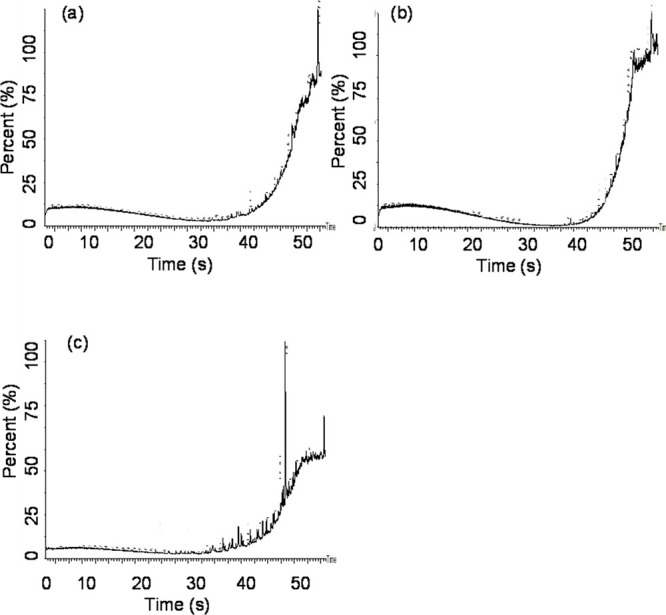
The effectiveness of the HNT-Ag-TiO2 loaded with 60:40 wt % binary mixture of Lecithin: Tween 80 in dispersing spills of crude oil was analyzed using the US EPA baffled flask test at different surfactant-to-oil ratios (SOR). From Figure 6, the highest dispersion effectiveness of 91.5% is recorded at an SOR of 22.50 mg/g. Once the HNT-Ag-TiO2-LT80 is applied to the oil–water mixture, the lecithin-Tween 80(LT) present is packed closely at the oil–water interface. The Lecithin possesses a reduced tendency to desorb strengthening the interfacial film and the Tween 80 with its large headgroup causes a repulsion between the oil droplets preventing coalescence.108 This confirms that the HNT-Ag-TiO2-LT80 is able to effectively disperse the crude oil. This result is not surprising since the emulsion stability test (see Supporting Information, Figure S2), optical microscopy images and droplet size analysis (see Supporting Information, Figure S3) and the surface tension measurement (see Supporting Information, Figure S4) all confirmed that HNT-Ag-TiO2-LT80 has the potential to disperse spilled crude oil. It should be noted that for a dispersant to be listed on the national product contingency schedule, it should be able to record at least 45% dispersion effectiveness. The synthesized HNT-Ag-TiO2-LT80 therefore has the potential to be used as an oil spill dispersant.
Figure 6.

Dispersion effectiveness of HNT-Ag-TiO2-LT80 at different SOR.
To further understand the photodegradation process, the GC-MS analysis was carried out on the crude oil, asphaltene fraction, and aromatic fraction of the crude oil. The GC-MS spectral results in comparison with library search were successful in enabling the identification of some compounds.
Comparing the GC-MS spectra of the undegraded crude oil to the degraded crude oil at different light irradiation period (Figure 7a–d), it was observed that a significant degradation takes place in the first 7 days (Figure 7c). The degradation further increased after 14 days (Figure 7d) of light irradiation. There was a substantial difference in the chromatograms and photodegraded compounds of the crude oil when Figure 7a–d are compared.
Figure 7.

GC-MS spectra of (a) 0 min/undegraded crude oil, (b) 30 min light irradiated crude oil, (c) 7 days light irradiated crude oil, and (d) 14 days light irradiated crude oil obtained with HNT-Ag-TiO2-LT80.
Again, comparing the degraded crude oil after 30 min (Figure 7b) and 7 days of light irradiation (Figure 7c), it can be seen that the compounds at the retention times of ca. 34 and 44 degraded after 7 days of light irradiation as indicated in Table S1b,c in the Supporting Information. Some of the pronounced peaks after 7 days of light irradiation were associated with the following compounds 1,4,4-trimethyl-2,6-diphenyl-1,4-dihydropyridine-3,5-dicarbonitrite, Betulin, a-Amyrin, and diisooctyl phthalate as indicated in Table S1c,d.
Degraded crude oil extract after 14 days of irradiation (Figure 7d) also showed degraded compounds formed and some compounds being maintained. Betulin is seen in both degraded crude oil samples after 7- and 14-days light irradiation at retention times 51.168 and 39.376 and % area of 3.72 and 2.13, respectively depicting a reduction in concentration as shown in Table S1d. a-Amyrin is seen after 7 days of light irradiation but disappeared after 14 days of light irradiation suggesting that a-Amyrin degraded after a relatively longer light irradiation. This result is consistent with the obtained UV–vis results in Figure S5c which showed significant photodegradation after 7 days of light irradiation.
The undegraded and photodegraded aromatic fraction of the crude oil was also analyzed with GC-MS and the results presented in Figure 8a–d. It was observed that a significant degradation takes place in the first 7 days and with the extent of degradation increasing as irradiation time increased. The chromatogram of the aromatic fraction irradiated for 30 min (Figure 8b) showed pronounced and distinct peaks and different compounds from that of the undegraded aromatic fraction (Figure 8a). Some of the compounds identified in undegraded aromatic fraction are Cholest-22-ene-21-ol, 3,5-dehydro-6-methoxy-, pivalate, Cyclononasiloxane, octadecamethyl, 2-Phenylethylamine, N,N-didecyl- as shown in Table S2a in the Supporting Information. However, after 30 min of UV light irradiation new compounds such as Lup-20(29)-en-3-one, Betulin, 1-Monolinoleoylglycerol trimethylsilyl ether, 5H-Cyclopropa[3,4]benz[1,2-e]azulen-5-one, 9,9a-bis(acetyloxy)-3-[(acetyloxy)methyl]-2-chloro-1. It should be stated that Heptasiloxane and hexadecamethyl were identified in both Figure 8a,b and also indicated in Table S2b in the Supporting Information.
Figure 8.

GC–MS spectra of (a) 0 min/undegraded aromatic fraction of crude oil (b) 30 min light irradiated aromatic fraction of crude oil, (c) 7 days light irradiated aromatic fraction of crude oil and (d) 14 days light irradiated aromatic fraction of crude oil obtained with HNT-Ag-TiO2-LT80.
Comparing the degraded aromatics after 30 min and 7 days of light irradiation in Figure 8b,c, respectively, it can be seen that degraded compounds appeared after 7 days of light irradiation. The degraded compounds identified in Figure 8c as indicated by Table S2c in the Supporting Information were diisooctyl phthalate, pregna-5,7-diene,3-(methoxymethoxy)-20-formyl, 5aH-3a,12-Methano-1H-cyclopropa[5′,6′]cyclodeca[1′,2′:1,5]cyclopenta[1,2-d][1,3]dioxol-13-one, 1a,2 and 1H-Cyclopropa[3,4]benz[1,2-e]azulene-5,7b,9,9a-tetrol,1a,1b,4,4a,5,7a,8,9-octahydro-3-(hydroxyme). Lup-20(29)-en-3-one was identified in both Figure 9b,c and also Table S2b,c in the Supporting Information. Betulin which was present after 30 min irradiation disappeared after 7 days of light irradiation as indicated in Table S2c in the Supporting Information.
Figure 9.
GC–MS spectra of (a) 0 min undegraded asphaltene fraction of crude oil (b) 30 min light irradiated asphaltene fraction of crude oil and (c) 7 days light irradiated asphaltene fraction of crude oil obtained with HNT-Ag-TiO2-LT80.
Aromatic fraction after 14 days of irradiation (Figure 8d) showed significant degradation accompanied by the formation of new compounds such as psi-Carotene, 1,1′,2,2′-tetrahydro-1,1′-dimethoxy, 9,12,15-octadecatrienoic acid and 2,3-bis[(trimethylsilyl)oxy] propyl ester. Again, heptasiloxane and hexadecamethyl are identified in Figure 8d as shown in Table S2d in the Supporting Information, implying that these compounds were not susceptible to photodegradation.
The degradation trend of the asphaltenes follows the same pattern as those of crude oil and aromatic fractions of crude oil are presented in Figure 9a–c. As the degradation progresses from 0 min to the seventh day irradiation time, significant degradation takes place with intermediates photodegradation products forming. The differences in the chromatograms and the compounds formed between the undegraded asphaltenes (Figure 9a) and the asphaltenes irradiated for 30 min (Figure 9b) were observed. After 7-day irradiation of the asphaltenes, Figure 9c and Table S3c in the Supporting Information show that Betulin, Heptasiloxane, hexadecamethyl, Lup-20(29)-en-3-one, à-Amyrin and trimethylsilyl ether found in Figure 9a,b and Table S3a,b in the Supporting Information disappeared, implying that the HNT-Ag-TiO2-LT80 was effective in photodegrading the asphaltene fraction of crude oil.
On the other hand, cyclononasiloxane, octadecamethyl, diisooctyl phthalate, and 1,4,4-trimethyl-2,6-diphenyl-1,4-dihydropyridine-3,5-dicarbonitrile photodegradation intermediate compounds were formed. Propanoic acid, 2-(3-acetoxy-4,4,14-trimethylandrost-8-en-17-yl), is seen in both undegraded and 7-day irradiated asphaltene fractions, as indicated in Table S3a,c in the Supporting Information, implying that these compounds could not be photodegraded. The results from the GC-MS analysis showed that HNT-Ag-TiO2-LT80 was effective in degrading crude oil and aromatic and asphaltene fractions of crude oil.
Conclusions
In this study, a photocatalyst-dispersant system of halloysite nanotube-silver nanoparticles with titanium dioxide, lecithin, and tween 80 (HNT-Ag-TiO2-LT80) has been developed.
The system was characterized with UV–vis analysis, Raman, TGA, CV, LSV, as well as SEM–EDX imaging, and FTIR spectroscopy was adopted to determine the presence of Ag in the photocatalyst.
The HNT-Ag-TiO2-LT80 exhibited an impressive 91.5% dispersion effectiveness in the baffled flask test, reducing surface tension and forming stable emulsions with smaller oil droplets.
UV-induced photodegradation of crude oil, aromatic, and asphaltene fractions was evident, revealing the composite’s potential for oil spill remediation.
Experimental Section
Materials
Dioctyl sulfosuccinate sodium salt (DOSS, 98%), Tween 80, dodecane, methanol, halloysite nanotubes, isopropyl alcohol, AgNO3, ethanol, and TiO2 nanoparticles were purchased from Sigma-Aldrich, UK. Instant Ocean salt was obtained from Instant Ocean (Blacksburg, VA). Deionized (DI) water, produced using the Elga water purification system (Medica DV25), possessing 18.2MΩ resistance, was employed in all the experimental engagements. Agbami crude oil with a density of 786.0 kg/m3, API gravity of 48.4 at 15 °C and density of 781.0 kg/m3 at 21.6 °C was obtained from Tema Oil Refinery (TOR), Tema, Ghana.
Preparation of HNT-Ag-TiO2 Composite (Ex-Situ Preparation)
The ex-situ preparation was in two parts. The first part (Part 1) was the synthesis of Ag-TiO2 via photodeposition, and the second part (Part 2). (Part 1): A solution named (A) was prepared by adding 0.5 wt % of Ag from AgNO3 to 50 mL of ethanol. Another solution (B) was formed by dispersing 1 g of TiO2 in 200 mL of deionized water. The solution that resulted was subjected to UV irradiation for 2 h. After it was centrifuged for 15 min and subjected to a 5 h drying at 105 °C. The as–prepared Ag-TiO2 was grounded with a mortar and pistol and sieved with a 75 μm sieve.
(Part 2): The as-prepared Ag-TiO2 was then loaded onto the HNT surface in this manner. A known amount (1 g) of halloysite nanotubes (HNTS) was added to 50 mL of ethanol and subjected to sonication for 60 min. The resulting mixture was labeled (C). Solution (C) was immediately added to the solution (D) made up of 1 g of Ag-TiO2 dispersed in 200 mL of deionized water and subjected to 1 h stirring in the dark. The resultant solution was then centrifuged for 15 min and subjected to a 5-h drying at 105 °C. The as-prepared HNT-Ag-TiO2 was grounded with a mortar and pistol and sieved with a 75 μm sieve.
Loading of HNT-Ag-TiO2 with Lecithin and Tween 80 (LT80)
A calculated amount (0.5 g) of HNT-Ag-TiO2 was weighed into a round-bottomed flask. A 20 mg/mL surfactant-ethanol solution was prepared using 20 wt % of the surfactant (lecithin–Tween 80 in 60 wt %: 40 wt %.). The HNT-Ag-TiO2-surfactant solution was subjected to continuous stirring for 30 and 1 min sonication. Vacuum suction was applied to load the binary surfactant mixture into the lumen of the HNTs. The vacuum suction was done in a repeated fashion for 15 min per session. This repeated session was done three times. The resulting HNT-Ag-TiO2 loaded surfactant was allowed to dry in order to evaporate the residual ethanol for the surfactant to crystallize in the HNT-Ag-TiO2. This composite made up of the photocatalyst and dispersant was labeled as HNT-Ag-TiO2-LT80
Characterization
X-ray Diffraction (XRD)
The crystal structure of Ag-TiO2 and HNTs-Ag-TiO2 particles were analyzed by employing the services of the X-ray powder diffraction (XRD) technique. The XRD characterization made use of a Bruker D8 X-ray diffractometer in theta–theta configuration with anode material Cu K-Alpha1 (wavelength of 1.54060 Å) and generator settings (40 mA, 45 kV). The XRD patterns of each of the randomly oriented powder specimens were captured in the 2θ range of 20°- 70° with a step size of 0.017°.
Raman Spectroscopy
Raman spectra of the TiO2 and the Ag-TiO2was acquired with uRaman/uSight version 11 with laser excitation at 531.89 nm.
Scanning Electron Microscopy–Energy-Dispersive X-ray Spectroscopy (SEM–EDX)
The services of a scanning electron microscopy-energy dispersive X-ray spectroscopy (SEM-EDX) on a FEI Tecnai G2 F30 twin transmission electron microscope was engaged for the analyses of the elemental composition and morphology of the TiO2, Ag-TiO2, HNT-Ag-TiO2 and the HNT-Ag-TiO2-LT80. It was operated at 300 kV.
Fourier Transform Infrared (FTIR) Spectroscopy
The FTIR spectra analysis of the TiO2, Ag-TiO2, HNT, HNT-Ag-TiO2 and HNT-Ag-TiO2-LT80 was done by engaging the Vertex 70 v (Bruker) FTIR spectrometer in transmission mode. This was carried out in a wavenumber range of 4000–400 cm–1 with 4 cm–1 resolution. The data analysis was performed using Opus software.
Thermalgravimetric Analysis (TGA)
The TA Instruments SDT 2960 Simultaneous DTA–TGA was engaged for TGA of the HNT, Ag-TiO2, HNT-Ag-TiO2 and HNT-Ag-TiO2-LT80. The analysis was carried out in an air environment using a 10 °C/min heating rate.
UV–Vis Spectroscopy
The UV–vis spectrometer was employed for the measurement of the absorbance and the diffuse reflectance of the HNT-Ag-TiO2, Ag-TiO2, and TiO2. The Tauc plot was then used to generate the band gap energies of the samples. In addition, UV–vis was also used to analyze the photodegraded oil samples.
Linear Sweep Voltammetry (LSV) and Cyclic Voltammetry (CV)
A cheapstat potentiostat connected to a desktop was engaged for the measurements of the linear sweep (LSV) and cyclic voltammetry (CV). CV measurement was used to evaluate the charge concentrations generated by the samples. The sensor of the potentiostat-galvanostat used is made up of a carbon electrode. A dispersed solution of 10 mg each of TiO2, Ag-TiO2, HNT-Ag-TiO2, and HNT-Ag-TiO2-LT80 was achieved by dissolving them in 200 mL of deionized water. The resultant solutions were irradiated with a UV light source for 2 h. After the irradiation, 5 μL of each of the aqueous samples was taken for the examination of their electrochemical performance by making use of Ag/AgCl as a reference electrode. The CV was achieved through a 160 mV/s constant scan rate with the potential window being −200 to 900 mV (vs Ag/AgCl). The LSV was set to 10 s at a sweep rate of 10 mV/s with a voltage range of −80 to 200 mV.
Baffled Flask Test
In the evaluation of the dispersion effectiveness of the HNT-Ag-TiO2-LT80, the baffled flask test was used; 120 mL of synthetic seawater was poured into a baffled flask. The addition of 100 μL of crude oil to the surface of the seawater in the baffled flask was carried out gently. Different amounts of the HNT-Ag-TiO2-LT80 corresponding to different surfactant-to-oil ratios (SOR) were added directly to the oil (crude oil, asphaltenes, or aromatic fractions) and seawater in the baffled flask. The baffled flask with the seawater, oil, and photocatalyst-dispersant composite was put on a VWR advanced digital shaker, Model 3500 and operated at 200 rpm for 10 min and afterward allowed to settle for 10 min. Thirty milliliters of the aqueous media of the dispersed oil was collected and the crude oil extraction was achieved with the aid of 20 mL of DCM. The crude oil in DCM was quantified using UV–vis set to an absorbance difference of 300–400 nm. The foregoing was carried out at room temperature.
Acknowledgments
This project was funded by the University of Ghana BANGA-Africa programme (Team research grant) with funding from the Carnegie Corporation of New York.
Data Availability Statement
The data sets generated during and/or analyzed during the current study are available from the corresponding author on reasonable request.
Supporting Information Available
The Supporting Information is available free of charge at https://pubs.acs.org/doi/10.1021/acsomega.3c05982.
Additional experimental details covering fractionation of the crude oil using column chromatography; preparation of the synthetic sea salt; optical microscopy of emulsions; measurement of surface tension; photocatalysis of the crude oil and the fractionated crude oil; GC–MS analysis; some results covering TGA analyses, emulsion stability analyses; optical microscopy images and histogram of o/w emulsion droplet sizes; surface tension; UV–vis analyses of the photodegraded products and the tables showing GC-MS identified compounds and their retention times for the photodegraded crude oil; and aromatics and asphaltenes (PDF)
Author Contributions
All authors contributed to the study conception and design. Material preparation, data collection and analysis were performed by E.N., B.A.-T., S.G., Y.K.A., and B.M. The first draft of the manuscript was written by E.N. and S.G. and all authors commented on previous versions of the manuscript. All authors read and approved the final manuscript.
The authors declare that this project was funded by the University of Ghana BANGA-Africa program with funding from the Carnegie Corporation of New York.
The authors declare no competing financial interest.
Notes
All authors have been personally and actively involved in substantial work leading to the paper and will take public responsibility for its content.
Notes
The paper is not currently being considered for publication elsewhere.
Supplementary Material
References
- Agyei-Tuffour B.; Gbogbo S.; Dodoo-Arhin D.; Damoah L. N. W.; Efavi J. K.; Yaya A.; et al. Photocatalytic degradation of fractionated crude oil: potential application in oil spill remediation. Cogent Eng. 2020, 7 (1), 1744944 10.1080/23311916.2020.1744944. [DOI] [Google Scholar]
- Nyankson E.; Rodene D.; Gupta R. B. Advancements in Crude Oil Spill Remediation Research After the Deepwater Horizon Oil Spill. Water Air Soil Pollut [Internet]. 2016, 227 (1), 29. 10.1007/s11270-015-2727-5. [DOI] [Google Scholar]
- Pi G.; Li Y.; Bao M.; Mao L.; Gong H.; Wang Z. Novel and Environmentally Friendly Oil Spill Dispersant Based on the Synergy of Biopolymer Xanthan Gum and Silica Nanoparticles. ACS Sustain Chem. Eng. 2016, 4 (6), 3095–102. 10.1021/acssuschemeng.6b00063. [DOI] [Google Scholar]
- Nyankson E.; DeCuir J. M.; Gupta B. R. Soybean Lecithin as a Dispersant for Crude Oil Spills. ACS Sustainable Chemistry & Engineering 2015, 3 (5), 920–31. 10.1021/acssuschemeng.5b00027. [DOI] [Google Scholar]
- Nyankson E.; DeCuir M. J.; Gupta R. B. Soybean Lecithin as a Dispersant for Crude Oil Spills. ACS Sustain Chem. Eng. 2015, 3 (5), 920–31. 10.1021/acssuschemeng.5b00027. [DOI] [Google Scholar]
- Nyankson E.; Olasehinde O.; John V. T.; Gupta R. B. Surfactant-Loaded Halloysite Clay Nanotube Dispersants for Crude Oil Spill Remediation. Ind. Eng. Chem. Res. [Internet]. 2015, 54 (38), 9328–41. 10.1021/acs.iecr.5b02032. [DOI] [Google Scholar]
- Doshi B.; Sillanpää M.; Kalliola S. A review of bio-based materials for oil spill treatment. Water Res. 2018, 135, 262–277. 10.1016/j.watres.2018.02.034. [DOI] [PubMed] [Google Scholar]
- Gupta S.; Tai N. H. Carbon materials as oil sorbents: A review on the synthesis and performance. J. Mater. Chem. A 2016, 4, 1550. 10.1039/C5TA08321D. [DOI] [Google Scholar]
- Jiang Z. R.; Ge J.; Zhou Y. X.; Wang Z. U.; Chen D.; Yu S. H.; et al. Coating sponge with a hydrophobic porous coordination polymer containing a low-energy CF3-decorated surface for continuous pumping recovery of an oil spill from water. NPG Asia Mater. 2016, 8 (3), e253 10.1038/am.2016.22. [DOI] [Google Scholar]
- Mills A.; Le Hunte S. An overview of semiconductor photocatalysis. J. Photochem. Photobiol. A Chem. 1997, 108 (1), 1–35. 10.1016/S1010-6030(97)00118-4. [DOI] [Google Scholar]
- Rueda-Marquez J. J.; Levchuk I.; Fernández Ibañez P.; Sillanpää M. A critical review on application of photocatalysis for toxicity reduction of real wastewaters. J. Clean Prod. 2020, 258, 120694 10.1016/j.jclepro.2020.120694. [DOI] [Google Scholar]
- Mathew S.; Ganguly P.; Kumaravel V.; Bartlett J.; Pillai S. C. Solar light-induced photocatalytic degradation of pharmaceuticals in wastewater treatment. Nano-Materials as Photocatalysts for Degradation of Environmental Pollutants: Challenges and Possibilities. 2020, 65–78. 10.1016/B978-0-12-818598-8.00004-3. [DOI] [Google Scholar]
- Su Y.; Chang Q.; Xue C.; Yang J.; Hu S. Solar-irradiated carbon dots as high-density hot spots in sponge for high-efficiency cleanup of viscous crude oil spill. J. Mater. Chem. A 2022, 10 (2), 585. 10.1039/D1TA08670G. [DOI] [Google Scholar]
- Ge J.; Shi L. A.; Wang Y. C.; Zhao H. Y.; Yao H. B.; Zhu Y. B.; et al. Joule-heated graphene-wrapped sponge enables fast clean-up of viscous crude-oil spill. Nat. Nanotechnol. 2017, 12 (5), 434. 10.1038/nnano.2017.33. [DOI] [PubMed] [Google Scholar]
- Chang J.; Shi Y.; Wu M.; Li R.; Shi L.; Jin Y.; et al. Solar-assisted fast cleanup of heavy oil spills using a photothermal sponge. J. Mater. Chem. A Mater. 2018, 6 (19), 9192–9. 10.1039/C8TA00779A. [DOI] [Google Scholar]
- Kujawinski E. B.; Kido Soule M. C.; Valentine D. L.; Boysen A. K.; Longnecker K.; Redmond M. C. Fate of dispersants associated with the Deepwater Horizon oil spill. Environ. Sci. Technol. 2011, 45 (4), 1298–306. 10.1021/es103838p. [DOI] [PubMed] [Google Scholar]
- Cai Q.; Zhu Z.; Chen B.; Lee K.; Nedwed T. J.; Greer C.; et al. A cross-comparison of biosurfactants as marine oil spill dispersants: Governing factors, synergetic effects and fates. J. Hazard Mater. 2021, 416, 126122 10.1016/j.jhazmat.2021.126122. [DOI] [PubMed] [Google Scholar]
- Bælum J.; Borglin S.; Chakraborty R.; Fortney J. L.; Lamendella R.; Mason O. U.; et al. Deep-sea bacteria enriched by oil and dispersant from the Deepwater Horizon spill. Environ. Microbiol. 2012, 14 (9), 2405–16. 10.1111/j.1462-2920.2012.02780.x. [DOI] [PubMed] [Google Scholar]
- Hazen T. C.; Dubinsky E. A.; DeSantis T. Z.; Andersen G. L.; Piceno Y. M.; Singh N.; et al. Deep-sea oil plume enriches indigenous oil-degrading bacteria. Science 2010, 330 (6001), 204–8. 10.1126/science.1195979. [DOI] [PubMed] [Google Scholar]
- Prince R. C.; McFarlin K. M.; Butler J. D.; Febbo E. J.; Wang F. C. Y.; Nedwed T. J. The primary biodegradation of dispersed crude oil in the sea. Chemosphere. 2013, 90 (2), 521–6. 10.1016/j.chemosphere.2012.08.020. [DOI] [PubMed] [Google Scholar]
- Prince R. C.; Amande T. J.; McGenity T. J.. Taxonomy, Genomics and Ecophysiology of Hydrocarbon-Degrading Microbes. In Handbook of Hydrocarbon and Lipid Microbiology; 2018. [Google Scholar]
- Chandrasekar S.; Sorial G. A.; Weaver J. W. Dispersant effectiveness on oil spills - impact of salinity. ICES Journal of Marine Science. 2006, 63 (8), 1418–30. 10.1016/j.icesjms.2006.04.019. [DOI] [Google Scholar]
- Nyankson E.; Demir M.; Gonen M.; Gupta R. B. Interfacially Active Hydroxylated Soybean Lecithin Dispersant for Crude Oil Spill Remediation. ACS Sustain Chem. Eng. 2016, 4 (4), 2056–67. 10.1021/acssuschemeng.5b01403. [DOI] [Google Scholar]
- Owoseni O., Nyankson E., Zhang Y., DAJ of C. Interfacial adsorption and surfactant release characteristics of magnetically functionalized halloysite nanotubes for responsive emulsions; Elsevier, 2016. (undefined). [DOI] [PubMed] [Google Scholar]
- Efavi J. K.; Nyankson E.; Yaya A.; Agyei-Tuffour B. Effect of Magnesium and Sodium Salts on the Interfacial Characteristics of Soybean Lecithin Dispersants. Ind. Eng. Chem. Res. 2017, 56 (44), 12608–20. 10.1021/acs.iecr.7b02862. [DOI] [Google Scholar]
- Yuewen D.; Adzigbli L. Assessing the Impact of Oil Spills on Marine Organisms. J. Oceanogr. Mar. Res. 2018, 6, 1. 10.4172/2572-3103.1000179. [DOI] [Google Scholar]
- Abdel-Shafy H. I.; Mansour M. S. M. A review on polycyclic aromatic hydrocarbons: source, environmental impact, effect on human health and remediation. Egyptian journal of petroleum. 2016, 25 (1), 107–23. 10.1016/j.ejpe.2015.03.011. [DOI] [Google Scholar]
- Fowzia A.; Fakhruddin A. N. M. A review on environmental contamination of petroleum hydrocarbons and its biodegradation. Int. J. Environ. Sci. Nat. Resour. 2018, 11 (3), 555811 10.19080/IJESNR.2018.11.555811. [DOI] [Google Scholar]
- Khan M. A. I.; Biswas B.; Smith E.; Naidu R.; Megharaj M. Toxicity assessment of fresh and weathered petroleum hydrocarbons in contaminated soil-a review. Chemosphere. 2018, 212, 755–67. 10.1016/j.chemosphere.2018.08.094. [DOI] [PubMed] [Google Scholar]
- Logeshwaran P.; Megharaj M.; Chadalavada S.; Bowman M.; Naidu R. Petroleum hydrocarbons (PH) in groundwater aquifers: An overview of environmental fate, toxicity, microbial degradation and risk-based remediation approaches. Environ. Technol. Innov. 2018, 10, 175–93. 10.1016/j.eti.2018.02.001. [DOI] [Google Scholar]
- Nyankson E.; Kumar R. V. Removal of water-soluble dyes and pharmaceutical wastes by combining the photocatalytic properties of Ag3PO4 with the adsorption properties of halloysite nanotubes. Mater. Today Adv. 2019, 4, 100025 10.1016/j.mtadv.2019.100025. [DOI] [Google Scholar]
- Som I.; Roy M.; Saha R. Advances in Nanomaterial-based Water Treatment Approaches for Photocatalytic Degradation of Water Pollutants. ChemCatChem. 2020, 12 (13), 3409–33. 10.1002/cctc.201902081. [DOI] [Google Scholar]
- Gopinath K. P.; Madhav N. V.; Krishnan A.; Malolan R.; Rangarajan G. Present applications of titanium dioxide for the photocatalytic removal of pollutants from water: A review. J. Environ. Manage. 2020, 270, 110906 10.1016/j.jenvman.2020.110906. [DOI] [PubMed] [Google Scholar]
- Nyankson E.; Yeboah N.; Jnr S. O.; Onaja S.; Mensah T.; Efavi J. K. The effect of synthesis route on the photocatalytic performance of Ag-TiO2 using rhodamine b dyes, pesticides, and pharmaceutical waste as model pollutants. Mater. Res. Express. 2022, 9 (9), 094001 10.1088/2053-1591/ac871f. [DOI] [Google Scholar]
- Saravanan A.; Kumar P. S.; Jeevanantham S.; Anubha M.; Jayashree S. Degradation of toxic agrochemicals and pharmaceutical pollutants: Effective and alternative approaches toward photocatalysis. Environ. Pollut. 2022, 298, 118844 10.1016/j.envpol.2022.118844. [DOI] [PubMed] [Google Scholar]
- Akhter P.; Nawaz S.; Shafiq I.; Nazir A.; Shafique S.; Jamil F.; et al. Efficient visible light assisted photocatalysis using ZnO/TiO2 nanocomposites. Molecular Catalysis. 2023, 535, 112896 10.1016/j.mcat.2022.112896. [DOI] [Google Scholar]
- Li M.; Yin J. J.; Wamer W. G.; Lo Y. M. Mechanistic characterization of titanium dioxide nanoparticle-induced toxicity using electron spin resonance. J. Food Drug Anal. 2014, 22 (1), 76–85. 10.1016/j.jfda.2014.01.006. [DOI] [PMC free article] [PubMed] [Google Scholar]
- Shang F. K.; Li Y. H.; Qi M. Y.; Tang Z. R.; Xu Y. J. Photocatalytic materials for sustainable chemistry via cooperative photoredox catalysis. Catal. Today. 2023, 410, 85–101. 10.1016/j.cattod.2022.04.007. [DOI] [Google Scholar]
- Thind S. S.; Paul M.; Hayden J. B.; Joshi A.; Goodlett D.; McIndoe J. S. A highly efficient photocatalytic system for environmental applications based on TiO 2 nanomaterials. Industrial Chemistry & Materials. 2023, 1 (3), 431–42. 10.1039/D3IM00053B. [DOI] [Google Scholar]
- Qi M. Y.; Conte M.; Anpo M.; Tang Z. R.; Xu Y. J. Cooperative coupling of oxidative organic synthesis and hydrogen production over semiconductor-based photocatalysts. Chem. Rev. 2021, 121 (21), 13051–85. 10.1021/acs.chemrev.1c00197. [DOI] [PubMed] [Google Scholar]
- Du Y.; Fu Y.; Gao X.; He W.; Zheng P. Halloysite-{TiO}2-Ag composites: Preparation, characterization and photodegradation. IOP Conf. Ser.: Mater. Sci. Eng. 2020, 729 (1), 012087 10.1088/1757-899X/729/1/012087. [DOI] [Google Scholar]
- Eddy D. R.; Permana M. D.; Sakti L. K.; Sheha G. A. N.; Hidayat S.; Solihudin; et al. Heterophase polymorph of TiO2 (Anatase, Rutile, Brookite, TiO2 (B)) for efficient photocatalyst: fabrication and activity. Nanomaterials 2023, 13 (4), 704. 10.3390/nano13040704. [DOI] [PMC free article] [PubMed] [Google Scholar]
- Chen D.; Cheng Y.; Zhou N.; Chen P.; Wang Y.; Li K.; et al. Photocatalytic degradation of organic pollutants using TiO2-based photocatalysts: A review. J. Clean Prod. 2020, 268, 121725 10.1016/j.jclepro.2020.121725. [DOI] [Google Scholar]
- Ishigaki T.; Nakada Y.; Tarutani N.; Uchikoshi T.; Tsujimoto Y.; Isobe M.; et al. Enhanced visible-light photocatalytic activity of anatase-rutile mixed-phase nano-size powder given by high-temperature heat treatment. R Soc. Open Sci. 2020, 7 (1), 191539 10.1098/rsos.191539. [DOI] [PMC free article] [PubMed] [Google Scholar]
- Isari A. A.; Payan A.; Fattahi M.; Jorfi S.; Kakavandi B. Photocatalytic degradation of rhodamine B and real textile wastewater using Fe-doped TiO2 anchored on reduced graphene oxide (Fe-TiO2/rGO): Characterization and feasibility, mechanism and pathway studies. Appl. Surf. Sci. 2018, 462, 549–64. 10.1016/j.apsusc.2018.08.133. [DOI] [Google Scholar]
- Gupta J., Hassan P. A., Barick K. C.. Defects in nanomaterials for visible light photocatalysis. In: Nanostructured Materials for Visible Light Photocatalysis; Elsevier: 2022; pp 319–350. [Google Scholar]
- Narkbuakaew T.; Sujaridworakun P. Role of Ag (0) deposited on TiO2 nanoparticles for superior photocatalytic performance induced by calcination. Opt Mater. (Amst). 2019, 98, 109407 10.1016/j.optmat.2019.109407. [DOI] [Google Scholar]
- Tseng H. C.; Chen Y. W. Facile synthesis of Ag/TiO2 by photoreduction method and its degradation activity of methylene blue under UV and visible light irradiation. Mod. Res. Catal. 2019, 9 (1), 1–19. 10.4236/mrc.2020.91001. [DOI] [Google Scholar]
- Liang H.; Jia Z.; Zhang H.; Wang X.; Wang J. Photocatalysis oxidation activity regulation of Ag/TiO2 composites evaluated by the selective oxidation of Rhodamine B. Appl. Surf. Sci. 2017, 422, 1–10. 10.1016/j.apsusc.2017.05.211. [DOI] [Google Scholar]
- Albiter E.; Valenzuela M. A.; Alfaro S.; Valverde-Aguilar G.; Martínez-Pallares F. M. Photocatalytic deposition of Ag nanoparticles on TiO2: Metal precursor effect on the structural and photoactivity properties. Journal of Saudi Chemical Society. 2015, 19 (5), 563–73. 10.1016/j.jscs.2015.05.009. [DOI] [Google Scholar]
- Wang X.; Wang Z.; Jiang X.; Tao J.; Gong Z.; Cheng Y.; et al. Silver-decorated TiO2 nanorod array films with enhanced photoelectrochemical and photocatalytic properties. J. Electrochem. Soc. 2016, 163 (10), H943. 10.1149/2.0551610jes. [DOI] [Google Scholar]
- Sterhov A. I., Loshkarev I. Y.. Determination of the proportion of natural light in solar radiation using the method of conversion of lighting units into energy. In Journal of Physics: Conference Series; IOP Publishing: 2019; p 012002. [Google Scholar]
- Odoi-Yorke F.; Akpahou R.; Opoku R.; Mensah L. D. Technical, financial, and emissions analyses of solar water heating systems for supplying sustainable energy for hotels in Ghana. Solar Compass. 2023, 7, 100051 10.1016/j.solcom.2023.100051. [DOI] [Google Scholar]
- Ortiz A. L.; Zaragoza M. M.; Gutiérrez J. S.; da Silva Paula M. M.; Collins-Martínez V. Silver oxidation state effect on the photocatalytic properties of Ag doped TiO2 for hydrogen production under visible light. Int. J. Hydrogen Energy 2015, 40 (48), 17308–17315. 10.1016/j.ijhydene.2015.09.058. [DOI] [Google Scholar]
- Stucchi M.; Bianchi C. L.; Argirusis C.; Pifferi V.; Neppolian B.; Cerrato G.; et al. Ultrasound assisted synthesis of Ag-decorated TiO2 active in visible light. Ultrason Sonochem. 2018, 40, 282–8. 10.1016/j.ultsonch.2017.07.016. [DOI] [PubMed] [Google Scholar]
- Zhang Y.; Fu F.; Li Y.; Zhang D.; Chen Y. One-step synthesis of Ag@ TiO2 nanoparticles for enhanced photocatalytic performance. Nanomaterials. 2018, 8 (12), 1032. 10.3390/nano8121032. [DOI] [PMC free article] [PubMed] [Google Scholar]
- Zhu Y.; Yang S.; Cai J.; Meng M.; Li X. A facile synthesis of AgxAu1– x/TiO2 photocatalysts with tunable surface plasmon resonance (SPR) frequency used for RhB photodegradation. Mater. Lett. 2015, 154, 163–6. 10.1016/j.matlet.2015.04.091. [DOI] [Google Scholar]
- Pascariu P.; Cojocaru C.; Airinei A.; Olaru N.; Rosca I.; Koudoumas E.; et al. Innovative ag–tio2 nanofibers with excellent photocatalytic and antibacterial actions. Catalysts. 2021, 11 (10), 1234. 10.3390/catal11101234. [DOI] [Google Scholar]
- Naik B.; Manoratne C. H.; Chandrashekhar A.; Iyer A.; Prasad V. S.; Ghosh N. N. Preparation of TiO2, Ag-doped TiO2 nanoparticle and TiO2–SBA-15 nanocomposites using simple aqueous solution-based chemical method and study of their photocatalytical activity. J. Exp Nanosci. 2013, 8 (4), 462–79. 10.1080/17458080.2011.597435. [DOI] [Google Scholar]
- Harikishore M.; Sandhyarani M.; Venkateswarlu K.; Nellaippan T. A.; Rameshbabu N. Effect of Ag doping on antibacterial and photocatalytic activity of nanocrystalline TiO2. Procedia materials science. 2014, 6, 557–66. 10.1016/j.mspro.2014.07.071. [DOI] [Google Scholar]
- Sarteep Z.; Ebrahimian Pirbazari A.; Aroon M. A. Silver doped TiO2 nanoparticles: preparation, characterization and efficient degradation of 2, 4-dichlorophenol under visible light. J. Water Environ. Nanotechnol. 2016, 1 (2), 135–144. 10.7508/jwent.2016.02.007. [DOI] [Google Scholar]
- Zhang D.; Chen J.; Xiang Q.; Li Y.; Liu M.; Liao Y. Transition-metal-ion (Fe, Co, Cr, Mn, Etc.) doping of TiO2 nanotubes: a general approach. Inorg. Chem. 2019, 58 (19), 12511–5. 10.1021/acs.inorgchem.9b01889. [DOI] [PubMed] [Google Scholar]
- Wenderich K.; Mul G. Methods, mechanism, and applications of photodeposition in photocatalysis: a review. Chem. Rev. 2016, 116 (23), 14587–619. 10.1021/acs.chemrev.6b00327. [DOI] [PubMed] [Google Scholar]
- Abbad S.; Guergouri K.; Gazaout S.; Djebabra S.; Zertal A.; Barille R.; et al. Effect of silver doping on the photocatalytic activity of TiO2 nanopowders synthesized by the sol-gel route. J. Environ. Chem. Eng. 2020, 8 (3), 103718 10.1016/j.jece.2020.103718. [DOI] [Google Scholar]
- Chakhtouna H.; Benzeid H.; Zari N.; El Qaiss A.; Bouhfid R. Recent progress on Ag/TiO2 photocatalysts: Photocatalytic and bactericidal behaviors. Environ. Sci. Pollut. Res. 2021, 28, 44638–44666. 10.1007/s11356-021-14996-y. [DOI] [PMC free article] [PubMed] [Google Scholar]
- Saleh T. A.; Gupta V. K. Photo-catalyzed degradation of hazardous dye methyl orange by use of a composite catalyst consisting of multi-walled carbon nanotubes and titanium dioxide. J. Colloid Interface Sci. 2012, 371 (1), 101–6. 10.1016/j.jcis.2011.12.038. [DOI] [PubMed] [Google Scholar]
- Saleh T. A.; Tuzen M.; Sarı A. Magnetic activated carbon loaded with tungsten oxide nanoparticles for aluminum removal from waters. J. Environ. Chem. Eng. 2017, 5 (3), 2853–60. 10.1016/j.jece.2017.05.038. [DOI] [Google Scholar]
- Alansi A. M.; Al-Qunaibit M.; Alade I. O.; Qahtan T. F.; Saleh T. A. Visible-light responsive BiOBr nanoparticles loaded on reduced graphene oxide for photocatalytic degradation of dye. J. Mol. Liq. 2018, 253, 297–304. 10.1016/j.molliq.2018.01.034. [DOI] [Google Scholar]
- Li C.; Yan L.; Li Y.; Zhang D.; Bao M.; Dong L. TiO2@palygorskite composite for the efficient remediation of oil spills via a dispersion-photodegradation synergy. Front. Environ. Sci. Eng. 2021, 15, 72. 10.1007/s11783-020-1365-3. [DOI] [Google Scholar]
- Zhou L.; Wang L.; Lei J.; Liu Y.; Zhang J. Fabrication of TiO2/Co-g-C3N4 heterojunction catalyst and its photocatalytic performance. Catal. Commun. 2017, 89, 125–8. 10.1016/j.catcom.2016.09.022. [DOI] [Google Scholar]
- Li J.; Liu K.; Xue J.; Xue G.; Sheng X.; Wang H.; et al. CQDs preluded carbon-incorporated 3D burger-like hybrid ZnO enhanced visible-light-driven photocatalytic activity and mechanism implication. J. Catal. 2019, 369, 450–61. 10.1016/j.jcat.2018.11.026. [DOI] [Google Scholar]
- Bellucci S.; Nyankson E.; Agyei-Tuffour B.; Adjasoo J.; Ebenezer A.; Dodoo-Arhin D.; Yaya A.; et al. Synthesis and Application of Fe-Doped TiO2-Halloysite Nanotubes Composite and Their Potential Application in Water Treatment. Adv. Mater. Sci. Eng. 2019, 2019, 4270310 10.1155/2019/4270310. [DOI] [Google Scholar]
- Dodoo-Arhin D.; Buabeng F. P.; Mwabora J. M.; Amaniampong P. N.; Agbe H.; Nyankson E.; et al. The effect of titanium dioxide synthesis technique and its photocatalytic degradation of organic dye pollutants. Heliyon. 2018, 4 (7), e00681 10.1016/j.heliyon.2018.e00681. [DOI] [PMC free article] [PubMed] [Google Scholar]
- Nyankson E.; Amedalor R.; Chandrabose G.; Coto M.; Krishnamurthy S.; Kumar R. V. Microwave-and formaldehyde-assisted synthesis of Ag–Ag3PO4 with enhanced photocatalytic activity for the degradation of rhodamine B dye and crude oil fractions. ACS Omega. 2020, 5 (23), 13641–55. 10.1021/acsomega.0c00670. [DOI] [PMC free article] [PubMed] [Google Scholar]
- Wen L.; Liu B.; Liu C.; Zhao X. Preparation, characterization and photocatalytic property of Ag-loaded TiO2 powders using photodeposition method. Journal of Wuhan University of Technology-Mater. Sci. Ed [Internet]. 2009, 24 (2), 258–63. 10.1007/s11595-009-2258-2. [DOI] [Google Scholar]
- Lee D. S.; Chen Y. W. Nano Ag/TiO2 catalyst prepared by chemical deposition and its photocatalytic activity. J. Taiwan Inst Chem. Eng. 2014, 45 (2), 705–12. 10.1016/j.jtice.2013.07.007. [DOI] [Google Scholar]
- Zambon R.; Franca M.; Zani V.; Pilot R.; Gross S.; Pedron D.; et al. Ag/TiO2 Nanocomposites for Nanothermometry in the Biological Environment. Eng. Proc. 2023, 35 (1), 16. 10.3390/IECB2023-14585. [DOI] [Google Scholar]
- Díaz-Uribe C.; Viloria J.; Cervantes L.; Vallejo W.; Navarro K.; Romero E.; et al. Photocatalytic activity of Ag-TiO2 composites deposited by photoreduction under UV irradiation. Int. J. Photoenergy 2018, 2018, 6080432 10.1155/2018/6080432. [DOI] [Google Scholar]
- Leong K. H.; Gan B. L.; Ibrahim S.; Saravanan P. Synthesis of surface plasmon resonance (SPR) triggered Ag/TiO2 photocatalyst for degradation of endocrine disturbing compounds. Appl. Surf. Sci. 2014, 319, 128–35. 10.1016/j.apsusc.2014.06.153. [DOI] [Google Scholar]
- Lim S. P.; Shahid M. M.; Rameshkumar P.; Huang N. M.; Che L. Amperometric detection of hydrogen peroxide and its density functional theory for adsorption on Ag/TiO 2 nanohybrid. Journal of Materials Science: Materials in Electronics. 2020, 31, 6017–26. 10.1007/s10854-020-03153-9. [DOI] [Google Scholar]
- Durango-Giraldo G.; Cardona A.; Zapata J. F.; Santa J. F.; Buitrago-Sierra R. Titanium dioxide modified with silver by two methods for bactericidal applications. Heliyon 2019, 5 (5), e01608 10.1016/j.heliyon.2019.e01608. [DOI] [PMC free article] [PubMed] [Google Scholar]
- Wang Y.; Huang Y.; Ho W.; Zhang L.; Zou Z.; Lee S. Biomolecule-controlled hydrothermal synthesis of C–N–S-tridoped TiO2 nanocrystalline photocatalysts for NO removal under simulated solar light irradiation. J. Hazard Mater. 2009, 169 (1–3), 77–87. 10.1016/j.jhazmat.2009.03.071. [DOI] [PubMed] [Google Scholar]
- Alsharaeh E. H.; Bora T.; Soliman A.; Ahmed F.; Bharath G.; Ghoniem M. G.; et al. Sol-gel-assisted microwave-derived synthesis of anatase Ag/TiO2/GO nanohybrids toward efficient visible light phenol degradation. Catalysts. 2017, 7 (5), 133. 10.3390/catal7050133. [DOI] [Google Scholar]
- Serrano J. G.; Hernandez E. G.; Fernandez M. O.; Pal U. Effect of Ag Doping on the Crystallization and Phase Transition of TiO2 NPs. Curr. Appl. Phys. 2009, 9, 1097–1105. 10.1016/j.cap.2008.12.008. [DOI] [Google Scholar]
- Choi S. S.; Chu B.; Lee S. G.; Lee S. W.; Im S. S.; Kim S. H.; et al. Titania-doped silica fibers prepared by electrospinning and sol-gel process. J. Solgel Sci. Technol. 2004, 30, 215–21. 10.1023/B:JSST.0000039530.09380.bc. [DOI] [Google Scholar]
- Mihaly Cozmuta A.; Peter A.; Mihaly Cozmuta L.; Nicula C.; Crisan L.; Baia L.; et al. Active packaging system based on Ag/TiO2 nanocomposite used for extending the shelf life of bread. Chemical and microbiological investigations. Packaging Technology and Science. 2015, 28 (4), 271–84. 10.1002/pts.2103. [DOI] [Google Scholar]
- Nyankson E.; Olasehinde O.; John V. T.; Gupta R. B. Surfactant-Loaded Halloysite Clay Nanotube Dispersants for Crude Oil Spill Remediation. Ind. Eng. Chem. Res. 2015, 54 (38), 9328–41. 10.1021/acs.iecr.5b02032. [DOI] [Google Scholar]
- Tai L. N.; Long P. D.; Le H.; Thi N.; Van Hong L.; Khuyen B. X.; et al. Photocatalytic and water-splitting properties of TiO2 and Ag–TiO2 films in the visible light region. AIP Adv. 2021, 11 (7), 075118 10.1063/5.0058116. [DOI] [Google Scholar]
- Vinu R.; Madras G. Photocatalytic activity of Ag-substituted and impregnated nano-TiO2. Appl. Catal. A Gen. 2009, 366 (1), 130–40. 10.1016/j.apcata.2009.06.048. [DOI] [Google Scholar]
- Sukitpong J, Chiarakorn S. Degradation of acetaldehyde by Ag/TiO2 photocatalyst coated on polyester air filter. In: IOP Conference Series: Earth and Environmental Science; IOP Publishing: 2019; p 012020. [Google Scholar]
- Jubu P. R.; Yam F. K.; Igba V. M.; Beh K. P. Tauc-plot scale and extrapolation effect on bandgap estimation from UV–vis–NIR data–a case study of β-Ga2O3. J. Solid State Chem. 2020, 290, 121576 10.1016/j.jssc.2020.121576. [DOI] [Google Scholar]
- Tauc J.; Grigorovici R.; Vancu A. Optical properties and electronic structure of amorphous germanium. physica status solidi (b). 1966, 15 (2), 627–37. 10.1002/pssb.19660150224. [DOI] [Google Scholar]
- Sakthivel S.; Hidalgo M. C.; Bahnemann D. W.; Geissen S. U.; Murugesan V.; Vogelpohl A. A fine route to tune the photocatalytic activity of TiO2. Appl. Catal., B 2006, 63 (1–2), 31–40. 10.1016/j.apcatb.2005.08.011. [DOI] [Google Scholar]
- Makuła P.; Pacia M.; Macyk W. How to correctly determine the band gap energy of modified semiconductor photocatalysts based on UV–Vis spectra. J. Phys. Chem. Lett. 2018, 9, 6814–6817. 10.1021/acs.jpclett.8b02892. [DOI] [PubMed] [Google Scholar]
- Stucchi M.; Cerrato G.; Bianchi C. L. Ultrasound to improve both synthesis and pollutants degradation based on metal nanoparticles supported on TiO2. Ultrason Sonochem. 2019, 51, 462–8. 10.1016/j.ultsonch.2018.07.011. [DOI] [PubMed] [Google Scholar]
- Kubacka A.; Muñoz-Batista M. J.; Ferrer M.; Fernández-García M. UV and visible light optimization of anatase TiO2 antimicrobial properties: Surface deposition of metal and oxide (Cu, Zn, Ag) species. Appl. Catal., B 2013, 140, 680–90. 10.1016/j.apcatb.2013.04.077. [DOI] [Google Scholar]
- Hernández J. V.; Coste S.; Murillo A. G.; Romo F. C.; Kassiba A. Effects of metal doping (Cu, Ag, Eu) on the electronic and optical behavior of nanostructured TiO2. J. Alloys Compd. 2017, 710, 355–363. 10.1016/j.jallcom.2017.03.275. [DOI] [Google Scholar]
- An Y.; Yang L.; Hou J.; Liu Z.; Peng B. Synthesis and characterization of carbon nanotubes-treated Ag@ TiO2 core–shell nanocomposites with highly enhanced photocatalytic performance. Opt Mater. (Amst). 2014, 36 (8), 1390–5. 10.1016/j.optmat.2014.03.038. [DOI] [Google Scholar]
- Khan M. R.; Chuan T. W.; Yousuf A.; Chowdhury M. N. K.; Cheng C. K. Schottky barrier and surface plasmonic resonance phenomena towards the photocatalytic reaction: study of their mechanisms to enhance photocatalytic activity. Catal. Sci. Technol. 2015, 5 (5), 2522–31. 10.1039/C4CY01545B. [DOI] [Google Scholar]
- Elgrishi N.; Rountree K. J.; McCarthy B. D.; Rountree E. S.; Eisenhart T. T.; Dempsey J. L. A practical beginner’s guide to cyclic voltammetry. J. Chem. Educ. 2018, 95 (2), 197–206. 10.1021/acs.jchemed.7b00361. [DOI] [Google Scholar]
- Pascariu P.; Homocianu M.; Vacareanu L.; Asandulesa M. Multi-Functional Materials Based on Cu-Doped TiO2 Ceramic Fibers with Enhanced Pseudocapacitive Performances and Their Dielectric Characteristics. Polymers (Basel). 2022, 14 (21), 4739. 10.3390/polym14214739. [DOI] [PMC free article] [PubMed] [Google Scholar]
- Kumar M. R. A.; Abebe B.; Nagaswarupa H. P.; Murthy H. C. A.; Ravikumar C. R.; Sabir F. K. Enhanced photocatalytic and electrochemical performance of TiO2-Fe2O3 nanocomposite: Its applications in dye decolorization and as supercapacitors. Sci. Rep. 2020, 10 (1), 1249. 10.1038/s41598-020-58110-7. [DOI] [PMC free article] [PubMed] [Google Scholar]
- Moriyama A.; Yamada I.; Takahashi J.; Igarashi H. Oxidative stress caused by TiO2 nanoparticles under UV irradiation is due to UV irradiation not through nanoparticles. Chem. Biol. Interact. 2018, 294, 144–150. 10.1016/j.cbi.2018.08.017. [DOI] [PubMed] [Google Scholar]
- Wang Y.; Zhitomirsky I. Electrophoretic Deposition of Manganese Dioxide–Multiwalled Carbon Nanotube Composites for Electrochemical Supercapacitors. Langmuir. 2009, 25 (17), 9684–9. 10.1021/la900937e. [DOI] [PubMed] [Google Scholar]
- Yan J.; Wei T.; Shao B.; Ma F.; Fan Z.; Zhang M.; et al. Electrochemical properties of graphene nanosheet/carbon black composites as electrodes for supercapacitors. Carbon N Y. 2010, 48 (6), 1731–7. 10.1016/j.carbon.2010.01.014. [DOI] [Google Scholar]
- Chaudhary D.; Singh S.; Vankar V. D.; Khare N. A ternary Ag/TiO2/CNT photoanode for efficient photoelectrochemical water splitting under visible light irradiation. Int. J. Hydrogen Energy. 2017, 42 (12), 7826–35. 10.1016/j.ijhydene.2016.12.036. [DOI] [Google Scholar]
- Luo J.; Ma Y.; Wang H.; Chen J. Preparation of polypyrrole sensitized TiO2 nanotube arrays hybrids for efficient photoelectrochemical water splitting. Electrochim. Acta 2015, 167, 119–25. 10.1016/j.electacta.2015.03.097. [DOI] [Google Scholar]
- Athas C. J.; Jun K.; McCafferty C.; Owoseni O.; John T. V.; Raghavan R. S. An Effective Dispersant for Oil Spills Based on Food-Grade Amphiphiles. Langmuir. 2014, 30 (31), 9285–94. 10.1021/la502312n. [DOI] [PubMed] [Google Scholar]
Associated Data
This section collects any data citations, data availability statements, or supplementary materials included in this article.
Supplementary Materials
Data Availability Statement
The data sets generated during and/or analyzed during the current study are available from the corresponding author on reasonable request.