

Abstract
In recent years, hafnium oxide (HfO2) has gained increasing interest because of its high dielectric constant, excellent thermal stability, and high band gap. Although HfO2 bulk and film materials have been prepared and well-studied, HfO2 fibers, especially hollow fibers, have been less investigated. In this study, we present a facile preparation method for HfO2 hollow fibers through a unique integration of the sol–gel process and electrospinning technique. Initially, polystyrene (PS) fibers are fabricated by using electrospinning, followed by dipping in a HfO2 precursor solution, resulting in HfO2-coated PS fibers. Subsequent thermal treatment at 800 °C ensures the selective pyrolysis of the PS fibers and complete condensation of the HfO2 precursors, forming HfO2 hollow fibers. Scanning electron microscopy (SEM) characterizations reveal HfO2 hollow fibers with rough surfaces and diminished diameters, a transformation attributed to the removal of the PS fibers and the condensation of the HfO2 precursors. Our study also delves into the influence of precursor solution molar ratios, showcasing the ability to achieve smaller HfO2 fiber diameters with reduced precursor quantities. Validation of the material composition is achieved through thermogravimetric analysis (TGA) and energy-dispersive spectroscopy (EDS) mapping. Additionally, X-ray diffraction (XRD) analysis provides insights into the crystallinity of the HfO2 hollow fibers, highlighting a higher crystallinity in fibers annealed at 800 °C compared with those treated at 400 °C. Notably, the HfO2 hollow fibers demonstrate a water contact angle (WCA) of 38.70 ± 5.24°, underscoring the transformation from hydrophobic to hydrophilic properties after the removal of the PS fibers. Looking forward, this work paves the way for extensive research on the surface properties and potential applications of HfO2 hollow fibers in areas such as filtration, energy storage, and memory devices.
Introduction
Hafnium oxide (HfO2) has been widely used in metal–oxide–semiconductor devices,1 optoelectronics,2 and microelectronics3 because of its high-k dielectric constant,4 excellent mechanical property,5 thermal stability,6 and wide band gap energy.7 The HfO2 materials with special morphologies have been applied to different fields. For example, Qiu et al. have applied the coating method by nano-HfO2 fibers on a W–Re alloy, showing a thermal shock resistance with high melting point (above 3000 K).8 Besides, Kahro et al. have reported a HfO2 film grown by atomic layer deposition (ALD), revealing the applications of resistive switching media.9 These applications are based on the physicochemical properties of HfO2 materials and the high surface areas of the nanostructures.
Other than HfO2 bulk materials, HfO2 materials with special morphologies have been prepared using various approaches, such as atomic layer deposition,10−12 electrochemical anodization,13−15 thermal oxidation,6,16,17 and the sol–gel process.18−20 For example, atomic layer deposition has been used to generate ultrathin HfO2 layers, which can further be used in Li–S batteries,21 gas sensing,22 and high-performance field emitters.2 Besides, Su et al. used electrospinning of sol–gel solutions to generate HfO2 nanobelts.23 Similarly, Xu et al. used the electrospinning method to produce HfO2 nanofibers.24 Moreover, Berger et al. used an electrochemical process to produce HfO2 nanotubes from pure Hf foils.25 Despite these works, it is still challenging to develop economical ways to fabricate HfO2 materials with special morphologies, especially HfO2 hollow fibers, considering their high specific surface areas.
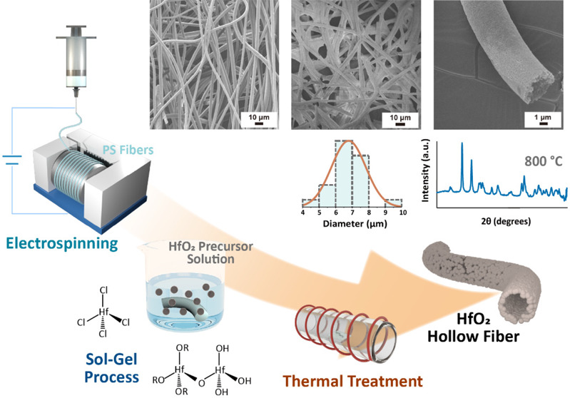
To this end, in this work, we present a facile and versatile strategy to prepare HfO2 hollow fibers using a combination of sol–gel and electrospinning methods. First, polystyrene (PS) fibers are formed by the electrospinning technique. Subsequently, the electrospun PS fibers are coated with a HfO2 precursor solution, forming the HfO2-coated PS fibers after drying. By thermal treatment at a high temperature (800 °C), the HfO2 precursors condense and the PS fibers are selectively pyrolyzed, resulting in the formation of HfO2 hollow fibers. From the scanning electron microscopy (SEM) characterizations, the HfO2 hollow fibers show relatively rougher surfaces and reduced diameters, caused by the condensation of the HfO2 precursors and the disappearance of the PS fibers. We also investigate the effect of the molar ratios of the precursor solutions, presenting that HfO2 fibers with smaller diameters can be obtained using fewer amounts of the precursors. We also confirm the compositions of the prepared materials with thermogravimetric analysis (TGA) and energy-dispersive spectroscopy (EDS) mapping. Moreover, the X-ray diffraction (XRD) analysis studies display that the crystallinities of the HfO2 hollow fibers annealed at 800 °C are higher than those annealed at 400 °C. Furthermore, a water contact angle (WCA) of 38.70 ± 5.24° is obtained for the HfO2 hollow fibers, caused by the nature of the hydrophilic HfO2 and the removal of the hydrophobic PS fibers. Compared with other studies,24 our works demonstrate a versatile strategy to fabricate not only HfO2 fibers but also HfO2 hollow fibers. In addition, the combination of our polymer and sol–gel method requires lower processing temperature (400 or 800 °C) to obtain crystalline HfO2 materials. We believe that HfO2 hollow fibers may have great application potentials in various fields, such as filtration, energy storage, and memory devices.
Results and Discussion
To prepare metal oxide nanomaterials at relatively lower temperatures, the sol–gel method is an ideal alternative to simplifying the process. Figure 1a,b shows the sol–gel process and reaction schemes of HfO2 formation. Hafnium(IV) chloride (HfCl4) is first dissolved in an organic solvent (propylene glycol methyl ether, PGME) to form HfO2 precursors. The hafnium atom in the complex is highly electrophilic, which tends to be attacked by oxygen and forms a hafnium alkoxide. Later, the hafnium alkoxide complex in the aqueous solution undergoes hydrolysis by replacing the alkyl group with the hydroxy group of water molecules (Figure 1a). Subsequently, the alkylated and hydrolyzed hafnium goes through polycondensation to produce a thick hafnium complex gel (Figure 1b). To understand the impact of reaction times and solvents during the gelation process, we also conducted dynamic light scattering (DLS) experiments on the sol–gel time, as shown in Figure S1.
Figure 1.

(a, b) Sol–gel process and reaction schemes of HfO2 formation. (c) Schematic illustrations depicting electrospinning, HfO2 coating, and pyrolysis to produce the HfO2 hollow fibers.
Figure 1c shows the schematic illustrations depicting electrospinning, HfO2 coating, and pyrolysis to produce HfO2 hollow fibers. At first, a PS solution (20% w/w) in DMF is electrospun into PS fibers. Subsequently, the electrospun PS fibers are coated with a HfO2 precursor solution using the dip-coating method to form the HfO2-coated PS fibers. For the annealing temperature, we chose 800 °C according to previous studies for obtaining HfO2 materials with crystalline structures.18,26 After the thermal treatment at a high temperature (800 °C), the PS fibers are selectively pyrolyzed, and the HfO2 precursors condense, resulting in the formation of HfO2 hollow fibers. The sol–gel process is also conducted on silicon wafers to observe the relationships between the material properties and reactions. Upon the thermal treatments, the thicknesses of the HfO2 layers are reduced with the increases of temperature, revealing the evaporation of PGME solvents and the condensation of the HfO2 layers, as shown in Figure S2.
The morphologies of the PS fibers, HfO2 coated fibers, and HfO2 hollow fibers are examined by scanning electron microscopy (SEM), as shown in Figure 2. The SEM images of the electrospun PS fibers are shown in Figure 2a,b. The surfaces of the PS fibers are relatively smooth, with an average diameter of 4.2 μm, as displayed in Figure 2c. The thermogravimetric analysis (TGA) of the PS fibers demonstrates that the PS polymers remain stable at temperatures below ∼300 °C, as shown in Figure 2d. The 5 wt % weight loss of the PS polymers occurs at ∼350 °C, and complete degradation appears at ∼430 °C. The SEM images of the HfO2 precursor-coated PS fibers are shown in Figure 2e,f. The diameters of the fibers increased to 7.8 μm, as displayed in Figure 2g. The TGA curve of the HfO2 precursor-coated PS fibers demonstrates that the weights decrease significantly at ∼400 °C, mostly attributed to the loss of PS fibers. It should be noted that ∼3.5 wt % mass is still left even when the temperature is increased to 600 °C, indicating the presence of HfO2 even at high temperatures.
Figure 2.

SEM images of PS fibers (a, b), HfO2 coated fibers (e, f), and HfO2 hollow fibers (i, j) with their corresponding fiber diameter distributions (c, g, k) and TGA graphs (d, h, l).
For the HfO2 hollow fibers, relatively rougher surfaces are observed in the SEM images (Figure 2i,j). The opening of a HfO2 hollow fiber is indicated by a red arrow. The diameters of the hollow fibers decrease to 4.4 μm compared with those of the HfO2 precursor-coated PS fibers, as displayed in Figure 2k. The reduction of the fiber diameter can be attributed to the disappearance of the PS fibers as well as the condensation of the HfO2 precursors. The TGA measurement of the HfO2 hollow fibers demonstrates that no weight loss is observed even when the temperature is increased to 600 °C, confirming the thermal stability of the hollow HfO2 fibers.
We also investigated the effect of the PGME molar ratios. Figure 3 shows the SEM images of the HfO2 hollow fibers prepared with different HfCl4 to PGME molar ratios (1:100, 1:200, 1:300, and 1:400). It can be seen that the HfO2 hollow fibers can all be successfully fabricated. The thicknesses of HfO2 layers on silicon wafers are also observed via a profilometer, as shown in Figure S3. Because the total amounts of HfCl4 to PGME are fixed, the more amounts of PGME as the solvents are added in the sol–gel precursor, the lower the HfO2 thicknesses are observed. Moreover, as the amount of PGME increases, more collapsed and ribbon-like structure can be observed. Besides, for the molar ratios of 1:100, 1:200, 1:300, and 1:400, the average diameters of the HfO2 hollow fibers are recorded as 4.43, 4.35, 4.11, and 3.40 μm, respectively. The smaller diameters are caused by the fewer amounts of the precursors. For further characterizations, the molar ratio of HfCl4:PGME = 1:100 is mainly chosen to prepare HfO2 hollow fibers because of their relatively better surface morphologies and larger diameters. Previous works have reported the importance of the solvent in determining gelation reaction rates, indicating the viscosity and hydration effects in the precursor solutions.27 The solvation effect in different sol–gel precursor solvents has been tested, as displayed in Figure S4.
Figure 3.

SEM images of HfO2 hollow fibers with different molar ratios of HfCl4 to PGME: (a, e) 1:100, (b, f) 1:200, (c, g) 1:300, and (d, h) 1:400. (i–l) Corresponding diameter distributions of the fibers.
The HfO2 hollow fibers are also characterized by energy-dispersive spectroscopy (EDS) mapping, X-ray diffraction (XRD), and water contact angle (WCA) measurements. Figure 4a–e shows the SEM image of an HfO2 hollow fiber with corresponding EDS images. Figure 4b displays the signal of the Si element, which is mainly from the silicon wafer under the fibers, while the HfO2 hollow fiber does not show the Si signal. Figures 4c and 4d show the signals of the Hf and O elements, respectively, that appear on the locations of the fibers, demonstrating the formation of HfO2. Figure 4e is the mapping image of the C element; the C signals that appeared indicate the presence of the residual carbon after the high-temperature pyrolysis of the PS fibers. The X-ray photoelectron spectroscopy (XPS) experiments are also conducted to measure the surface compositions of the fibers, as shown in Figure S5. After pyrolysis of the PS fibers, the signals of C 1s attributed to PS decrease; in contrast, the signals of O 1s, Hf 4p, Hf 4d, and Hf 4f increase, indicating the reduction of the polymer and the formation of HfO2.
Figure 4.

(a) SEM image of a HfO2 hollow fiber with corresponding EDS images: (b) Si, (c) Hf, (d) O, and (e) C. (f) XRD spectra of HfO2 hollow fibers after annealing at 400 (black) and 800 °C (blue). (g) Water contact angles (WCA) of PS fibers, HfO2 coated PS fibers, HfO2 hollow fibers, and HfO2 films coated on silicon substrates.
Furthermore, HfO2 hollow fibers are investigated by X-ray diffraction (XRD) measurements. Figure 4f shows the XRD curves of HfO2 hollow fibers using a molar ratio of [HfCl4]:[PGME] = 1:100 and annealing at 400 °C (black) and 800 °C (blue). The peaks at ∼29° and ∼32° can be attributed to the (100) and (111) planes of monoclinic HfO2. For the HfO2 hollow fibers annealed at 800 °C, however, more crystalline peaks with higher intensities can be observed than those annealed at 400 °C. The results show that annealing at higher temperatures can improve the crystalline structures of the HfO2.
In addition, the surface properties of the samples are also evaluated. Figure 4g shows the water contact angle (WCA) of PS fibers, HfO2 coated PS fibers, HfO2 hollow fibers, and HfO2 films coated on silicon substrate at room temperature with a water drop size of 10 μL. For PS fibers, the WCA is 134.8 ± 6.76°, which is reasonable considering the hydrophobic nature and fiber structures.28,29 Interestingly, the WCA of the HfO2 coated PS fibers is still high (133.1 ± 1.08°), probably due to the partial coverage of the HfO2 coating on the PS fibers. As the lotus effect, these structures are likely to be in the Cassie–Baxter state, suggesting surface-roughness-enhanced hydrophobicity. After thermal treatments, the pyrolysis of the PS fibers is conducted, maintaining the hollow HfO2 fiber structures. The HfO2 hollow fibers exhibit a much lower WCA (38.70 ± 5.24°), caused by the removal of the hydrophobic PS fibers and the nature of the hydrophilic HfO2. The WCAs of the HfO2 hollow fibers are lower than those of HfO2 films coated on silicon substrates As shown in Figures 2i,j and 3a–h, the HfO2 layers of the hollow fibers have a granular texture with some pores (∼10 nm) on the surfaces. Those structures could cause the hollow HfO2 fibers to become porous and water-absorbing materials, related to the Wenzel state. Compared with the pure HfO2 films with hydrophilic surfaces caused by OH groups, the hollow HfO2 fibers with high porosity present a lower WCA because of water absorption by the rough surfaces of the HfO2 hollow fibers.
Conclusions
In this work, we successfully synthesize HfO2 hollow fibers using a combination of sol–gel and electrospinning methods. After the formation of the PS fibers using electrospinning, HfO2 precursor solution are coated on the electrospun PS fibers, forming the HfO2-coated PS fibers. By thermal treatment at a high temperature (800 °C), the PS fibers are selectively pyrolyzed, and the HfO2 precursors condense, resulting in the formation of HfO2 hollow fibers. The morphologies of the prepared materials are examined by SEM; HfO2 hollow fibers with relatively rougher surfaces and reduced diameters are observed, attributed to the disappearance of the PS fibers and the condensation of the HfO2 precursors. The effect of the molar ratios of the precursor solutions is also investigated, demonstrating that HfO2 fibers with smaller diameters can be obtained using the fewer amounts of the precursors. TGA and EDS mapping are also applied to confirm the compositions of the prepared materials.
Furthermore, the XRD results indicate that the crystallinities of the HfO2 hollow fibers annealed at 800 °C are higher than those annealed at 400 °C. In addition, the HfO2 hollow fibers exhibit a WCA of 38.70 ± 5.24°, caused by the removal of the hydrophobic PS fibers and the nature of the hydrophilic HfO2. In the future, we will further study the surface properties and applications of the HfO2 hollow fibers such as filtration, energy storage, and memory devices.
Experimental Section
Materials
Polystyrene (PS) (Mw: 192000 g/mol) was purchased from Sigma-Aldrich. Nitric acid (HNO3) (60%) was obtained from J. T. Baker. Dimethylformamide (DMF) and hafnium(IV) chloride (HfCl4) (98%) were purchased from Echo Chemical. 1-Propanol (99%), ethanol (99%), and 1-methoxy-2-propanol (PGME, 99.5%) were purchased from Uni-Onward. The chemicals were used without further purification.
Preparation of Polystyrene (PS) Fibers through Electrospinning
The electrospinning process was based on our previous work with some modifications.29,30 A PS (20 wt %) solution in DMF was prepared in a 20 mL glass vial. This solution was added to a 5 mL syringe, which was further attached to a capillary nozzle having an inner diameter of 0.41 mm. The syringe containing the polymer solution was connected to the pump. A 10 kV voltage was provided by using a power supply (SIMCO). A grounded rotating aluminum drum (rotating speed: 800 rpm) was used to collect the electrospun fibers. The working distance between the nozzle and the collector was kept constant at 15 cm. The spinning duration was ∼3 h for forming the pieces of fabrics. After the electrospinning process, PS fibers were dried at room temperature and stored for analysis and further processing.
Preparation of Hafnium Oxide Sol–Gel Precursors
To prepare hafnium oxide (HfO2) sol–gel precursors, 1 mol of hafnium tetrachloride (HfCl4) was dissolved in a 20 mL glass vial containing propylene glycol methyl ether (PGME) (100 mol) at room temperature with constant stirring. HNO3 acid (4 mol) was then added dropwise to the solution and stirred until a clear solution mixture was observed. The solution was further heated at 100 °C for 2 h using a hot plate (Corning PC-420D) with a stirring speed of 100 rpm. After 2 h, the prepared gel solution was stored at 4 °C for further experiment. PGME with other ratios (200, 300, and 400 mol) were also prepared using the same protocol to study the solvent concentration effect on the fibers.
Preparation of Hollow Hafnium Oxide Fibers
The PS fiber mat (1 cm × 1 cm) was dipped into a hafnium oxide sol–gel solution for 1 min at room temperature. After coating, the fibers were washed using DI water three times (1 min for each time) to ensure the removal of the nonbounded gel solution. The washed fibers were dried by using a vacuum pump. Finally, the dried fibers were kept in a heating furnace at 800 °C using a heating rate of 1 °C/min to degrade the PS polymer from the fibers, producing HfO2 hollow fibers.
Characterization
A scanning electron microscope (SEM, JEOL JSM-7401F) and energy-dispersive X-ray spectroscopy (EDS, Hitachi SU-8010) were used to measure the fiber morphologies and the elementals present in the fiber interior by using an acceleration voltage of 5 kV. A thermogravimetric analysis (TGA) was used to determine the thermal stability and degradation of the PS fibers. The crystallinities of the HfO2 fibers were observed using X-ray diffraction (XRD) with beamline 13A1 of the National Synchrotron Radiation Research Center (NSRRC) located at Hsinchu, Taiwan. The wettabilities of the fiber surfaces were determined using a digidrop contact angle meter (goniometer, FTA 125) with deionized water droplets with sizes of 10 μL. For the annealing process, a heating furnace (tube furnace, Linberg/Blue, HTF55347C) was used with a heating rate of 1 °C/min.
Acknowledgments
This work was supported by the 2030 Cross-Generation Young Scholars Program of the National Science and Technology Council, Taiwan (NSTC), under Grant NSTC 112-2628-E-A49-012 and the Center for Emergent Functional Matter Science of National Yang Ming Chiao Tung University from the Featured Areas Research Center Program within the framework of the Higher Education Sprout Project by the Ministry of Education (MOE) in Taiwan.
Supporting Information Available
The Supporting Information is available free of charge at https://pubs.acs.org/doi/10.1021/acs.langmuir.3c03484.
DLS experiments for different storage times with different sol–gel solvents and different storage temperatures; HfO2 thicknesses at different molar ratios and in different temperatures; top-view SEM images and fiber diameter distributions of the hollow HfO2 fibers prepared with different solvents; XPS data of the HfO2 coated PS fibers and HfO2 hollow fibers (PDF)
Author Contributions
M.-R.H. and Y.-F.C. contributed equally to this work.
The authors declare no competing financial interest.
Supplementary Material
References
- Robertson J.; Wallace R. M. High-K materials and metal gates for CMOS applications. Mater. Sci. Eng. R Rep. 2015, 88, 1–41. 10.1016/j.mser.2014.11.001. [DOI] [Google Scholar]
- Il Song Y.; Yang C.-M.; Ku Kwac L.; Gun Kim H.; Ahm Kim Y. Atomic layer coating of hafnium oxide on carbon nanotubes for high-performance field emitters. Appl. Phys. Lett. 2011, 99, 153115. 10.1063/1.3650471. [DOI] [Google Scholar]
- Si M.; Saha A. K.; Gao S.; Qiu G.; Qin J.; Duan Y.; Jian J.; Niu C.; Wang H.; Wu W.; Gupta S. K.; Ye P. D. A ferroelectric semiconductor field-effect transistor. Nat. Electron. 2019, 2, 580–586. 10.1038/s41928-019-0338-7. [DOI] [Google Scholar]
- Robertson J. High dielectric constant oxides. Eur. Phys. J. Appl. Phys. 2004, 28, 265–291. 10.1051/epjap:2004206. [DOI] [Google Scholar]
- Vargas A. L. M.; de Araújo Ribeiro F.; Hübler R. Changes in the Young Modulus of hafnium oxide thin films. Nucl. Instrum. Methods Phys. Res., Sect. B 2015, 365, 362–366. 10.1016/j.nimb.2015.07.096. [DOI] [Google Scholar]
- Qiu X.; Howe J. Y.; Meyer H. M.; Tuncer E.; Paranthaman M. P. Thermal stability of HfO2 nanotube arrays. Appl. Surf. Sci. 2011, 257, 4075–4081. 10.1016/j.apsusc.2010.11.178. [DOI] [Google Scholar]
- Ren L.; Yang L.; Zhang S.; Li H.; Zhou Y.; Ai D.; Xie Z.; Zhao X.; Peng Z.; Liao R.; Wang Q. Largely enhanced dielectric properties of polymer composites with HfO2 nanoparticles for high-temperature film capacitors. Compos. Sci. Technol. 2021, 201, 108528 10.1016/j.compscitech.2020.108528. [DOI] [Google Scholar]
- Qiu X.; Xu J.; Zhang B.; Zhong F.; Hu M.; Ou-Yang J.; Zhang Y.; Zhu B.; Yang X.; Chen S. Coatings toughened with nano-HfO2 fibers to improve the thermal shock resistance of W-26Re alloys. Ceram. Int. 2022, 48, 27140–27147. 10.1016/j.ceramint.2022.06.025. [DOI] [Google Scholar]
- Kahro T.; Tarre A.; Käämbre T.; Piirsoo H.-M.; Kozlova J.; Ritslaid P.; Kasikov A.; Jõgiaas T.; Vinuesa G.; Dueñas S.; Castán H.; Tamm A.; Kukli K. Hafnium Oxide/Graphene/Hafnium Oxide-Stacked Nanostructures as Resistive Switching Media. ACS Appl. Nano Mater. 2021, 4, 5152–5163. 10.1021/acsanm.1c00587. [DOI] [Google Scholar]
- Chang W.-C.; Huang C.-H.; Lai C.-C.; Tsai H.-S.; Lin S.-M.; Lin S.-J.; Chueh Y.-L. ZnO nanoparticle-decorated HfO2/Sn-doped In2O3 core–shell nanowires by atomic layer deposition: enhancement of field emission behavior by surface modification engineering. J. Mater. Chem. C 2014, 2, 5335–5341. 10.1039/C3TC32421D. [DOI] [Google Scholar]
- Martínez-Puente M. A.; Horley P.; Aguirre-Tostado F. S.; López-Medina J.; Borbón-Nuñez H. A.; Tiznado H.; Susarrey-Arce A.; Martínez-Guerra E. ALD and PEALD deposition of HfO2 and its effects on the nature of oxygen vacancies. Mater. Sci. Eng., B 2022, 285, 115964 10.1016/j.mseb.2022.115964. [DOI] [Google Scholar]
- Zhang L.; Liu M.; Ren W.; Zhou Z.; Dong G.; Zhang Y.; Peng B.; Hao X.; Wang C.; Jiang Z.-D.; Jing W.; Ye Z.-G. ALD preparation of high-k HfO2 thin films with enhanced energy density and efficient electrostatic energy storage. RSC Adv. 2017, 7, 8388–8393. 10.1039/C6RA27847G. [DOI] [Google Scholar]
- Qiu X.; Howe J. Y.; Cardoso M. B.; Polat O.; Heller W. T.; Parans Paranthaman M. Size control of highly ordered HfO2 nanotube arrays and a possible growth mechanism. Nanotechnology 2009, 20, 455601 10.1088/0957-4484/20/45/455601. [DOI] [PubMed] [Google Scholar]
- Mozalev A.; Bendova M.; Gispert-Guirado F.; Llobet E. Hafnium-Oxide 3-D Nanofilms via the Anodizing of Al/Hf Metal Layers. Chem. Mater. 2018, 30, 2694–2708. 10.1021/acs.chemmater.8b00188. [DOI] [Google Scholar]
- Fohlerova Z.; Mozalev A. Anodic formation and biomedical properties of hafnium-oxide nanofilms. J. Mater. Chem. B 2019, 7, 2300–2310. 10.1039/C8TB03180K. [DOI] [PubMed] [Google Scholar]
- Chaubey G. S.; Yao Y.; Makongo J. P. A.; Sahoo P.; Misra D.; Poudeu P. F. P.; Wiley J. B. Microstructural and thermal investigations of HfO2 nanoparticles. RSC Adv. 2012, 2, 9207–9213. 10.1039/c2ra21003g. [DOI] [Google Scholar]
- Modreanu M.; Sancho-Parramon J.; Durand O.; Servet B.; Stchakovsky M.; Eypert C.; Naudin C.; Knowles A.; Bridou F.; Ravet M. F. Investigation of thermal annealing effects on microstructural and optical properties of HfO2 thin films. Appl. Surf. Sci. 2006, 253, 328–334. 10.1016/j.apsusc.2006.06.005. [DOI] [Google Scholar]
- Chattopadhyay A.; Nayak J. Hafnium oxide nanoparticles synthesized via sol-gel route for an efficient detection of volatile organic compounds at room temperature. Mater. Sci. Semicond. Process. 2022, 139, 106336 10.1016/j.mssp.2021.106336. [DOI] [Google Scholar]
- Aoki Y.; Kunitake T.; Nakao A. Sol–Gel Fabrication of Dielectric HfO2 Nano-Films; Formation of Uniform, Void-Free Layers and Their Superior Electrical Properties. Chem. Mater. 2005, 17, 450–458. 10.1021/cm048971r. [DOI] [Google Scholar]
- Zhang M.; Zhu Y.; Li D.; Feng P.; Xu C. An innovative method for preparation of sol–gel HfO2 films with high laser-induced damage threshold after high-temperature annealing. Appl. Surf. Sci. 2021, 554, 149615 10.1016/j.apsusc.2021.149615. [DOI] [Google Scholar]
- Kong W.; Wang D.; Yan L.; Luo Y.; Jiang K.; Li Q.; Zhang L.; Lu S.; Fan S.; Li J.; Wang J. Ultrathin HfO2-modified carbon nanotube films as efficient polysulfide barriers for Li-S batteries. Carbon 2018, 139, 896–905. 10.1016/j.carbon.2018.07.063. [DOI] [Google Scholar]
- Marichy C.; Pinna N. Atomic Layer Deposition to Materials for Gas Sensing Applications. Adv. Mater. Interfaces 2016, 3, 1600335 10.1002/admi.201600335. [DOI] [Google Scholar]
- Su Y.; Lu B.; Xie Y.; Ma Z.; Liu L.; Zhao H.; Zhang J.; Duan H.; Zhang H.; Li J.; Xiong Y.; Xie E. Temperature effect on electrospinning of nanobelts: the case of hafnium oxide. Nanotechnology 2011, 22, 285609 10.1088/0957-4484/22/28/285609. [DOI] [PubMed] [Google Scholar]
- Xu J.; Qiu X.; Zhang B.; Zhong G.; Shen M.; Liu X.; Ou-Yang J.; Zhang Y.; Zhu B.; Yang X.; Chen S. Effect of calcination temperatures on HfO2 fibers via electrospinning. Ceram. Int. 2021, 47, 9048–9054. 10.1016/j.ceramint.2020.12.027. [DOI] [Google Scholar]
- Berger S.; Jakubka F.; Schmuki P. Self-Ordered Hexagonal Nanoporous Hafnium Oxide and Transition to Aligned HfO2 Nanotube Layers. Electrochem. solid-state lett. 2009, 12, K45. 10.1149/1.3117253. [DOI] [Google Scholar]
- Wang Z. J.; Kumagai T.; Kokawa H.; Ichiki M.; Maeda R. Preparation of hafnium oxide thin films by sol–gel method. J. Electroceramics 2008, 21, 499–502. 10.1007/s10832-007-9228-x. [DOI] [Google Scholar]
- Owens G. J.; Singh R. K.; Foroutan F.; Alqaysi M.; Han C.-M.; Mahapatra C.; Kim H.-W.; Knowles J. C. Sol–gel based materials for biomedical applications. Prog. Mater. Sci. 2016, 77, 1–79. 10.1016/j.pmatsci.2015.12.001. [DOI] [Google Scholar]
- Chen J.-T.; Chen W.-L.; Fan P.-W.; Yao I. C. Effect of Thermal Annealing on the Surface Properties of Electrospun Polymer Fibers. Macromol. Rapid Commun. 2014, 35, 360–366. 10.1002/marc.201300290. [DOI] [PubMed] [Google Scholar]
- Hsu H.-H.; Chiu Y.-J.; Li J.-W.; Tseng H.-F.; Chang K.-C.; Chen J.-T. Alignment-Improved and Diameter-Reduced Electrospun Polymer Fibers via the Hot-Stretching Process. Macromol. Mater. Eng. 2020, 305, 1900637 10.1002/mame.201900637. [DOI] [Google Scholar]
- Chiu Y.-J.; Chiu H.-L.; Tseng H.-F.; Wu B.-H.; Li J.-W.; Lu T.-C.; Chen J.-T. Fabrication and Thermal Insulation Properties of Bamboo-Shaped Polymer Fibers by Selective Solvent Vapor Annealing. Macromol. Rapid Commun. 2018, 39, 1800424 10.1002/marc.201800424. [DOI] [PubMed] [Google Scholar]
Associated Data
This section collects any data citations, data availability statements, or supplementary materials included in this article.