

Abstract
Background:
Heating around deep brain stimulation (DBS) in MRI occurs when the time-varying electromagnetic (EM) fields induce currents in the electrodes which can generate heat and potentially cause tissue damage. Predicting the heating around the electrode contacts is important to ensure the safety of patients with DBS implants undergoing an MRI scan. We previously proposed a workflow to predict heating around DBS contacts and introduced a parameter, equivalent transimpedance, that is independent of electrode trajectories, termination and RF excitations. The workflow performance was validated in a unilateral DBS system.
Purpose:
To predict radiofrequency (RF) heating around the contacts of bilateral (DBS) electrodes during an MRI scan in an anthropomorphic head phantom.
Methods:
Bilateral electrodes were fixed in a skull phantom filled with hydroxyethyl cellulose (HEC) gel. The electrode shafts were suspended extracranially, in a head and torso phantom filled with the same gel material. The current induced on the electrode shaft was experimentally measured using an MR-based technique 3 cm above the tip. A transimpedance value determined in a previous offline calibration was used to scale the shaft current and calculate the contact voltage. The voltage was assigned as a boundary condition on the electrical contacts of the electrode in a quasi-static (EM) simulation. The resulting SAR distribution became the input for a transient thermal simulation and was used to predict the heating around the contacts. RF heating experiments were performed for eight different lead trajectories using CP excitation and two linear excitations for one trajectory. The measured temperatures for all experiments were compared with the simulated temperatures and the root-mean-squared errors (RMSE) were calculated.
Results:
The RF heating around the contacts of both bilateral electrodes was predicted with ≤ 0.29 °C of RMSE for 20 heating scenarios.
Conclusion:
The workflow successfully predicted the heating for different bilateral DBS trajectories and excitation patterns in an anthropomorphic head phantom.
Keywords: MRI, Deep Brain Stimulation Safety, Radiofrequency Heating, Temperature Prediction
1. Introduction
Radiofrequency (RF) heating during magnetic resonance imaging (MRI) is a significant safety concern for patients with deep brain stimulation (DBS)1–4. DBS can regulate abnormal brain activities in neurologic disorders such as Parkinson’s disease, dystonia, and tremor5–7. It is also considered a promising treatment for psychiatric disorders8 such as obsessive-compulsive disorder9. The DBS system consists of three main components: the electrodes, implantable pulse generator (IPG) and extension cables. The electrodes or leads are insulated wires with exposed electrical contacts at the ends. These are surgically implanted into a targeted area of the brain where electrical pulses are delivered to modulate neural activities. The electrical pulses are generated by the IPG and are sent to the electrodes via the extension cables. During an MRI scan, the time-varying electromagnetic (EM) field from the RF excitation induces current along the cables and the electrodes10–13. The induced current dissipates heat at the contacts of the electrode into the surrounding brain tissue, increasing the risk of permanent tissue damage in the brain. Since MRI-related adverse events concerning patients with DBS implants were first reported14–17, MRI scanning for patients with implants is subject to stringent guidelines, and in some cases, patients are prohibited from getting scans18.
Scanner-reported specific absorption rate (SAR) and root-mean-square (RMS) of the incident B1 field (B1+) have long been used to establish guidelines for MRI scanning protocols19–21. SAR estimation is shown to vary among different manufacturers. Furthermore, discrepancies were reported in electrode-heating per unit whole-body SAR between MRI scanners from the same manufacturer22.
Phantom studies are frequently conducted to assess RF heating of electrodes under different conditions23–26. These studies investigated the heating for different scanners, RF coils, DBS models, and exposure conditions, however they did not provide a means to predict the temperature increase for an electrode with a given trajectory.
Transfer function is proposed as an alternative approach to assess RF safety in the literature27–28. It enables predicting local SAR and temperature around the electrical contacts of the electrode for any arbitrary trajectory given that the tangential electric field along the electrode is known. Unfortunately, this requires a detailed EM simulation consisting of the patient and the RF coil, which is not always feasible in a clinical imaging scenario. Also adopted in ISO/TS 10974 (4)29, the transfer function approach can allow for predicting electrode SAR and temperature in realistic human EM models30. Conducting a sufficiently diverse set of simulation scenarios involving different human models, RF coils and electrode trajectories, allows calculating safe incident B1+ RMS and whole body/head average SAR values that can be used to safely image a patient population. Although this is a well-established approach, it does not provide a patient-specific solution. On the other hand, knowing scanner reported incident B1+ RMS and whole body/head average SAR is not sufficient for predicting local heating around an electrode with a specific trajectory. For example, electrodes with different trajectories can have highly varying local SAR at the tip of metallic devices, even for a given incident B1+ RMS and average SAR31. On the other hand, a fast, patient-specific safety assessment workflow that predicts electrode heating prior to an MR scan can be used to adjust scan protocols on an individual patient basis and reduce restrictions due to DBS manufacturers’ MR guidelines21.
Some groups have focused on computational methods (i.e., full-wave EM simulations32–36 well as machine learning-based SAR estimation methods37–39) to predict RF heating. In general, these methods utilize realistic human models and detailed electrical models of the MR hardware and DBS electrode. Various patient-specific simulation studies are also demonstrated40–42 which used a-priori information of the incident E-field of the RF coil and DBS electrode trajectory extracted from medical images. However, overlapping electrode trajectories is a limitation that can affect the accuracy of the trajectory model43. Furthermore, due to the complexity of these problems, extensive computational capabilities and/or time are needed for simulations44. Finally, a full validation of the results is usually difficult, if not impossible, when complex human models are present.
Recently, Sadeghi-Tarakameh et al.45 proposed a workflow that consists of an MR-based current measurement46 and simple EM and thermal simulations to predict heating around electrode contacts at 3T. The workflow has two phases: offline calibration and temperature prediction. A parameter that relates the electrode contact voltage to the induced current on the electrode shaft was introduced as equivalent transimpedance obtained during the offline calibration. To determine this value, the shaft current is estimated by measuring the distance between the electrode and a null artifact caused by the electrode current acquired with a low-power pulse sequence with a short acquisition time (~65 s). The contact voltage is calculated by matching the simulated heating to an experimentally acquired heating. Once the transimpedance is determined for the specific electrode model under investigation, different heating scenarios can be predicted by scaling the contact voltages. As demonstrated in the unilateral electrode validation study, this parameter was independent of termination, electrode trajectories, and RF excitation45. The EM/thermal simulations did not require prior knowledge of electrode trajectories. Also, the need was eliminated for complex modeling of the DBS geometry and trajectories, as well as the MR hardware by modeling only the electrode contacts.
The previous study45 has shown that the workflow can accurately predict temperature increases at the contacts of a single electrode with an arbitrary trajectory. However, patients may require bilateral electrodes for optimal treatment depending on the symptoms and treatment goals47–49. In this work, we expand the previously proposed workflow to enable safe imaging in a more clinically relevant setting; bilateral DBS electrodes (directional leads, models 6171 and 6173, Abbott Laboratories, Chicago, IL) placed in an anthropomorphic head phantom. Our goal is to demonstrate that the new workflow can be used to predict the temperature around the electrical contacts of both electrodes in a phantom simultaneously. By fixing the distal ends of the electrodes in the skull component of the phantom, trajectories of the shaft of the electrodes were varied to test the accuracy of the workflow. Using the previously determined equivalent transimpedance of 88 Ω (obtained with the electrode of the same 6173 model), temperature increases (ΔT) in eight different electrode trajectories were predicted and compared with experimentally measured ΔT.
2. Methods
The workflow used for predicting the heating around bilateral DBS contacts is summarized in Figure 1. The electrode transimpedance, RDBS was already determined in previous work45 during an offline calibration study (phase 1) involving a single electrode in a box phantom. In this work, the shaft currents on electrodes 1 and 2 (Is1 and Is2) are estimated separately using a modified MR-based current measurement method. The product of RDBS with (Is1 and Is2) yields the electrode contact voltages Vc1 and Vc2, which are assigned as the voltage boundary conditions on the electrical contacts for the quasi-static EM simulations. The resulting SAR distributions become the input for the thermal simulations and are used to calculate the temperature increase (ΔT) around the electrical contacts for each electrode. ΔT is then sampled at the experimental temperature probe locations to generate the time progression curves seen in Figure 1. Note that EM and thermal simulations consisted of only the model of the electrical contacts (i.e. PEC cylinders) and a uniform gel medium.
Figure 1.
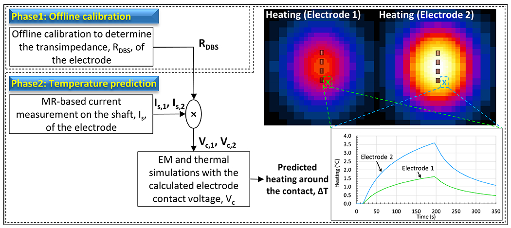
Workflow used for predicting RF-heating around the electrical contacts of bilateral DBS electrodes is shown. Temperature increase (ΔT) is simulated by using a simple model containing only the model of the electrical contacts (i.e. PEC cylinders) placed in a uniform gel medium.
2.1. Experimental setup and heating experiment
All experiments were performed in a 3T scanner (MAGNETOM Prisma, Siemens Healthineers, Erlangen, Germany) using the transmit body coil and the Siemens 20-Channel Head/Neck receiver coil. Figure 2 shows the phantom setup used in the experiments. The setup consisted of a skull phantom with a brain cavity and a head and torso phantom50–51. The skull component was made from clear resin, while the torso was made from polyethylene terephthalate glycol (PETG), both 3D printed in house. The distal ends of 30 cm (model 6171) and 40 cm (model 6173) DBS electrodes were fixed inside the skull phantom. The trajectories of the extracranial portion of the electrodes were modified to create different configurations. To minimize convective heat loss, both skull and torso phantoms were filled with hydroxyethyl cellulose gel (14 g/L)52–55. The resulting specific heat capacity and thermal conductivity were measured using a thermal properties analyzer (KD2 Pro, Decagon Devices, Pullman, WA), and determined to be 4200 J/¬kg-°C and 0.58 W/m-°C, respectively. The EM properties of the gel were measured using a dielectric assessment kit (DAK12, SPEAG, Zurich, Switzerland). The gel had a relative permittivity of 79 and a conductivity of 0.45 S/m, achieved by adding NaCl (2.25 g/L) to the gel mixture. Additionally, CuSO4 (0.25 g/L) was added to the mixture to reduce the T1 relaxation time.
Figure 2.
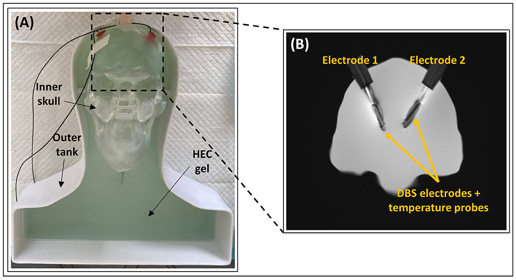
Experimental setup for the temperature prediction workflow. (A) The phantom consists of a removable inner skull and an outer tank. Both components were filled with hydroxyethyl cellulose (HEC) gel. (B) An MR coronal image showing the position of electrodes E1 and E2, and the temperature probes inside the brain cavity fixed with silicone stoppers (MR image shows a coronal slice of the brain cavity zoomed in with a ratio of 1:2.2).
The phantom setup was exposed to RF energy using a 3D turbo-spin echo (TSE) pulse sequence (TE = 103 ms, TA = 189 s, echo train length = 15, FA = 150°, in-plane resolution = 0.4 mm, slice thickness = 1.25 mm, and number of averages = 1), and the temperature increase near the contacts of the electrodes was measured in real-time using fluoroptic temperature probes (Lumasense Technologies, Santa Clara, CA) with a 0.5 s temporal resolution and 0.1 °C relative temperature measurement accuracy. The temperature probes were placed along the side of each electrode with the sensitive region aligned to the most distal contacts56. After each heating, the temperature at the vicinity of the electrode was allowed to cool down to a steady state (~18 °C). As circularly polarized (CP) mode is commonly used in MR scanners, most of the validation studies were performed with this mode of the body coil. Eight different extracranial electrode trajectories were tested. Contralateral (Traj #1, #4, and #8) and ipsilateral (Traj #2) configurations were investigated to test the workflow. In some of the trajectories, loops are introduced (Traj #3, #5 and #6) which is a surgical strategy that is investigated in the literature and shown to reduce contact temperature42. Furthermore, Traj #1 was chosen to investigate the accuracy of the workflow under additional RF excitation scenarios (i.e., linear excitation with Channel-1 and Channel-2). Finally, we tested the workflow in Traj #8, with the extension cables connected to the electrodes.
For visualization purposes only, we acquired 2D-GRE images (TR/TE = 456 ms/2.38 ms, FA = 75°, in-plane resolution = 0.625 mm, and slice thickness = 3 mm) in the transverse and coronal planes. These images were used for semi-automatic brain and electrode segmentations in 3D Slicer57 (www.slicer.org). The 3D segmentations were exported to a computer-aided design tool, Fusion 360 (Autodesk, San Rafael, CA) for electrode trajectory reconstruction. Rigid registration was performed to register the brain segmentations to the brain cavity of the skull phantom. The same transformation was used to register the electrodes to the skull model. A center line traced each electrode trajectory, and the body of the electrode was constructed around it. Manual refining of the center line was required for any overlapping electrode trajectories. Figure 3 shows the reconstructed 3D models of the DBS trajectories tested in this study. Note that electrode visualization, segmentation and 3D modeling are not required in the temperature prediction workflow and were only conducted to present different electrode configurations investigated in this work.
Figure 3.
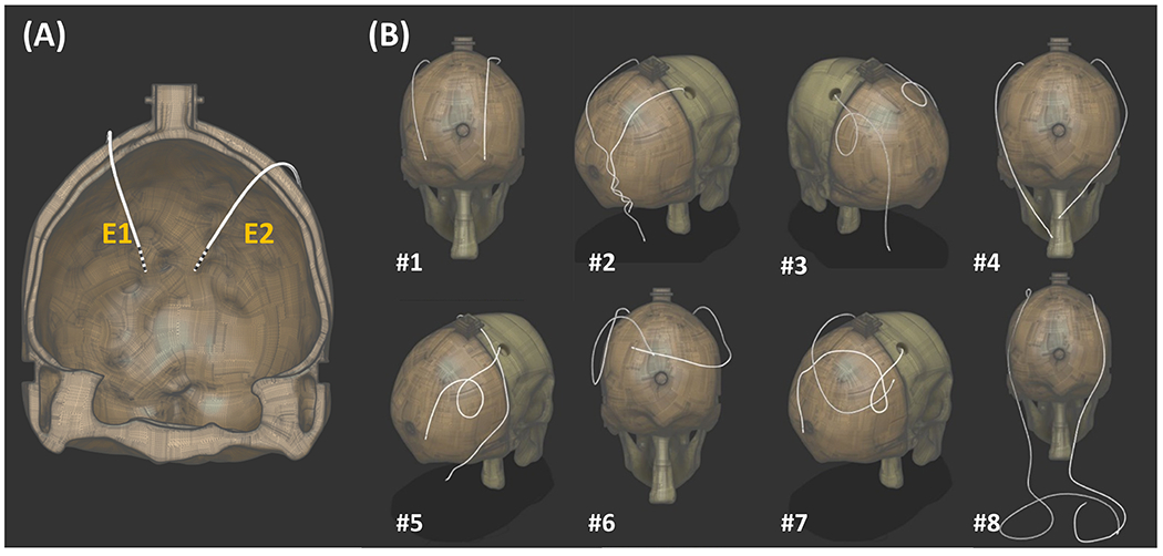
Bilateral electrode trajectories in the validation study. (A) The electrodes fixed in the skull component (temperature probes were not included in the model). (B) The trajectories for the extracranial portions of the electrodes were modified for each trajectory. Extension cables were connected to the electrodes in Traj #8.
2.2. Modified MR-based Current Measurement
Eryaman et al. demonstrated that RF-induced currents along a DBS electrode can be estimated using a geometric analysis of the null artifact, Tx-null, resulted from the incident B1+ field canceling with the B1+ field generated by the electrode46. Sadeghi-Tarakameh et al. expanded the general induced current formulation to include the polar and azimuthal angles and , of electrodes in oblique orientations45. The induced current, denoted, , can be calculated with the following equation,
| (1) |
In the unilateral DBS validation and heating predictions, the MR images for Tx-null and incident field measurements were both acquired in transverse plane, as shown in Figure 4A.
Figure 4.

DBS orientation and imaging planes for induced current estimation. P1img and P2img are imaging planes for Tx-null measurement and B1 mapping. (A) DBS electrodes aligned parallel to the z-axis with transverse P1img and P2img. (B) Oblique DBS electrodes with modified P1img and P2img. P1img is an oblique plane orthogonal to the electrode. It contains the Tx-null coinciding with P1ref, a transverse plane 30 mm from the DBS tip. P2img is a transverse plane that intersects the shifted position of the Tx-null in P2ref, an oblique plane underneath the DBS tip. (C) 3D-GRE image in P1img showing the Tx-null, rn mm away from the electrode and with an azimuthal angle of ϕn. (D) B1 map obtained at P2img and the 5 × 5 mm2 ROI used to measure the mean incident B1+.
The increased complexity resulting from the addition of the second electrode, the obliqueness of both electrodes and the shape of the skull require modifications to the current measurement method, as illustrated in Figure 4B, to sustain accuracy for Tx-null measurement and prevent interference from current flowing on the electrode during the incident B1+ measurement. In addition to the imaging planes, we included reference planes which need to be identified for both the incident B1+ and Tx-null measurements. In this study, the planes used in the Tx-null measurement were defined as P1, and the planes used in B1 mapping were defined as P2. A subscript of “ref” denotes the plane as a reference plane, and a subscript “img” denotes it as an imaging plane.
In the Tx-null measurement, the first step involved identifying P1ref, a transverse plane positioned 30 mm above the DBS tip. Next, a multi-slice 3D-GRE scan (TR/TE = 20 ms/2.64 ms, TA = 65 s, FA = 20°, in-plane resolution = 0.5 mm, slice thickness = 3 mm) was acquired in P1img, an oblique plane orthogonal to the orientation of the electrode. Following that, the image slice with the Tx-null coinciding with P1ref, such as Figure 4C, was selected and the radial distance of Tx-null, rn was measured.
For the measurement, P2ref, an oblique plane below the electrode tip and parallel to P1img was identified. The Tx-null position was then shifted along the z-axis to align with P2ref while maintaining the same x-y coordinates. A low-power pre-saturated turbo-flash B1 map sequence (TR/TE = 10000 ms/2.24 ms, TA = 15s, nominal FA = 80°, readout FA = 20°) was acquired in P2img, a transverse plane intersecting the shifted Tx-null position. A 5 × 5 mm2 region-of-interest (ROI) centered on the shifted Tx-null position was used to measure the mean value of the incident field, . Figure 4D shows the resulting B1map acquired in P2img and the ROI used in the measurement.
2.3. RF Heating Prediction
Numerical quasi-static EM and transient thermal simulations in Sim4life (Zurich Medtech, Zurich, Switzerland) were performed to predict the RF heating around the DBS contacts. As shown in Figure 5 the electro quasi-static simulation model consists of four perfect electrical conductor (PEC) cylinders with the dimension of the DBS contacts under study, and a lossy medium with properties similar to the measured dielectric properties of the HEC gel. The PEC cylinders were assigned a Dirichlet boundary voltage of Vc, obtained by calculating the product of the transimpedance, RDBS. and the induced current. The RDBS value for the DBS electrodes used in this study was previously determined to be 88 Ω45. 0 V was assigned to the surfaces of a large rectangular prism surrounding the simulation model (49 cm × 77 cm × 130 cm). Sim4Life’s meshing toolbox was used to discretize the PEC cylinders with “extremely fine” setting while everything else was discretized with the “fine” setting. The EM simulation solved for specific absorption rate given by,
| (2) |
where and are the conductivity and the mass density of the medium and is the amplitude of the electric field at location .
Figure 5.
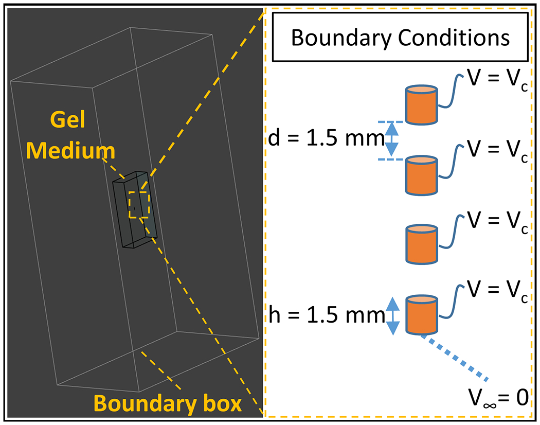
EM simulation environment. The simulation model consists of four perfect electrical conductors as the electrode contacts and a gel medium (occupying 0.5 % of the volume of a boundary box which represents infinity). Vc is assigned as the voltage boundary conditions of the contacts and zero potential at infinity.
The resulting SAR distribution became the input for the transient thermal simulation to solve Pennes’ bioheat equation58 with the absence of perfusion and metabolic heat generation, given by
| (3) |
where and are the specific heat capacity and thermal conductivity of the medium. The simulation time was set to 350 s which includes the 15s before the heat was applied (equilibrium), the time when the heat source is on (similar to the TSE acquisition time of 189 s) and the time when the setup is cooling down. Because the location of the simulated temperature rise needs to match the location of the temperature probe during the TSE-induced heating experiments, the radial distance of the temperature probe tip from the center of each electrode was measured in 3D Slicer as demonstrated in Figure 6. The measured and the simulated time progression of temperature increase, ΔTexp and ΔTsim were recorded and their difference was quantified using the root-mean-squared error (RMSE) metric.
Figure 6.

Temperature probe localization in 3D Slicer. The distance between the temperature probe and the center of the electrode was measured for each trajectory to ensure the locations of the heating prediction match the locations of the temperature probe.
2.4. Uncertainty in Heating Prediction
In predicting the RF heating around the contacts, the uncertainty of the calculated Vc, which is contributed by uncertainties in Is and RDBS, is considered59. The uncertainty in Is depends on the resolution of the image used to measure the null distance (0.5 mm for all results). In general, the uncertainty for a given experiment can be expressed as
| (4) |
Similarly, the uncertainty in RDBS stems from the calibration study conducted in the previous work46. Taking into account the image resolution of 0.5 mm and rnull values of 4.9 mm from the earlier study, the uncertainty can be calculated as:
| (5) |
Since Vc is the product of Is and RDBS, and both parameters are independent of each other, , can be expressed as
| (6) |
The heating exhibits linear relationship with SAR and a quadratic relationship with Vc, yielding to an uncertainty propagation of,
| (7) |
3. Results
Figure 7 shows ΔTsim and ΔTexp for two electrodes and 8 different trajectories. A quantitative agreement was obtained for all heating scenarios. The RMSE was determined as 0.29 °C and 0.21 °C for electrodes 1 and 2 respectively.
Figure 7.

Comparisons between the experimentally measured and simulated heating of bilateral DBS exposed to circularly polarized (CP) mode in Trajectories 1-8.
Figure 8 shows ΔTsim and ΔTexp for Traj #1 exposed to two linear excitations (Channel 1-only and Channel 2-only). Similar to CP excitation, a quantitative agreement was obtained. The RMSE was determined as 0.16 °C and 0.15 °C for electrodes 1 and 2 respectively.
Figure 8.

Comparisons between the experimentally measured and simulated heating of bilateral DBS exposed to Channel 1-only and Channel 2-only excitations (electrodes in Traj #1).
Table 1 shows ΔTsim and ΔTexp measured at the end of TSE sequence as well as the measured shaft current Is for both electrodes. Temperature measurement device-related error for ΔTexp was ≤ 0.25 °C for our studies.
Table 1.
Experimentally measured and simulated heating at the end of TSE sequence, ΔTexp and ΔTsim, and the induced current along the DBS electrodes, Is, for both DBS electrodes in each trajectory and excitation (for electrodes in Traj #1).
| Electrode 1 | Electrode 2 | |||||
|---|---|---|---|---|---|---|
|
| ||||||
| ΔTexp (°C) | ΔTsim (°C) | Is1 (mA) | ΔTexp (°C) | ΔTsim (°C) | Is2 (mA) | |
|
| ||||||
| CP mode | ||||||
| Traj #1 | 3.8 | 3.8 ± 1.0 | 205.9 ± 15.8 | 0.7 | 0.8 ± 0.4 | 79.4 ± 17.3 |
| Traj #2 | 2.4 | 2.3 ± 0.6 | 160.0 ± 14.2 | 4.8 | 5.0 ± 1.3 | 197.8 ± 16.8 |
| Traj #3 | 1.1 | 0.7 ± 0.3 | 85.8 ± 15.8 | 0.5 | 0.3 ± 0.2 | 47.9 ± 15.2 |
| Traj #4 | 1.7 | 1.6 ± 0.5 | 124.8 ± 14.9 | 1.2 | 1.2 ± 0.4 | 111.3 ± 15.9 |
| Traj #5 | 1.7 | 2.1 ± 0.6 | 145.3 ± 14.2 | 0.2 | 0.5 ± 0.3 | 68.6 ± 18.1 |
| Traj #6 | 0.1 | 0.1 ± 0.1 | 29.8 ± 14.9 | 1.4 | 1.3 ± 0.7 | 68.0 ± 17.1 |
| Traj #7 | 0.1 | 0.3 ± 0.2 | 53.7 ± 15.8 | 0.0 | 0.2 ± 0.2 | 42.6 ± 16.6 |
| Traj #8 | 3.5 | 3.4 ± 1.0 | 150.9 ± 15.6 | 0.3 | 0.4 ± 0.2 | 75.1 ± 15.6 |
|
| ||||||
| Traj #1 | ||||||
| Ch 1-only | 5.0 | 5.2 ± 1.1 | 238.6 ± 9.7 | 2.6 | 2.5 ± 0.7 | 138.8 ± 12.3 |
| Ch 2-only | 0.3 | 0.2 ± 0.1 | 46.3 ± 12.2 | 2.4 | 2.6 ± 0.6 | 143.2 ± 10.3 |
4. Discussion
DBS-related heating in MRI is a serious safety concern. Falowski et al.60 estimated 66-75 % of patients with DBS implants will require an MRI scan within 10 years post-implantation. Therefore, accurate heating assessment is critical to allow medically required MRI examinations for DBS-implanted patients. Our proposed RF heating prediction workflow provides a patient-specific solution and may allow safe scanning of patients with DBS implants. Figure 9 shows the summary of the steps that can be taken to scan patients. First a pre-scan using conventional GRE and B1 mapping protocols is conducted to measure the RF induced shaft current on the electrodes. The measured current is then used to predict perfusion-free RF heating, ΔTperf-free, around the DBS contacts, providing a thermally worst-case estimation for the actual heating. Next, the RF power of the imaging protocol is adjusted via modifying imaging parameters to ensure that ΔTperf-free remains within a pre-determined heating cutoff, ΔTcut-off. An acceptable value for ΔTcut-off can be determined from the difference between the maximum local temperature limit of 39 °C in the head61 and the patient’s body temperature. The patient body temperature can be measured for each patient before the scan for this purpose, which is already in accordance with DBS manufacturer’s scanning guidelines21
Figure 9.

Proposed workflow for safe MRI scanning for patients with deep brain stimulation (DBS) implants. Starting with a pre-scan to estimate the induced RF current along the DBS electrodes, perfusion-free heating (thermally worst-case scenario) around DBS contacts is predicted. RF power is normalized accordingly to ensure the absolute tissue temperature around the contacts do not exceed IEC tissue temperature limits.
The EM and thermal simulations are performed once to generate all the temperature results in this work. The linearity of the EM medium allowed us to simply scale the voltage boundary conditions used in the quasi-static simulations to solve the electric field and SAR around the electrical contacts. The linearity between ΔT and SAR in the bio-heat equation allows us to scale the temperature distribution with respect to the square of the voltage. If the proposed workflow is to be used in clinical imaging, these two linearity features would be very important as they eliminate the necessity to conduct EM/thermal simulations for each patient. One sufficiently long thermal simulation can be performed offline, and the resulting ΔT can be scaled with the square of the voltage obtained by multiplying the shaft current and the transimpedance value. Finally, ΔT from the long thermal simulation can be used to assess the temperature for shorter scan durations.
The shaft current, Is, denotes the total induced current flowing on the shaft of the electrode. This is different from the current flowing in the wires connecting to each contact. For this particular DBS model, Sadeghi-Tarakameh et.al demonstrated that measuring only the total shaft current and using a single calibrated transimpedance value was sufficient to predict the heating around all contacts45. In principle, different transimpedance values can be assigned to each individual contact of the electrode if needed. Regardless, our workflow would still be viable to determine the individual transimpedance values.
The dielectric properties of the phantom were consistent with other literature discussing DBS heating62–63. The relationship between transimpedance and medium EM properties is not investigated in this work. If this method is to be applied to clinical imaging, it would be important to conduct such an investigation and measure the dependence of transimpedance on permittivity and conductivity. In this work, the dielectric and thermal properties of the phantom were kept constant during the experiments. Therefore, the primary source of uncertainty was due to MR-based current measurement. For in-vivo studies, a comprehensive statistical analysis involving tissue dielectric and thermal property variations will be necessary to assess the uncertainty in heating.
The workflow was validated in an anthropomorphic human head phantom which mimics a limited degree of tissue inhomogeneity although more than a uniform phantom. For example, a realistic skull model was included in our anthropomorphic head phantom which was not part of the previous unilateral validation study45.
Fluoroptic temperature probes were utilized to assess the heating around the DBS contacts due to the high temporal resolution compared to other techniques such as MR thermometry and infrared cameras. The effect of the presence of a temperature probe on heat transfer was not investigated. The results of heating prediction in a perfusion-free scenario constitute a thermally worst-case heating scenario. Perfusion can also be added to the simulation if needed. This would be particularly important to test the workflow in more realistic scenarios such as in-vivo animal studies.
We previously demonstrated that the equivalent transimpedance is independent of electrode trajectories, the addition of extension cables, and RF excitation scenarios. This hypothesis is proven again in this bilateral study where good agreement between the measured and simulated heating is observed. The transimpedance value used in this study was determined during calibration in our previous study45. The calibration work was performed for a unilateral 40 cm electrode of the same model in a box-shaped phantom. Despite using bilateral DBS electrodes of different lengths (30 cm and 40 cm) and using a phantom with increased complexity in shape, no additional calibration was required. These agreements suggest that the equivalent transimpedance of a specific model of DBS electrode can be determined in an offline calibration using a simple setting and yet can still provide an accurate prediction of heating around the DBS contacts in more complex and realistic experimental settings. Further investigation is necessary to understand how the transimpedance would change with electrode geometry, i.e. diameter or/and the separation distance between the electrical contacts, and materials used. Because this concerns patient safety, we recommend researchers validate this workflow with their own hardware and electrodes before any in-vivo applications
5. Conclusion
We demonstrated that RF heating around bilateral electrodes can be predicted with a temperature prediction workflow specifically modified for this problem. A quantitative agreement (RMSE ≤ 0.29 °C) was achieved across temperature data obtained from electrodes with different trajectories in an anthropomorphic head phantom. The uncertainties in temperature prediction were modeled and quantified. The workflow can provide a conservative estimate of the actual heating around the DBS contacts, potentially serving as a valuable tool to monitor patient safety during MRI scans.
Acknowledgement
National Institute of Biomedical Imaging and Bioengineering, Grant/Award Number: P41 EB027061; National Institute of Neurological Disorders and Stroke, Grant/Award Number: R01NS115180. The authors thank Dr. Xiaoxuan He for his help and collaboration in the work of the predecessor of this study.
Footnotes
Conflict of Interest Statement
The authors have no relevant conflicts of interest to disclose.
Reference
- 1.Gupte AA, Shrivastava D, Spaniol MA, Abosch A. MRI-related heating near deep brain stimulation electrodes: more data are needed. Stereotact Funct Neurosurg. 2011;89(3):131–140. doi: 10.1159/000324906 [DOI] [PMC free article] [PubMed] [Google Scholar]
- 2.Nitz WR, Oppelt A, Renz W, Manke C, Lenhart M, Link J. On the heating of linear conductive structures as guide wires and catheters in interventional MRI. J Magn Reson Imaging. 2001;13(1):105–114. doi:10.1002/1522-2586(200101)13:1<105::aid-jmri1016>3.0.co;2-00, https://doi.org/10.1002/1522-2586(200101)13:1<105::aid-jmri1016>3.0.co;2-0 [DOI] [PubMed] [Google Scholar]
- 3.Cho Y, Yoo H. RF Heating of Implants in MRI: Electromagnetic Analysis and Solutions. Investigative Magnetic Resonance Imaging. Korean Society of Magnetic Resonance in Medicine. 2020;24(2):67–75. 10.13104/imri.2020.24.2.67 [DOI] [Google Scholar]
- 4.Winter L, Seifert F, Zilberti L, Murbach M, Ittermann B. MRI-Related Heating of Implants and Devices: A Review. J Magn Reson Imaging. 2021;53(6):1646–1665. doi: 10.1002/jmri.27194 [DOI] [PubMed] [Google Scholar]
- 5.Groiss SJ, Wojtecki L, Südmeyer M, Schnitzler A. Deep brain stimulation in Parkinson’s disease. Ther Adv Neurol Disord. 2009;2(6):20–28. doi: 10.1177/1756285609339382 [DOI] [PMC free article] [PubMed] [Google Scholar]
- 6.Lozano AM, Lipsman N. Probing and regulating dysfunctional circuits using deep brain stimulation. Neuron. 2013;77(3):406–424. doi: 10.1016/j.neuron.2013.01.020 [DOI] [PubMed] [Google Scholar]
- 7.Hu W, Stead M. Deep brain stimulation for dystonia. Transl Neurodegener. 2014;3(1):2. Published 2014 Jan 21. doi: 10.1186/2047-9158-3-2 [DOI] [PMC free article] [PubMed] [Google Scholar]
- 8.Holtzheimer PE, Mayberg HS. Deep brain stimulation for psychiatric disorders. Annu Rev Neurosci. 2011;34:289–307. doi: 10.1146/annurev-neuro-061010-113638 [DOI] [PMC free article] [PubMed] [Google Scholar]
- 9.Kahn L, Sutton B, Winston HR, Abosch A, Thompson JA, Davis RA. Deep Brain Stimulation for Obsessive-Compulsive Disorder: Real World Experience Post-FDA-Humanitarian Use Device Approval. Front Psychiatry. 2021;12:568932. Published 2021 Mar 24. doi: 10.3389/fpsyt.2021.568932 [DOI] [PMC free article] [PubMed] [Google Scholar]
- 10.Zanchi MG, Venook R, Pauly JM, Scott GC. An optically coupled system for quantitative monitoring of MRI-induced RF currents into long conductors. IEEE Trans Med Imaging. 2010;29(1):169–178. doi: 10.1109/TMI.2009.2031558 [DOI] [PMC free article] [PubMed] [Google Scholar]
- 11.Dempsey MF, Condon B, Hadley DM. Investigation of the factors responsible for burns during MRI. J Magn Reson Imaging. 2001;13(4):627–631. doi: 10.1002/jmri.1088 [DOI] [PubMed] [Google Scholar]
- 12.Yeung CJ, Susil RC, Atalar E. RF heating due to conductive wires during MRI depends on the phase distribution of the transmit field. Magn Reson Med. 2002;48(6):1096–1098. doi: 10.1002/mrm.10310 [DOI] [PubMed] [Google Scholar]
- 13.Angelone LM, Vasios CE, Wiggins G, Purdon PL, Bonmassar G. On the effect of resistive EEG electrodes and leads during 7 T MRI: simulation and temperature measurement studies. Magn Reson Imaging. 2006;24(6):801–812. doi: 10.1016/j.mri.2006.01.006 [DOI] [PubMed] [Google Scholar]
- 14.Oluigbo CO, Rezai AR. Magnetic resonance imaging safety of deep brain stimulator devices. Handb Clin Neurol. 2013;116:73–76. doi: 10.1016/B978-0-444-53497-2.00007-3 [DOI] [PubMed] [Google Scholar]
- 15.Henderson JM, Tkach J, Phillips M, Baker K, Shellock FG, Rezai AR. Permanent neurological deficit related to magnetic resonance imaging in a patient with implanted deep brain stimulation electrodes for Parkinson’s disease: case report. Neurosurgery. 2005;57(5):E1063. doi: 10.1227/01.neu.0000180810.16964.3e [DOI] [PubMed] [Google Scholar]
- 16.Spiegel J, Fuss G, Backens M, et al. Transient dystonia following magnetic resonance imaging in a patient with deep brain stimulation electrodes for the treatment of Parkinson disease. Case report. J Neurosurg. 2003;99(4):772–774. doi: 10.3171/jns.2003.99.4.0772 [DOI] [PubMed] [Google Scholar]
- 17.Rezai AR, Phillips M, Baker KB, et al. Neurostimulation system used for deep brain stimulation (DBS): MR safety issues and implications of failing to follow safety recommendations. Invest Radiol. 2004;39(5):300–303. doi: 10.1097/01.rli.0000124940.02340.ab [DOI] [PubMed] [Google Scholar]
- 18.Boutet A, Chow CT, Narang K, et al. Improving Safety of MRI in Patients with Deep Brain Stimulation Devices. Radiology. 2020;296(2):250–262. doi: 10.1148/radiol.2020192291 [DOI] [PMC free article] [PubMed] [Google Scholar]
- 19.Baker KB, Tkach JA, Nyenhuis JA, et al. Evaluation of specific absorption rate as a dosimeter of MRI-related implant heating. J Magn Reson Imaging. 2004;20(2):315–320. doi: 10.1002/jmri.20103 [DOI] [PubMed] [Google Scholar]
- 20.Rezai AR, Finelli D, Nyenhuis JA, et al. Neurostimulation systems for deep brain stimulation: in vitro evaluation of magnetic resonance imaging-related heating at 1.5 tesla. J Magn Reson Imaging. 2002;15(3):241–250. doi: 10.1002/jmri.10069 [DOI] [PubMed] [Google Scholar]
- 21.Abbott. MRI Procedure Information, Abbott Medical MR Conditional Deep Brain Stimulation Systems. Clinician’s Manual. https://manuals.sjm.com/Search-Form?re=North-America&cc=US&ln=EN&ct=professional&qry=3664&ipp=10. Accessed April 2023
- 22.Baker KB, Tkach JA, Phillips MD, Rezai AR. Variability in RF-induced heating of a deep brain stimulation implant across MR systems. J Magn Reson Imaging. 2006;24(6):1236–1242. doi: 10.1002/jmri.20769 [DOI] [PubMed] [Google Scholar]
- 23.Boutet A, Hancu I, Saha U, et al. 3-Tesla MRI of deep brain stimulation patients: safety assessment of coils and pulse sequences. J Neurosurg. 2019;132(2):586–594. doi: 10.3171/2018.11.JNS181338 [DOI] [PubMed] [Google Scholar]
- 24.Carmichael DW, Pinto S, Limousin-Dowsey P, et al. Functional MRI with active, fully implanted, deep brain stimulation systems: safety and experimental confounds. Neuroimage. 2007;37(2):508–517. doi: 10.1016/j.neuroimage.2007.04.058 [DOI] [PubMed] [Google Scholar]
- 25.Rezai AR, Finelli D, Nyenhuis JA, et al. Neurostimulation systems for deep brain stimulation: in vitro evaluation of magnetic resonance imaging-related heating at 1.5 tesla. J Magn Reson Imaging. 2002;15(3):241–250. doi: 10.1002/jmri.10069 [DOI] [PubMed] [Google Scholar]
- 26.Boutet A, Elias GJB, Gramer R, et al. Safety assessment of spine MRI in deep brain stimulation patients [published online ahead of print, 2020 Feb 14]. J Neurosurg Spine. 2020;1–11. doi: 10.3171/2019.12.SPINE191241 [DOI] [PubMed] [Google Scholar]
- 27.Park SM, Kamondetdacha R, Nyenhuis JA. Calculation of MRI-induced heating of an implanted medical lead wire with an electric field transfer function. J Magn Reson Imaging. 2007;26(5):1278–1285. doi: 10.1002/jmri.21159 [DOI] [PubMed] [Google Scholar]
- 28.Tokaya JP, Raajimakers AJE, Luijten PR, Sbrizzi A, van den Berg CAT. MRI-based transfer function determination through the transfer matrix by jointly fitting the incident and scattered B1+ field. Magn Reson Med. 2020;83(3):1081–1095. Doi: 10.1002/mrm.27974 [DOI] [PMC free article] [PubMed] [Google Scholar]
- 29.ISO Assessment of the safety of magnetic resonance imaging for patients with an active implantable medical device. ISO/TS 10974:2018. Int. Organ. Stand 2018;2018 [Google Scholar]
- 30.Christ A, Kainz W, Hahn EG, et al. The Virtual Family – development of surface-based anatomical models of two adults and two children for dosimetric simulations. Phys Med Biol. 2010;55(2):N23–N38. DOI: 10.1088/0031-9155/55/2/N01 [DOI] [PubMed] [Google Scholar]
- 31.Kazemivalipour E, Sadeghi-Tarakameh A, Keil B, Eryaman Y, Atalar E, Golestanirad L. Effect of field strength on RF power deposition near conductive leads: A simulation study of SAR in DBS lead models during MRI at 1.5 T-10.5 T. PLoS One. 2023. Jan 26;18(1):e0280655. doi: 10.1371/journal.pone.0280655. [DOI] [PMC free article] [PubMed] [Google Scholar]
- 32.Iacono MI, Makris N, Mainardi L, Angelone LM, Bonmassar G. MRI-based multiscale model for electromagnetic analysis in the human head with implanted DBS. Comput Math Methods Med. 2013;2013:694171. doi: 10.1155/2013/694171 [DOI] [PMC free article] [PubMed] [Google Scholar]
- 33.Guerin B, Iacono MI, Davids M, Dougherty D, Angelone LM, Wald LL. The ‘virtual DBS population’: five realistic computational models of deep brain stimulation patients for electromagnetic MR safety studies. Phys Med Biol. 2019;64(3):035021. Published 2019 Feb 4. doi: 10.1088/1361-6560/aafce8 [DOI] [PMC free article] [PubMed] [Google Scholar]
- 34.Bonmassar G, Angelone LM, Makris N. A Virtual Patient Simulator Based on Human Connectome and 7 T MRI for Deep Brain Stimulation. Int J Adv Life Sci. 2014;6(3-4):364–372. [PMC free article] [PubMed] [Google Scholar]
- 35.Liu J, Zheng J, Zeng Q, Wang Q, Rondoni J, Olsen J, Kainz W and Chen J 2019. Investigations on tissue-simulating medium for MRI RF safety assessment for patients with active implantable medical devices IEEE Trans. Electromagn. Compat 61 1091–7 [Google Scholar]
- 36.Sanpitak P, Bhusal B, Nguyen BT, Vu J, Chow K, Bi X, Golestanirad L. On the accuracy of Tier 4 simulations to predict RF heating of wire implants during magnetic resonance imaging at 1.5 T. 2021 43rd Annual International Conference of the IEEE Engineering in Medicine & Biology Society (EMBC), Mexico, 2021, pp. 4982–4985, doi: 10.1109/EMBC46164.2021.9630220. [DOI] [PubMed] [Google Scholar]
- 37.Vu J, Nguyen BT, Bhusal B, et al. Machine learning-based prediction of MRI-induced power absorption in the tissue in patients with simplified deep brain stimulation lead models. IEEE Trans Electromagn Compat. 2021;63(5):1757–1766. doi: 10.1109/temc.2021.3106872 [DOI] [PMC free article] [PubMed] [Google Scholar]
- 38.Zheng C, Chen X, Nguyen BT, Sanpitak P, Vu J, Ulas Bagci, Golestanirad L. Predicting RF Heating of Conductive Leads During Magnetic Resonance Imaging at 1.5 T: A Machine Learning Approach. 2021 43rd Annual International Conference of the IEEE Engineering in Medicine & Biology Society (EMBC), Mexico, 2021, pp. 4204–4208, doi: 10.1109/EMBC46164.2021.9630718. [DOI] [PMC free article] [PubMed] [Google Scholar]
- 39.Guo R, Zheng J, Kainz W and Chen J. Predicting RF-Induced Heating for Deep Brain Stimulator System Using an Artificial Neural Network. 2022 International Conference on Cyber-Physical Social Intelligence (ICCSI), Nanjing, China, 2022, pp. 423–428, doi: 10.1109/ICCSI55536.2022.9970664. [DOI] [Google Scholar]
- 40.Golestanirad L, Angelone LM, Iacono MI, Katnani H, Wald LL, Bonmassar G. Local SAR near deep brain stimulation (DBS) electrodes at 64 and 127 MHz: A simulation study of the effect of extracranial loops. Magn Reson Med. 2017;78(4):1558–1565. doi: 10.1002/mrm.26535 [DOI] [PMC free article] [PubMed] [Google Scholar]
- 41.Guerin B, Serano P, Iacono MI, et al. Realistic modeling of deep brain stimulation implants for electromagnetic MRI safety studies. Phys Med Biol. 2018;63(9):095015. Published 2018 May 4. doi: 10.1088/1361-6560/aabd50 [DOI] [PMC free article] [PubMed] [Google Scholar]
- 42.Golestanirad L, Kirsch J, Bonmassar G, et al. RF-induced heating in tissue near bilateral DBS implants during MRI at 1.5 T and 3T: The role of surgical lead management. Neuroimage. 2019;184:566–576. doi: 10.1016/j.neuroimage.2018.09.034Machinelearning [DOI] [PMC free article] [PubMed] [Google Scholar]
- 43.Thani NB, Bala A, Swann GB, Lind CR. Accuracy of postoperative computed tomography and magnetic resonance image fusion for assessing deep brain stimulation electrodes. Neurosurgery. 2011;69(1):207–214. [DOI] [PubMed] [Google Scholar]
- 44.Nguyen BT, Pilitsis J, Golestanirad L. The effect of simulation strategies on prediction of power deposition in the tissue around electronic implants during magnetic resonance imaging. Phys Med Biol. 2020;65(18):185007. Published 2020 Sep 16. doi: 10.1088/1361-6560/abac9f [DOI] [PMC free article] [PubMed] [Google Scholar]
- 45.Sadeghi-Tarakameh A, Zulkarnain NIH, He X, Atalar E, Harel N, Eryaman Y. A workflow for predicting temperature increase at the electrical contacts of deep brain stimulation electrodes undergoing MRI. Magn Reson Med. 2022;88(5):2311–2325. doi: 10.1002/mrm.29375 [DOI] [PMC free article] [PubMed] [Google Scholar]
- 46.Eryaman Y, Kobayashi N, Moen S, et al. A simple geometric analysis method for measuring and mitigating RF induced currents on Deep Brain Stimulation leads by multichannel transmission/reception. Neuroimage. 2019;184:658–668. doi: 10.1016/j.neuroimage.2018.09.072 [DOI] [PMC free article] [PubMed] [Google Scholar]
- 47.Petraglia FW 3rd, Farber SH, Han JL, et al. Comparison of Bilateral vs. Staged Unilateral Deep Brain Stimulation (DBS) in Parkinson’s Disease in Patients Under 70 Years of Age. Neuromodulation. 2016;19(1):31–37. doi: 10.1111/ner.12351 [DOI] [PMC free article] [PubMed] [Google Scholar]
- 48.Prakash P, Deuschl G, Ozinga S, et al. Benefits and Risks of a Staged-Bilateral VIM Versus Unilateral VIM DBS for Essential Tremor. Mov Disord Clin Pract. 2022;9(6):775–784. Published 2022 Jun 14. doi: 10.1002/mdc3.13490 [DOI] [PMC free article] [PubMed] [Google Scholar]
- 49.Tanei T, Kajita Y, Kaneoke Y, Takebayashi S, Nakatsubo D, Wakabayashi T. Staged bilateral deep brain stimulation of the subthalamic nucleus for the treatment of Parkinson’s disease. Acta Neurochir (Wien). 2009;151(6):589–594. doi: 10.1007/s00701-009-0293-6 [DOI] [PubMed] [Google Scholar]
- 50.Guérin B, Stockmann JP, Baboli M, Torrado-Carvajal A, Stenger AV, Wald LL. Robust time-shifted spoke pulse design in the presence of large B0 variations with simultaneous reduction of through-plane dephasing, B1+ effects, and the specific absorption rate using parallel transmission. Magn Reson Med. 2016;76(2):540–554. doi: 10.1002/mrm.25902 [DOI] [PMC free article] [PubMed] [Google Scholar]
- 51.Yang B, Tam F, Davidson B, et al. Technical note: An anthropomorphic phantom with implanted neurostimulator for investigation of MRI safety. Medical Physics. 2020;47(8):3745–3751. doi: 10.1002/mp.14214 [DOI] [PubMed] [Google Scholar]
- 52.Erhardt JB, Lottner T, Martinez J, et al. It’s the little things: On the complexity of planar electrode heating in MRI. Neuroimage. 2019;195:272–284. doi: 10.1016/j.neuroimage.2019.03.061 [DOI] [PMC free article] [PubMed] [Google Scholar]
- 53.Acikel V, Uslubas A, Atalar E. Modeling of electrodes and implantable pulse generator cases for the analysis of implant tip heating under MR imaging. Med Phys. 2015;42(7):3922–3931. doi: 10.1118/1.4921019 [DOI] [PubMed] [Google Scholar]
- 54.Ehses P, Fidler F, Nordbeck P, et al. MRI thermometry: Fast mapping of RF-induced heating along conductive wires. Magn Reson Med. 2008;60(2):457–461. doi: 10.1002/mrm.21417 [DOI] [PubMed] [Google Scholar]
- 55.Mattei E, Triventi M, Calcagnini G, et al. Complexity of MRI induced heating on metallic leads: experimental measurements of 374 configurations. Biomed Eng Online. 2008;7:11. Published 2008 Mar 3. doi: 10.1186/1475-925X-7-11 [DOI] [PMC free article] [PubMed] [Google Scholar]
- 56.Mattei E, Triventi M, Calcagnini G, et al. Temperature and SAR measurement errors in the evaluation of metallic linear structures heating during MRI using fluoroptic probes. Phys Med Biol. 2007;52(6):1633–1646. doi: 10.1088/0031-9155/52/6/006 [DOI] [PubMed] [Google Scholar]
- 57.Kikinis R, Pieper SD, Vosburgh K (2014) 3D Slicer: a platform for subject-specific image analysis, visualization, and clinical support. Intraoperative Imaging Image-Guided Therapy, Jolesz Ferenc A., Editor 3(19):277–289 ISBN: 978-1-4614-7656-6 (Print) 978-1-4614-7657-3 (Online) [Google Scholar]
- 58.Pennes HH. Analysis of tissue and arterial blood temperatures in the resting human forearm. 1948. J Appl Physiol (1985). 1998;85(1):5–34. doi: 10.1152/jappl.1998.85.1.5 [DOI] [PubMed] [Google Scholar]
- 59.Bonamente M Error Propagation and Simulation of Random Variables. In: Statistics and Analysis of Scientific Data. Springer; 2022. [Google Scholar]
- 60.Falowski S, Safriel Y, Ryan MP, Hargens L. The Rate of Magnetic Resonance Imaging in Patients with Deep Brain Stimulation. Stereotact Funct Neurosurg. 2016;94(3):147–153. doi: 10.1159/000444760 [DOI] [PubMed] [Google Scholar]
- 61.IEC. IEC 60601-2-33. Medical electrical equipment – Part 2-33: Particular requirements for the basic safety and essential performance of magnetic resonance equipment for medical diagnosis. 2015 [Google Scholar]
- 62.Bhusal B, Nguyen BT, Sanpitak PP, et al. Effect of Device Configuration and Patient’s Body Composition on the RF Heating and Nonsusceptibility Artifact of Deep Brain Stimulation Implants During MRI at 1.5T and 3T. J Magn Reson Imaging. 2021;53(2):599–610. doi: 10.1002/jmri.27346 [DOI] [PubMed] [Google Scholar]
- 63.Vu J, Bhusal B, Nguyen BT, et al. A comparative study of RF heating of deep brain stimulation devices in vertical vs. horizontal MRI systems. PLoS One. 2022;17(12):e0278187. Published 2022 Dec 9. doi: 10.1371/journal.pone.0278187 [DOI] [PMC free article] [PubMed] [Google Scholar]