

Abstract
An autonomous, power-assisted Turtlebot is presented in this paper in order to enhance human mobility. The turtlebot moves from its initial position to its final position at a predetermined speed and acceleration. We propose an intelligent navigation system that relies solely on individual instructions. When there is no individual present, the Turtlebot remains stationary. Turtlebot utilizes a rotating Kinect sensor in order to perceive its path. Various angles were examined in order to demonstrate the effectiveness of the system in experiments conducted on a U-shaped experimental pathway. The Turtlebot was used as an experimental device during these trials. Based on the U-shaped path, deviations from different angles were measured to evaluate its performance. SLAM (Simultaneous Localization and Mapping) experiments were also explored. We divided the SLAM problem into components and implemented the Kalman filter on the experimental path to address it. The Kalman filter focused on localization and mapping challenges, utilizing mathematical processes considering both the system's knowledge and the measurement tool. This approach allowed us to achieve the most accurate system state estimation possible. The significance of this work extends beyond the immediate application, as it lays the groundwork for advancements in wheelchair navigation research by Dynamic Control. The experiments conducted on a U-shaped pathway not only validate the efficacy of our algorithm but also provide valuable insights into the intricacies of navigating in both forward and reverse directions. These insights are pivotal for refining the navigation algorithm, ultimately contributing to the development of more robust and user-friendly systems for individuals with mobility challenges. The data used for this purpose included actuator input, vehicle location, robot movement sensors, and sensor readings representing the world state. The study provides a strong foundation for future wheelchair navigation research by Dynamic Control. Consequently, we found that navigating the Turtlebot in the reverse direction resulted in a 5%–6% increase in diversion compared to forward navigation, providing valuable insight into further improvement of the navigation algorithm.
Keywords: Smart wheelchair, Navigation system, SLAM, Kalman filter, Route
1. Introduction
Robotics has recently found its most tremendous success in industrial manufacturing. Surface-mounted components, such as those used in mobile phones and laptop computers, are placed in autonomous machines with human-level precision in electronics. There are various ways of controlling the mobile robot, which is shown in Fig. 1. First, one needs to know where the robot is, and to know where the robot is; for that, one needs some sensors [1]. The integration of these components is facilitated by autonomous machines, showcasing human-level precision in the electronics domain. The paper explores various control methods for mobile robots, as depicted in Fig. 1. Critical to effective robot control is an understanding of the robot's location, necessitating the utilization of sensors [1]. The discussion delves into the types of sensors employed for ascertaining the robot's location, questioning the viability of GPS as a solution. While GPS provides X and Y coordinates, its limitations in certain environments prompt an examination of alternative sensor technologies. The paper aims to contribute to the academic discourse on robotics in manufacturing, shedding light on the intricacies of robot control methodologies and sensor choices for precise and efficient component placement. The exploration of sensor technologies aims to foster a deeper understanding of the complexities involved in ensuring accurate spatial awareness for mobile robots in industrial settings. When a user moves here, one will need a GPS to locate one object and then locate everything concerning it.
Fig. 1.

Mobile robot.
1.1. Robotics application as smart wheelchair
Autonomous and powered wheelchair assistance can transfer a human user from one location to another at a predetermined acceleration and speed. A joystick positioned on the armrest was the standard method of wheelchair control in the 2010s. Wheelchair-accessible residences are often necessary for individuals who cannot walk, underscoring the importance of mobility [2]. Manual wheelchairs outnumber powered ones, but using a power chair requires the skill and coordination that not every user has. For those who have trouble or cannot utilize conventional wheelchairs, several scientists are currently employing technology for developing mobile robots to construct autonomous wheelchairs. Autonomous wheelchairs can be either motorized wheelchairs equipped with a computer and a suite of electrical sensors or mobile robot bases fitted with seats. Users using autonomous wheelchairs may anticipate help with things like avoiding collisions, getting through narrow doors, and getting from one place to another without having to do anything [3].
These self-driving vehicles do not require operator intervention to move from one location to another. Before the operation begins, all movements are predetermined, and the mobile robot will navigate accordingly. Moving from the initial to the final state is one of the possible tasks of an autonomous mobile robot. The autonomous mobile robot preprograms the Route to avoid and collide with obstacles. The autonomous vehicle can complete this task using a technique known as Simultaneous Localization and mapping. Because of their high frequency, the sensors used in autonomous vehicles range from infrared to ultrasonic.
1.1.1. Simultaneous localization and mapping
SLAM is a significant but still relatively new field in robotics. Researchers [4] created a realistic representation of uncertainty in feature location, which was a significant step toward practical robot navigation implementation. The research paper [5] laid the groundwork for figuring out how to deal with the errors. Following that, a paper [6] demonstrated the existence of reciprocity between feature location errors, which is the final step in the SLAM.
1.1.2. Localization model
Consider a mobile robot equipped with beacons, which are precise points that can evaluate/estimate the robot's direction (primarily vectors) and distance. Assuming the autonomous device does not know where it is, it derives its location from the beacons. As a result, the location of the autonomous device can be easily navigated. Over time, the evaluation of wheelchair position will never be diversified as the beacon's location is not moveable and recognized; the autonomous device position is always evaluated with some correct data/information [7].
1.1.3. Mapping model
This model is simply the inverse of what was described above in the localization model. In mapping, it is assumed that the agent knows its exact location; therefore, motion sensors must be used. In contrast to localization and accurate view, here, the agent does the feature's location by building a map. The autonomous mobile robot may request that an environmental map be collected or created to aid in projecting a path from the starting position to the goal position. Localization entails determining an absolute position in the environmental space; it entails creating a mapping position and then determining the robot's autonomous position relative to that map, as illustrated in Fig. 2.
Fig. 2.

General schematic for mobile robot localization.
Lastly, the autonomous robot's sensors contribute to localization due to the sensors' inexactness and incompleteness.
1.2. Simultaneous model
Each model explained in the above section requires something as input so the autonomous device works. As in the case of the localization model, every time the model iterate needs to output the robot position, which requires some of the exact feature locations so that it helps in map building. However, a mapping model builds a map. Generally, people talk about the input process output model (usually unavailable), given that the two problems are related and could be combined into one solution. It seems that if both the above problems are used efficiently and accurately, then there is some hope that the navigation or movement of the robot can be done without a map. Suppose that the robot starts from some known origin. To construct a preliminary map, the mapping model is used. It then navigates to a new location and then updates the robot's expected location, which is discussed in the localization model.
At last, the newly evaluated or estimated position can be used once again to give a new map that is in some manner mixed with that of the original map [8]. If one repeats this process, a map is supplied for input to the localization and mapping functions. The version discussed above is the autonomous wheelchair movement, updating its position and then building a map. It allows the wheelchair to be efficient and use the position to make good maps, which is helpful to users. On the other hand, if the robot moved, it mapped and localized can be done using the new map. The valuable data gets lost in a second way. Hence, we conclude that the wheelchair position estimate and approximate map affect each other [9].
1.2.1. Kalman filter
The Kalman filter is a mathematical process that, given specific data or information, estimates that data to get an optimal estimation of the System based on prior knowledge about the System and the measuring equipment. Robot position and feature location are the two variables that will be used in SLAM evaluation and calculation. Wheelchair position, sensor readings, sensor data causing motion, and actuator input are examples of information that might be sent into a Kalman filter [10]. The Kalman filter can best use all the data to judge robot location, feature map creation, and system knowledge. In Ref. [11], it is said that the Kalman filter will exploit whatever data or information is at its disposal to reduce the RMSE artificially.
1.2.2. Kalman idea
One of the most critical applications of the Kalman filter is how it enables many observations to be optimally incorporated into a single state estimate. In the mapping model, we considered that it is expected that feature locations are based on minimizing or understating the squared error. After then, we extend the way that is appropriate in terms of SLAM in a way that one can come to an instance of Kalman Filter.
If the robot sensors were noise-free, then SLAM would be trivial within the Kalman filter theory shown in Fig. 3. The System is expected to be linear and should be white with Gaussian noise; the fundamental job of the Kalman Filter is to handle noise in the best feasible manner, and this is the System's primary function. At last, the Kalman Filter works well in practice, and so now a few days, researchers are continuously using it [12].
Fig. 3.

Typical Kalman filter application.
Motion planning is easy to understand, yet localization of the robot is a tedious task. The most cutting-edge algorithms are often difficult to put into practice. Furthermore, integrating various motion planning algorithms into bigger systems targets is also challenging [13]. Therefore, to help a particular group of users (i.e., those who are suffering from spinal cord injury or not able to move) by creating a wheelchair system, aka turtle bot, that has no deviation when it moves in doorways or narrow passages, turns, etc. based on the individual's instructions [14].
The manuscript centers on a comprehensive study dedicated to advancing the field of robotics, particularly through the development and evaluation of an autonomous, power-assisted Turtlebot. The research introduces an intelligent navigation system that responds to individual instructions, showcasing the bot's ability to move between predetermined positions at specified speeds and accelerations. Notably, in the absence of an individual, the Turtlebot remains stationary, underscoring its adaptability to human presence. A key aspect of the study involves the integration of a rotating Kinect sensor for path perception, with experiments conducted on a U-shaped pathway to demonstrate the effectiveness of this system at various angles.
Performance evaluation is a crucial component of the research, with measurements of deviations from different angles providing insights into the Turtlebot's capabilities. Interestingly, the manuscript delves into Simultaneous Localization and Mapping (SLAM) experiments, addressing challenges associated with localization and mapping. The researchers approach this problem by breaking it into components and implementing the Kalman filter on the experimental path. This method incorporates mathematical processes that consider both the system's existing knowledge and the measurement tool, aiming for the most accurate system state estimation possible.
This study offers a comparative analysis, revealing that navigating the Turtlebot in reverse results in a 5%–6% increase in diversion compared to forward navigation. This observation contributes valuable insights for the ongoing improvement of the navigation algorithm. Overall, the manuscript not only presents a detailed review of the Turtlebot's capabilities but also introduces innovative elements, such as the intelligent navigation system, sensor integration, and the application of the Kalman filter, establishing a solid foundation for future research in wheelchair navigation by Dynamic Control.
This paper aims to evolve a navigation system for autonomous wheelchair operation and to understand the Motivation behind current SLAM techniques. Most research includes the Kalman Filter (KF) as one of the solutions to the SLAM problem; however, this paper focuses on the KF and the Kinect camera. Another significant contribution made by this project is a literature review in areas relevant to autonomous wheelchair navigation systems. The reviews provide a comprehensive but concise overview of autonomous wheelchair systems.
Section 2 provides an overview of SLAM and highlights its modern applications in autonomous wheelchairs of various types, including Kinect cameras. Section 3 provides an overview of the proposed methodology and Robot Operating System (ROS), which includes the turtle bot as our experimental device and is used to evaluate the turtle bot's deviation from its origin (forward and reverse) developed in this paper. Section 4 contains the results of running the Turtlebot navigation system on an experimental path. The results are compared to those obtained by Turtlebot in forward and reverse navigation. Section 5 will discuss work completion with a summary and an outlook. Future work and areas for improvement are also discussed.
2. Literature review
This section contains a review and development of robots and autonomous wheelchairs, as well as the core components used to make wheelchairs. According to recent research, these types of autonomous wheelchairs would directly benefit many disabled users. Compared to traditional wheelchairs, these wheelchairs meet various user needs.
A conventional motorized wheelchair is transformed into a "smart" wheelchair by the addition of a computer as well as several different sensors. Fig. 4 illustrates the fundamental architectural components.
Fig. 4.

Smart wheeler architecture [15].
Power wheelchairs are designed to make mobility easier for users, most of which are operated with a joystick. The earliest documented wheelchair was made for Phillip II, King of Spain, from 1527 to 1598) [15]. The major components of the wheelchair are a footrest to elevate the King's legs and movable back support. He needed the help of his servants to relocate it because it could not do it on its own. Stephen Farfler, who was crippled, built a three-wheeled chair that looked sturdy from the outside [16]. A British engineer created the first powered wheelchair in 1916 [17], but its folding shape made it cumbersome to transport in a vehicle.
The foldable wheelchair was invented in 1932 by Los Angeles engineer Harry Jennings, who also established a corporation to mass-produce the revolutionary movable wheelchair. Various studies have been undertaken on mobile robots, including a set of wheels connected to a camera, motor, and actuators, which are physical components that control the unit's direction and speed [[18], [19]]. Actuators are powered by pneumatic or hydraulic mechanisms and are constructed from fiber-reinforced rubber. It has the requisite range of motion for robotic limbs like fingers, arms, and legs, with three degrees of freedom (pitch, stretch, and rotation). Automated guided vehicle (AGV) robots [20] transport components between workstations without human intervention.
Motors, cameras, and actuators are all possible components of a mobile robot. Mapping establishes the region in which the robot will work, and localization detects the robot's actual position on the map supplied [21]. "simultaneous localization and mapping" describe a method that performs localization and mapping in real-time (SLAM). Without human participation, a SLAM solution may be mapped through a robot employing the minimum sensory devices of mobile robotics, such as motors, cameras, and actuators. Distinct parts, including a feature, are discrete locations that a mobile robot may use as a reference point or locate an object it has encountered before. A map is a feature location to predict and identify the robot's journey. Locating a single feature can aid in localization since the robot can then determine its position relative to that feature by calculating the direction and distance.
It is possible to estimate the distance and depth with the help of several cameras if the physical dimensions are known [22]. [23]. The following section breaks down the distinct contributions of localization and mapping to SLAM's evolution, explaining why both problems necessitate simultaneous solutions. Later [24], we will discuss using a Kalman filter on a mobile robot.
2.1. SLAM-related work
Durant-Whyte and Smith established feature location representation in the 1980s, making SLAM a relatively recent and vital topic in robotics [25]. Fig. 5 shows how the localization models may be broken down into distinct categories based on their use of extracted milestones and calculations and their position in time. The former identifies the present location of the robot while the latter spins around its axis, both of which are used in the robot's localization process. Think of a mobile robot equipped with beacons or spots with precise coordinates to quickly evaluate the direction (mainly vectors) and distance. If the robot's current position is unknown, it may simply find its way using the information it gathers from nearby beacons. New robot position beacons are required for this purpose.
Fig. 5.

Localization model.
As can be seen in Fig. 6, several critical articles on the probabilistic Mapping Model in robotics were finally released after many years of research and development. Cheeseman [26] and Durrant Whyte [27] are credited with pioneering efforts to illustrate the degree of relationship between assessments of locations on maps, respectively. This strategy allows the agent to identify the feature that will be used to create the map based on Z0 = z00, z01 …. z0n, and the map may be accurate or precise depending on how the agent moves it. In a way comparable to the localization approach, the actual locations of the features will vary from those anticipated. The feature's location can be found in Z0, and the robot will make a new map called Z1.
Fig. 6.

Mapping Model [28].
Localization and cognition modules are utilized in map-based navigation (Fig. 6); the robot tries to localize itself by collecting sensor-based data and then updates some notions about its position based on the environmental map. The advantage that may be gained by using a map as a guide for navigation [29]. The map-based construct of position makes the System's notion of position transparent and useable to the users, as shown in Fig. 7.
Fig. 7.

Map-based navigation [29].
The solution that relies on maps will need the effort to design or manufacture mobile robots equipped with navigational systems. The attempt results in a structure that can navigate and map the environment and amortize the design costs over time. The researchers of the paper [30] propose a system that can assist physically disabled people in controlling the intelligent chair by hand movements. A similar approach has been developed for those suffering from quadriplegia to control the chair using head movements [31]. The system positioning of an accelerometer on the upper slope hand to detect roll and pitch angle as shown in Fig. 8.
Fig. 8.

A view of hand movement for controlling a chair.
The primary component of the wirelessly operated wheelchair is a Zigbee module, which gives the user hardware support for processing packets, buffering data, and assessing clear channels. This allows the user to control the chair themselves, as seen in Fig. 9(a) and (b).
Fig. 9.

Block diagram of (a) transmitting end and (b) receiving end.
2.2. Research gap
None of the papers discussed diversion or error estimation of a wheelchair using a turtlebot as an experimental device/instrument. The papers discussed in Section 2.7 have not evaluated the situations that individuals face in daily life typical of modern office buildings and narrow doorways and their diversion from origin. In the next chapter 3, one will talk about this diversion to navigate the turtlebot on a U-shaped pathway, calculate the diversion at various angles, and check its implication using the Kalman filter.
3. Proposed methodology
This section presents the experimental method to validate whether the robot can walk/move on the user's instructions. It will be done by moving the robot on a specific path. The robot is built on a Robot Operating System (ROS) powered by LINUX [32], and it is responsible for sensing the Route it is following and making any necessary motions.
3.1. Robot operating system
It is possible to think about ROS as a client/server system despite it being a robot operating system. ROS is an open-source meta-operating system comprising many different packages, including nodes, master nodes, and other such components.
The provision of services is contingent on a query sent from any given node and receiving a response from a node or terminal responsible for providing the service in question. Subscribing to a node that provides thorough information is necessary to participate in topics. The motion planning for the robot is shown in Fig. 10.
Fig. 10.

Simplified the representation of a navigation system of our experimental robot.
The robot must carry out the three tasks between a high-level layer and a low-level layer.
3.2. Robots using ROS
In the next part, we discuss "Turtlebot," one of the many robots that can run ROS software and has been employed in many applications. They are finding the ROI through repeated detection of the hand results in very noisy tracking. Each frame in the hand position sequence is estimated and smoothed using the Kalman filter [32, 33]. Hand locations in the picture at time k are input parameters for the Kalman filter. This filter can anticipate where you will be and how fast you'll be traveling to get there. The Kalman filter is used to estimate and smooth the hand's motion. System's state and observations are represented in equations (1), (2) respectively.
| (1) |
Where represents the current state of the System, represents the next state, represents the state transition matrix, represents the measurement state of the System, represents the observation matrix, Represents the dynamic noise that corresponds to the state vector, and Represents the measurement noise that corresponds to the observation matrix.
| (2) |
The estimation vector is
| (3) |
where and represent the location and velocity of the target as anticipated by the Kalman filter, respectively.
Where it is the difference in time between and and k is the initial instant. and are presumed to be jointly independent white noises. Additionally, it is presumed that they are independent of both the state vectors and the measurements. The following examples demonstrate normal and white distributions:
| (4) |
The state transition matrix A and the observation matrix H are derived using equations (3) and (4).
3.2.1. Turtlebot
Turtlebot is a low-cost personnel robot kit with open-source software that combines off-the-shelf robot pieces into an integrated development platform for ROS application. The software may be downloaded for free from the Turtlebot website. With this, it is possible to construct a robot with capabilities like seeing in three dimensions, driving about the home, etc.
3.2.1.1. Hardware specification
The leading hardware and specifications of Turtlebot are included as shown in Fig. 11:
-
(A)Mobile Base and Power Board
-
•3000 mAh Ni-MH Battery Pack
-
•150°/second Single Axis Gyro with Kobuki Base
-
•12V 1.5Amp Software Enabled Power Supply (for powering the Kinect)
-
•
-
(B)3D Sensor
-
•Microsoft Kinect
-
•Kinect Power Board Adapter Cable
-
•
-
(C)Computing is through ASUS 1215 N
-
•Processors: Intel® Atom™ D525 Dual Core Processor
-
•Memory: 2 GB RAM
-
•Graphics: NVIDIA® ION™ Discrete Graphics Processor
-
•Internal Hard Drive: 250 GB
-
•Netbook (ROS Compatible) with Ubuntu 12.04
-
•
-
(D)TurtleBot Hardware
-
•Kinect Mounting Hardware
-
•TurtleBot Structure
-
•TurtleBot Module Plate with 1-inch Spacing Hole Pattern, as shown in Fig. 11,
-
•
Fig. 11.
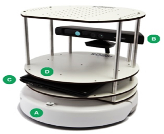
Turtlebot specifications.
3.2.2. Software specification
When the goal is to contribute to the development of cutting-edge autonomous navigation technologies, one works on a variety of software, beginning with the low-level "Robot Operating System" (ROS) and progressing up to the high level using different software packages like OpenCV and PCL.
3.2.2 Turtlebot brings up.
To start Turtlebot, one has to close the lid of Turtlebot's laptop, connect it via a USB cable, and run Turtlebot using the commands in Ubuntu 12.04. One can start the Kinect camera by plugging in the netbook's USB, as shown in Fig. 12(a) and (b). The detailed work will show in the next section.
Fig. 12.

(a) Turtlebot with connecting wires (b) Turtlebot and workstation Setup.
In this, one is going to discuss the instructions needed for the setting up of Turtlebot. The instructions depend on whether the individual prepared a USB-derived release, and one should export the variables inside the setup script. Fig. 13 displays the minimum nodes' flow diagrams. Driven wheels Located in the geographic center (x,y), the turtle bot on two front castor wheels is a disc with a radius . The definition of a Turtlebot is the collectively represented by equation (5).
| (5) |
Fig. 13.

Flowchart of Minimal Nodes in Turtlebot.
Fig. 12 shows a robot Turtlebot that is propelled by its two rear wheels and has two castor wheels in front. The wheelbase separates the radii of the two driving wheels at the back. The angle shown by the symbol depicts how the wheelchair robot is oriented about the the coordinate defines the axis of the cartesian plane . The center of the wheelchair robot may be found at the coordinates (x, y), which are situated at a distance of and an orientational angle of from the centers of the two wheels directly opposite at the rear of the device. The radial and angular velocities of the right and left rear wheels, respectively, are denoted by the variables and Respectively. To avoid collisions with moving and stationary objects, the Turtlebot robot is surrounded by the smallest feasible circle. Fig. 12 b depicts a circular safety zone around the Turtlebot robot, with its center at (x,y) and a radius of . So, the Turtlebot's setup vector looks like this:
| (6) |
Wheel radius and wheelbase kinematic characteristics have been considered to be perfectly known. The restrictions are obtained concerning (x,y) if the two rear wheels are assumed to be rolling without any lateral slip motion equation (6) and equation (7):
| (7) |
The derivations discovered in the body, as mentioned above in literature by Refs. [15,17], agree with this finding. Therefore, it can be said that this finding is consistent. These are the non-holonomic limitations that need to be adequately incorporated into the kinematic model of the wheelchair robot. These constraints apply to the wheelchair robot. The kinematic model of the robot about the location of its center, denoted by the notation , may be obtained as by equation (8):
| (8) |
The translational components of a wheelchair robot are the elements responsible for describing its location in a space with only two dimensions. Make it possible for the position of a wheelchair to be adjusted at the proper time be and orientational angle , with and as initial conditions. At , let Be the wheelchair robot's acceleration at any given point in time. As a result, we now have a system of ODEs:
assuming the initial conditions at as . Suppressing , we let and let . If the instantaneous velocity has a state feedback rule in the form by equation (9)
| (9) |
for some scalars, and some functions f(x(t)) and g(x(t)) to be adequately constructed later, and if we define G(x):=(-f(x),-g(x))R2, then the wheelchair robot is represented by for some scalars, and some functions to be created by equation (10)
| (10) |
The equation denotes the point of equilibrium for the wheelchair robot .
ROS serves as the backbone of the experimental setup, facilitating seamless communication between various components. It operates as a meta-operating system, comprising nodes, master nodes, and other components crucial for robot control.
In the context of the proposed algorithm, ROS becomes the orchestrator of the entire system. Most programming for robot movements in the specified environment is executed using Python and C++ within the ROS framework. The choice of ROS was supported by its compatibility with Ubuntu 12.04 and integration with the Microsoft Kinect camera, essential for perceiving the robot's path.
Nodes, fundamental processes in ROS, play a pivotal role in controlling the robot's wheels and collecting data from laser scanners and Kinect cameras. These nodes are responsible for acquiring images, performing localization, and executing path planning. The master node, roscore, functions akin to a DNS-like server, centralizing information and managing ROS nodes' data. The controller node stores critical information related to ROS nodes. ROS concepts such as topics and services, which are fundamental for communication between nodes. Topics facilitate information exchange, while services involve queries and responses between nodes, forming the basis of collaborative operations within system. A detailed depiction of the navigation system, as shown in Fig. 10, would further enhance clarity. This illustration should elucidate the interplay between high-level and low-level layers, elucidating how the robot executes tasks based on individual instructions. Moreover, discussing the creation of a 2-D grid map and the efficient computation of paths within the experimental pathways, as enabled by ROS functionalities, will accentuate the algorithm's prowess.By integrating these ROS-centric details, the manuscript will provide a more transparent and coherent narrative, ensuring that readers grasp the intricate relationship between the proposed algorithm and the ROS framework. This clarity is essential for a thorough comprehension of the experimental methodology and the algorithm's functionality.
3.2.3. Turtlebot creation
Before closing the lid of the TurtleBot laptop, please enter the following commands place the laptop/netbook on top of the TurtleBot and connect it with the USB cable. At Kobuki, you need to turn on your mobile base by pressing the power button, which looks like a switch on the left side of the device. As soon as the user switches it on, the LEDs flash eagerly.
Simultaneous Localization and Mapping (SLAM) is a core concept in robotics, addressing the dual challenge of locating a robot within an unknown environment while concurrently constructing a map of that environment. In autonomous navigation systems, SLAM plays a critical role in enabling robots to navigate and make informed decisions based on their surroundings. Techniques such as probabilistic approaches, graph optimization, and Bayesian filtering are commonly employed. Probabilistic frameworks, such as Extended Kalman Filters (EKF) or Particle Filters, enable the incorporation of uncertainty into the estimation process, enhancing the robustness of SLAM.
3.2.3.1. Graph-based SLAM
Graph-based SLAM is a prevalent optimization technique where the environment is represented as a graph, and nodes correspond to robot poses and landmarks. Edges in the graph capture the constraints between poses and observations. Through optimization algorithms like the Gauss-Newton method or Levenberg-Marquardt, the graph is refined to minimize errors and improve the accuracy of the map and robot localization.
3.2.3.2. Loop closure and global consistency
One crucial aspect of SLAM optimization is handling loop closures—instances where the robot revisits a previously traversed area. Managing loop closures ensures global consistency in the map. Techniques such as loop closure detection, place recognition, and loop closure corrections contribute to a more accurate and coherent representation of the environment.
3.2.3.3. Challenges and considerations
SLAM optimization is not without challenges. Computational complexity, real-time constraints, and the need for efficient data association are critical considerations. Balancing accuracy with computational efficiency is a continual challenge in SLAM research.
Incorporating this comprehensive section on SLAM optimization will provide readers with the necessary background to comprehend the algorithm's utilization of SLAM in autonomous navigation. This addition ensures that the manuscript is not only algorithm-centric but also educative, catering to a broader audience interested in the underlying principles of robotic navigation.
The novelty of SLAM optimization in comparison to state-of-the-art methods is crucial for emphasizing the contributions and advancements made in the proposed algorithm. Below is a detailed description focusing on the unique aspects and innovations that set SLAM optimization in this algorithm apart from existing methodologies:
3.2.3.4. Novelty of SLAM optimization in autonomous navigation
Integration of Intelligent Navigation System: The proposed SLAM optimization introduces a novel approach by seamlessly integrating an intelligent navigation system that relies solely on individual instructions. While traditional SLAM methods primarily focus on mapping and localization, this algorithm elevates the scope by incorporating real-time decision-making based on dynamic user input. This integration of an intelligent navigation system not only enhances the autonomy of the robot but also allows for adaptability to user preferences and on-the-fly adjustments to the navigation path.
Dynamic Path Perception using Rotating Kinect Sensor: A distinctive feature of the SLAM optimization is its utilization of a rotating Kinect sensor for dynamic path perception. Unlike conventional SLAM methods that may rely on static sensors, the rotating Kinect enables the algorithm to perceive the environment from various angles. This dynamic perception contributes to a more comprehensive and accurate mapping of the surroundings, particularly in scenarios with complex geometries or changing landscapes. The experimentation with various angles demonstrates the effectiveness of this approach, showcasing a novel dimension in SLAM optimization.
Efficient SLAM Problem Decomposition and Kalman Filter Implementation: The algorithm introduces an efficient decomposition of the SLAM problem into manageable components, coupled with the implementation of the Kalman filter on the experimental path. This strategic problem breakdown addresses localization and mapping challenges individually, allowing for a targeted and optimized solution. The Kalman filter, a widely used tool in control and estimation, is applied with a nuanced focus on considering both the system's knowledge and the measurement tool. This distinctive approach enhances the accuracy of the SLAM system state estimation, presenting a noteworthy advancement in the optimization of simultaneous localization and mapping.
Performance Evaluation on U-Shaped Experimental Pathway: The algorithm's performance evaluation on a U-shaped experimental pathway provides a practical benchmark for its novelty. The deviations measured at various angles, especially when navigating the Turtlebot in reverse, offer valuable insights into the algorithm's robustness and directional adaptability. This empirical validation sets the algorithm apart from conventional SLAM methods by demonstrating its efficacy in real-world scenarios, particularly in scenarios where deviations from the expected path may occur.
The proposed SLAM optimization introduces novel elements such as intelligent navigation integration, dynamic path perception, efficient problem decomposition, and a nuanced Kalman filter implementation. These unique aspects collectively contribute to the algorithm's advancement beyond state-of-the-art methods, enhancing the capabilities of autonomous navigation systems in dynamic and user-influenced environments.
3.2.3.5. Creation modes
There are three different ways of bringing up the turtlebot:
-
•
Minimal: this starts Turtlebot with various varieties via a single master ros environment where all processes can be started or stopped via ROS launchers. This Mode is used in this paper.
-
•
App Manager: it can do everything that minimal Mode does, but this Mode also allows handling one's programs as robot apps via the app manager like app chooser and develop.
-
•
Android Enabled: this Mode starts with private/public masters and permits a remote Android device to control the app manager.
3.2.3.6. Minimal Mode
-
•
Turtlebot navigates on an individual's instructions if one chooses the minimal Mode.
-
•
In this Mode, Turtlebot is placed on an experimental pathway; its parameters will be discussed.
-
•
The pathway is in U shape, which consists of 2 semicircular paths/turns, and at the time of navigation of turtlebot (forward direction), it faces two right turns between the starting and ending point of the experimental pathway, which is shown in fig, and while moving in reverse/backward direction, the turtlebot faces two left turns which are shown in Fig. 14.
-
•
Various tests are conducted on the experimental pathways while navigating the turtlebot on the individual's instructions. During the test, one must remember the parameters: starting point, I, turn, II, turn, and ending point.
-
•
The protector is used as a measuring device to evaluate different angles at various turns.
-
•
Comparisons of various angles and their deviations between forward navigation and reverse navigation of turtlebot like 150,300, 450,600,750,900,1050,1200, 1350,1500,1650,1800 were discussed later.
-
•
During the conduction of tests in minimal Mode, the position estimation of the turtlebot is done by odometry technique. Position estimation allows determining the location of the turtlebot at any time using infrared sensors.
-
•
Odometry techniques are widely used, and it is the least expensive in various cases; optical encoders are used to measure the rotation of the robot's wheel.
Fig. 14.

Kinect camera and odometry flowchart.
The formula for calculating the linear speed of the Turtlebot at the point in the center of its two driving wheels is as by equation (11):
| 11) |
Calculating the rotation speed at the center point of the wheelchair, which is located between the two driving wheels, requires equation (12):
| (12) |
where represents the length of the shaft that connects the two driving wheels, and stand for the left and right velocities of the driving wheels, and s represents the distance between the two driving wheels. To figure out the kinematic model of the chair equation (13) is used:
| (13) |
With x and y denote the speed of the wheelchair across the coordinates (x,y), and Where represents the angular velocity of the displacement.
A presentation of the dynamic modeling of the wheelchair is given by equation (14)-
| (14) |
Where represents the angle of the wheelchair's heel rest concerning the level of the ground and and stand for the left and right forces exerted by the driving wheels, respectively.
Here in Turtlebot, one uses a protector for measuring various angles in single or more tests, and for optical estimation Kalman filter is applicable.
These Fig. 15 and Fig. 16 were initially taken from the robotics research laboratory, giving a detailed view of the experimental path, including the starting point, ending point, first turn, and second turn.
Fig. 15.

An experimental path to turtlebot on it.
Fig. 16.

Path with turns I and II.
The core focus of this study is the experimental validation of a responsive robotic system, leveraging the sophisticated capabilities of the Turtlebot within the Robot Operating System (ROS) framework. The experimental design centers on precise navigation along a predefined trajectory in response to user instructions. The ROS ecosystem, characterized by its distributed architecture, is instrumental in orchestrating the myriad functionalities of the Turtlebot. The ROS nodes, predominantly scripted in Python and C++, serve as discrete processes, handling tasks such as wheel control, data acquisition from laser scanners and Kinect cameras, and intricate processes like localization and path planning.
In the proposed methodology, the kinematic model of the Turtlebot plays a pivotal role, enabling a nuanced understanding of its motion dynamics. Odometry techniques, integrating optical encoders to measure wheel rotations, facilitate real-time position estimation, forming the backbone for navigation experiments. Emphasizing the 'Minimal Mode' for Turtlebot navigation, the robot is strategically placed on a U-shaped experimental pathway. The trajectory includes pivotal turns, which become the focal points for comprehensive angle measurements using a specialized device known as a protector.
The study integrates advanced optical estimation techniques through the application of the Kalman filter. This sophisticated filter predicts the Turtlebot's motion based on hand location data obtained through repeated detection, contributing to enhanced accuracy in estimation. The experimental setup is augmented by dynamic modeling, where intricate equations governing forces, moments, and angles provide a holistic perspective on the robotic system's behavior.
An integral aspect of the methodology is the meticulous analysis of deviations in navigation performance between forward and reverse movements. This analysis is conducted at various angles ranging from 150 to 1800°, shedding light on the system's responsiveness to user instructions. The amalgamation of these technical elements positions the study at the forefront of robotic research, promising not only precise navigation but also insights into the nuanced interplay of sensors, algorithms, and actuators within the autonomous Turtlebot system.
4. Results and analysis
Twenty tests were run on the same path, which then compared the individual runs with the main experimental runs and an experienced turtlebot operator using the various inbuilt control systems. The tests were performed in a U-shaped pathway in the laboratory, and this pathway has two right turns containing difficult situations in daily life typical of modern office buildings and narrow doorways. In all tests, measures of performance were collected in the form of a dataset that is to be used as the basis of comparison: several sets, deviation at the starting point (mm), angles on the turn I (radian), angles on turn II (radian), deviation at the ending point (mm). Table 1 represents the experimental results of the diversion of turtlebot from the starting and ending point when it starts from the origin, and the graphical representation of the results is shown in Fig. 16.
Table 1.
Diversion of turtlebot at the starting and ending points.
| No of sets | Diversion of turtlebot concerning origin (starting point) | Diversion of turtlbot concerning origin (ending point) |
|---|---|---|
| 1 | 0 | 0 |
| 2 | 5 | 3 |
| 3 | 10 | 0 |
| 4 | 10 | 0 |
| 5 | 3 | 2 |
| 6 | 0 | 3 |
| 7 | 12 | 9 |
| 8 | 8 | 8 |
| 9 | 0 | 7 |
| 10 | 5 | 11 |
| 11 | 10 | 6 |
| 12 | 3 | 2 |
| 13 | 2 | 12 |
| 14 | 0 | 6 |
| 15 | 0 | 5 |
| 16 | 1 | 1 |
| 17 | 6 | 4 |
| 18 | 3 | 3 |
| 19 | 9 | 1 |
| 20 | 1 | 4 |
Parameters used.
-
•
Now one has to move the turtlebot on a particular path, which is 3 m long and 32 cm wide. It is chosen because it has two turns that are called semicircular paths.
-
•
An infrared projector and camera for the Kinect were separated by about 7.5 cm, while a color camera was around 2 cm distant.
-
•
When one places it on the experimental Route, the distance between the follower and the turtlebot is around 1.5 feet. The infrared pair can create a grid of distance measurements.
-
•
The projector was used to measure angles.
Table 1 shows the detour taken by the turtlebot at the outset, with the distance traveled from that point to the beginning of the curve (i.e., turn I) estimated. Then the distance traveled from the end of the curve (turn II) to the end of the U-shaped experimental pathway estimated once more.
One can observe that the deviation is not very significant at the beginning and finishing points by looking at Fig. 17, Fig. 18. This is because the experimental Route is linear, which can be mathematically shown by taking the complete set and computing the standard deviation, which comes out to around 5.326 mm. In addition, one can see this by looking at Fig. 17, Fig. 18. However, this is not when the turtlebot makes a right turn at Turn I and Turn II; thus, one may estimate various reflexive angles when it rotates; hence; the table contains data obtained via experimentation.
Fig. 17.

Turtlebot diversion at the starting point.
Fig. 18.

Turtlebot diversion at the ending point.
Table 2: depicts the detailed representation of the experimental work that one takes during the navigation (right turn) of turtlebot, which is based on the individual's instructions. The angles were measured using a protector as one of the measuring devices used in this paper.
Table 2.
Turtlebot's right Turn I and Turn II angles.
| No of sets | 150 | 300 | 450 | 600 | 750 | 900 | 1050 | 1200 | 1350 | 1500 | 1650 | 1800 |
|---|---|---|---|---|---|---|---|---|---|---|---|---|
| 1 | 5 | 15 | 30 | 42 | 47 | 49 | 45 | 41 | 31 | 15 | 6 | 0 |
| 2 | 8 | 16 | 30 | 43 | 49 | 51 | 49 | 42 | 30 | 15 | 8 | 0 |
| 3 | 6 | 15 | 32 | 42 | 56 | 56 | 58 | 43 | 32 | 16 | 5 | 1 |
| 4 | 7 | 18 | 31 | 45 | 60 | 62 | 62 | 44 | 31 | 18 | 7 | 0 |
| 5 | 5 | 16 | 35 | 44 | 61 | 63 | 63 | 45 | 36 | 17 | 6 | 2 |
| 6 | 9 | 17 | 34 | 44 | 62 | 64 | 64 | 43 | 34 | 16 | 9 | 0 |
| 7 | 6 | 15 | 31 | 45 | 56 | 57 | 58 | 45 | 35 | 15 | 6 | 3 |
| 8 | 7 | 19 | 33 | 47 | 57 | 59 | 59 | 47 | 33 | 17 | 7 | 4 |
| 9 | 6 | 16 | 35 | 46 | 64 | 66 | 66 | 50 | 35 | 19 | 5 | 0 |
| 10 | 7 | 18 | 37 | 49 | 58 | 60 | 59 | 49 | 37 | 18 | 5 | 5 |
| 11 | 8 | 19 | 39 | 52 | 62 | 62 | 60 | 46 | 39 | 16 | 8 | 0 |
| 12 | 9 | 20 | 37 | 51 | 60 | 60 | 58 | 48 | 38 | 20 | 9 | 4 |
| 13 | 6 | 16 | 39 | 52 | 67 | 69 | 65 | 52 | 39 | 18 | 8 | 3 |
| 14 | 10 | 16 | 40 | 49 | 63 | 64 | 61 | 49 | 40 | 16 | 10 | 2 |
| 15 | 5 | 17 | 38 | 52 | 68 | 68 | 66 | 52 | 37 | 17 | 9 | 4 |
| 16 | 8 | 19 | 35 | 50 | 70 | 72 | 67 | 50 | 35 | 19 | 8 | 1 |
| 17 | 6 | 15 | 34 | 51 | 68 | 70 | 64 | 51 | 34 | 18 | 6 | 2 |
| 18 | 10 | 16 | 38 | 48 | 68 | 69 | 63 | 48 | 38 | 16 | 5 | 0 |
| 19 | 9 | 18 | 31 | 50 | 70 | 71 | 68 | 50 | 31 | 15 | 9 | 0 |
| 20 | 10 | 20 | 32 | 46 | 71 | 71 | 65 | 47 | 32 | 20 | 10 | 1 |
Here, from the above, Fig. 19 and Fig. 20 analyses of our turtle bot were done, and one can say that there is an increment and decrement of diversion after angle 900 during the right turn.
Fig. 19.

Turtlebot reflexive angle right Turn I.
Fig. 20.

Turtlebot reflexive angles, right Turn II.
Table 3 depicts the detailed representation of the experimental work that one takes during the navigation (left turn) of Turtlebot, which is based on the individual's instructions. The angles were measured using a protector as one of the measuring devices used in this paper.
Table 3.
Turtlebot's left Turn I and Turn II angles.
| No of sets | 150 | 300 | 450 | 600 | 750 | 900 | 1050 | 1200 | 1350 | 1500 | 1650 | 1800 |
|---|---|---|---|---|---|---|---|---|---|---|---|---|
| 1 | 7 | 17 | 32 | 43 | 54 | 58 | 49 | 44 | 31 | 16 | 6 | 0 |
| 2 | 8 | 17 | 33 | 44 | 56 | 62 | 53 | 43 | 31 | 16 | 8 | 0 |
| 3 | 6 | 18 | 32 | 43 | 60 | 67 | 58 | 44 | 32 | 15 | 7 | 1 |
| 4 | 7 | 18 | 35 | 44 | 61 | 67 | 60 | 45 | 33 | 19 | 7 | 0 |
| 5 | 8 | 17 | 37 | 48 | 60 | 63 | 61 | 46 | 35 | 18 | 6 | 1 |
| 6 | 9 | 19 | 36 | 45 | 62 | 64 | 62 | 44 | 34 | 17 | 9 | 0 |
| 7 | 6 | 18 | 35 | 45 | 59 | 59 | 58 | 45 | 36 | 15 | 6 | 3 |
| 8 | 7 | 17 | 34 | 49 | 58 | 64 | 57 | 49 | 33 | 20 | 8 | 3 |
| 9 | 5 | 19 | 35 | 53 | 60 | 66 | 59 | 46 | 35 | 17 | 6 | 0 |
| 10 | 6 | 18 | 37 | 51 | 61 | 65 | 58 | 49 | 37 | 19 | 7 | 5 |
| 11 | 8 | 20 | 40 | 49 | 60 | 61 | 62 | 52 | 41 | 20 | 8 | 0 |
| 12 | 9 | 20 | 38 | 48 | 58 | 66 | 64 | 51 | 37 | 21 | 10 | 4 |
| 13 | 8 | 18 | 39 | 52 | 58 | 69 | 67 | 52 | 39 | 16 | 7 | 3 |
| 14 | 10 | 18 | 42 | 49 | 61 | 64 | 63 | 51 | 42 | 16 | 10 | 2 |
| 15 | 9 | 17 | 39 | 52 | 63 | 68 | 68 | 52 | 38 | 17 | 6 | 4 |
| 16 | 8 | 21 | 35 | 50 | 62 | 70 | 65 | 50 | 37 | 20 | 8 | 2 |
| 17 | 7 | 20 | 34 | 51 | 64 | 70 | 68 | 51 | 34 | 16 | 7 | 1 |
| 18 | 6 | 19 | 38 | 53 | 60 | 69 | 68 | 50 | 38 | 16 | 10 | 0 |
| 19 | 9 | 18 | 33 | 52 | 63 | 71 | 66 | 50 | 32 | 19 | 9 | 0 |
| 20 | 10 | 22 | 34 | 49 | 65 | 71 | 65 | 48 | 33 | 20 | 10 | 1 |
Hence, from the above, Fig. 21, Fig. 22 analyses of turtlebot were done, and one can say that there is an increment and decrement of diversion after angle 900 if turtlebot turns left. The comparison of forwarding and reverse navigation of turtlebot at various angles is shown in Table 4.
Fig. 21.

Turtlebot reflexive angle left Turn I.
Fig. 22.

Turtlebot reflexive angle left Turn II.
Table 4.
Comparison of forwarding and reverse navigation of turtlebot.
| Angles | 150 | 300 | 450 | 600 | 750 | 900 | 1050 | 1200 | 1350 | 1500 | 1650 | 1800 |
|---|---|---|---|---|---|---|---|---|---|---|---|---|
| Standard Deviation | 1.681 | 1.657 | 3.169 | 3.352 | 6.567 | 6.428 | 5.612 | 3.269 | 3.004 | 1.596 | 1.67 | 1.65 |
Hence, it is proved mathematically that the diversions or standard deviation increase to 900 in the right turn of turtlebot and decrease after that.
The proposed algorithm for autonomous navigation of the Turtlebot stands as a noteworthy contribution to the field of robot control, particularly in enhancing the precision and adaptability of robotic systems. To establish its significance and validate the author's claims, a comprehensive comparative analysis with existing robot control algorithms is integral. This multifaceted analysis encompasses a range of aspects, from defining performance metrics to conducting diverse experiments and employing statistical rigor.
Firstly, a meticulous selection of performance metrics is crucial, as they act as the quantifiable benchmarks for evaluating the proposed algorithm's efficiency. These metrics could include navigation accuracy, speed, adaptability to dynamic environments, and resource utilization. The algorithm's ability to perform well across these parameters serves as a key indicator of its overall efficacy.
The experimental setup plays a pivotal role in substantiating the algorithm's claims. Rigorous testing in diverse scenarios, including environments with obstacles, varying light conditions, and complex terrains, provides a holistic evaluation. The response of the Turtlebot to dynamic scenarios, such as abrupt changes in user instructions or environmental disturbances, should be examined to gauge the algorithm's robustness shown in Table 5.
Table 5.
Comparison between right turn angle (above) and left turn angles (below) in mm.
| Angles | 150 | 300 | 450 | 600 | 750 | 900 | 1050 | 1200 | 1350 | 1500 | 1650 | 1800 |
|---|---|---|---|---|---|---|---|---|---|---|---|---|
| Standard Deviation | 1.388 | 1.395 | 2.70 | 3.35 | 2.58 | 3.74 | 5.023 | 3.060 | 3.101 | 1.87 | 1.44 | 1.59 |
In selecting comparative algorithms, a judicious choice spanning classical control theory, machine learning, and other contemporary approaches ensures a comprehensive evaluation. The algorithm should be benchmarked against these counterparts to ascertain its relative strengths and weaknesses. Quantitative analysis, using metrics such as path planning efficiency and computational requirements, facilitates an objective and data-driven comparison.
Qualitative aspects, including user-friendliness, real-time adaptability, and ease of implementation, provide additional dimensions to the comparative analysis. Soliciting feedback from users and expert's aids in understanding the practical utility and acceptance of the proposed algorithm in real-world scenarios.
Robustness testing is imperative to evaluate how well the algorithm performs under stress tests and edge cases. Assessing its behavior in scenarios where sensor data is noisy or incomplete contributes to a comprehensive understanding of its limitations and capabilities.
Statistical significance adds a layer of validation to the comparative analysis, ensuring that observed differences between the proposed algorithm and others are not mere chance. Appropriate statistical tests enhance the credibility of the findings.
Finally, visualization through trajectory plots, obstacle avoidance maneuvers, and real-time mapping provides a tangible representation of the algorithm's performance. These visual aids not only aid in conveying the algorithm's behavior but also enhance the interpretability of results for a broader audience.
Thorough comparative analysis incorporating these elements will serve to validate the proposed algorithm's efficacy, substantiate the author's claims, and contribute substantively to the advancement of robot control algorithms shown in Table 6.
Table 6.
Comparative analysis of Existing and proposed System with different parameters.
| Feature and Hardware Specifications | TurtleBot [23] | Roomba [28] | ROS Navigation Stack [29] | Clearpath Jackal [30] | DJI RoboMaster S1 [31] | Proposed System |
|---|---|---|---|---|---|---|
| Sensors | LIDAR, Camera | Cliff sensor, LIDAR, Camera | LIDAR, Camera | LIDAR, Camera, IMU | Vision, Ultrasonic, Infrared | LIDAR, Ultrasonic, Infrared |
| Processing Power | Moderate | Limited | High | High | High | High |
| Battery Life | Moderate | Limited | N/A | Long-lasting | Moderate | Moderate |
| Mobility | Differential drive | Differential drive | Differential drive | Differential drive | Omni wheels | Differential drive |
| Navigation Algorithms | SLAM, AMCL, Navigation | Roomba proprietary | AMCL, DWA Planner | SLAM, AMCL, Navigation | Visual SLAM, Visual Navigation | SLAM, AMCL, Navigation |
| Path Planning | DWA Planner | Proprietary | DWA Planner | DWA Planner | Proprietary | DWA Planner |
| Obstacle Avoidance | Yes | Yes | Yes | Yes | Yes | Yes |
| Localization Accuracy | Moderate | Moderate | High | High | High | High |
However, the left turn of Turtlebot increases till 1050 as the readings or data are approximately the same in the cases of 750 and 1050, which is approximately 5%–6% more than that of the right turn.
The proposed algorithm for autonomous navigation in wheelchairs presents distinct advantages compared to other robot control algorithms. One notable strength lies in its exceptional flexibility and adaptability. Unlike conventional algorithms that may necessitate predefined structures, this algorithm operates effectively based on individual instructions, allowing for seamless navigation in dynamic and evolving environments. This adaptability is a crucial feature, especially in real-world scenarios where environmental conditions may change unpredictably.
A significant edge of the proposed algorithm is its integration of Simultaneous Localization and Mapping (SLAM) techniques in real-time. The algorithm not only builds a 2-D grid map during navigation but also localizes the wheelchair within this map. This simultaneous mapping and localization enhance spatial awareness, enabling precise and context-aware navigation. This feature distinguishes the algorithm from others, particularly those that may rely on pre-existing maps or struggle with real-time adjustments.
The algorithm showcases efficiency in computing optimal paths to user-specified destinations within experimental pathways. Its ability to navigate without the need for predefined structures sets it apart, offering adaptability as individuals deviate from marked paths. This characteristic is crucial for scenarios where users may require non-linear or personalized routes. The proposed algorithm's advantages lie in its adaptability, real-time SLAM integration, and efficiency in computing optimal paths. These features position the algorithm as a promising solution for autonomous navigation in wheelchairs, demonstrating a notable advancement in the field of robot control algorithms.
5. Conclusions
In this paper, we have outlines an autonomous navigation system designed for a wheelchair, driven by individual instructions, and experimentally validated on a U-shaped pathway. Throughout the experimentation, the system demonstrated key capabilities such as the creation of a 2-D grid map using simultaneous localization and mapping (SLAM) techniques in real-time. This map-building process, integrated with SLAM, ensures that the wheelchair can navigate the U-shaped path autonomously while adapting to changes in the environment.
A significant aspect of the system is its capacity to compute efficient paths to user-specified destinations within the experimental pathways. Notably, it operates without the need for predefined structures, allowing for adaptability as individuals deviate from marked paths.
To address the SLAM problem, the study breaks it down into components and implements the Kalman filter on the experimental path. The Kalman filter, a mathematical process, optimally estimates the system's state by considering information from within the system and the measuring instrument. Specifically, it focuses on challenges related to localization and mapping, leveraging data from actuators, vehicle position, robot movement sensors, and sensor readings representing the world state.
The utilization of various standard and modern open-source software packages in the development of the Turtlebot, the experimental device in this study, holds promise for future wheelchair navigation research. The platform not only serves as a tool for experimentation but also lays the groundwork for Dynamic Control's prospective endeavors in wheelchair navigation.
In light of the experimental findings, it is observed that when the Turtlebot navigates in the reverse direction, there is a 5%–6% increase in diversion compared to forward navigation. This observation offers valuable insights for refining the navigation algorithm, shedding light on potential areas for improvement. In conclusion, while the manuscript lacks clarity in certain aspects, the presented autonomous navigation system, with its adaptable and SLAM-enabled features, represents a noteworthy contribution to the field, paving the way for advancements in intelligent wheelchair navigation. As limitation of this work is The proposed algorithm's reliance on sensor accuracy poses a limitation, as inaccuracies or environmental factors may affect performance. Additionally, the algorithm's adaptability makes it sensitive to rapid environmental changes, potentially impacting its effectiveness in dynamic scenarios. These considerations highlight areas for refinement to enhance the algorithm's robustness.
Data availability
The data employed in this investigation is made readily available on the request from the first author.
CRediT authorship contribution statement
Ankit Kumar: Writing – review & editing, Writing – original draft, Validation, Methodology, Investigation, Formal analysis, Data curation, Conceptualization. Kamred Udham Singh: Validation, Software, Formal analysis, Data curation, Conceptualization. Pankaj Dadheech: Writing – original draft, Validation, Software, Resources, Methodology, Investigation, Formal analysis, Data curation. Aditi Sharma: Writing – review & editing, Visualization, Validation, Software, Resources, Investigation, Funding acquisition, Formal analysis. Ahmed I. Alutaibi: Writing – review & editing, Visualization, Validation, Software, Resources, Project administration, Methodology, Funding acquisition, Formal analysis, Data curation. Ahed Abugabah: Writing – original draft, Visualization, Validation, Software, Resources, Project administration, Methodology, Investigation, Funding acquisition, Formal analysis. Arwa Mohsen Alawajy: Writing – review & editing, Visualization, Validation, Resources, Project administration, Methodology, Investigation, Funding acquisition, Formal analysis.
Declaration of competing interest
The authors declare that they have no known competing financial interests or personal relationships that could have appeared to influence the work reported in this paper.
Acknowledgment
The author extends the appreciation to the Deanship of Postgraduate Studies and Scientific Research at Majmaah University for funding this research work through the project number (R-2024-976).
Contributor Information
Ankit Kumar, Email: iiita.ankit@gmail.com.
Kamred Udham Singh, Email: 11004033@gs.ncku.edu.tw.
Pankaj Dadheech, Email: pankajdadheech777@gmail.com.
Aditi Sharma, Email: aditi.sharma@ieee.org.
Ahmed I. Alutaibi, Email: a.alutaibi@mu.edu.sa.
Ahed Abugabah, Email: ahed.abugabah@zu.ac.ae.
Arwa Mohsen Alawajy, Email: alawajy@ksu.edu.sa.
References
- 1.Almansouri A.S., Upadhyaya L., Nunes S.P., Salama K.N., Kosel J. "An assistive magnetic skin system: enabling technology for quadriplegics." article. Adv. Eng. Mater. Jan 2021;23(1) doi: 10.1002/adem.202000944. [DOI] [Google Scholar]
- 2.Amer S.G., Kamh S.A., Elshahed M.A., Ramadan R.A. "Wheelchair control system based eye gaze." article. Int. J. Adv. Comput. Sci. Appl. Jun 2021;12(6):889–894. [Google Scholar]
- 3.Bakouri M., Alsehaimi M., Ismail H.F., Alshareef K., Ganoun A., Alqahtani A., Alharbi Y. Steering a robotic wheelchair based on voice recognition system using convolutional neural networks. Article. Electronics. Jan 2022;11(1) doi: 10.3390/electronics11010168. [DOI] [Google Scholar]
- 4.Basurto D., Sananes N., Verbeken E., Sharma D., Corno E., Valenzuela I., van der Veeken L., et al. New device permitting non-invasive reversal of fetal endoscopic tracheal occlusion:ex-vivoandin-vivostudy. Ultrasound Obstet. Gynecol. Oct 2020;56(4):522–530. doi: 10.1002/uog.22132. Article. [DOI] [PubMed] [Google Scholar]
- 5.Belkacem A.N., Jamil N., Palmer J.A., Ouhbi S., Chen C. Brain-computer interfaces for improving the quality of life of older adults and elderly patients. Review. Front. Neurosci. Jun 2020;14:692. doi: 10.3389/fnins.2020.00692. [DOI] [PMC free article] [PubMed] [Google Scholar]
- 6.Bellal S.E., Mouss L.H., Sahnoun M., Messaadia M. User behaviour-based approach to define mobility devices needs of disabled person in Algeria: a questionnaire study. Article. Disability and Rehabilitation-Assistive Technology. May 2022;17(4):453–461. doi: 10.1080/17483107.2020.1791263. [DOI] [PubMed] [Google Scholar]
- 7.Bhat S.A., Dar M.A., Elalfy H., Matheen M.A., Shah S. "A novel framework for modelling wheelchairs under the realm of internet-of-things." article. Int. J. Adv. Comput. Sci. Appl. Feb 2021;12(2):745–751. [Google Scholar]
- 8.Bouafif L., Ellouze N. Implementation of a biometric interface in voice controlled wheelchairs. Article. Sound and Vibration. 2020;54(1):1–15. doi: 10.32604/sv.2020.08665. [DOI] [Google Scholar]
- 9.Chatterjee S., Roy S. A low-cost assistive wheelchair for handicapped & elderly people. Article. Ain Shams Engineering Journal. Dec 2021;12(4):3835–3841. doi: 10.1016/j.asej.2021.04.021. [DOI] [Google Scholar]
- 10.Chen T., Wu H.C. Assessing the suitability of smart technology applications for E-health using a judgment-decomposition analytic hierarchy process approach. Article. Health and Technology. May 2020;10(3):767–776. doi: 10.1007/s12553-020-00408-7. [DOI] [Google Scholar]
- 11.Chenier F., Pelland-Leblanc J.P., Parrinello A., Marquis E., Rancourt D. "A high sample rate, wireless instrumented wheel for measuring 3d pushrim kinetics of a racing wheelchair." article. Med. Eng. Phys. Jan 2021;87:30–37. doi: 10.1016/j.medengphy.2020.11.008. [DOI] [PubMed] [Google Scholar]
- 12.Chikh S., Boudet S., Pinti A., Garnier C., El Hage R., Azaiez F., Watelain E. "Predicting manual wheelchair initiation movement with emg activity during over ground propulsion." article. Journal of Spinal Cord Medicine. Mar 2022;45(2):262–269. doi: 10.1080/10790268.2020.1778352.<GotoISI>://WOS:000547984000001. [DOI] [PMC free article] [PubMed] [Google Scholar]
- 13.Cojocaru D., Manta L.F., Pana C.F., Dragomir A., Mariniuc A.M., Vladu I.C. The design of an intelligent robotic wheelchair supporting people with special needs, including for their visual system. Article. Healthcare. Jan 2022;10(1) doi: 10.3390/healthcare10010013. [DOI] [PMC free article] [PubMed] [Google Scholar]
- 14.Fung K.R., Miller T., Rushton P.W., Goldberg M., Toro M.L., Seymour N., J Pearlman, and professionals int soc wheelchair. "Integration of wheelchair service provision education: current situation, facilitators and barriers for academic rehabilitation programs worldwide." article. Disabil. Rehabil. Assist. Technol. Jul 2020;15(5):553–562. doi: 10.1080/17483107.2019.1594408. [DOI] [PubMed] [Google Scholar]
- 15.Gawande M., Wang P., Arnold G., Nasir S., Abboud R., Wang W.J. Effect of wheelchair configurations on shoulder movements, push rim kinetics and upper limb kinematics while negotiating a speed bump. Article. Ergonomics. Jul 2022;65(7):987–998. doi: 10.1080/00140139.2021.2008018. [DOI] [PubMed] [Google Scholar]
- 16.Jaffery M.H., Ashraf M.A., Almogren A., Asim H.M., Arshad J., Khan J., Rehman A.U., Hussen S. Fsr-based smart system for detection of wheelchair sitting postures using machine learning algorithms and techniques. J. Sens. May 2022;2022 doi: 10.1155/2022/1901058. Article. [DOI] [Google Scholar]
- 17.Khan M.M., Safa S.N., Ashik M.H., Masud M., AlZain M.A. Research and development of a brain-controlled wheelchair for paralyzed patients. Article. Intelligent Automation and Soft Computing. 2021;30(1):49–64. doi: 10.32604/iasc.2021.016077. [DOI] [Google Scholar]
- 18.Kumtepe E.D., Corbacioglu E., Basoglu A.N., Daim T.U., Shaygan A. Design based exploration of medical system adoption: case of wheelchair ramps. Article. Technology in Society. Aug 2021;66 doi: 10.1016/j.techsoc.2021.101620. [DOI] [Google Scholar]
- 19.Lecrosnier L., Khemmar R., Ragot N., Decoux B., Rossi R., Kefi N., Ertaud J.Y. Deep learning-based object detection, localisation and tracking for smart wheelchair healthcare mobility. Article. International Journal of Environmental Research and Public Health. Jan 2021;18(1):91. doi: 10.3390/ijerph18010091. [DOI] [PMC free article] [PubMed] [Google Scholar]
- 20.Ma C.C., Du J., Gravina R. Abnormal behavior detection based on activity level using fuzzy inference system for wheelchair users. Article. Human-Centric Computing and Information Sciences. May 2022;12 doi: 10.22967/hcis.2022.12.021. [DOI] [Google Scholar]
- 21.Marques L.S., Magalhaes R.R., de Lima D.A., Tsuchida J.E., Fuzatto D.C. Virtual environment for smart wheelchair simulation. Ieee Latin America Transactions. Mar 2021;19(3):456–465. doi: 10.1109/tla.2021.9447695. Article. [DOI] [Google Scholar]
- 22.Meng Q.L., Jiang M.P., Jiao Z.Q., Yu H.L. Bionic design and analysis of a multi-posture wheelchair. Article. Mechanical Sciences. Jan 2022;13(1):1–13. doi: 10.5194/ms-13-1-2022. [DOI] [Google Scholar]
- 23.Mousa G., Almaddah A., Aly A.A. Design and implementation of wheel chair control system using Particle swarm algorithm. Cmc-Computers Materials & Continua. 2021;66(2):2005–2023. doi: 10.32604/cmc.2020.012580. Article. [DOI] [Google Scholar]
- 24.Paing M.P., Juhong A., Pintavirooj C. Design and development of an assistive system based on eye tracking. Article. Electronics. Feb 2022;11(4) doi: 10.3390/electronics11040535. [DOI] [Google Scholar]
- 25.Ryu H.Y., Kwon J.S., Lim J.H., Kim A.H., Baek S.J., Kim J.W. Development of an autonomous driving smart wheelchair for the physically weak. Article. Applied Sciences-Basel. Jan 2022;12(1) doi: 10.3390/app12010377. [DOI] [Google Scholar]
- 26.Teeneti C., Pratik U., Philips G., Azad A., Greig M., Zane R., Bodine C., Coopmans C., Pantic Z. System-level approach to designing a smart wireless charging system for power wheelchairs. Article. Ieee Transactions on Industry Applications. Sep 2021;57(5):5128–5144. doi: 10.1109/tia.2021.3093843. [DOI] [Google Scholar]
- 27.Telles M.J., Santos R., da Silva J.M., Righi R.D., Barbosa J.L.V. "An intelligent model to assist people with disabilities in smart cities." article. J. Ambient Intell. Smart Environ. 2021;13(4):301–324. doi: 10.3233/ais-210606. [DOI] [Google Scholar]
- 28.Utaminingrum F., Pangestu G., Syauqy D., Sari Y.A., Shih T.K. "Detecting of eyeball movements for choosing menu in display monitor using height and sector percentage measurement approaches." article. Multimed. Tool. Appl. Aug 2021;80(19):29827–29848. doi: 10.1007/s11042-021-10887-z. [DOI] [Google Scholar]
- 29.Woo J., Yamaguchi K., Ohyama Y. "Development of a control system and interface design based on an electric wheelchair." article. J. Adv. Comput. Intell. Intell. Inf. Sep 2021;22(5):655–663. doi: 10.20965/jaciii.2021.p0655. [DOI] [Google Scholar]
- 30.Zhang B.Q., Amirian J., Eberle H., Pettre J., Holloway C., Carlson T. "From hri to cri: crowd robot interaction-understanding the effect of robots on crowd motion empirical study of pedestrian dynamics with a wheelchair and a pepper robot." article. Int. J. Soc. Robotics. Apr 2022;14(3):631–643. doi: 10.1007/s12369-021-00812-7. [DOI] [Google Scholar]
- 31.Zhou X.J., Ruhaizin S., Zhu W., Shen C., He X.B. Application of neuroengineering based on eeg features in the industrial design of comfort. Article. Computational Intelligence and Neuroscience. Jun 2022;2022 doi: 10.1155/2022/4667689. [DOI] [PMC free article] [PubMed] [Google Scholar] [Retracted]
- 32.Jamwal Prashant K., Niyetkaliyev Aibek, Hussain Shahid, Sharma Aditi, Paulette Van Vliet Utilizing the intelligence edge framework for robotic upper limb rehabilitation in home. MethodsX. 2023;11 doi: 10.1016/j.mex.2023.102312. ISSN 2215-0161. [DOI] [PMC free article] [PubMed] [Google Scholar]
Associated Data
This section collects any data citations, data availability statements, or supplementary materials included in this article.
Data Availability Statement
The data employed in this investigation is made readily available on the request from the first author.