Abstract
This paper presents a deep-learning-based workflow to detect synapses and predict their neurotransmitter type in the primitive chordate Ciona intestinalis (Ciona) electron microscopic (EM) images. Identifying synapses from EM images to build a full map of connections between neurons is a labor-intensive process and requires significant domain expertise. Automation of synapse classification would hasten the generation and analysis of connectomes. Furthermore, inferences concerning neuron type and function from synapse features are in many cases difficult to make. Finding the connection between synapse structure and function is an important step in fully understanding a connectome. Class Activation Maps derived from the convolutional neural network provide insights on important features of synapses based on cell type and function. The main contribution of this work is in the differentiation of synapses by neurotransmitter type through the structural information in their EM images. This enables the prediction of neurotransmitter types for neurons in Ciona, which were previously unknown. The prediction model with code is available on GitHub.
Keywords: Ciona, computer vision, electron microscopy
Impact Statement
The working of a brain is an emergent property of the attributes and connectivity of its constitutive parts—the neurons. The field of connectomics seeks to describe these features on a nervous systemwide scale, because only then can the researcher conceptualize, model, and manipulate complete neural circuits driving behavior. Experimentally describing the enormous number of synaptic connections within a nervous system in detail is a daunting task, and is limited by the current technology to animals with small nervous systems. One such animal is the primitive Chordate Ciona. The Ciona connectome, which was derived by serial-section electron microscopy (EM), describes the 177 neurons, and 6,618 synapses, that make up the central nervous system of a Ciona larva. While the resulting EM-derived connectivity matrix isely essential starting point for circuit analysis, it does not readily reveal essential properties of the neurons, such as excitatory, inhibitory, or modulatory synaptic connections. The goal of the current work is to determine if neurotransmitter types can be distinguished through structural information in synaptic EM images. This enables the prediction of neurotransmitter types for neurons in Ciona, which were previously unknown, and paves a way for streamlined annotation of EM images of synapses.
1. Introduction
We propose a deep-learning, convolutional neural network to detect Ciona intestinalis (Ciona) synapses via image patch classification from serial-section-transmission electron microscopic (EM) images, as well as a multimodal method of predicting neurotransmitter type based on several modalities of data obtained in different ways—EM imaging, light microscopy of in situ hybridization, and behavioral observation experiments. Ciona is of interest to neuroscientists because of its close evolutionary relationship to vertebrates and small nervous system. Moreover, it is one of the very few animals for which a complete synaptic connectome is available(1). An essential aspect of constructing a connectome, a comprehensive map of neurons and their connections in the brain, is to identify the synapses that form chemical and electrical communication links between neurons(2). Traditionally, the classification of synapses is completed manually through expert analysis of thousands of images. This is a time-consuming process that can take thousands of hours for one specimen. For example, the first Ciona connectome was constructed manually over a period of 5 years from serial-section EM images(1). Another crucial but missing component of understanding the connectome is the classification of the function and properties of each synapse. One of the most important properties is neurotransmitter use. While some experimental methods, such as in situ hybridization, can identify cells, or clusters of cells, expressing transcripts indicating neurotransmitter use(3), the resolving power of light microscopy cannot reveal the connectivity of these neurons. Additionally, in cases with intermingled neurotransmitter types and high variability in neuron location across specimens, it may not be possible to find correspondence between neuron properties derived by in situ hybridization and neurons identified by serial EM in the course of constructing the connectome. Visual inspection of the synapses in Ciona EM images does not reveal any distinguishable differences between known excitatory and inhibitory neurons. Some examples are included in Figure 1. Like all chemical synapses, those in Ciona include the vesicle cluster in the presynaptic neuron, which varies in count and size, and the postsynaptic density, which also varies in size and density. No apparent pattern in these features is visible upon manual inspection.
Figure 1.
Examples of (a) inhibitory and (b) excitatory synapses. The synaptic region is circled in green. It can be seen that there are varying vesicle counts and sizes, as well as little visible postsynaptic density.
In this paper, We define “Synapse Classification” to mean the classification of whether an image patch contains a synapse or not. We define “Neurotransmitter-Type Prediction” to mean the prediction of neurotransmitter type in an image patch already assumed to contain a synapse. We use manually annotated EM images of a Ciona larva to validate our findings. We also propose a deep-learning method to predict the neurotransmitter type of a neuron based on the appearance of its synapses in EM images, and generate Class Activation Maps(4) from the prediction model to visualize the features that are important in synapse neurotransmitter-type prediction.
1.1. Contributions
Our main contributions are as follows.
An automated method to detect and localize synapses from EM data with high accuracy.
A method to predict the neurotransmitter class of neurons in Ciona based on its synapse structure. Creation and analysis of class activation maps based on grad-CAM(4) from the neural network to derive the synaptic features that are identified as important to neurotransmitter-type prediction.
Model-based predictions of neurotransmitter class by cell, which are previously unknown, and can be used in further experiments to help determine the true neurotransmitter expression of said cells.
The methods and data are available upon request.
2. Prior Work
Previous work have reported successful application of computer vision methods for automatically detecting synapses in EM images of Drosophila, mouse, and rabbit neurons(5–9). However, the synapses of these organisms contain unique features, which the systems rely on heavily. The algorithm for Drosophila synapse detection(5,8,9) involves the distinctive t-shaped feature and postsynaptic density to detect the synapse, often with a 3D U-Net-inspired network(10), while the algorithms for mouse synapse detection(6,7) were created for cryogenic EM. One approach applies pixel-level classification and graph cut segmentation on EM images to identify potential synapses, then filters the potential synapses with a random forest classifier(6). The classifiers are trained on manually annotated samples. A second approach finds handcrafted synaptic cleft features for the presynaptic and postsynaptic region, and uses LogitBoost to perform the final synapse detection(7). A third publication describes the uses of a fusion of ribbon, cleft, and vesicle features of a rabbit retina synapse to detect retinal synapses through kernel learning(11). Ribbons are not ubiquitous among synapses, and clefts are not always visible for different types of synapses, so this method would not work on all types of synapses.
Studies have qualitatively shown differences between excitatory and inhibitory synapses—namely that the vesicle shape and postsynaptic density appearance varied between the two functions(12–14). However, these papers are mostly qualitative and do not provide predictive functionality. Furthermore, these studies do not analyze a large number of synapses, and are not directly translatable to Ciona synapses due to differences between species. More recently, synapse neurotransmitter-type prediction using a deep network was done on EM images of Drosophila neurons(15). This body of work is most similar to the one presented in this paper, but the appearance of Drosophila synapses differs drastically from those of Ciona. Our previous study(3) combined in situ hybridization with the existing connectome derived from EM to determine the neurotransmitter expression of neuron types, such as the photoreceptors. Point cloud matching was done to match relative cell locations in three dimensions between fluorescent microscopic and EM results. While we are successful in determining the neurotransmitter expression of individual cells belonging to the photoreceptors, we are unable to determine with certainty the neurotransmitter expression of individual cells belonging to the relay neurons (RNs) and other types. The present study aims to take steps toward resolving the neurotransmitter assignments in these ambiguous regions while applying neural network approaches to this problem.
3. Data
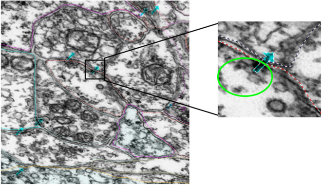
The data consisted of EM images from a total of 3,375 60-nm serial sections from the anterior brain vesicle to the motor ganglion of a Ciona larva. The sections were collected and imaged at 3.85-nm per pixel(1). The data collected surpassed 1 TB. The original Ciona EM serial-section image dataset was collected, processed, and annotated using the program RECONSTRUCT(16). The annotations we focused on are the synapse annotations (Figure 2), which are stored as points in three dimensions with a naming system to indicate the pre- and postsynaptic neurons. In order to facilitate analysis, python scripts were written to interface with the program and stored data and extract image patches corresponding to annotated regions. A series of geometric transformwereas used to co-register the annotation coordinates with the aligned 3D image stack coordinates. The RECONSTRUCT images used in this project are available upon request. The image processing and extraction steps are described in Section 4.
Figure 2.
Example of manual annotations of synapses, indicated by the cyan arrows. The zoomed-in image shows a patch containing a synapse, with the vesicles encircled with bright green and the cell boundaries marked with dotted lines. The direction of the arrow does not indicate synaptic direction.
3.1. Data curation and annotation
The EM images were scaled and aligned in the z-dimension while annotating the cellular components. Image scaling is specified by a pixel size (magnification) parameter, while alignment is represented by a nonlinear transformation associated with the image. Each transformation maps trace points or image pixels onto the section using a combination of basic functions representing an elementary motion such as translation, orientation, scaling, and deformation. We extract the underlying annotations (actual section coordinates in microns) from each section by combining these movement components in different proportions. Each image is associated with an independent transformation which determines the size and location of the element on the section. Applying the inverse transform on the contour point (x, y), we obtain the points (x’, y’), on which applying the forward image transformation brings the points to the original image domain. For our study, a synapse is represented by seven points forming an arrow, as shown in Figure 3. After getting the coordinates of these points on the original image domain, we determine the centroid of these points and extract a 500 × 500-dimensional patch around this centroid point. We perform this operation for all the synapse annotations to obtain approximately 25,000 total patches. The code to extract synapse points from EM data can be found at https://github.com/s-shailja/Ciona_EM.
Figure 3.
Illustration of data preparation method.
The annotations we are working with indicate a general region with a 500 × 500 patch size within which one or more synapses are present, but the exact synapse boundaries were not part of the annotation in the dataset. The method for synapse localization would work for full-size images by taking overlapping patches, with localization done on the level of the image patch size.
4. Methods
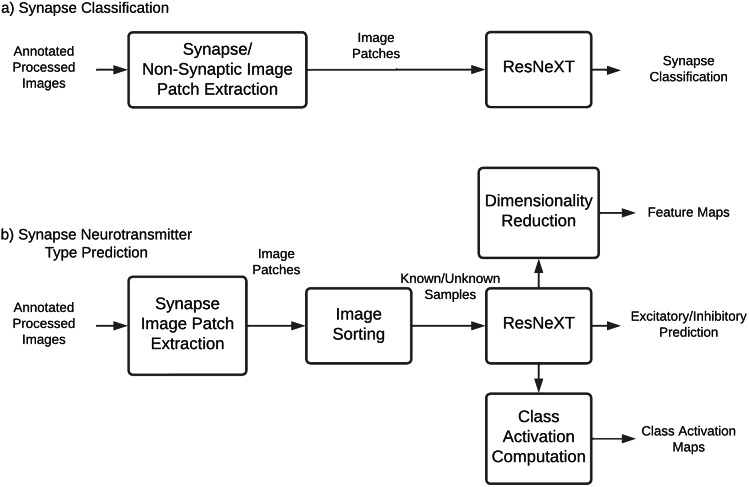
The major steps involved in Ciona synapse classification are shown in Figure 4. The synapse classification workflow includes image patch extraction and training of a ResNeXT network. The neurotransmitter prediction workflow is similar but sorts the images based on the assigned IDs(1) of the presynaptic cell before training the deep learning network. Post-prediction class activation maps of the convolutional neural network are computed for ba etter understanding of important imaging features for neurotransmitter-type prediction. Feature maps are reduced to two-dimensional space and plotted to visualize the feature-space distance between synapses of various neurotransmitter types.
Figure 4.
EM image processing flowcharts.
For synapse classification, the same training process is used as follows. A ResNeXt-50 network architecture(17) pretrained on the ImageNet(2) dataset was retrained on the extracted image patches. First, the last fully connected layer was replaced with a randomly initialized fully connected layer with an input of 2,048 and an output of 2. The output has two possible classes, with 0 being inhibitory and 1 being excitatory. The training was done in two sessions. First, all layers of the ResNeXt are “frozen,” with no gradient, except for the last fully connected layer. The model is trained for 100 epochs, and the best model is used for the second round of training. On the second round of training, the entire network is “unfrozen,” and every layer of the network is tuned with retraining for 200 epochs. The architecture of the deep network is shown in Table 1.
Table 1.
ResNeXt-50 architecture.
| Stage | Layers | Output | |
|---|---|---|---|
| Conv1 | 7 × 7, 64 | Stride 2 | 112 × 112 |
| Conv2 (×3) | 3 × 3 max pool | Stride 2 | 56 × 56 |
| 1 × 1, 128 | C = 32 | ||
| 3 × 3, 128 | |||
| 1 × 1, 256 | |||
| Conv3 (×4) | 1 × 1, 256 | C = 32 | 28 × 28 |
| 3 × 3, 256 | |||
| 1 × 1, 512 | |||
| Conv4 (×6) | 1 × 1, 512 | C = 32 | 14 × 14 |
| 3 × 3, 512 | |||
| 1 × 1, 1,024 | |||
| Conv5 (×3) | 1 × 1, 1,024 | C = 32 | 7 × 7 |
| 3 × 3, 1,024 | |||
| 1 × 1, 2,048 | |||
| Global average pool | |||
| 1,000-d fc, softmax | Prediction (0 or 1) |
4.1. Synapse classification
Image patches containing annotated synapses and image patches containing nonsynaptic structures were used for the training (80%) and testing (20%) sets. A total of 1,400 500 × 500 image patches containing synapses, and 1,392 500 × 500 image patches containing nonsynaptic structures, were used for training a synapse classification network. Nonsynaptic structures used were annotated variously as botrysomes, coated vesicles, basal bodies, and autophagosomes. Annotated structures that were avoided due to the possibility of synapses being in the same patch included terminals, vesicles, dense core vesicles, and gap junctions. Misclassified patches are analyzed visually for confounding factors.
4.2. Synapse neurotransmitter prediction
Image patches were grouped by presynaptic and postsynaptic cell ID(1) before splitting into training, validation, and testing sets. A similarity computation was applied to each patch to ensure that no duplicates or extremely overlapping patches were used. Due to the limited number of synapses and known neuron groups available, we combined the two inhibitory neurotransmitter types (glycine and gamma-aminobutyric acid [GABA]) and the two excitatory neurotransmitter types (glutamate and acetylcholine). A total of 470 excitatory synapses and 338 inhibitory synapses were used for training a synapse classification network. A total of 1,246 excitatory synapses and 396 inhibitory synapses were used for testing. Each synapse was composed of 3–10 image patches in the z-dimension.
Nine neuron groups with four known neurotransmitter types, as determined by in situ hybridization(3), were used in training and testing. Each presynaptic neuron had 1–41 associated synapses. Neurotransmitter class was predicted using the trained network on an additional 13 neuron groups with previously unknown neurotransmitter types. For each presynaptic neuron, a majority vote was made from the predictions of each synapse belonging to the neuron. Based on the strength of consensus, network confidence, and prior knowledge from in situ hybridization experiments(3), predictions were made on the neurotransmitter type of neurons that surpassed a confidence interval described as follows. For each neuron, we tallied the number of predictions for each neurotransmitter valence. This tally is referred to as a vote. The valence with the most votes is chosen as the raw prediction of that presynaptic neuron. If the votes for each valence are close (e.g., inhibitory vote is not more than
 times of the excitatory votes) or that the total number of votes is less than 3, we determine the prediction to be inconclusive.
4.3. Class activation maps
The patterns picked up by the deep-learning network might provide insights to the features visible in the EM image that may connect synapse form to function.
A total of 512 × 512 image patches with labels are passed through the neurotransmitter prediction neural network. The final layer of our network uses global average pooling to go from a size of 16 × 16 × 2,048 to 2,048 features, then compute probabilities for each of the N classes using a fully connected layer without bias. For each pixel in the 16 × 16 feature map, we then compute the amount that this feature contributes to the output class. We apply the fully connected weights to the features at each pixel, cutting out the average pooling step. The basic idea for deriving class activation maps is described in Reference (18). After extracting the activation maps from the model, we use connected component analysis to find seed points, then employ a watershed algorithm to segment the activation map into disjoint regions to further analyze spatial and intensity information about the activations. Next, we removed regions that were smaller than a set threshold, which was set empirically to 5,000 pixels. Following this step, for each remaining connected region, we then calculated the x- and y-coordinates of the centroid for the region and the average activation intensity inside the region of interest.
4.4. Feature maps
To see how the image features detected by the deep network relate to neurotransmitter type, we perform t-distributed Stochastic Neighbor Embedding(19) after principal component analysis (PCA) to visualize the features.
The t-SNE plot shows the feature projection of each individual synapse, not grouping the synapses by cell. The high-dimensional features from the output layer of the prediction network were reduced to 20 dimensions using PCA. The 20-dimensional feature is then further reduced to two dimensions using t-SNE, which better visualizes the clustering characteristics of the features. The features are grouped in various ways to gain more insight into how they are clustered.
5. Results
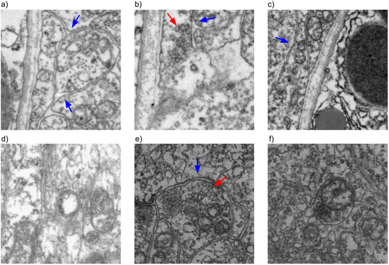
For synapse classification, a training accuracy of 0.99 and a testing accuracy of 0.98 were achieved. For training, 2,780 samples were used, with half of the samples containing synapses and half without synapses. For testing, 692 samples were used, also with a 50/50 split of synapse versus nonsynapse sample. There were no false negatives, but there were 13 false positives, which were detected by the model. Examples of some false positives are shown in Figure 12.
Performance of the network on neurotransmitter-type prediction is shown in Table 2 and Table 3. Precision is the number of true positives (TPs) divided by the sum of TPs and true negatives, and recall is TPs divided by the total number of positive samples. Precision determines how often selected items are relevant, and recall determines how often relevant items are selected.
Table 2.
Automated neurotransmitter prediction performance—per synapse (train and test) and per cell.
| Precision (per synapse) | Recall (per synapse) | Precision (per cell) | Recall (per cell) | |
|---|---|---|---|---|
| Inhibitory | 0.98 train/0.98 test | 0.93 train/0.91 test | 1.0 | 0.95 |
| Excitatory | 0.96 train/0.93 test | 0.99 train/0.99 test | 0.98 | 1.0 |
Table 3.
Automated synapse neurotransmitter-type performance breakdown by neurotransmitter type. As seen in the table, the performance for glycine was the worst, most likely due to the low number of cells and synapses available to train the model. Performance for GABA, acetylcholine, and glutamate were similar to each other. Each cell contains multiple 500 × 500 pixel patches of synapses spread throughout 3D space and may or may not be overlapping.
| Number of cells | Number of synapses | Accuracy (per cell) | Accuracy (per synapse) | |
|---|---|---|---|---|
| Gly | 3 | 22 | 0.67 | 0.71 train/0.6 test |
| GABA | 19 | 457 | 1.0 | 0.92 train/0.95 test |
| Ach | 19 | 292 | 1.0 | 0.97 train/1.0 test |
| Glut | 23 | 342 | 1.0 | 1.0 train/0.98 test |
| Overall | 64 | 1,113 | 0.98 | 0.95 train/0.97 test |
Abbreviation: GABA, gamma-aminobutyric acid.
Of the failed predictions (all false positives), 10 cases were image patches annotated as coated vesicles, 2 cases were annotated as botrysomes, and 1 case was annotated as an autophagosome. Some representative patches are included in Figure 12. From the failed cases, it can be seen that they tend to contain cell boundaries and vesicles, which are features associated with synapses. The lack of false negatives is reassuring, as the goal of the classification network is to detect likely synapses for screening by experts, so false positives are better tolerated than false negatives.
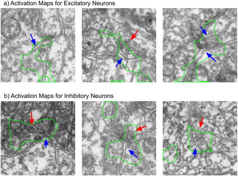
To get a better idea of the features that are important to the neurotransmitter predictor network, we visualized the activation maps of the network on different classes, as described in Section 4. The results of the visualization show that cell boundaries, vesicles, and postsynaptic density are the main focus of the majority of the attention for the trained network. Some examples of activation maps are shown in Figure 5.
Figure 5.
Processed class activation maps for excitatory and inhibitory synapse image patches. The network seems to pay more attention to the vesicles when predicting inhibitory neurons, and the cell boundary when predicting excitatory neurons. The blue arrows indicate cell boundaries, whereas the red arrows indicate vesicles. The green outline shows the main region of interest of the network.
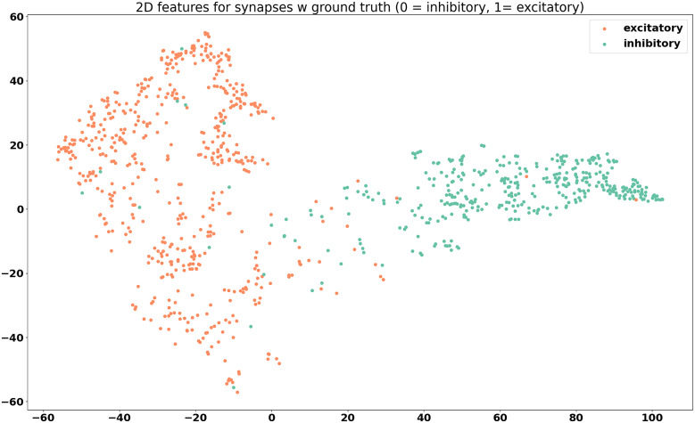
The feature maps derived from the model outputs are shown in Figures 6– 8.
Figure 7.
Feature visualization for synapses belonging to cells with known neurotransmitter type, grouped by valence. Two distinct groups can be seen.
Figure 6.
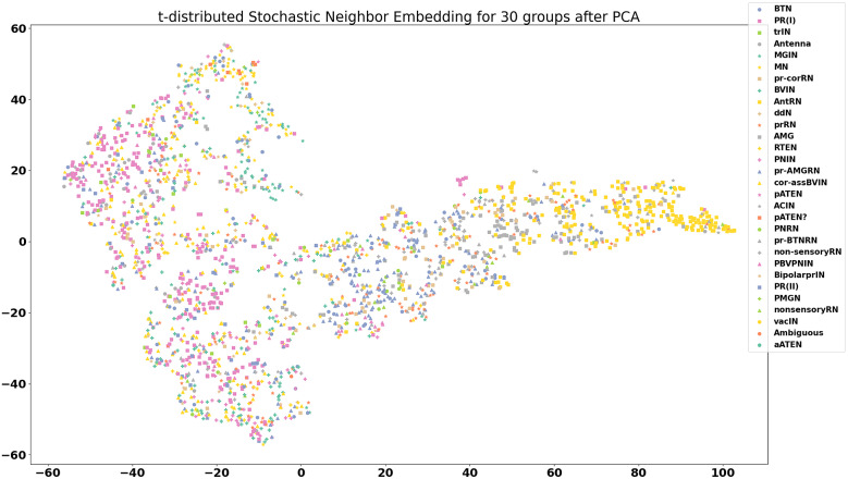
Visualization of features for 30 neuron groups after reduction to two dimensions using principal component analysis and t-distributed stochastic neighbor embedding. Each data point on the plot is the computed feature of a synapse, with synapses that span multiple frames averaged across all frames. There is quite a bit of intermingling of the features between cell groups, which is an encouraging sign that the model is picking up on differences not unique to each cell type.
Figure 8.
Feature visualization for synapses with known neurotransmitter type, grouped by neurotransmitter. Even though the prediction model was trained only to differentiate between excitatory and inhibitory synapses, it seems that the features tend toward separation by neurotransmitter type, with the exception of glycine, again likely due to the lack of training samples.
From the feature maps, it is evident that the synapses are placed in clusters that mostly correspond to their neurotransmitter class, inhibitory, or excitatory. From Figure 8, it appears that the differences between different excitatory neurotransmitters (acetylcholine and glutamate) are also captured by the model, even though this information was not explicitly included during the training. From Figure 6, it can be seen that the features of synapses tend to be spread out throughout the feature space, and co-mingle among cell groups. This is promising, because this indicates that the model is picking up on differences between synapses that are more indicative of neurotransmitter class, rather than group-specific differences.
Table 5 shows the performance of the model on synapses belonging to cells of known neurotransmitter type. Some of these synapses were used for training, and others were used for testing. We tallied the number of predictions by presynaptic neuron type and valence (inhibitory and excitatory) in the training set. The tally is repeated for the testing set. The tally for each valence is referred to as a vote. The valence with the most votes is chosen as the raw prediction of that presynaptic neuron. Those are the values in the Predicted Valence section. We compared the valence of the raw prediction with the neurotransmitter type determined by in situ hybridization to calculate precision and recall.
Table 4 shows the predictions of the model on RNs of unknown neurotransmitter type. We noticed that the prediction model tends toward predicting more excitatory synapses in the RN group, since the observed average number of excitatory RNs from in situ hybridization was 11, while the number of predicted excitatory RNs was 14(3). All but one of the pr-AMG RNs was predicted to be excitatory, with varying degrees of likelihood. This is different from our predictions in Reference (11), which indicated an inclination toward inhibitory pr-AMG RNs, but with low confidence. However, the predicted number of excitatory and inhibitory neurons in the RN group is closer to the observed number in Reference (3) than the predicted results from 3D point cloud matching, which suggests a promising direction for resolving the neurotransmitter types in that region. Further experiments and analysis are needed to determine with certainty the neurotransmitter type of each RN.
Table 4.
Predicted neurotransmitter valence for the relay neurons (RNs). RNs used for training with known neurotransmitter type are omitted from this table and included in the Appendix. The column with our model predictions is “Network prediction,” which is “inconclusive” if there are fewer than three synapses for a given cell, or if the number of excitatory and inhibitory predictions are similar, that is, one is not more than 1.5 times the other.
| Name | Cell group | Excitatory voxel | Inhibitory voxel | Excitatory score | Inhibitory score | Network prediction | Overlay estimation |
|---|---|---|---|---|---|---|---|
| 90 | Bipolar prIN | 6,234 | 532 | 1.10E-02 | 1.40E-03 | Excitatory | Excitatory |
| 92 | Bipolar prIN | 6,767 | 259 | 1.20E-02 | 6.79E-04 | Excitatory | Excitatory |
| 93 | Non-sensory RN | 308 | 905 | 5.44E-04 | 2.37E-03 | Inconclusive | Inconclusive |
| 103 | Non-sensory RN | 5 | 867 | 8.84E-06 | 2.27E-03 | Excitatory | Inconclusive |
| 106 | Non-sensory RN | 51 | 1,924 | 9.01E-05 | 5.05E-03 | Inconclusive | Inhibitory |
| 122 | Non-sensory RN | 25 | 2,113 | 4.42E-05 | 5.54E-03 | Excitatory | Inhibitory |
| 125 | Non-sensory RN | 83 | 12,696 | 1.47E-04 | 3.33E-02 | Inhibitory | Inhibitory |
| 4 | PNIN | 0 | 0 | 0 | 0 | Excitatory | Inconclusive |
| 6 | PNIN | 0 | 0 | 0 | 0 | Excitatory | Inconclusive |
| 20 | PNIN | 0 | 0 | 0 | 0 | Excitatory | Inconclusive |
| 29 | PNIN | 0 | 0 | 0 | 0 | Excitatory | Inconclusive |
| 30 | PNIN | 0 | 0 | 0 | 0 | Excitatory | Inconclusive |
| 85 | PNIN | 6,909 | 484 | 1.22E-02 | 1.27E-03 | Excitatory | Excitatory |
| 61 | PNIN | 1,673 | 0 | 2.96E-03 | 0 | Excitatory | Excitatory |
| 65 | PNIN | 8,273 | 146 | 1.46E-02 | 3.83E-04 | Excitatory | Excitatory |
| 88 | PNIN | 13,979 | 236 | 2.47E-02 | 6.19E-04 | Excitatory | Excitatory |
| 131 | PNRN | 1 | 6,828 | 1.77E-06 | 1.79E-02 | Excitatory | Inhibitory |
| 74 | pr-AMG RN | 1,665 | 0 | 2.94E-03 | 0 | Excitatory | Excitatory |
| 94 | pr-AMG RN | 8,900 | 9,602 | 1.57E-02 | 2.52E-02 | Excitatory | Inconclusive |
| 108 | pr-AMG RN | 5,903 | 1,558 | 1.04E-02 | 4.09E-03 | Excitatory | Inconclusive |
| 116 | pr-AMG RN | 7,398 | 423 | 1.31E-02 | 1.11E-03 | Inconclusive | Excitatory |
| 124 | pr-AMG RN | 6,215 | 6,184 | 1.10E-02 | 1.62E-02 | Excitatory | Inconclusive |
| 127 | pr-AMG RN | 871 | 6,454 | 1.54E-03 | 1.69E-02 | Excitatory | Inhibitory |
| 140 | pr-AMG RN | 1,485 | 7,463 | 2.62E-03 | 1.96E-02 | Excitatory | Inconclusive |
| 157 | pr-AMG RN | 941 | 3,979 | 1.66E-03 | 1.04E-02 | Inconclusive | Inconclusive |
| 123 | pr-BTN RN | 6,077 | 2,991 | 1.07E-02 | 7.84E-03 | Inconclusive | Inconclusive |
| 130 | pr-BTN RN | 312 | 84 | 5.51E-04 | 2.20E-04 | Inhibitory | Inconclusive |
| 105 | pr-cor RN | 2,953 | 760 | 5.22E-03 | 1.99E-03 | Inconclusive | Excitatory |
| 112 | pr-cor RN | 197 | 6,530 | 3.48E-04 | 1.71E-02 | Inconclusive | Inhibitory |
| 119 | pr-cor RN | 236 | 3,234 | 4.17E-04 | 8.48E-03 | Inconclusive | Inhibitory |
| 80 | prRN | 2,301 | 1,352 | 4.07E-03 | 3.55E-03 | Inconclusive | Inconclusive |
| 86 | prRN | 4,822 | 1,696 | 8.52E-03 | 4.45E-03 | Inconclusive | Inconclusive |
| 96 | prRN | 3,660 | 4,863 | 6.47E-03 | 1.28E-02 | Excitatory | Inconclusive |
| 100 | prRN | 174 | 11,273 | 3.08E-04 | 2.96E-02 | Inconclusive | Inhibitory |
| 121 | prRN | 751 | 7,371 | 1.33E-03 | 1.93E-02 | Inconclusive | Inhibitory |
| 126 | prRN | 1,096 | 4,588 | 1.94E-03 | 1.20E-02 | Inconclusive | Inhibitory |
The full prediction table is included in Table 5 in the Appendix. Summaries of the available data are shown in Figures 9 and 10.
Figure 9.
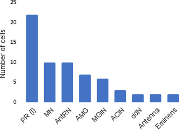
Number of unique cells per cell type of selected groups of interest.
Figure 10.
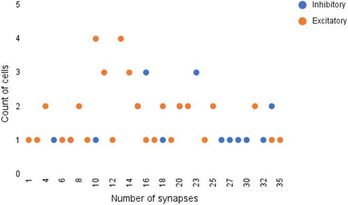
Frequency of cells with various number of synapses. It can be seen that the majority of cells have between 10 and 20 synapses.
5.1. Comparison with manual overlay
The crux of our analysis lies in our hypothesis that the same cells appear in similar locations across Ciona specimens. To provide an additional point of comparison, we manually overlay the fluorescent imaging results from in situ hybridization with the cell centroids provided by the annotated EM data, as seen in Figure 11. Using the Unity software(20), the centroid and volume of each neuron in the four selected cell groups as given in Reference (1) are rendered in 3D. Each neuron is approximated with a sphere of its corresponding volume. As seen on the leftmost image in Figure 9, image stacks of in situ from Reference (3) that contain expression of both vesicular GABA transporter (VGAT, inhibitory) and vesicular acetylcholine transporter (VAChT, excitatory) in the posterior Brain Vesicle are also rendered into the software with real-world dimensions. Since certain parts of the VGAT structure are well known and consistent, such as in the photoreceptors and at the posterior end of the RNs, this was used to manually align the in situ with the connectome. The matching criteria are as follows: the posterior border does not extend beyond the most posterior antRN, the dorsal cap marks the Eminen cells, and the two patches, a smaller posterior one and a larger anterior one, on the right mark the two photoreceptor groups, PR-I (only pr9 and pr10) and PR-II, respectively. After this alignment is done, the smaller VAChT-labeled regions are brought into view for analysis. Seven in situs from Reference (3) are aligned using the mentioned structures and similarity across the in situs as guides. Once they are aligned, a collision detector is used to compute the number of voxels in contact with each neuron. An illustration of the matching process is shown in Figure 11, and the comparative results are shown in Table 4.
Figure 11.
Illustration of manual overlay of in situ hybridization results for VGAT (left image) and EM-derived cell centroids (middle image) in 3D. Of the four cell groups shown, the areas with VGAT are encapsulated by the cell models, as seen in the rightmost image. See the text for more details.
6. Discussion
The proposed model has good performance on the classification of synapses in EM for Ciona. While there are some false positives from the model prediction (Table 1), this is desirable compared with false negatives, because an expert can then screen the predictions to determine true synapses. The ratio of synapses to nonsynaptic structures in a typical EM of Ciona is on the order of 1:1,000. Instead of scanning an entire image for possible synapses, the model can drastically reduce the annotation time needed for synapse annotation. The synapse prediction model has helped to identify possible neurotransmitter types for cells from certain neuronal groups, which were previously unknown. While we cannot be absolutely certain that the model has predicted correctly for synapses belonging to cells with previously unknown neurotransmitter types, the output of the model seems reasonable given the feature analysis we have done. Comparison with previous in situ hybridization results have also shown that the prediction of the model is likely correct. For the RNs, in Reference (3), we had previously found an average of 16 VGAT-positive neurons and 11 VAChT-positive neurons. The prediction of the network matches these numbers well, and much better than the point-cloud registration method used in Reference (3). We hope that the model predictions will work in conjunction with both prior and future analyses to help resolve the neurotransmitter type of individual neurons in regions that have been difficult to resolve using in situ hybridization and other experimental methods.
More work can be done on the analysis of cellular and subcellular features in neurons with undetermined neurotransmitter type. Overall connectivity and cell shape can be obtained from the annotated EM data and may be useful tools in better understanding the relationship between structural features and neurotransmitter-type expression. The connection between cell group and synapse structure can also be further explored, and may help with a more robust neurotransmitter prediction method. Additionally, detailed cell segmentation annotations could be created and added as another potential feature for analysis.
Acknowledgement
Thanks to Dr. Ian Meinertzhagen for his continued support of the project.
Appendix
Table 5.
Ground truth predictions.
| Cell ID | In situ | LLR test | LLR train | Excitatory test | Inhibitory test | Excitatory train | Inhibitory train | Prediction test | Prediction train |
|---|---|---|---|---|---|---|---|---|---|
| ACIN1L | Gly | 0.24 | −1.73 | 1 | 0 | 0 | 6 | Excitatory | Inhibitory |
| ACIN2L | Gly | −0.68 | 0.12 | 1 | 2 | 4 | 3 | Inhibitory | Excitatory |
| ACIN2R | Gly | −0.46 | −0.54 | 0 | 1 | 1 | 3 | Inhibitory | Inhibitory |
| AMG1 | GABA | −1.08 | −1.66 | 0 | 5 | 1 | 9 | Inhibitory | Inhibitory |
| AMG2 | GABA | −0.67 | −3.09 | 1 | 4 | 1 | 14 | Inhibitory | Inhibitory |
| AMG3 | GABA | −0.21 | −3.59 | 0 | 1 | 0 | 14 | Inhibitory | Inhibitory |
| AMG4 | GABA | −0.47 | −2.42 | 0 | 2 | 2 | 12 | Inhibitory | Inhibitory |
| AMG5 | Ach | 2.49 | 2.87 | 8 | 0 | 14 | 2 | Excitatory | Excitatory |
| AMG6 | GABA | −0.49 | −3.55 | 1 | 2 | 1 | 14 | Inhibitory | Inhibitory |
| AMG7 | GABA | −0.6 | −3.1 | 0 | 3 | 1 | 16 | Inhibitory | Inhibitory |
| Ant1 | Glut | 0.21 | 3.89 | 3 | 1 | 14 | 0 | Excitatory | Excitatory |
| Ant2 | Glut | 2.46 | 7.25 | 9 | 0 | 25 | 1 | Excitatory | Excitatory |
| 120 | GABA | −1.56 | −11.75 | 0 | 4 | 1 | 29 | Inhibitory | Inhibitory |
| 134 | GABA | −1.58 | −6.74 | 0 | 5 | 1 | 20 | Inhibitory | Inhibitory |
| 135 | GABA | −1.15 | −5.12 | 0 | 3 | 1 | 19 | Inhibitory | Inhibitory |
| 142 | GABA | −1.54 | −7.14 | 0 | 5 | 2 | 23 | Inhibitory | Inhibitory |
| 143 | GABA | −1.75 | −6.55 | 0 | 5 | 3 | 20 | Inhibitory | Inhibitory |
| 147 | GABA | −2.94 | −7.12 | 0 | 7 | 0 | 20 | Inhibitory | Inhibitory |
| 152 | GABA | −2.58 | −5.79 | 0 | 8 | 3 | 21 | Inhibitory | Inhibitory |
| 153 | GABA | −1.52 | −3.36 | 0 | 5 | 1 | 10 | Inhibitory | Inhibitory |
| 159 | GABA | −1.79 | −5.6 | 0 | 5 | 2 | 16 | Inhibitory | Inhibitory |
| 161 | GABA | −3.02 | −5.22 | 0 | 6 | 1 | 16 | Inhibitory | Inhibitory |
| ddNL | Ach | 1.39 | 4.69 | 4 | 0 | 16 | 0 | Excitatory | Excitatory |
| ddNR | Ach | 1.37 | 3.79 | 4 | 0 | 12 | 0 | Excitatory | Excitatory |
| Em1 | GABA | −1.11 | −7.92 | 1 | 6 | 3 | 31 | Inhibitory | Inhibitory |
| Em2 | GABA | −1.6 | −6.26 | 1 | 6 | 3 | 24 | Inhibitory | Inhibitory |
| MGIN1L | Ach | 0.87 | 6.27 | 5 | 0 | 25 | 1 | Excitatory | Excitatory |
| MGIN1R | Ach | 0.43 | 6 | 3 | 0 | 22 | 0 | Excitatory | Excitatory |
| MGIN2L | Ach | 0.82 | 4.85 | 3 | 0 | 14 | 0 | Excitatory | Excitatory |
| MGIN2R | Ach | 2.01 | 3.88 | 6 | 0 | 14 | 1 | Excitatory | Excitatory |
| MGIN3L | Ach | 0.33 | 2.91 | 1 | 0 | 7 | 0 | Excitatory | Excitatory |
| MGIN3R | Ach | 0.68 | 2 | 2 | 0 | 7 | 1 | Excitatory | Excitatory |
| MN1L | Ach | 1.13 | 5.77 | 3 | 0 | 18 | 0 | Excitatory | Excitatory |
| MN1R | Ach | 2.9 | 3.85 | 8 | 0 | 16 | 1 | Excitatory | Excitatory |
| MN2L | Ach | 1.84 | 3.46 | 4 | 0 | 9 | 0 | Excitatory | Excitatory |
| MN2R | Ach | 1.56 | 4.81 | 4 | 0 | 11 | 0 | Excitatory | Excitatory |
| MN3L | Ach | 0.43 | 1.91 | 1 | 0 | 5 | 0 | Excitatory | Excitatory |
| MN3R | Ach | 0.85 | 2.77 | 3 | 0 | 7 | 0 | Excitatory | Excitatory |
| MN4L | Ach | 1.91 | 1.02 | 6 | 0 | 4 | 0 | Excitatory | Excitatory |
| MN4R | Ach | 0.76 | 2.92 | 2 | 0 | 7 | 0 | Excitatory | Excitatory |
| MN5L | Ach | 0.4 | 1.34 | 1 | 0 | 3 | 0 | Excitatory | Excitatory |
| MN5R | Ach | 0.37 | 2.54 | 1 | 0 | 6 | 0 | Excitatory | Excitatory |
| pr1 | Glut | 1.5 | 2.05 | 4 | 0 | 9 | 0 | Excitatory | Excitatory |
| pr11 | Glut | 0.67 | 2.41 | 3 | 0 | 10 | 0 | Excitatory | Excitatory |
| pr12 | Glut | 0.85 | 4.72 | 3 | 0 | 16 | 0 | Excitatory | Excitatory |
| pr13 | Glut | 1.1 | 2.96 | 3 | 0 | 11 | 0 | Excitatory | Excitatory |
| pr14 | Glut | 0.16 | – | 1 | 0 | 0 | 0 | Excitatory | Excitatory |
| pr15 | Glut | 1.98 | 7.33 | 7 | 0 | 27 | 0 | Excitatory | Excitatory |
| pr16 | Glut | 0.89 | 1.83 | 3 | 0 | 7 | 0 | Excitatory | Excitatory |
| pr17 | Glut | 0.44 | 3.35 | 2 | 0 | 13 | 0 | Excitatory | Excitatory |
| pr18 | Glut | 0.14 | 0.58 | 1 | 0 | 2 | 0 | Excitatory | Excitatory |
| pr19 | Glut | 1.38 | 1.48 | 5 | 0 | 7 | 0 | Excitatory | Excitatory |
| pr2 | Glut | 0.39 | 1.3 | 2 | 0 | 6 | 0 | Excitatory | Excitatory |
| pr20 | Glut | 2.92 | 5.94 | 9 | 0 | 22 | 0 | Excitatory | Excitatory |
| pr21 | Glut | 0.43 | 2.18 | 2 | 0 | 9 | 0 | Excitatory | Excitatory |
| pr22 | Glut | 0.58 | 2.4 | 3 | 0 | 10 | 0 | Excitatory | Excitatory |
| pr23 | Glut | 1.06 | 4.16 | 4 | 0 | 14 | 0 | Excitatory | Excitatory |
| pr3 | Glut | 0.54 | 3.06 | 2 | 0 | 12 | 0 | Excitatory | Excitatory |
| pr4 | Glut | 0.66 | – | 3 | 1 | 0 | 0 | Excitatory | Excitatory |
| pr5 | Glut | 0.85 | 2.41 | 3 | 0 | 8 | 0 | Excitatory | Excitatory |
| pr6 | Glut | 0.75 | 2.14 | 2 | 0 | 9 | 0 | Excitatory | Excitatory |
| pr7 | Glut | 1.18 | 4.82 | 4 | 0 | 16 | 0 | Excitatory | Excitatory |
| pr8 | Glut | 0.66 | 2.7 | 3 | 0 | 11 | 0 | Excitatory | Excitatory |
| pr9 | GABA | −0.36 | −1.3 | 0 | 1 | 4 | 11 | Inhibitory | Inhibitory |
Figure 12.
Examples of false positives for the synapse classification network. (a)–(c) contain coated vesicles, (d) and (e) contain botrysomes, and (f) contains an autophagosome. It can be seen that either cell boundaries (blue arrows) or groups of vesicles (red arrows) are visible in many of the cases.
Consent for Publication
All authors have provided consent for publication.
Competing Interests
The authors declare that they have no competing interests.
Authorship Contributions
A.Z. conceptualized the idea, developed the models and algorithms, and wrote the paper. S.S. extracted the data from RECONSTRUCT. C.B. developed the method to compare expected results using the manual overlay. Y.M. developed the uncertainty measurements and created the tables. M.G. and R.R. developed the code for Class Activation Maps. K.R. conducted the experiments and created the annotations, which provided the data for this paper. W.S. and B.S.M. supervised the project and provided directional advice.
Funding Statement
The research in this paper was funded by NS103774 from the National Institute of Neurological Disorders and Stroke (NINDS) and the US National Science Foundation Award #1664172.
Data Availability Statement
Data and materials are available upon request.
References
- 1.Ryan K, Lu Z & Meinertzhagen IA (2016) The CNS connectome of a tadpole larva of Ciona intestinalis (L.) highlights sidedness in the brain of a chordate sibling. eLife 5, 16962. doi: 10.7554/eLife.16962. [DOI] [PMC free article] [PubMed] [Google Scholar]
- 2.Deng, J., Dong, W., Socher, R., Li, L., Li Kai, Fei-Fei Li: ImageNet: a large-scale hierarchical image database. In 2009 IEEE Conference on Computer Vision and Pattern Recognition, pp. 248–255 (2009). doi: 10.1109/CVPR.2009.5206848. ISSN: 1063–6919 [DOI] [Google Scholar]
- 3.Kourakis MJ, Borba C, Zhang A, et al. (2019) Parallel visual circuitry in a basal chordate. eLife 8, 44753. doi: 10.7554/eLife.44753. [DOI] [PMC free article] [PubMed] [Google Scholar]
- 4.Selvaraju RR, Cogswell M, Das A, Vedantam R, Parikh D & Batra D (2017) Grad-CAM: visual explanations from deep networks via gradient-based localization. In: 2017 IEEE International Conference on Computer Vision (ICCV), pp. 618–626. doi: 10.1109/ICCV.2017.74. [DOI] [Google Scholar]
- 5.Huang GB, Scheffer LK & Plaza SM (2018) Fully-automatic synapse prediction and validation on a large data set. Front Neural Circuits 12. doi: 10.3389/fncir.2018.00087. [DOI] [PMC free article] [PubMed] [Google Scholar]
- 6.Kreshuk A, Koethe U, Pax E, Bock DD & Hamprecht FA (2014) Automated detection of synapses in serial section transmission electron microscopy image stacks. PLoS One 9(2), 87351. doi: 10.1371/journal.pone.0087351. [DOI] [PMC free article] [PubMed] [Google Scholar]
- 7.Staffler B, Berning M, Boergens KM, Gour A, van der Smagt P & Helmstaedter M (2017) SynEM, automated synapse detection for connectomics. eLife 6, 26414. doi: 10.7554/eLife.26414. [DOI] [PMC free article] [PubMed] [Google Scholar]
- 8.Buhmann J, Sheridan A, Malin-Mayor C, et al. (2021) Automatic detection of synaptic partners in a whole-brain Drosophila electron microscopy data set. Nat Methods 18(7), 771–774. doi: 10.1038/s41592-021-01183-7. [DOI] [PMC free article] [PubMed] [Google Scholar]
- 9.Liu Y & Ji S (2021) CleftNet: augmented deep learning for synaptic cleft detection from brain electron microscopy. IEEE Trans Med Imaging 40(12), 3507–3518. doi: 10.1109/TMI.2021.3089547. [DOI] [PMC free article] [PubMed] [Google Scholar]
- 10.Ronneberger O, Fischer P & Brox T (2015) U-net: convolutional networks for biomedical image segmentation. In Medical Image Computing and Computer-Assisted Intervention—MICCAI 2015, Lecture Notes in Computer Science, vol. 9351, pp. 234–241.Cham: Springer. doi: 10.1007/978-3-319-24574-4_28. [DOI] [Google Scholar]
- 11.Jagadeesh V, Anderson J, Jones B, Marc R, Fisher S & Manjunath BS (2014) Synapse classification and localization in electron micrographs. Pattern Recognit Lett 43, 17–24. doi: 10.1016/j.patrec.2013.06.001. [DOI] [Google Scholar]
- 12.Atwood HL, Lang F & Morin WA (1972) Synaptic vesicles: selective depletion in crayfish excitatory and inhibitory axons. Science 176(4041), 1353–1355. doi: 10.1126/science.176.4041.1353. [DOI] [PubMed] [Google Scholar]
- 13.Tao C-L, Liu Y-T, Sun R, et al. (2018) Differentiation and characterization of excitatory and inhibitory synapses by cryo-electron tomography and correlative microscopy. J Neurosci 38(6), 1493–1510. doi: 10.1523/JNEUROSCI.1548-17.2017. [DOI] [PMC free article] [PubMed] [Google Scholar]
- 14.Uchizono K (1965) Characteristics of excitatory and inhibitory synapses in the central nervous system of the cat. Nature 207(4997), 642–643. doi: 10.1038/207642a0. [DOI] [PubMed] [Google Scholar]
- 15.Eckstein N, Bates AS, Du M, Hartenstein V, Jefferis GSXE & Funke J (2020) Neurotransmitter classification from electron microscopy images at synaptic sites in Drosophila. Neuroscience, to appear. doi: 10.1101/2020.06.12.148775. [DOI] [PMC free article] [PubMed]
- 16.Fiala JC (2005) Reconstruct: a free editor for serial section microscopy. J Microsc 218(1), 52–61. doi: 10.1111/j.1365-2818.2005.01466.x. [DOI] [PubMed] [Google Scholar]
- 17.Xie S, Girshick R, Dollar P, Tu Z & He K (2017) Aggregated residual transformations for deep neural networks. In 2017 IEEE Conference on Computer Vision and Pattern Recognition (CVPR), pp. 5987–5995. Honolulu, HI: IEEE. doi: 10.1109/CVPR.2017.634. [DOI] [Google Scholar]
- 18.Zhou, B., Khosla, A., Lapedriza, A., Oliva, A., Torralba, A. (2016) Learning Deep Features for Discriminative Localization. In 2016 IEEE Conference on Computer Vision and Pattern Recognition (CVPR), pp. 2921–2929. Las Vegas, NV: IEEE. doi: 10.1109/CVPR.2016.319. [DOI] [Google Scholar]
- 19.van der Maaten L & Hinton G (2008) Visualizing data using t-SNE. J Mach Learn Res 9(86), 2579–2605. [Google Scholar]
- 20.Haas JK (2014) A history of the unity game engine.
Associated Data
This section collects any data citations, data availability statements, or supplementary materials included in this article.
Data Availability Statement
Data and materials are available upon request.


