

Summary
Large-scale complex underwater concrete structures have structural damage and the traditional damage detection method mostly uses manual identification, which is inaccurate and inefficient. Therefore, robotic detection systems have been proposed to replace manual identification for underwater concrete structures in ocean engineering. However, the highly corrosive and disruptive environment of the ocean poses great difficulties for the application. Here, we develop a manta ray-inspired underwater robot with well controllability to establish the damage datasets of underwater concrete structures, proposing the YOLOX-DG algorithm to improve the damage detection accuracy, and integrating the model into the robotic detection systems for underwater concrete damages. Eventually, the system is used for ocean testing in real applications (i.e., underwater marine harbors around the East China Sea), and satisfactory detection performance is obtained. The reported manta ray-inspired robotic detection system can be used to accurately monitor and analyze the underwater regions.
Subject areas: Artificial intelligence, Engineering, Robotics
Graphical abstract
Highlights
-
•
Manta ray-inspired chemical reaction-propeller dual-drive underwater
-
•
Real-site testing for underwater structures monitoring in the East China Sea
-
•
Fully open-source concrete damage datasets and YOLOX-DG model
Artificial intelligence; Engineering; Robotics
Introduction
Assessing and maintaining safety and stability has become increasingly crucial for large-scale underwater concrete structures.1,2,3,4,5 Given the limitation of manual inspection methods in highly relying on visual inspection, subjective judgment, and personal experience of inspectors, various robotic systems have been developed for automatic damage detection in recent years.6 Underwater robotic detection systems mainly consist of two functional components, including underwater robots and detection technologies. Compared to traditional methods, robotic damage detection systems offer higher efficiency and accuracy with less fewer risk factors (see Section S1). More importantly, small robots can effectively approach the complex regions that are unreachable for manual inspection, especially for large-scale complex underwater concrete structures.7
Detection technologies in underwater robotic systems mainly include machine vision8,9,10,11 and laser scanning.12,13,14,15 The former assesses structural damages by analyzing monitoring images, and the latter uses lasers to measure the shape and size of structural surfaces. Machine vision, such as pattern recognition (PR), excels at detecting changes in color, shape, and texture. It has the capability to capture images from various angles and is flexible in detecting structures with complex shapes or obstacles. On the contrary, laser scanning needs to be tailored to detect complex structures as the laser may have difficulty reaching the target surface. With its advantages in accuracy and convenience, different machine learning (ML) algorithms have been developed for PR of the concrete detection images.16,17 Currently, however, the existing ML algorithms still face the challenges of high computing cost and inadequacy in implementing edge computing.18,19,20,21 The variety of concrete damages in the existing datasets is low, while the quality of the images used for model training needs to be improved.22 In addition, the post-processing of the existing monitoring systems for underwater concrete structures is inadequate, which critically affects the repairing resolutions after identifying those damages.7
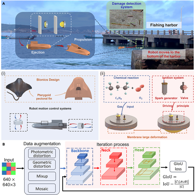
Here, we report the robotic detection systems inspired by manta ray for large-scale complex underwater concrete structures, which include the biomimetic robotic systems (Figure 1A) and concrete detection model (Figure 1B). The manta ray-inspired robots are developed to flexibly adjust postures23,24,25,26 in the underwater environments such as the bottom of marine harbors to monitor structural damages. Since sediment and water plants around harbors may entangle the underwater devices, the manta ray-inspired robots are designed with the transient driving method (TDM)27,28,29,30,31,32,33 component for reaching or getting rid of the monitoring regions by a sudden activation with high acceleration (i.e., within 0.01 s) (see Video S1). To minimize the influence of ocean waves on stability, the robots are designed with the self-adjusting balance function (see Videos S2 and S5). To develop the concrete detection model, we establish the concrete target detection datasets, dividing them into the four damage types of cracks, spalling, exposed reinforcement, and corrosion, collecting detection images accordingly, and marking the damage regions. The datasets have good annotation quality with good algorithm testing performance. Next, we expand the YOLOX34 algorithm to YOLOX-DG by enhancing the data augmentation and modifying loss function for underwater concrete structures with well damage detection performance, e.g., 4.5% for mAP0.5:0.95. is improved on the original basis. Eventually, the robotic detection systems have been applied for large-scale complex underwater concrete structures in real applications. Ocean testing has been conducted on the underwater marine harbors around Gouqi Island in the East China Sea with satisfactory detection performance. The reported manta ray-inspired robotic detection systems can be used to accurately monitor and analyze the underwater regions that are unreachable for typical underwater robots in complex underwater scenarios.
Figure 1.

Design principle of the robot and mechanism of the prediction system
(A) Illustration of the robotics and intelligent recognition system, the manta ray-inspired fast response robot swims into the bottom of the harbor to capture concrete structural damages. (i), The robot mimics manta ray in appearance for well controllability and is equipped with propeller system. (ii), The ejection system of the robot enables the robot to rapidly avoid obstacles and start-up.
(B) The illustration of the YOLOX-DG algorithm used in the detection system, including four steps Input, Data augmentation, Iteration process, and GIoU loss.
Results
Robotic systems
The robotic detection system proposed in this paper consists of both hardware and software components. First, we describe the fabrication process of the robot and its components. The fabrication of the manta ray-inspired robot can be divided into three steps, including the ejection, propulsion, and biomimetic body shell, as shown in Figure 2. Figure 2A demonstrates the fabrication process of the ejection actuator, chamber, and 3D-printed body shell. The soft membrane in the ejection actuator was made of silicon rubber. We poured the silicone gel A and B into the beaker in equal amounts and fully mixed. The mixed silicone gel was poured into a mold and cured at the room temperature for 8 h. The steel chamber was manufactured by the selective laser melting (SLM) technology, and the 3D printed manta ray-inspired body shell was made by the resin materials with the density close to water. Figure 2B presents the working schematic of the robotic detection systems. Smart phone was used to manipulate the robot’s movements through a Wi-Fi station. For example, when the robots needed to move fast for obstacle avoidance, the microcontroller unit (MCU) sent the control signal to the explosion module to actuate the ejection system (see Figures S1 and S2, and Tables S1–S3). The manta ray-inspired robots can adjust their attitude and position using the balance sensors and propellers. The camera on the head of the robots can capture the structural damage of the harbor and send video signals to the MCU for damage analysis. It is worth mentioning that we designed two powerful fill lights to address the issue of dim underwater light and murky water (see Video S6). Figure 2C shows the overall prototype and details of the 3D-printed manta ray-inspired robots. The length, width, and height are 54, 42, and 27 cm, and the cable is used to connect the robot and the Wi-Fi station.
Figure 2.

Fabrication of the manta ray-inspired fast-response robot
(A) Manufacturing process of the robot, including soft membrane, chamber and manta ray-inspired robot shell.
(B) The working schematic of the robot detection systems.
(C) Overall prototype and the details of the 3D printed robot shell size.
Setup of datasets
Deep learning (DL)-based computer vision techniques have the potential to extract and analyze an enormous volume of visual data generated from underwater robotic systems. However, datasets play a key role in training the DL models for accurately detecting and analyzing a diverse array of damage types. Therefore, it is imperative to stimulate the creation of more comprehensive and diverse annotated datasets that reflect the wide array of damage types and conditions on underwater concrete structures. In this study, we widely collect the relevant monitoring images to build high-quality datasets, including the three sources of concrete damage images taken from the underwater concrete structures located in Gouqi Island in the East China Sea, the concrete damage images collected online, and certain unmarked concrete images selected in CODEBRIM.35 The concrete images are divided into four damage types, i.e., crack, spalling, exposed reinforcement, and corrosion.
Figure 3A shows the sample images and labels of the four damage types in the dataset. Annotation of the images has been manually achieved using the LabelImage tool for target detection.36 The quality of the datasets determines the upper limit of the algorithm model, so to facilitate the subsequent optimization of the dataset and annotation methods, we make a statistical analysis of 3917 sample images and 6773 annotations of the datasets. Figure 3B shows the distribution of the labeled areas, where most of the labeled areas are located in the center of the images, and the rest of the labeled areas are evenly distributed in the corners and boundaries. Figure 3C shows that most sample points are densely distributed near the origin of the coordinate axis in terms of the size of the labeled areas, which indicates that the labeled areas of these datasets are relatively small. It can be seen that the datasets have certain advantages in small target monitoring. However, there are also a few marked areas where the width or height has reached 1 after normalization, indicating that their marks are across the entire image. Combined with the marking situation, they are considered as the crack targets. For target detection models, the images may have a negative impact on training and it is difficult to identify them during recognition, which affects the accuracy rate. Considering that there may be such cracks across the whole picture in actual working environments, we still choose to retain the labeled samples of these cracks. Concrete damages are usually found in a variety of shapes and sizes, and therefore, defects of different shapes and sizes need to be detected in concrete damage monitoring, rather than classifying or segmenting the entire images. Besides, the entire images need to be classified at the pixel level in the semantic segmentation algorithms, which brings in huge computational costs. Therefore, target detection algorithms are more efficient and suitable for mobile deployment, which is in line with the reported robotic detection systems for underwater concrete structures.
Figure 3.

The Dataset of the prediction model
(A) Sample damage pictures with labels, including crack, spalling, exposed reinforcement, and corrosion.
(B) Distribution of the labeled areas.
(C) Size of the labeled areas.
Model training and training results
Data augmentation is a commonly used method to boost the performance of a detector and reduce the risk of overfitting. Figures 4A–4D show the four types of data augmentation techniques applied in the training pipeline, namely photometric distortion, geometric distortion, mixup,37 and mosaic. Photometric distortion is adopted to reduce the model’s sensitivity to changes in illumination conditions in different scenes. Due to the changing positional relationship between the camera system and the damaged surface in practical applications, the perspective and scale of captured images can vary greatly. Geometric distortion is used to simulate this effect. Mixup and mosaic augmentation algorithms, which have been proved effective in YOLOv438 and YOLOv5,39 are leveraged to improve the model’s capability of detecting objects in complex backgrounds. Experiments have shown that these data augmentation strategies can significantly improve the model’s performance.
Figure 4.

Data augmentation techniques and training results
(A) Photometric distortion.
(B) Geometric distortion.
(C) Mixup.
(D) Mosaic.
(E) Ensembled results.
(F) Change in Map0.5 in three experiments including YOLOX, YOLOX-D, and YOLOX-DG.
(G) Change in mAP0.5:0.95 in three experiments.
To improve the convergence speed of the training loss and achieve more accurate prediction, we consider the generalized intersection over union (IoU) (GIoU) loss40 to replace the original IoU loss in the model. The calculation of GIoU loss with two arbitrary shapes A, B is given as
| (Equation 1) |
and the smallest enclosing convex object C given A and B is
| (Equation 2) |
IoU and GIoU can be calculated as
| (Equation 3) |
and
| (Equation 4) |
and therefore, IoU loss and GIoU loss are
| (Equation 5) |
In YOLOX, bounding box regression is used to predict the target objects’ location using rectangular bounding boxes. Bounding box regression uses the overlap area between the predicted bounding box and the ground truth bounding box referred to as IoU loss. IoU loss, however, will not provide any moving gradient for non-overlapping cases. Instead, GIoU loss maximizes the overlap area of the ground truth and predicted bounding box, which increases the predicted box’s size to overlap with the target box by moving slowly toward the target box for non-overlapping cases. With the introduced GIoU loss function, the test performance of the model witnessed a considerable enhancement.
Three sets of comparison experiments are conducted, including the plain YOLOX model, the YOLOX model using the data augmentation strategy (YOLOX-D), and the YOLOX model using the data augmentation strategy as well as the GIoU loss function (YOLOX-DG) (see Figure S4 and Section S4 and S5). Figures 4F and 4G show the changes of mAP in the three experiments. After 80 epochs of training, the mAP curves tend to smooth out and perform overfitting, and therefore, we only consider the results of 80 rounds in training, which can represent the upper limit of the model. The results show that the YOLOX-D model, though slower in convergence speed, has a better convergence result compared with the plain YOLOX model. The final mAP of the YOLOX-D model is 57.0 for mAP0.5:0.95 and 76.0 for mAP0.5, which is significantly better than that of the plain YOLOX model (i.e., 56.0 for mAP0.5:0.95 and 73.7 for mAP0.5). In addition, the YOLOX-DG model outperforms the YOLOX-D model, which obtains 58.5 for mAP0.5:0.95 and 78.0 for mAP0.5. The results show that we have improved the performance of the detector on the concrete damage datasets by 2.6% for mAP0.5 and 4.5% for mAP0.5:0.95.
Prediction results and postprocessing
Figure 5A displays the confusion matrix of the YOLOX-DG model, where no confusion among the four damage types is witnessed. The YOLOX-DG model performs the best on crack in the four kinds of damage identifications. On the contrary, spalling, exposed reinforcement and corrosion are all confused with the unlabeled backgrounds, including situations that damage areas being identified as background and the background being identified as damage areas. Figure 5B shows the P-R curve of the YOLOX-DG model, indicating that the model reaches a high level of precision. When IoU grows from 0.5 to 0.9 at a rate of 0.05 per step, it is found that the intersection of the P-R curve with the recall axis shifts to left at a gentle rate, and then steeply decline when IoU grows from 0.85 to 0.9. When the confidence threshold is very low, a large number of prediction boxes are generated by the model, leading the recall metrics to their maximum. When the IoU requirement grows to 0.9, large amounts of prediction boxes are no longer able to meet the IoU requirement. Two factors may cause this phenomenon, poor quality of annotation (i.e., inaccurate ground truth boxes boundaries), and limitation of the target detection model. After checking and re-testing the dataset annotations, it is found that the first possibility and the upper limit of YOLOX model accuracy is between IoU = 0.85–0.9.
Figure 5.

Prediction results of the YOLOX-DG model and postprocessing
(A) Normalized Confusion Matrix.
(B) Precision-Recall (P-R) Curve.
(C) The upper row shows the original pictures randomly selected in the datasets and the lower row shows the identification results with annotation using the YOLOX-DG model.
(D) Flowchart of the software, including the target detection and damage evaluation.
(E) Calculation of Rij in the multi-attribute decision algorithm for auxiliary assessment of damage degree.
(F) Curve of the sigmoid function.
(G) Curves of ti-Rif.
We performed a 5-fold cross validation and the results (see Figure S6) show that the randomness of dividing the dataset does not have a significant impact on the results and the model has a good generalization performance. In addition, we compared YOLOX-DG with YOLO v5, Faster-RCNN and other well-known target monitoring algorithms, and YOLOX-DG has the best performance (see Figure S5). Prediction results of the model are shown in Figure 5C, where the upper row shows the original images randomly selected in the datasets and the lower row displays the identification results with annotation using the YOLOX-DG model.
Apart from providing the damage prediction boxes, here we provide an additional comprehensive damage assessment algorithm to assist in judging the extent of concrete damage. Figure 5D displays the software system for underwater concrete detection (see Table S4), including the target detection algorithm (i.e., YOLOX-DG) and damage evaluation algorithm (i.e., multi-attribute decision). When the damage prediction boxes are obtained from the YOLOX-DG model, concrete damages in the images may still not be obvious, especially when the damages are serious. In addition, the prediction boxes in some regions may overlap each other, which results in the difficulty in distinguishing the damages. As a consequence, we developed the multi-attribute decision model to automatically calculate the image damage scores to provide assistance for further evaluation. Figure 5E shows that length and area can be used to calculate the proportion of the frame occupied by different types of damaged prediction boxes, i.e., . Different damage types have different impacts on structural safety, and different areas of damage in the robot’s line of sight area have different impacts on structural safety, we introduce a factor to measure that impact. So the damage score of a particular moment can be calculated as
| (Equation 6) |
In Equation 6, i from 1 to 4 denotes the four damage types of crack, spalling, exposed reinforcement, and corrosion, and ij denotes the jth damage prediction box for the ith damage in the images. Since the four kinds of damages often appear in different periods during the service of the underwater concrete structures, it is necessary to limit within a range, so that the initial value is distinguished, and the final value converges to the upper threshold.
Figure 5F presents the sigmoid function. The sigmoid function compresses any input value between 0 and 1 and is commonly used for data normalization. The output can be mapped to a range of probability values by
| (Equation 7) |
Equation 7 is used to normalize through the coordinate transformation, as shown in Figure 5G. Since the sequence of the four kinds of damage indirectly reflects the service time and damage degree of the underwater concrete structures, we assign different initial values to that eventually converge to 1 by increasing . The expression for is given as
| (Equation 8) |
The values of is shown in Table 1 based on the expert rating. According to the time sequence of concrete damage development, we determined the severity of four kinds of damage. Corrosion has the highest weight, because it is a relatively serious and dangerous concrete damage, and crack, as a common mild concrete damage, has the lowest weight. The damage score is intended to be a part of the robotic systems to provide the auxiliary judgment basis.
Table 1.
Weight coefficients of the four types of damages on underwater concrete structures
| Damage type | Crack | Spalling | Exp. reinf. | Corrosion |
|---|---|---|---|---|
| 0.1 | 0.3 | 0.5 | 0.7 |
Ocean testing in the East China Sea
Ocean testing was carried out on the reported manta ray-inspired robotic detection systems to monitor the damages of the underwater concrete structures (i.e., marine harbors) next to the Gouqi Island in the East China Sea. Figure 6A presents the location of the marine harbors in the ocean testing close to the Gouqi Island, which is located approximately 30 miles away from the Shanghai Shenjiawan Harbor. The concrete harbor next to the Gouqi Island has visible structural damages due to the ocean waves and tides, as shown in Figure 6A. To provide effective wave protection, the Gouqi Island Harbor is designed in the pile array structures; however, there are still severe wave erosions on the underwater regions of the harbor. The conventional structural monitoring equipment is unable to approach the harbor pile arrays. Therefore, it is essential for the developed manta ray-inspired underwater robots to reach these regions and monitor the structural damages on the pile-arrays (see Video S3).
Figure 6.

Ocean testing of the reported manta ray-inspired robotic detection systems
(A) Location of the ocean testing on the Gouqi Island Harbor in the East China Sea.
(B) Ejection and motion performance of the robots.
(C) Monitoring results on the underwater concrete structures and the damages analyzed by the detection systems. The detection system is able to recognize different types of structural damages, and mussel and kelp on the underwater concrete structures.
Figure 6B presents the entire robotic systems, including the ejection and robotic monitoring components. The robots are ejected from the fixture panel within 0.1 s to rapidly start for underwater motions. Next, the robots are controlled by the propellers to swim into the bottom of the wave-eroded pile arrays of the harbor. The robots swim straightly into the wave-eroded regions to monitor the structural health along the edge of the harbor, allowing for more comprehensive monitoring of structural damage. Figure 6C shows the results of the structural damages of the harbor monitored by the reported manta ray-inspired robots. We transmitted the monitoring images of damages to the damage detection system to recognize the four kinds of concrete damages and obtain damage scores accordingly. When the damage score exceeds the warning threshold, the robots return the coordinates for further repairing and treatment. Based on the damage images, it can be seen that the underwater concrete damages of the harbor are mainly caused by the wave and biological erosion (also see in Video S4). Note that mussels and water plants are also clearly observed in the monitoring images.
Discussion
This work proposes a novel manta ray-inspired robotic detection system for large-scale underwater concrete structures which is unreachable for normal monitoring robot. In order to improve the flexibility and stability of the robot, we design a manta ray-like robot and the robot is capable of adjusting posture autonomously due to balance sensors in the robot. Taking advantage of the TDM, we constructed an ejection system which enables manta ray-inspired robot to rapidly get rid of obstacles and startup. In the software part of the manta ray-inspired robotic detection system, we firstly establish a concrete damage target detection dataset, dividing into the four damage types of cracks, spalling, exposed reinforcement, and corrosion, collecting pictures and marking the damage areas. The dataset has good annotation quality with well algorithm testing performance. Next, we improved the performance of YOLOX algorithm in concrete damage target detection task in terms of the data augmentation and changing loss function. We used photometric distortion, geometric distortion, mixup and mosaic in data augmentation and changed IoU loss to GIoU loss, forming YOLOX-DG model. The new model improved 2.6% for mAP0.5 and 4.5% for mAP0.5:0.95 on the original basis. Eventually, we have proposed a manta ray-inspired robotic detection system which are used for ocean testing in real applications (i.e., underwater marine harbors around the Gouqi Island in the East China Sea) to monitor concrete damages. The target detection model (i.e., YOLOX-DG) and damage evaluation model (i.e., multi-attribute decision) provides assistance for human evaluation. The reported manta ray-inspired robotic detection systems can be used to efficiently monitor and analyze underwater regions which are unreachable for normal monitoring robot.
Limitations of the study
Further optimization is still required for the proposed robotic system. The limitations of this study can be summarized as follows.
-
(1)
Although the addition of the self-balancing module improves the stability of the robot, the movement of the robot in the marine environment is still affected by waves, ocean currents, or even seaweed.
-
(2)
The robotic system is designed with a cable to provide reliable solutions to the technological issues of (1) energy limitation, (2) navigational instability, and (3) underwater communication challenge. However, the cable may affect the control and movement of the robot in reality.
-
(3)
Due to the lack of underwater concrete damage pictures, the number of high-quality pictures and damage types in the dataset can be further improved.
STAR★Methods
Key resources table
| REAGENT or RESOURCE | SOURCE | IDENTIFIER |
|---|---|---|
| Chemicals, peptides, and recombinant proteins | ||
| Silicone rubber | SMOOTH-ON | Dragon skin |
| Photosensitive resin | eSUN | S200 Standard Resin |
| Software and algorithms | ||
| Python 3.8 | Python Software Foundation | https://www.python.org/ |
| mmdetection 3.2.0 | OpenMMLab | https://github.com/open-mmlab/mmdetection/tree/v3.2.0 |
| RTX3090ti (training) | Nvidia | 24G |
| Jetson nano (deploying) | Nvidia | 4G |
| Concrete damage target detection dataset | / | https://github.com/ChenjieZhang00/Concrete-damage-detection |
Resource availability
Lead contact
Pengcheng Jiao (Email: pjiao@zju.edu.cn) takes responsibility for the Lead Contact role.
Materials availability
This study did not generate new unique reagents.
Data and code availability
-
•
All data reported in this paper will be shared by the lead contact upon request.
-
•
All original code has been deposited at https://github.com/ChenjieZhang00/Concrete-damage-detection and is publicly available.
-
•
Any additional information required to reanalyze the data reported in this paper is available from the lead contact upon request.
Method details
Sample selection and data processing
When collecting images of concrete damage in the field, we tried to find areas to photograph where the damage features were distinct, the edges were well-defined, and included in the damage-defining categories. In data processing, we do not perform any preprocessing on the original image and use the labelImage tool to label the area and type of damage.
Benchmark model
Unmanned concrete damage detection is accomplished by using small robots to patrol the target area, which requires both accuracy and computational efficiency of the algorithm. In this study, we choose the relatively lightweight YOLOX algorithm to ensure the recognition speed. The model structure of the YOLOX model is roughly divided into the three parts of backbone, neck and head. Backbone is used to extract the features of the input images (640×640 pixels of the RGB3 channel), and Darknet53 is used as the backbone network in the YOLOX model. The function of the neck part is to fuse the features extracted in the first part to extract deeper and more easily processed information. The neck of YOLOX uses feature pyramid networks (FPN) and path aggregation network (PAN), and the head is used to make the final prediction. The meaning of the first detection head tensor 85×20×20 is that the COCO dataset used by YOLOX contains 80 categories, plus 4 numbers representing the position information of the prediction box, plus a confidence level, forming 85 lines of output. The first detection head divides the 640×640 original image into 20×20 equal square grids for large target detection, while the corresponding 40 and 80 equal detection heads are used for medium and small target detection. Compared with the original YOLO series, the improvement of YOLOX mainly lies in the decoupled detection head, Anchor-Free and SimOTA. In contrast to coupled detection head, decoupled detection head has faster rate of convergence and higher accuracy. On the basis of ensuring the performance comparable to that of Anchor-Based, Anchor-Free greatly reduces the number of design parameters requiring heuristic optimization and many tricks related to good performance, and thus, greatly simplifying the training and decoding stages of detectors. SimOTA can reduce the training time of Sinkhorn-Knopp algorithm while avoiding extra solver hyperparameters. As one of the latest and most powerful target detection networks, 3917 is selected as the benchmark algorithm to train and develop the concrete damage identification model.
Performance metrics
In deep learning, performance metrix for different tasks is very different. However, for object detection tasks, in most cases, we use mAP to represent the performance of the algorithm on the task. In this paper, two indexes mAP0.5 and mAP0.5:0.95 are used as the performance metrix of the algorithm, which respectively represent the proportion of coincidence rate between the predicted box and the real box that is greater than or equal to 0.5 and the proportion of coincidence rate between 0.5 and 0.95.
Robot design
It is difficult for underwater robots to reach work area accurately and rapidly due to irregular waves. Therefore, the robot was designed to mimic manta ray (see Figure 1) for well locomotion performance in hovering and swimming (i.e., hydrodynamic characteristics) comparing with other underwater robots. And the driving principle and the fabrication of the robot has been shown in Section S2 and S3. The robot was equipped with two driving systems. The propeller driving system enables the manta ray-inspired fast response robot to move forward, backward, side-to-side, up and down. In addition, the manta ray-inspired robot driven by Transient Driving Method (TDM) is capable of instantaneous driving within 0.1 s for rapid obstacle avoidance and fast response start-up.
Motion controllability experiment
Underwater motion control of the manta ray-inspired robots is investigated in the lake testing, as shown in Figure S3. Figure S3A illustrates the forward and backward motions of the robots. The symmetrical propellers on both sides are used to control the forward and backward movements of the robots through the forward and reverse rotations. Figure S3B shows the left and right motions and Figure S3C demonstrates the ascend and descend motions. When the robots need to turn left, the right propeller starts working while the left stopping, and vice versa. When the robots need to descend or ascend, the middle propeller starts working to provide the up or down force. It can be seen from the motion control images (see Video S2), the manta ray-inspired robots can complete complex motions with good controllability in dynamic water conditions, e.g., moving straightly, turning left and right, and ascending or descending. The robot's good locomotion allows it to access the inner structure of complex marine structures and to adjust the position to minimize the impact of marine life on the identification function. Besides, we have installed two sets of searchlights on the robot’s head to minimize the effect of shadows on recognition.
Depth test
Underwater visibility conditions are affected by depth and turbidity, so to improve the accuracy of the shots, we mounted two sets of searchlights on the robot's head and improved the robot's maneuverability to get as close as possible to the concrete cracks. Furthermore, to verify that the robot is able to work at different depths in a turbid water, we conducted depth tests at Qizhen Lake in Zhoushan. We placed a steel ruler in the water to measure depth, and as the robot went down in depth, we were still able to recognize the scale of the ruler. The experiment process has been shown in C.
Ocean testing
The harbor for ocean testing is close to the Gouqi Island, which is located approximately 30 miles away from the Shanghai Shenjiawan Harbor. The Gouqi Island Harbor is designed in the pile array structures to reduce the impact of waves. However, there are still severe wave erosions on the underwater regions of the harbor. Therefore, it is essential to develop the manta ray-inspired fast response robot to monitor the structural damages on the pile-arrays. The robot is ejected from the fixture panel within 0.1 s to rapidly start for underwater locomotion (see Video S3). And then, the robot swims straightly and smoothly into wave-eroded regions to monitor the structural health. To obtain more comprehensive structural damages figures, robot moved along the edge of the harbor and dived down to monitor the structural health at the bottom of the harbor (see Video S4).
Acknowledgments
This study is supported in part by the National Key R&D Program of China (2023YFC3008100) and the Science and Technology Project in the “Seed Breeding, Deep-sea and Aerospace Industries (DSTIC-SSPT-2022006)”. P.J. acknowledges the Startup Fund of the Hundred Talents Program at the Zhejiang University, China.
Author contributions
C.Z.: methodology, software, validation, visualization, writing – original draft. H.M.: hardware designing, experiment, writing – original draft. Z.C.: hardware designing, experiment. S.L.: hardware designing, experiment. Z.M.: data curation, writing – original draft. H.H.: supervision, writing – review and editing. R.Z.: supervision, writing – review and editing. P.J.: conceptualization, resources, supervision, project administration, writing – review and editing.
Declaration of interests
The authors declare no conflict of interest.
Published: February 28, 2024
Footnotes
Supplemental information can be found online at https://doi.org/10.1016/j.isci.2024.109337.
Supplemental information
References
- 1.Lynch J.P. An overview of wireless structural health monitoring for civil structures. Philos. Trans. R. Soc. A. 2007;365:345–372. doi: 10.1098/rsta.2006.1932. [DOI] [PubMed] [Google Scholar]
- 2.He Z., Li W., Salehi H., Zhang H., Zhou H., Jiao P. Integrated structural health monitoring in bridge engineering. Autom. Constr. 2022;136 doi: 10.1016/j.autcon.2022.104168. [DOI] [Google Scholar]
- 3.Xia K., Liu J., Li W., Jiao P., He Z., Wei Y., Qu F., Xu Z., Wang L., Ren X., et al. A self-powered bridge health monitoring system driven by elastic origami triboelectric nanogenerator. Nano Energy. 2023;105 doi: 10.1016/j.nanoen.2022.107974. [DOI] [Google Scholar]
- 4.Jiao P., Zhang H., Li W. Origami tribo-metamaterials with mechanoelectrical multistability. ACS Appl. Mater. Interfaces. 2023;15:2873–2880. doi: 10.1021/acsami.2c16681. [DOI] [PubMed] [Google Scholar]
- 5.Li H.N., Ren L., Jia Z.G., Yi T.H., Li D.S. State-of-the-art in structural health monitoring of large and complex civil infrastructures. J. Civil Struct. Health Monit. 2016;6:3–16. doi: 10.1007/s13349-015-0108-9. [DOI] [Google Scholar]
- 6.Lattanzi D., Miller G. Review of robotic infrastructure inspection systems. J. Infrastruct. Syst. 2017;23 doi: 10.1061/(ASCE)IS.1943-555X.0000353. [DOI] [Google Scholar]
- 7.Jiao P., Ye X., Zhang C., Li W., Wang H. Vision-based real-time marine and offshore structural health monitoring system using underwater robots. Comput. Aided Civ. Infrastruct. Eng. 2024;39:281–299. doi: 10.1111/mice.12993. [DOI] [Google Scholar]
- 8.Lattanzi D., Miller G.R. Robust automated concrete damage detection algorithms for field applications. J. Comput. Civ. Eng. 2014;28:253–262. doi: 10.1061/(ASCE)CP.1943-5487.0000257. [DOI] [Google Scholar]
- 9.Ghosh Mondal T., Jahanshahi M.R., Wu R.T., Wu Z.Y. Deep learning-based multi-class damage detection for autonomous post-disaster reconnaissance. Struct. Control Health Monit. 2020;27 doi: 10.1002/stc.2507. [DOI] [Google Scholar]
- 10.Azimi M., Eslamlou A.D., Pekcan G. Data-driven structural health monitoring and damage detection through deep learning: State-of-the-art review. Sensors. 2020;20:2778. doi: 10.3390/s20102778. [DOI] [PMC free article] [PubMed] [Google Scholar]
- 11.Guimaraes M., Lindberg J. Proceedings of the 2014 3rd International Conference on Applied Robotics for the Power Industry. IEEE; 2014, October. Remote controlled vehicle for inspection of vertical concrete structures; pp. 1–6. [DOI] [Google Scholar]
- 12.Trybała P., Blachowski J., Błażej R., Zimroz R. Damage detection based on 3d point cloud data processing from laser scanning of conveyor belt surface. Remote Sens. 2020;13:55. doi: 10.3390/rs13010055. [DOI] [Google Scholar]
- 13.Chen J., Cho Y.K. 2019 16th International Conference on Ubiquitous Robots (UR) IEEE; 2019, June. Detection of damaged infrastructure on disaster sites using mobile robots; pp. 648–653. [DOI] [Google Scholar]
- 14.Guldur Erkal B., Hajjar J.F. Laser-based surface damage detection and quantification using predicted surface properties. Autom. Constr. 2017;83:285–302. doi: 10.1016/j.autcon.2017.08.004. [DOI] [Google Scholar]
- 15.Yamada T., Ito T., Ohya A. Proceedings of the 2013 IEEE/SICE International Symposium on System Integration. IEEE; 2013, December. Detection of road surface damage using mobile robot equipped with 2D laser scanner; pp. 250–256. [DOI] [Google Scholar]
- 16.Zhang C., Chang C.C., Jamshidi M. Concrete bridge surface damage detection using a single-stage detector. Comput. Aided Civ. Infrastruct. Eng. 2020;35:389–409. doi: 10.1111/mice.12500. [DOI] [Google Scholar]
- 17.Li X., Liu H., Zhou F., Chen Z., Giannakis I., Slob E. Deep learning–based nondestructive evaluation of reinforcement bars using ground-penetrating radar and electromagnetic induction data. Comput. Aided Civ. Infrastruct. Eng. 2022;37:1834–1853. doi: 10.1111/mice.12798. [DOI] [Google Scholar]
- 18.Kheradmandi N., Mehranfar V. A critical review and comparative study on image segmentation-based techniques for pavement crack detection. Constr. Build. Mater. 2022;321 doi: 10.1016/j.conbuildmat.2021.126162. [DOI] [Google Scholar]
- 19.Xu J.J., Zhang H., Tang C.S., Cheng Q., Liu B., Shi B. Automatic soil desiccation crack recognition using deep learning. Geotech. 2022;72:337–349. doi: 10.1680/jgeot.20.P.091. [DOI] [Google Scholar]
- 20.Li Y., Ma J., Zhao Z., Shi G. A Novel Approach for UAV Image Crack Detection. Sensors. 2022;22:3305. doi: 10.3390/s22093305. [DOI] [PMC free article] [PubMed] [Google Scholar]
- 21.Kim B., Cho S. Automated multiple concrete damage detection using instance segmentation deep learning model. Appl. Sci. 2020;10:8008. doi: 10.3390/app10228008. [DOI] [Google Scholar]
- 22.Hacıefendioğlu K., Başağa H.B. Concrete road crack detection using deep learning based faster R-CNN method. Iran. J. Sci. Technol. Trans. Civ. Eng. 2022;46:1621–1633. doi: 10.1007/s40996-021-00671-2. [DOI] [Google Scholar]
- 23.Huang H., Sheng C., Wu J., Wu G., Zhou C., Wang H. Hydrodynamic analysis and motion simulation of fin and propeller driven manta ray robot. Appl. Ocean Res. 2021;108 doi: 10.1016/j.apor.2021.102528. [DOI] [Google Scholar]
- 24.Sun Q., Wu J., Sheng C., Hu S., Wang Z., Huang H. Design and implementation of multi-level linkage mechanism bionic pectoral fin for manta ray robot. Ocean Eng. 2023;284 doi: 10.1016/j.oceaneng.2023.115152. [DOI] [Google Scholar]
- 25.Sun Y., Feng H., Liang X., Goh A.J.Y., Qi P., Li M., Ang M.H., Jr., Yeow R.C.H. Powerful 2D soft morphing actuator propels giant manta ray robot. Adv. Intell. Syst. 2022;4 doi: 10.1002/aisy.202200186. [DOI] [Google Scholar]
- 26.Zhou C., Low K.H. Design and locomotion control of a biomimetic underwater vehicle with fin propulsion. IEEE ASME Trans. Mechatron. 2011;17:25–35. doi: 10.1109/TMECH.2011.2175004. [DOI] [Google Scholar]
- 27.Yang Y., Hou B., Chen J., Wang H., Jiao P., He Z. High-speed soft actuators based on combustion-enabled transient driving method (TDM) Extreme Mech. Lett. 2020;37 doi: 10.1016/j.eml.2020.100731. [DOI] [Google Scholar]
- 28.Yang Y., He Z., Jiao P., Ren H. Bioinspired Soft Robotics: How Do We Learn From Creatures? IEEE Rev. Biomed. Eng. 2024;17:153–165. doi: 10.1109/RBME.2022.3210015. [DOI] [PubMed] [Google Scholar]
- 29.Yang Y., He Z., Lin G., Wang H., Jiao P. Large deformation mechanics of the thrust performances generated by combustion-enabled soft actuators. Int. J. Mech. Sci. 2022;229 doi: 10.1016/j.ijmecsci.2022.107513. [DOI] [Google Scholar]
- 30.Yang Y., Lou Y., Lin G., He Z., Jiao P. Hydrodynamics of high-speed robots driven by the combustion-enabled transient driving method. J. Zhejiang Univ. - Sci. 2022;23:820–831. doi: 10.1631/jzus.A2200331. [DOI] [Google Scholar]
- 31.He Z., Yang Y., Jiao P., Wang H., Lin G., Pähtz T. Copebot: Underwater soft robot with copepod-like locomotion. Soft Robot. 2023;10:314–325. doi: 10.1089/soro.2021.0158. [DOI] [PubMed] [Google Scholar]
- 32.Yang Y., Jiao P. Nanomaterials and nanotechnology for biomedical soft robots. Mater. Today Adv. 2023;17 doi: 10.1016/j.mtadv.2022.100338. [DOI] [Google Scholar]
- 33.Lin G., Yang Y., He Z., Jiao P. Hydrodynamic optimization in high-acceleration underwater motions using added-mass coefficient. Ocean Eng. 2022;263 doi: 10.1016/j.oceaneng.2022.112274. [DOI] [Google Scholar]
- 34.Ge Z., Liu S., Wang F., Li Z., Sun J. Yolox: Exceeding yolo series in 2021. arXiv. 2021 doi: 10.48550/arXiv.2107.08430. Preprint at. [DOI] [Google Scholar]
- 35.Mundt M., Majumder S., Murali S., Panetsos P., Ramesh V. Proc. IEEE/CVF Conf. Comput. Vis. Pattern Recognit. 2019. Meta-learning convolutional neural architectures for multi-target concrete defect classification with the concrete defect bridge image dataset; pp. 11196–11205. [Google Scholar]
- 36.Chen X., Wu G., Hou S., Fan J., Dang J., Chen Z. Development of tactile imaging for underwater structural damage detection. Sensors. 2019;19:3925. doi: 10.3390/s19183925. [DOI] [PMC free article] [PubMed] [Google Scholar]
- 37.Zhang H., Cisse M., Dauphin Y.N., Lopez-Paz D. mixup: Beyond empirical risk minimization. arXiv. 2017 doi: 10.48550/arXiv.1710.09412. Preprint at. [DOI] [Google Scholar]
- 38.Bochkovskiy A., Wang C.Y., Liao H.Y.M. Yolov4: Optimal speed and accuracy of object detection. arXiv. 2020 doi: 10.48550/arXiv.2004.10934. Preprint at. [DOI] [Google Scholar]
- 39.Redmon J., Divvala S., Girshick R., Farhadi A. Proc. IEEE/CVF Conf. Comput. Vis. Pattern Recognit. 2016. You only look once: Unified, real-time object detection; pp. 779–788. [Google Scholar]
- 40.Rezatofighi H., Tsoi N., Gwak J., Sadeghian A., Reid I., Savarese S. Proc. IEEE/CVF Conf. Comput. Vis. Pattern Recognit. 2019. Generalized intersection over union: A metric and a loss for bounding box regression; pp. 658–666. [Google Scholar]
Associated Data
This section collects any data citations, data availability statements, or supplementary materials included in this article.
Supplementary Materials
Data Availability Statement
-
•
All data reported in this paper will be shared by the lead contact upon request.
-
•
All original code has been deposited at https://github.com/ChenjieZhang00/Concrete-damage-detection and is publicly available.
-
•
Any additional information required to reanalyze the data reported in this paper is available from the lead contact upon request.