

Abstract
An alternative method for quantification of glistenings in intraocular lenses (IOLs) using an integrating sphere with an adjustable back aperture to remove ballistic photons is presented. Glistenings in soft IOLs have been known for more than a decade; however, their severity and visual impact are still under investigation. A number of studies have been made to quantitatively describe glistenings in IOLs. Quantization and precise grading of IOLs will provide needed information to evaluate the severity and visual impact of glistenings in patients. We investigated the use of a simple modification of an integrating-sphere method to eliminate ballistic photons to quantitatively measure scattered light from glistenings in IOLs. The method described in this paper provides a simple and effective way to quantitatively characterize glistenings in vitro. It may be especially useful to quantify scattering associated with low-grade glistenings where the density of the scattering centers is low. Finally, the modified integrating-sphere method may also be generally applicable to quantitatively characterize scattering from other optical media.
Keywords: 120.5820, 170.4460, 330.4595
1. Introduction
Since the first report in the mid-1980s [1], there have been efforts from a number of research groups to characterize and quantify glistenings in IOLs. Although hydrophobic acrylic IOLs have been known to be most susceptible to form glistenings, they have also been easily observed by slitlamp examinations in many different IOL materials [2–4]. While there are different theories about how the glistenings form in IOLs, the general consensus is that glistenings consist of water droplets (vacuoles). They are augmented by surface active ingredients in ophthalmic solutions [5], mechanical forces [6], the presence of lipids in the aqueous humor [7], and temperature stress [8]. Although there were reports about patients’ reduced contrast sensitivity due to glistenings [9], there have been discrepancies among reports about whether glistenings affect the optical quality of the patient’s vision with IOLs [10–12]. One of the reasons for the discrepancy is the lack of an objective and quantitative characterization method to evaluate glistenings that provides reliable results between different measurement methods. The development of a glistening characterization method was undertaken to systematically address these issues.
In this study, the definition of glistenings adapted by Gunenc, et al. will be used: glistenings consist of small bright crystals in IOLs caused by water vacuoles that form during the IOL’s hydration process [12]. Glistenings in IOLs have been graded using a scale from 0 to 4, according to visual quantification methods, with 0 having no visible glistenings and 4 having pronounced glistenings. Several different techniques used include slitlamp examinations [13], manual counting from photographic images [14], digital image analysis [15], and Scheimpflug photography [2,5,16]. Among many methods reported earlier, to the best of the authors’ knowledge, Behndig and Mönestam’s report using Scheimpflug photography was the latest quantitative study of glistenings in hydrophilic acrylic IOLs [16]. Although they provided reasonable data and discussion, more recently Mackool and Colin suggested that the usage of Scheimpflug photography may not be suitable for characterization of IOL glistenings. They noted that Scheimpflug photography has limited resolution associated with the light-scatter intensity, there is a bias toward IOL borders, and that there was a lack of correlation with clinical observation [17].
A quantitative study by Oshika, et al. [11], using an integrating sphere also provided promising results. However, their method depends on the dioptric power of the IOLs. In the present study, we suggest a novel method for quantifying glistenings using a ballistic-photon removing integrating-sphere method (BRIM). This method provides an objective and quantitative technique of grading glistenings in IOLs regardless of their dioptric powers.
2. Simulations
The working principle of the BRIM is that the measurement error associated with the integrating-sphere method for scattered light measurement can be reduced by incorporating a ballistic-photon removing mechanism. Zemax ray-tracing software (Radiant ZEMAX, LLC., Bellevue, Washington) was used to simulate the BRIM and to establish the robustness of the principle. For the Zemax simulations, we used the actual numbers for the input laser beam diameter (3.0–6.0 mm), integrating-sphere size (100 mm in diameter), IOL dimensions (6.0 mm in diameter, 1.5–2.0 mm in thickness), and input/detection ports (10.0 mm in diameter). The diameter of the back aperture was varied according to the study plan. We implemented the built-in bulk-scatter function into the lens to simulate the scattering from vacuoles inside the IOLs. Also, the built-in integrating-sphere model was used for the simulations.
Figure 1(a) shows the actual screen of the Zemax. Because of the small beam diameter (3.0–6.0 mm) compared to the integrating-sphere diameter (100 mm), details of the beam paths could not clearly be seen from the captured screen. Thus, illustrations showing the principle were added in Figs. 1(b)–1(d). For an IOL with 100 mm focal length (f), Fig. 1(b) illustrates that the majority of the scattered light will be captured by the detector placed at the South Pole if the back aperture is slightly larger than the focal spot. In this case, all the ballistic photons pass out of the integrating sphere through the back aperture. Figure 1(c) illustrates that the same integrating sphere will result in significant measurement error for an IOL with f = 20 mm since the ballistic photons do not escape completely through the small back aperture, as in Fig. 1(b). Figure 1(d) illustrates that the measurement error can be reduced if a small beam stop (a 100% absorber or a nontransparent tube) is placed at the focal spot of the IOL thereby eliminating all of the ballistic photons. The size of the beam stop must be slightly larger than the focal spot size. In this case, only the scattered photons can reach the detector port.
Fig. 1.

(a) Screen capture of the Zemax simulation. Illustrations of ballistic photon and scattered photon paths (solid and dashed arrows represent ballistic and scattered photon paths, respectively) for (b) an IOL with f = 100 mm, (c) an IOL with f = 20 mm, and (d) an IOL with f = 20 mm with a beam stopper (BS) placed at the focal spot. DET represents the photo detector.
A series of ray-tracing simulations were performed using a 1 W input laser with a wavelength of 633 nm. First, an IOL with f = 100 mm and no scattering was placed at the input aperture of an integrating sphere with 1 mm back aperture. The scattered power measured at the photo detector (DET) was zero, as was expected. When an IOL with f = 20 mm was used, the DET reading was 137 mW. This shows that an integrating sphere with one small back aperture only works well for an IOL with a specific focal length equal to the diameter of the integrating sphere.
Next, we tested the 100 mm diameter integrating sphere with a larger back aperture. For a f = 20 mm IOL, the power at DET reduced to zero when the back aperture was increased to 20 mm indicating that all of the ballistic photons escape through the back aperture. Bulk scattering within the IOL was then increased to simulate low scattering from “low-grade” glistenings in IOLs. For this simulation, the mean free path and the average scattering angle were set to 2 mm and 2 deg, respectively. For these simulations, the powers measured at DET were 0.248 mW and 8.62 mW for IOLs with focal lengths of 100 and 20 mm, respectively. Thus, the power detected for the 20 mm focal length IOL was 34.8 times higher than that of the 100 mm focal length IOL. This is due to the fact that the scattered photon path does not deviate from the ballistic photon path when the scattering angle is small. In this simulation, large portions of the scattered photons escaped through the 20 mm back aperture for f = 100 mm IOL, while more scattered photons did not escape through the back aperture for the f = 20 mm IOL. We believe that the small scattering angle explains the scattering characteristics of low-grade IOLs. Since the vacuoles are somewhat similar to spherical or ellipsoidal pockets containing water (or saline solution), the scattering angle is not as high as that from small particles. Thus, the mean free path must be on the order of the IOL thickness (1–2 mm). When the degree of scattering was increased (mean free path = 1 mm, scattering angle = 3 deg), the DET powers were 1.61 mW and 10.4 mW for IOLs with focal lengths of 100 and 20 mm, respectively. The difference was 6.5-fold, which is smaller than the previous case. These results clearly indicate that one integrating sphere with one aperture, whether it is large or small, cannot be used for IOLs with different focal lengths.
As the last step, we reduced the back aperture to 1.0 mm, and then placed a beam stop at the focal point of the lenses. For low scattering IOLs, the powers at DET were 89.0 mW and 59.7 mW for IOLs with focal lengths of 100 and 20 mm, respectively. The difference was reduced from 34.8-fold to 0.67-fold by using the ballistic-photon removal mechanism. For high scattering IOLs, the powers at DET were 90.4 mW and 73.9 mW for IOLs with focal lengths of 100 and 20 mm, respectively. The difference was reduced from a factor of 6.5 to 0.81 by using the ballistic-photon removal mechanism. The improvement in reducing the measurement error was quite significant for such a simple ballistic-photon removing mechanism. The BRIM is especially useful for characterizing glistenings in IOLs because it is effective for measurements when the scattering is low. Discriminating the differences between low-grade (high-quality) IOLs is more important when considering the fact that high-grade (low-quality) IOLs are not likely to be actually used for clinical purposes.
3. Experiments
Figure 2 shows the schematic drawing of the measurement setup using an integrating sphere similar to that reported by Oshika, et al. [11]. The integrating sphere has three ports: at 0 deg (input port), at 180 deg (output port), and at the South Pole (detector port) perpendicular to the input/output port. A collimated laser beam passes through an IOL, which is placed in front of the input port. Ballistic photons follow the geometric optical path and will escape from the sphere through the output port, while scattered photons are detected by a detector (DET) placed in front of the detector port. While the ballistic photons follow the optical path of a lens system, any scattered photons from the lens, either from the surfaces or internal scattering centers of the lens, deviate from the focusing rays propagating randomly in all directions. For highly precise measurements using an integrating sphere alone, there must be multiple integrating spheres, each with a different diameter that matches the focal length of the IOL to be tested as further explained below. In addition, the output port needs to have a diameter similar to the focal spot size of the focused laser beam.
Fig. 2.

Schematic arrangement of the measurement setup using an integrating sphere.
Since it is practically impossible to prepare as many integrating spheres to match the number of different IOLs, a single integrating sphere with a large output aperture must be used to ensure that all the ballistic photons can escape through the output port. This means that a significant portion of the scattered light also can escape through the aperture. The number of scattered photons that escape depends on the focal length of the test IOL. Dioptric powers of IOLs range from 1 D to more than 30 D. This means that the focal lengths of IOLs can vary from a few centimeters to a full meter. An integrating sphere for measuring glistenings in an IOL with 1 D will produce a large measurement error when used for a 30 D IOL. Thus, a high precision measurement setup needs to discriminate the scattering properties between IOLs with similar optical powers.
We propose a simple alternative method to quantitatively grade the glistenings of IOLs without the need for multiple integrating spheres. If a single integrating sphere with a diameter larger than the focal length of any test IOL is used, only the scattered photons will be detected if the ballistic photons at the focal point of the IOLs are removed. A simple way to achieve this goal is to insert a thin and optically nontransparent tube into the integrating sphere through the back aperture and to couple the focused light from the IOL into the tube. The size of the back aperture should be as small as the diameter of the tube. Figure 3 shows the schematic diagram of this setup. We call this method the BRIM.
Fig. 3.

BRIM arrangement using a stainless steel tube as a ballistic-photon removing tool.
4. Results
We tested eight samples of IOLs that were graded by the manufacturer from grade 1 to grade 4 with two samples of each grade. Vacuoles were naturally generated while the IOLs were contained in a balanced salt solution. The manufacturer’s grading method and material of the IOLs are not clearly specified. However, this did not affect our study. We first employed a high-resolution digital microscope imaging method to characterize and confirm the grades provided by the manufacturer. Pictures of each lens were taken with a Keyence VHX-100 digital microscope. A plastic spacer was used to place the IOL on top of a glass diffuser located on the microscope’s sample holder. To determine the density of glistenings, six photographs were taken of each lens in 3.50 mm by 2.50 mm blocks and then overlapped to generate the photos of whole IOLs. The resulting images for grade 1 to grade 4 IOLs are shown in Fig. 4. The total number of vacuoles for each IOL was calculated using the count function of the microscope: 703, 625, 179, 183, 92, 175, 78, and 61 vacuoles were observed for #1–#8 IOLs, respectively.
Fig. 4.
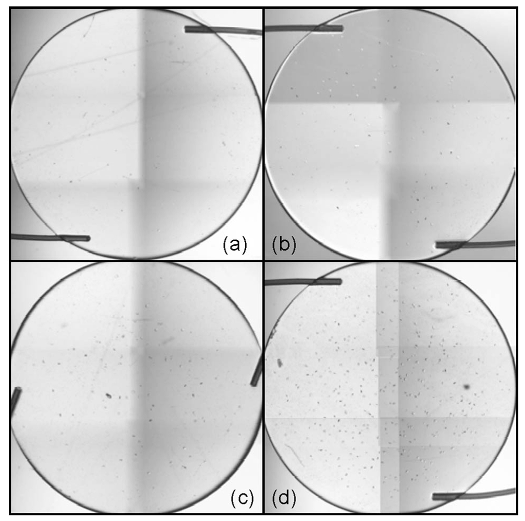
Microscopic images of different IOLs: (a) IOL #8 (manufacturer grade 1), (b) IOL #5 (manufacturer grade 2), (c) IOL #3 (manufacturer grade 3), and (d) IOL #1 (manufacturer grade 4).
As discussed in the Introduction, a standardized classification system for the glistenings has not yet been established. However, Waite, et al. [15] suggested a reasonable method to quantitatively grade IOLs for glistenings. This method is based on a digital imaging technique that counts the number of microvacuoles in the IOLs in the central region within a 2 mm × 2 mm area. Their work proposed to grade IOLs based upon severity index, which is the number of vacuoles in the IOLs under observation. We assumed a constant value of density per area for the entire area of an IOL. Thus, the number of vacuoles in the central 2 mm × 2 mm area of our IOL samples was calculated from the total number of vacuoles for the entire IOL by multiplying the ratio between the central area (4 mm2) and the area of a 6 mm diameter IOL (π × 32 mm2). The results are summarized in Table 1. While the manufacturer’s grading method is not known, our observation confirms that different grading methods produce different results. Since the vacuole counting method is most straightforward, we assumed this method to be the most accurate.
Table 1.
Summary of IOL Samples
| Lens | Manufacturer’s Grade | Number of Vacuoles in Central Area | Ref [11] method |
|---|---|---|---|
| #1 | 4 | 98.4 | 2 |
| #2 | 4 | 87.5 | 2 |
| #3 | 3 | 25.1 | 1 |
| #4 | 3 | 25.6 | 1 |
| #5 | 2 | 12.9 | 1 |
| #6 | 2 | 24.5 | 1 |
| #7 | 1 | 10.9 | 1 |
| #8 | 1 | 8.54 | 1 |
Although the method previously tested is straight-forward and accurate, it is practically impossible to count all the vacuoles from the total volume of an IOL, especially when the vacuole density is high. Thus, we tested a method that measures the scattered light intensity using an integrating sphere, as shown in Fig. 2. In our experimental setup, we utilized a laser beam (Melles Griot 658 nm diode laser) collimated by a simple fiber-optic arrangement consisting of a single-mode fiber that converts the output emission of the intensity-stabilized continuous-wave laser into a precisely collimated Gaussian 3 mm diameter laser beam. The IOL sample is placed in a balanced salt solution using a thin glass/quartz cuvette (1–2 mm optical path) in accordance with the International Standard published by ISO (ISO-11979-2). The cuvette holding the IOL is mounted directly against the input aperture of the integrating sphere. The collimated laser beam is precisely centered on the IOL, and then passes through the test IOL and into the integrating sphere. The diameter of the integrating sphere was 4.5 cm. The diameters of the three ports were 10 mm, 6 mm, and 6 mm for input port, output port and detector port, respectively. A silicon detector (DET) was placed at the detector port to measure the intensity of the radiation collected by the integrating sphere. The output port was configured in one of two arrangements. In arrangement 1, the port was blocked with a plug to allow the sphere to capture all of the transmitted light, both direct and scattered, passing through the IOL. This value, transmission (T), was recorded by the DET. In arrangement 2, the plug was removed from the output port to allow the direct light to pass out of the sphere. The detector therefore measured only the scattered light (S) from the lens. Multiple measurements were taken in this manner of each test lens and the results were averaged.
Degree of scattering (DS) was determined following the method presented by Oshika [11]:
| (1) |
The DS for lenses #1–#8 are shown in Table 2. In general, the DS increased as the lens grade increased. Oshika’s results show that grade 2 lenses had 2% higher DS than grade 1 lenses; thus, our samples were graded 1 and 2 for DS values up to 2% and 4%, respectively. The results are summarized in Table 2. Although the results are reasonable, samples #2 and #3 produced an error in grading when the integrating sphere was used. Also, samples #4 and #6 have similar numbers of vacuoles as #3. However, both were graded lower than #3. Since we assumed that the grading based on the number of vacuoles is the gold standard, we also assumed that the results obtained with the integrating sphere contained errors. The most probable reason for errors is the focal length effect, as explained in the previous section. As can be seen in Table 2, the focal lengths of samples #3, #4, and #6 are significantly larger than that of sample #2. The scattered light captured by the integrating sphere can produce a significantly different value when the same integrating sphere is used for different IOLs. When the focal length effect is eliminated, samples #1 and #2 should be in the same grade, and samples #3, #4, and #6 should also be in the same grade. However, the grade for samples #3, #4, and #6 should be lower than that of #1 and #2.
Table 2.
Summary of Results Using Integrating-Sphere Method
| Lens | Grade by Digital Microscopy | Focal Length (mm) | Degree Scattering, DS (%) | Grade by Integrating Sphere |
|---|---|---|---|---|
| #1 | 2 | 41.5 | 3.72 | 2 |
| #2 | 2 | 41.4 | 1.88 | 1 |
| #3 | 1 | 47.8 | 2.86 | 2 |
| #4 | 1 | 48.4 | 1.58 | 1 |
| #5 | 1 | 53.3 | 1.08 | 1 |
| #6 | 1 | 56.8 | 1.32 | 1 |
| #7 | 1 | 40.6 | 0.58 | 1 |
| #8 | 1 | 41.2 | 0.33 | 1 |
We then tested the BRIM, shown in Fig. 3. The diameter of the integrating sphere used for this new method was 8.7 cm, which is larger than the longest focal length of the IOL samples for testing. To capture and remove the ballistic photons, we initially tested the BRIM approach using either a 600 μm core diameter multimode optical fiber or a 1 mm core diameter silver-coated hollow-core fiber at the output port. However, these arrangements proved not to be acceptable due to the strong dependence of the laser-to-fiber coupling efficiencies related to the beam focal spot size, as well as to significant light leakage through the fiber coatings introducing errors. Therefore, these fibers were replaced with a stainless steel tube having a 1.4 mm inner diameter and a 1.8 mm outer diameter. It should be noted that any tube constructed with thin and nontransparent material can be used. Key requirements include the need for the inner diameter of the tube to be larger than the IOL focal spot and the thickness of the tube needs to be sufficiently thick to ensure that there is no light leakage out of the tube. In order to ensure the complete removal of ballistic photons, the intensity at the DET needs to be minimized by adjusting the position of the tube inside the integrating sphere. This is accomplished by placing the tube into the integrating sphere, as shown in Fig. 3. The tube is rigidly mounted such that the tube axis is collinear with and centered on the input port of the sphere. The tube is then moved along its main axis so that the tip of the tube is placed approximately at the focal spot of the IOL. The position of the tube is then finely adjusted so that the intensity at the bottom detector is minimized. This assures that the maximum number of ballistic photons are captured by the tube and conducted outside the sphere.
The normalized scattering (NS) is given by Eq. (2):
| (2) |
where is the scattered intensity measured by DET and is the transmitted laser intensity measured at close proximity behind the IOL. We selected a reasonable background and then established the grading criteria of NS for grade 1 and 2 as 4.00–10.00 and 10.01–20.00, respectively. The results are summarized in Table 3. These results match well with the grades obtained by the microscopy method. In addition, the BRIM resulted in the same grade for samples #1 and #2. Samples #1 and #2 have almost the same focal length and the highest count of vacuoles. Thus, these two samples should be graded higher than the others. Also, samples #3, #4, and #6 should produce similar grading results because they have a similar numbers of vacuoles. The BRIM showed that samples #3, #4, and #6 are graded identically, and lower than #2.
Table 3.
Summary of Results Using BRIM
| Lens | Number of Vacuoles in Central Area | NS (uW/mW) | Grade by BRIM |
|---|---|---|---|
| #1 | 98.4 | 10.2 | 2 |
| #2 | 87.5 | 11.2 | 2 |
| #3 | 25.1 | 8.80 | 1 |
| #4 | 25.6 | 7.28 | 1 |
| #5 | 12.9 | 5.13 | 1 |
| #6 | 24.5 | 6.78 | 1 |
| #7 | 10.9 | 5.42 | 1 |
| #8 | 8.54 | 4.54 | 1 |
5. Discussion
The grading method based on counting the number of vacuoles is most accurate. However, it is practically impossible to count all the vacuoles in an IOL if the number of vacuoles becomes excessively large. Although, the integrating-sphere method has some advantages over the vacuole-counting method in terms of providing a simpler and faster experimental grading procedure, to achieve high measurement accuracy the diameter of the integrating sphere should be similar to the IOL focal length. It is practically impossible, however, to have multiple integrating spheres with different diameters and large output apertures in order to capture all the ballistic photons from IOLs with different focal lengths. We improved the integrating-sphere method by incorporating a simple ballistic-photon removal mechanism. This new method (BRIM) significantly reduces the potential measurement error associated with different focal length IOLs. We repeated the measurements multiple times with consistent results and minimal time required for each measurement. This single experimental setup can be used for any IOL with positive dioptric power. The BRIM demonstrated that it can distinguish between IOLs with only slightly different numbers of vacuoles, while the simple integrating-sphere method without removal of the ballistic photons produced errors due to the effects of focal length. All measurements were performed using a single experimental setup. The proposed method can be employed for grading glistenings in IOLs with high accuracy regardless of the IOL focal lengths.
Despite the features described, two major problems remain with the BRIM. First, the method cannot distinguish scattering from vacuoles or from any other forms of scattering centers. Some internal impurities in the IOLs, dust in the IOL holder, or any other source of light scattering can affect the final measurement. These factors can lead to errors in the grading. This is not a problem if glistenings are defined to include any scattering from the IOLs. Second, the grading criteria cannot have statistical significance without measuring a significant number of IOL samples. To establish generally applicable grading criteria, perfectly clean IOLs (without glistenings) and IOLs with excessive numbers of vacuoles (e.g., grade 4 IOLs) should be measured to set the lower and upper threshold for grade 1 and grade 3.
Our future work is directed toward establishing universally applicable grading criteria with different measurement setups using the BRIM. Standardized specifications of the integrating sphere, such as the size of the apertures, losses within the integrating sphere, and diameter of the sphere, will be determined.
6. Conclusion
We developed a novel measurement method for quantifying glistenings in IOLs. The method is based on a light scattering measurement using an integrating sphere with a mechanism to remove ballistic photons from the integrating sphere. We established the robustness of the method using Zemax ray-tracing simulations. This method is called BRIM. We established a grading criteria using the number of vacuoles counted from digital microscope images. The IOL grading determined by the BRIM method compared favorably with the grading criteria established by counting the vacuoles from the digital microscope images. Ballistic-photon removal increased the measurement accuracy by minimizing the error from the effects of focal length. BRIM can distinguish slight differences in the number of vacuoles, while the integrating-sphere method without removal of the ballistic photons produced errors. Several different ballistic-photon removing methods were tested, and the use of a metal tube generated the most reliable measurement data. We believe that BRIM will provide a quantitative simple and cost-effective in vitro laboratory method for accurate and objective grading of glistenings in various IOL designs and materials, regardless of their dioptric powers. Further, we believe that the BRIM method may have more general applicability for the measurement of scattering in other optical elements, especially when the scattering is at a low level, such as that found in grades 1 and 2 IOLs.
Footnotes
Disclaimer: The mention of commercial products, their sources, or their use in connection with material reported herein is not to be construed as either an actual or implied endorsement of such products by the Department of Health and Human Services.
References
- 1.Ballin N, “Glistenings in injection-molded lens,” J. Am. IntraOcul. Implant Soc 10, 473 (1984). [DOI] [PubMed] [Google Scholar]
- 2.Klos KM, Richter R, Schnaudigel OE, and Ohrloff C, “Image analysis of implanted rigid and foldable intraocular lenses in human eyes using Scheimpflug photography,” Ophthalmic Res. 31, 130–133 (1999). [DOI] [PubMed] [Google Scholar]
- 3.Werner L, “Glistenings and surface light scattering in intraocular lenses,” J. Cataract Refract. Surg 36, 1398–1420 (2010). [DOI] [PubMed] [Google Scholar]
- 4.Tognetto D, Toto L, Sanguinetti G, and Ravalico G, “Glistenings in foldable intraocular lenses,” J. Cataract Refract. Surg 28, 1211–1216 (2002). [DOI] [PubMed] [Google Scholar]
- 5.Ayaki M, Nishihara H, Yaguchi S, and Koide R, “Surfactant induced glistenings: surface active ingredients in ophthalmic solutions may enhance water entry into the voids of implanted acrylic intraocular lenses,” J. Long-term Eff. Med. Implants 16, 451–457 (2006). [DOI] [PubMed] [Google Scholar]
- 6.Arshinoff S, “Does a tight capsular bag cause glistenings?,” J. Cataract Refract. Surg 24, 6 (1998). [DOI] [PubMed] [Google Scholar]
- 7.Dick HB, Olson RJ, Augustin AJ, Schwenn O, Magdowski G, and Pfeiffer N, “Vacuoles in the AcrySof_intraocular lens as factor of the presence of serum in aqueous humor,” Ophthal. Res 33, 61–67 (2001). [DOI] [PubMed] [Google Scholar]
- 8.Gregori NZ, Spencer TS, Mamalis N, and Olson RJ, “In vitro comparison of glistening formation among hydrophobic acrylic intraocular lenses,” J. Cataract Refract. Surg 28, 1262–1268 (2002). [DOI] [PubMed] [Google Scholar]
- 9.Dhaliwal DK, Mamalis N, Olson RJ, Crandall AS, Zimmerman P, Alldredge OC, Durcan FJ, and Omar O, “Visual significance of glistenings seen in the AcrySof intraocular lens,” J. Cataract Refract. Surg 22, 452–457 (1996). [DOI] [PubMed] [Google Scholar]
- 10.Christiansen G, Durcan FJ, Olson RJ, and Christiansen K, “Glistenings in the AcrySof intraocular lens: pilot study,” J. Cataract Refract. Surg 27, 728–733 (2001). [DOI] [PubMed] [Google Scholar]
- 11.Oshika T, Shiokawa Y, Amano S, and Mitomo K, “Influence of glistenings on the optical quality of acrylic foldable intraocular lens,” Br. J. Ophthalmol 85, 1034–1037 (2001). [DOI] [PMC free article] [PubMed] [Google Scholar]
- 12.Gunenc U, Oner FH, Tongal S, and Ferliel M, “Effects on visual function of glistenings and folding marks in AcrySof intraocular lenses,” J. Cataract Refract. Surg 27, 1611–1614 (2001). [DOI] [PubMed] [Google Scholar]
- 13.Cisneros-Lanuza A, Hurtado-Sarrio M, Duch-Samper A, Gallego-Pinazo R, and Menezo-Rozale JL, “Glistenings in the Artiflex phakic intraocular lens,” J. Cataract Refract. Surg 33, 1405–1408 (2007). [DOI] [PubMed] [Google Scholar]
- 14.Wilkins E and Olson RJ, “Glistenings with long-term follow-up of the Surgidev B20/20 polymethylmethacrylate intraocular lens,” Am. J. Ophthalmol 132, 783–785 (2001). [DOI] [PubMed] [Google Scholar]
- 15.Waite A, Faulkner N, and Olson RJ, “Glistenings in the single-piece, hydrophobic, acrylic intraocular lenses,” Am. J. Ophthalmol 144, 143–144 (2007). [DOI] [PubMed] [Google Scholar]
- 16.Behndig A and Monestam E, “Quantification of glistenings in intraocular lenses using Scheimpflug photography,” J. Cataract Refract. Surg 35, 14–17 (2009). [DOI] [PubMed] [Google Scholar]
- 17.Mackool RJ and Colin J, “Limitations of Scheimpflug photography in quantifying glistenings,” J. Cataract Refract. Surg 35, 1480–1481 (2009). [DOI] [PubMed] [Google Scholar]