

Abstract
In 2022, the occupation of firefighting was categorized as a “Group 1” carcinogen, meaning it is known to be carcinogenic to humans. The personal protective equipment that structural firefighters wear is designed to safeguard them from thermal, physical, and chemical hazards while maintaining thermo-physiological comfort. Typically, the outer layer of structural turnout gear is finished with a durable water and oil-repellent (DWR) based on per- and polyfluoroalkyl substances (PFAS) that helps limit exposure to water and hazardous liquids. The PFAS-based aqueous emulsion typically used in DWR finishes is highly persistent and can cause various health problems if absorbed into the body through ingestion, inhalation, and/or dermal absorption. In response, the U.S. Fire Service has begun using non-PFAS water repellants in firefighter turnout gear. This study aims to evaluate the performance of both traditional PFAS-based and alternative non-PFAS outer shell materials. The study involved exposing both PFAS-based and non-PFAS DWR outer shell materials in turnout composites to simulated job exposures (i.e., weathering, thermal exposure, and laundering) that artificially aged the materials. After exposures, samples were evaluated for repellency, durability, thermal protection, and surface chemistry analysis to determine any potential performance trade-offs that may exist. Non-PFAS outer shell fabrics were found not to be diesel/oil-repellent, posing a potential flammability hazard if exposed to diesel and subsequent flame on an emergency response. Both PFAS-based and non-PFAS sets of fabrics performed similarly in terms of thermal protective performance, tearing strength, and water repellency. The surface analysis suggests that both PFAS and non-PFAS chemistries can degrade and shed from fabrics during the aging process. The study indicates that firefighters should be educated and trained regarding the potential performance trade-offs, such as oil absorption and flammability concerns when transitioning to non-PFAS outer shell materials.
Keywords: Firefighters, turnout gear, outer shell, PFAS, DWR, Aging
Introduction
Firefighting is one of the most dangerous occupations due to the involved duties, responsibilities, and hazards.1–3 Heavy-duty personal protective equipment (PPE) is required by the firefighters to safely and efficiently handle the responsibilities that come with this profession.4 The PPE worn by the firefighters includes turnout jackets and pants, gloves, boots, helmets, hoods, and self-contained breathing apparatus. This PPE is designed to protect firefighters against different hazards (i.e., thermal, physiological, physical, chemical, and biological) that they may be exposed to while performing their duties.4,5 Firefighters can be exposed to combustion products from fires (e.g., polycyclic aromatic hydrocarbons and particulates), building materials (e.g., asbestos), firefighting foams (e.g., per- and polyfluoroalkyl substances (PFAS)), flame retardants, diesel exhaust, and other hazards.6–11 The structural turnout ensemble worn by firefighters principally consists of three layers; outer shell, moisture barrier, and thermal liner, all of which are standardized by the National Fire Protection Association (NFPA) 1971: Standard on Protective Ensembles for Structural Fire Fighting and Proximity Fire Fighting.12 The outer shell protects the wearer from thermal and physical hazards and is typically made of inherently flame-resistant fibers i.e., polybenzimidazole (PBI), meta-aramid, para-aramid, or poly-benzoxazole (PBO), with a ripstop, plain-weave, or twill fabric structures.2,13,14 The outer shell is usually finished with a PFAS-based durable water and oil-repellent (DWR) or alternative non-PFAS water repellent finish to protect the wearers against hazardous liquids (Figure 1).15,16 These finishes also prevent the turnout gear from becoming to getting soaked with water and oils which can add substantial weight and increase physiological burden.17 Repellent properties are crucial for protecting against hazardous liquids, especially in extreme environmental conditions encountered while firefighting.18 Aqueous emulsions based on PFAS have typically been used as the finishing chemicals that impart both water and oil repellency. Alternative non-PFAS DWR finishes are also available, which include, but are not limited to, hydrocarbon-wax and silicone-based polymers.16 Moisture barrier is an essential component of turnout gear due to its dual role in preventing water from penetrating through while allowing moisture vapor to pass through, providing thermo-physiological comfort.19 Expanded polytetra-fluoroethylene (e-PTFE) barriers are typically used, which are usually laminated on a meta-aramid fabric.20–22 The fabric side of the barrier is also typically coated with a DWR to ensure the highest repellency. The thermal liner provides most of the thermal protection. Approximately 75% of the total thermal protection is provided by moisture barrier and thermal liner. Typically a non-woven batting quilted on a thin woven fabric is used as thermal liner. High performance fibers such as para-aramid, meta-aramid, PBI and PBO are used in both layers.22,23
Figure 1.
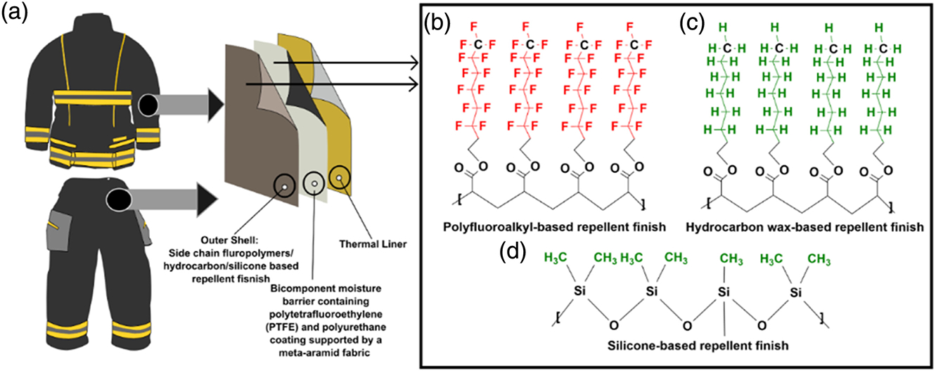
Examples of a structural turnout gear; (a) three layers of structural turnout gear (i.e., outer shell, moisture barrier, and thermal liner); commonly applied DWR chemistries on outer shell fabrics; (b) polyfluoroalkyl, (c) hydrocarbon, (d) silicone-based DWR chemistries.
The usage of PFAS has grown immensely across multiple industries since their invention in the 1950s due to their exceptional stain- and water-repellent properties in addition to their thermal stability and overall chemical resistance. PFAS are widely used in many applications including food packaging, cookware, electronics, medical products, carpeting, cosmetics, building materials, and apparel among countless others.24 In the textile industry, fabrics, including turnout gear outer shells, have been historically finished with side chain fluoropolymers, one sub-category of PFAS, due to their high level of repellency to water and oils and durability.17 PFAS use in turnout gear outer shell fabrics imparts very high levels of hydrophobicity and oleophobicity due to the lower surface tension provided by the fluoromethyl (-CF3) end groups of the side chains.25 The wetting behavior of the fabrics depends on the adhesive interaction between the solid and liquid surfaces, as well as the air interface.18 The fabrics coated with a side chain fluorinated polymer with a -CF3 end group have a surface tension of approximately 6 dyne/cm at 20°C, which will repel any liquids with higher surface tension (e.g., water has a surface tension of 73 dyne/cm at 20°C, octane has a surface tension of 22 dyne/cm at 20°C).15,18,26 The -CH3 terminal group (hydrocarbon and silicone-based polymer) has a surface tension of approximately 22 dyne/cm.16 The surface tensions of most oils (i.e., diesel fuel, gasoline, hydraulic fluid, etc.) are below 15 dyne/cm. Therefore, to effectively repel lower surface tension liquids, PFAS-based finishes are required for fabrics. These oils may be present in the fire scene, especially during car accidents, auto body shop fires, etc. Therefore, having no resistance to oils may increase thermal or flashfire hazards if the gear is exposed to oils at the fire scene.
PFAS are a significant concern for the environment and human health due to their toxicity, persistence, and bioaccumulation.9,16,27–29 The general population is exposed to PFAS through contaminated food, drinking water, cookware, indoor dust, and ambient air.30–33 Added exposures to PFAS are relevant to firefighters since these chemicals are used in turnout gear as DWRs and in aqueous film-forming foams (AFFF) that are used to extinguish fires based on fuel and oils.16,34–36 Studies have reported links between perfluorooctanoic acid (PFOA) with certain types of cancer such as prostate, testicular, mesothelioma, and non-Hodgkin’s lymphoma, which are four of the top eight cancers that firefighters have increased risks for.37–40 Several studies reported an elevated risk of cancer in firefighters compared to the general population.9,40–42 The International Agency for Research on Cancer (IARC) also re-classified the firefighting occupation as a “Group 1” carcinogen in 2022, defining firefighting as a known carcinogen to humans.6 Therefore, firefighters’ exposure to PFAS and associated health risks are relevant when discussing occupational cancer. Furthermore, studies have reported PFAS emission from outdoor apparel as well as from the outer shell fabrics of turnout gear treated with PFAS-based DWR finish in both new and aged conditions.17,34,35,43–46 Since turnout gear could be a potential exposure source of PFAS, manufacturers of firefighter PPE have introduced non-PFAS (defined as finishes with no PFAS chemistry intentionally added including hydrocarbon or silicone-based finishes) outer shell materials for their turnout gear, which are expected to only be repellent to water but not to oils and fuels.
As the U.S. firefighting community continues moving towards non-PFAS turnout gear, the potential trade-offs that may exist between the PFAS and non-PFAS turnout gear materials must be explored to ensure no unintended consequences are experienced. Understanding the potential limitations of non-PFAS turnout gear will prepare firefighters for unforeseen situations and possible injuries that may be due to the presence of any potential performance trade-offs to which they have not historically been accustomed to. In addition, it is also worthwhile to know the performance trade-offs of the legacy and newer turnout gear materials in both new and aged conditions. A significant number of studies reported the performance such as tensile/tearing strength,47–50 thermal protective performance,14,51 shrinkage,52 chemical permeation,53 etc., of turnout gear materials in new and simulated aged conditions. However, only a few recent studies investigated the performance trade-offs between the PFAS and non-PFAS DWR finished fabrics used in outdoor apparel.18,43,44,54 As of the completion of this work, no study has been found investigating the performance comparison between the PFAS and non-PFAS fabrics used in firefighter turnout gear.
In this research, turnout composites of different repellent finishes were subjected to cycles of ultraviolet light and weathering, thermal exposures, and laundering to simulate on-the-job exposures of the materials. Following the simulated exposures, the materials were evaluated for trade-offs that may exist between PFAS and non-PFAS repellent finishes. The evaluations included the ability to resist liquid contamination (i.e., water and diesel fuel via contact angle, and liquid splash testing), tearing strength, thermal protective performance (TPP), and analysis of fabric surfaces, which includes digital microscopy imaging and 2D mapping by Time-of-Flight Secondary Ion Mass Spectrometry (ToF-SIMS) and X-ray Photoelectron Spectroscopy (XPS) spectra of chemical analysis.
Materials
The three layers of fabrics (i.e., outer shell, moisture barrier, and thermal liner) used in structural firefighter turnout gear were included in this study. This study used one type of outer shell fabric of 80% meta/para-aramid spun yarns and 20% 400 denier para-aramid filament. The overall blend of the fabric was 35% meta-aramid and 65% para-aramid. The fabric weave was a 2 × 1 Z twill with filament twill technology with 60 × 60 ends per inch × picks per inch. An unfinished fabric (Fabric A) which was only manufacturer pre-scoured was used as a control. Two different types of PFAS-based (Fabrics B and C) and two different types of non-PFAS finished fabrics (Fabric D (silicone) and E (hydrocarbon-wax)) were used. Fabrics A, B, D, and E were readily available from a manufacturer, while Fabric C was finished in our facilities by treating the unfinished fabric (Fabric A) with a cationic six-carbon PFAS-based DWR (UNIDYNE™ TG-5610). Since the focus of this study was on the outer shell finishes, only one type of commercially available bicomponent moisture barrier with ePTFE and a polyurethane coating was used in the fabric composite. The ePTFE coating was laminated on an aramid fabric which had a PFAS-based DWR finish applied. Similarly, only one type of thermal liner was used. The thermal liner was quilted to two layers of fabric with fabric weights of 2.3 oz./yd2 and 1.5 oz./yd2. The fiber content of the face cloth was 60% meta-aramid filament yarns and 40% meta-aramid/Lenzing FR (flame retardant) spun yarns. The multi-exposure aging process was done on the three layers together to simulate the actual usage scenario. The properties of these fabrics are listed in Table 1.
Table 1.
Specification of the fabrics used in the study.
| Fabric layer | Fabric code | DWR chemistry | Fiber content | Nominal weight | Color |
|---|---|---|---|---|---|
|
| |||||
| Outer shell | Fabric A Fabric B Fabric C |
Unfinished Six-carbon-based PFAS Six-carbon-based cationic PFAS (finished in the textile lab) |
35% meta-aramid and 65% para-aramid | 6.5 oz/yd2 (220 g/m2) | Khaki |
| Fabric D Fabric E |
Silicone (non-PFAS) Hydrocarbon (non-PFAS) | Black | |||
| Inner layers | |||||
| Moisture barrier | Fabric F | Fluorinated finish on the fabric layer | Bicomponent barrier containing ePTFE and polyurethane laminated on a meta-aramid fabric | 4.7 oz/yd2 (160 g/m2) | Off-white/black |
| Thermal liner | Fabric G | No finishes | 60% meta-aramid filament yarns and 40% meta- aramid spun yarns | 7.4 oz/yd2 (250 g/m2) | Ice blue/gold |
Methods
Finishing of the materials
Fabric A (unfinished) was chemically finished with a cationic six-carbon based PFAS (cationic C6) finishing at a textile dyeing and finishing laboratory and coded as Fabric C. Three replicates were prepared for the cationic C6 finish. The padding solution was prepared with a concentration of 80 g/L UNIDYNE™ TG-5610 and 10 g/L of acetic acid. The UNIDYNE™ TG-5610 is built on C6 technology and possesses a cationic ionic character. To achieve maximum water and oil repellency, it is recommended to maintain the bath’s pH between 4 and 5. Acetic acid was used to keep the bath’s pH below 5. The fabric was passed through the padding mangle and ensured 80% wet pick up. The fabric was then cured in an oven for 2 minutes at 180°C temperature. The six-carbon-based conventional PFAS (C6) finish, silicone, and hydrocarbon-based repellent finished fabrics were directly procured from the manufacturer.
Sample preparation
Fabric composites replicating the three-layered clothing system (outer shell, moisture barrier, and thermal liner) typically used in structural firefighter turnout gear were used in this study. The thermal liner and moisture barrier were stitched together. Snap buttons were used to attach the outer shell material to the inner layers (Figure 2). This facilitated the attachment and detachment of the outer shell with/from the inner layers. The samples were exposed in the Atlas Ci-5000 weather-ometer and in a thermal oven as composites. The outer shell fabrics were washed separately from the inner layers, following the manufacturer’s recommendations, since their washing processes are different from each other according to the NFPA 1851: Standard on Selection, Care, and Maintenance of Protective Ensembles for Structural Fire Fighting and Proximity Fire Fighting (2020 edition).
Figure 2.
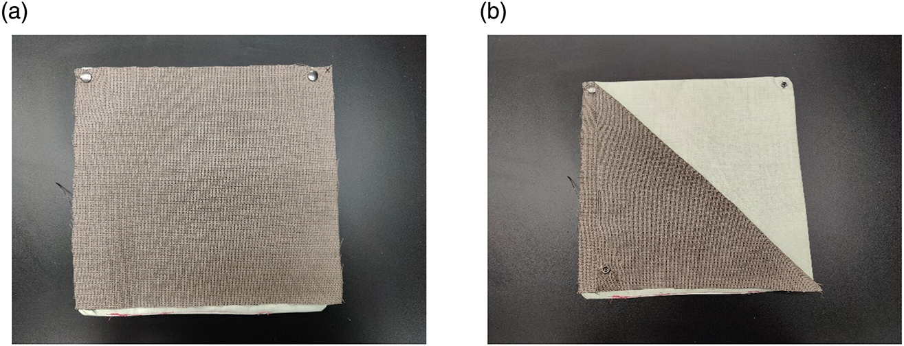
Three-layered composites for the aging process: (a) outer shell fabric is attached with inner layers with snap buttons, (b) outer shell can be detached from the inner layers for washing separately.
Aging process
Three different aging processes were used in a specific sequence to age the composites. The aging process was done sequentially using three aging types: (1) UV weathering, (2) thermal exposure, and (3) laundering. Aging process approaches and parameters were selected to mimic the types of environmental conditions to which firefighting protective garments can be exposed over the first few years of typical service life. It is recognized that these conditions can vary significantly for different fire departments and firefighters and that multiple other conditions (such as abrasion, flexing, chemical, and particulate exposure) can apply.
Weathering.
AATCC test method 169–2017: Weather Resistance of Textiles: Xenon Lamp Exposure was utilized to expose fabrics to UV radiation, heat, and water to simulate the weathering effects in end-use environments. Fabrics (46 cm × 46 cm) were exposed in a Weather-Ometer (Atlas Ci5000) which applied heat, moisture, and UV light at different intensities and temperatures (Figure 3). The total time of UV exposure was 60 hours in two cycles (30 hours each). Exposures followed a modified version of option two of UV exposure parameters as per the AATCC 169–2020 subsection 7.2. The parameters applied for the UV exposure were as follows: 120 min cycle, 60 min light only, 70 ± 5% RH, alternating with 60 min dark, black panel temperature 77 ± 3°C (170 ± 5°F) during the light cycle, and 50 ± 3°C (122 ± 5°F) during the dark cycle, with no water spray.
Figure 3.

Exposing fabrics in the Atlas weather-ometer Ci-5000.
Thermal exposure.
Thermal aging is often performed as a precondition for evaluating fabric properties in NFPA 1971 where fabric samples are suspended in an oven at the selected temperature. For this study, a one-sided heat aging approach was used that involved conducting the thermal exposure in the Brown Manufacturing FireFly™ Curing Oven at a temperature of 180°C (356°F) temperature (Figure 4) on the fabrics (46 cm × 46 cm). The fabric composites were laid on the oven’s conveyor belt with the outer shell facing up toward the heating elements. The exposure time for each specimen was 10 minutes in each round. The total number of exposure rounds was a six-in-one cycle, so fabrics were exposed for 60 minutes in one cycle and 120 minutes in the two cycles. This oven applies heat on the fabric surface through eight heating coils. Temperatures at nine different partitions were continuously monitored as specimens were transported through the oven by its conveyor belt.
Figure 4.
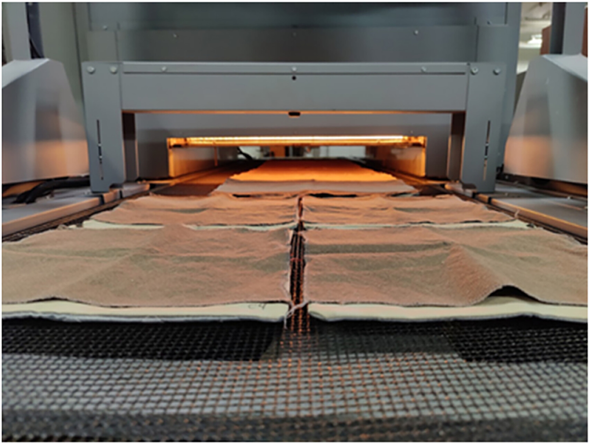
Fabrics composites being exposed in the curing oven at 180°C temperature.
Laundering.
In total, 24 washes were conducted in two cycles. Twelve washes were done after each UVand thermal exposure cycle. Fabrics were air-dried for 24 hours after every four washes. Washing was done according to the NFPA 1851 (2020 edition) standard in a hardmount front-loading washer extractor. This wash formulation entails set prewash, fill, flush, agitate, rinse, drain, and extraction operations where the length of time, temperature, and water level are established for the individual steps. There were slight differences in the formulations applied to shell materials versus liner materials. The manufacturer’s recommendation was followed, wherein the maximum water temperature was set to 40°C (105°F) for 18 minutes, followed by several rinse cycles using cold water, resulting in a total wash duration of 60 minutes. CITROSQUEEZE® PPE & turnout gear cleaner surfactant was used during each wash cycle. CITROSQUEEZE® contains the following ingredients: water (60%–90%), food grade D-limonene (5%–20%), Non-ionic surfactant (1%–10%), Mackamide C (1%–10%), Glycol Ether EB (1%–10%). The recommended amount was 180 mL (6 oz.) for a 45-lbs load. The total load used was 30 lbs. including the fabric samples along with additional ballast material. Therefore, 120 mL of detergent was used during each wash cycle.
Evaluation methods
Contact angle measurement.
The contact angle of water and diesel fuel against samples in both new and aged conditions was measured using the Goniometer FDS Corporation Data Physics OCA system. The shape and size of the testing samples were circular and 1 cm in diameter. Each sample had three replicates (n = 3). The average contact angle was calculated from three data points for each sample. The contact angle of liquids on the fabric surface can be used to classify the wetting behavior of fabrics semi-quantitatively. A contact angle above 90° to the fabric surface is typically considered hydrophobic, whereas below 90° is typically considered hydrophilic. The contact angle can be a good measure to study the durability of the finishes after aging.
Splash test with water and diesel.
The ISO 6530:2005: Protective clothing — Protection against liquid chemicals Test method for resistance of materials to penetration by liquids was used to measure the fabrics’ repellency. The materials were exposed to water and diesel fuel to assess water and oil repellency. Three test specimens (n = 3) from each outer shell material were sprayed with 10 mL of either water or diesel for 1 minute. Following the exposure, all materials were weighed to determine the amount of the applied liquid absorbed by the material, the amount that penetrated through the material, and the amount that the material repelled. The sample size mentioned in the standard is 36 cm × 23.5 cm. However, the sample size was reduced to 30 cm × 7.5 cm to match the sampling requirements for performing subsequent tests on the vertical flame tester. Samples were tested for repellency as composites. That means the outer shell, followed by the moisture barrier and thermal liner, was set on the gutter of the splash test instrument with the outer shell facing the spray. Blotter paper was placed beneath the thermal liner to absorb any liquid that penetrated the composite sample. The amount of liquid absorbed onto the moisture barrier (penetrated through the outer shell) was defined as penetration 1 (P1). The amount of fluid absorbed onto the paper film (penetrated through the moisture barrier and thermal liner) was defined as penetration 2 (P2). Even though splashed water or diesel was able to absorb onto the moisture barrier by penetrating the outer shell, no liquid passed through the moisture barrier and thermal liner onto the paper film. Therefore, only the values of P1 are presented in this article and denoted as the penetration index.
Vertical flame test.
Diesel fuel-splashed samples were dried for 24 hours inside a chemical hood before being tested for their flame resistance. ASTM D6413M-15: Standard Test Method for Flame Resistance of Textiles (Vertical Test), commonly referred to as the vertical flame test, exposes a 30 cm × 7.5 cm sample of the material to a 3.8 cm tall flame from a Bunsen burner. Samples were exposed to flame for 3 seconds. Once the flame was removed from under the pieces, the after-flame time was measured. In NFPA 1971 (2018), an acceptable after-flame time is 2.0 seconds or less. NFPA requires twelve seconds of flame exposure for the unexposed samples and 3 seconds for the exposed samples. However, for our testing, we kept the flame exposure time at 3 seconds for both cases.
Thermal protective performance.
Thermal protective performance was measured following NFPA 1971 (2018 edition) standard procedures (based on a modified form of ISO 17492: 2003). This standard was designed to measure the heat transfer performance of materials after exposure to combined convective and radiant thermal hazards reminiscent of flashovers. The TPP test was done on the three layers composite in contact configuration using a heat flux of 84 kW/m2 ± 2 kW/m2. Two gas burners with a diameter of 38 mm top and 1.2 mm orifice size were used as one of two thermal energy sources. The second thermal exposure source was nine 500 W T3 translucent quartz infrared lamps arranged in a linear array with 13 ± 0.5 mm spacing between the centers of each lamp and 125 ± 10 mm from the specimen surface. Three samples of 150 × 150 ± 5 mm specimens were prepared for testing for each testing scenario. The fabric with a higher TPP value implies a higher flame resistance and should provide more thermal protection to the wearer.
Trapezoid tearing strength test.
The trapezoid tearing strength test was measured as per ASTM D5587–15: Standard Test Method for Tearing Strength of Fabrics by Trapezoid Procedure using the Qtest five material testing system. The samples were conditioned for 24 hours before testing according to ASTM D1776–20: Standard Practice for Conditioning and Testing Textiles. Three specimens (n = 3) were prepared from each composite with dimensions of 15 cm × 7.5 cm. The longer sides of the samples were in the warp direction since the interest was to measure the strength of the warp yarn.
Surface analysis.
Digital microscopy images were obtained using a Keyence VHX7000 digital microscope at 100x magnification. ToF-SIMS and XPS were used for the analysis of the surface chemistry of the fabrics in both new and aged conditions. ToF-SIMS analysis was performed for surface imaging to provide spatially-resolved information about the surface of the samples. ToF-SIMS analysis was performed using a TOF.SIMS 5 (IONTOF, Münster, Germany) instrument. A 25 keV, 0.4 pA Bi3 + analytical beam was used for imaging and quantitative analysis. A 45° angle of incidence was used for the beam. The negative secondary ion mass spectra obtained were calibrated using C−, O−, OH−, and Cn−, respectively. The positive secondary ion mass spectra were calibrated using H+, C+, C2H3+, C3H5+, and C4H7+. However, ToF-SIMS analysis is generally considered a semi-quantitative technique, rather than a fully quantitative method. Therefore, to determine the elemental and chemical compositions, XPS analysis was also performed, a widely used and highly quantitative surface analysis technique. The surface compositions of “nitrogen (N), oxygen (O), Fluorine (F) and carbon ©” were characterized using XPS with an XPS/UVS-SPECS system featuring a PHOIBOS 150 analyzer under a pressure of approximately 3 × 10⁻¹⁰ mbar. The instrument utilized Mg Kα X-ray (hν = 1253.6 eV) and Al Kα X-ray (hν = 1486.7 eV) sources. The data were acquired using the Mg Kα X-ray source, which operated at 10 kV and 30 mA (300 W) and analyzed with the CasaXPS software. XPS spectra of the survey scan were recorded with a pass energy of 24 eV in a 0.5 eV step, and high-resolution scans were recorded with a pass energy of 20 eV in a 0.1 eV step. The C1s peak was used as an internal reference with a binding energy of 285 eV.
Results and discussion
Contact angle measurement
The water and diesel fuel contact angle data of all the fabrics in new and aged conditions are shown in Figure 5. The water contact angle of all the DWR finished fabrics was above 135° in new condition, which can be considered as a hydrophobic material. Although the contact angle of all DWR-finished fabrics decreased after the aging process, they were still above 110°. Fabric A (unfinished) showed some repellency in the new condition which was completely lost after the aging process. This could be due to the presence of sizing chemicals on the fabric surface, which are used during the weaving process to reduce the yarn breakage, which was eventually removed during the aging process. It might also involve the opening of fabric structure as a result of the aging process. The differences in the water contact angle between the PFAS and non-PFAS-treated fabrics did not appear significant in new conditions, as both the PFAS and non-PFAS finishes are good water repellents. However, the contact angle of Fabric C (PFAS-based DWR finished in the lab.), and Fabric E (hydrocarbon wax-based DWR) reduced notably compared to the other DWR-treated fabrics. The fabrics showed high repellency against water (above 90°), even after aging. In terms of water repellency, both the PFAS and non-PFAS-treated fabrics exhibited similar behaviors in both new and aged conditions.
Figure 5.
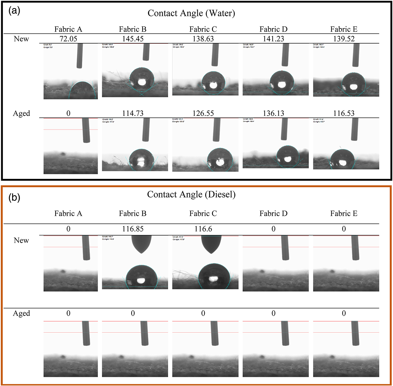
Contact angle test (a) water and (b) diesel against fabric surface: Water repellency performance of DWR-treated fabrics remained excellent under both new and aged conditions. Non-PFAS-based DWR-treated fabrics exhibited no repellency to diesel fuel, whereas PFAS-based DWR-treated fabrics initially displayed diesel repellency but readily absorbed the fuel after aging.
Fabric A (unfinished), and Fabrics D and E (non-PFAS finished fabrics) showed no contact angle when diesel fuel was used. Because diesel fuel has a low surface tension of approximately 18 dyne/cm, non-PFAS DWR chemistries were not able to repel it. Fabrics B and C (PFAS-based finishes) showed high diesel contact angles above 110° in the new condition, indicating diesel repellency. However, the contact angle of these fabrics decreased to zero degrees after the aging process. That suggests that PFAS finishes were degrading or disorienting during the aging process, therefore, both fabrics absorbed the applied diesel fuel instantly after applying it on the fabric surface. Although the new PFAS and non-PFAS finished fabrics behaved differently, all fabrics showed no diesel contact angle after the aging process. The impact on diesel fuel repellency was notably more significant compared to water repellency. This difference can be attributed to the inherent difficulty in repelling diesel fuel due to its low surface tension, and as a result, after the aging process, the fabrics failed to repel diesel fuel. All the experimental contact angle values are given in Table S1.
Splash test
In this research, the ISO 6530:2005 standard was used to measure the repellency, absorbency, and penetration index of various outer shell materials with different repellent finishes (unfinished, PFAS-based, and non-PFAS). The materials were exposed to water (72 dyne/cm) and diesel fuel (18 dyne/cm) to assess both water and oil repellency. Three test specimens (n = 3) from each outer shell material were splashed with 10 mL of either water or diesel fuel in 1 minute. The repellency, absorbency, and penetration index of the fabrics are given in Figure 6. The water repellency index of all four finished fabrics was more than 90% in the new condition. The absorbency of Fabrics B, C, and E was less than 1% in the new condition. Only Fabric D absorbed approximately 2% of splashed water. After the aging process, all four fabrics were still able to repel most of the water. The water repellency of all fabrics was still more than 95% even after aging except Fabric E. Fabric E repelled around 92% of water after the aging process which was around 99% in the new condition. All four finished fabrics repelled more than 90% water in both new and aged conditions, which also matched the contact angle data. Even though Fabric A was unfinished the repellency of the fabric was more than 90% in new condition with an absorbency index of around 8%. The repellency of the control fabric decreased to 63% after the aging process with a 27% absorption. This also correlated with the contact angle data which was 72° in new condition and reduced to 0° after the aging process. As mentioned before, this could be due to the presence of residual chemicals on the fabric surface from the manufacturing process, which were eventually removed during the aging process. It could also be the opening up of fabric construction due to the aging process. In terms of water repellency, all four DWR-finished fabrics showed excellent repellency to water in new and as well as in aged conditions. Therefore, it can be concluded that both the PFAS and non-PFAS DWR chemistries offer very good repellency to water. While some parts of the repellent finishes were washed off during the aging process, the fabrics were still able to repel water and retain excellent water repellency.
Figure 6.
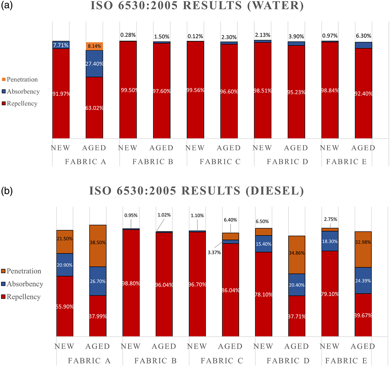
Splash test results for water and diesel; Figure (a) represents the splash test results for water, and (b) represents the splash test results for diesel; the red color of the bar represents the repellency index, the blue color represents the absorbency index and orange color represents the penetration index. PFAS-based DWR-treated fabrics demonstrated outstanding repellency to both water and diesel fuel, maintaining their performance in both new and aged conditions. In contrast, fabrics treated with non-PFAS DWR exhibited excellent water repellency but were less effective at repelling diesel fuel.
Diesel fuel, a liquid with lower surface tension than water is challenging to repel especially for repellants using non-PFAS chemistry. Both Fabrics B and C showed excellent resistance to diesel fuel, which was above 95% in the new condition. The diesel fuel repellency of Fabric B was above 95% even after the aging process. However, the repellency of Fabric C reduced to 86% after the aging process. Though both Fabrics B and C were based on the PFAS chemistries, Fabric C was finished in the textile lab., which may not be as optimized as Fabric B, which was commercially manufactured. Therefore, during the aging process more of the finish could have come off from Fabric C than Fabric B. Consequently, Fabric B was able to repel more diesel fuel after aging compared to Fabric C. Both the fabrics showed excellent resistance to absorbency and penetration as well. Though the diesel contact angle decreased to 0° for both fabrics after the aging process (Figure 5), the splash test results suggest that both fabrics were still able to repel most of the fuel. This could be due to the resistance to wicking of the fabric. Even though diesel drops were absorbed in Fabrics B and C after aging during the contact angle test, if there is not enough wicking, during the splash test a very small amount of diesel fuel will be absorbed by the fabrics. Moreover, the contact angle test involves applying a very small amount of liquid (5 to 8 μL) to the fabric, which may not be directly comparable to the larger liquid volume (10 mL) used in the splash test. Additionally, UV and thermal exposures were applied to one side of the fabric during the artificial aging process, potentially leading to the removal of the DWR finish from the exposed surface (see the surface analysis sub-section later in this section). It’s important to note that the loss of the DWR finish from the exposed surface does not necessarily imply uniform removal of finishes from the outer shell fabric throughout its entire thickness. In the splash test, where a larger liquid volume is employed, the overall presence of the DWR finish in the fabric throughout its thickness is crucial. Conversely, in the contact angle test, which utilizes a very small liquid volume, the result is predominantly influenced by the presence of the DWR finish on the surface. The splash test also holds the sample at a 45° angle which allows for liquids to run-off compared to the contact angle test which holds the sample horizontalally. This difference in orientation could provide further explanation as to the differences in the results of the two methods.
Non-PFAS DWR did not repel lowered surface tension liquids efficiently. The repellency to diesel fuel of Fabrics D and E was around 80% in new condition, which eventually decreased to around 40% after the aging process. With a decrease in repellency, the absorbency and penetration were significantly increased for Fabric D and E. The absorbency increased from 15% to 20% and 18% to 24% for Fabrics D and E, respectively, after the aging process. The penetration index of both fabrics increased considerably after aging. The penetration index of both fabrics was around 5% before aging, which increased to about 35% after the aging process. Penetration index indicates the amount of exposed diesel fuel that was absorbed onto the fabric side of the moisture barrier penetrating the outer shell. Fabric A, with no finishing, behaved almost similarly to Fabrics D and E. Therefore, it could be said that having a DWR finished based on non-PFAS chemistry will not impart any repellency to diesel fuel and similarly lower surface tension liquids. Significant differences were observed in terms of diesel repellency between the PFAS and non-PFAS-treated fabrics. If oil repellency is required in the job requirement there is still no other option other than PFAS-based DWR. The splash test suggests that both PFAS and non-PFAS fabrics showed excellent water repellency in both new and aged conditions. However, diesel fuel, with its lower surface tension, proved to be more difficult to resist for non-PFAS fabrics. Experimental values of water and diesel fuel splash tests are given in Table S2 and Table S3, respectively.
Vertical flame test
A vertical flame test was done on the fabrics after being exposed to diesel fuel. ASTM D6413M-15 test method was followed for the vertical test method. Fabrics were splashed with diesel fuel following the ISO 6530:2005 method. Based on the splashed test data, it was evident that Fabrics B and C (PFAS-based DWR finish) were good repellents to diesel fuel and did not absorb much diesel fuel. However, Fabrics D and E (non-PFAS DWR finish) were poor repellents of diesel fuel and absorbed a significant amount of fuel during the splash test. Table 2 shows if the fabrics were flammable in the vertical flame test after being splashed with diesel fuel and dried for 24 hours. Afterflame time, which is the time fabrics continue to flame after the flame source is removed, was also reported when the fabrics were flammable. Fabrics B and C with PFAS-based finishes did not burn in the vertical flame test, likely due to the fabrics’ inherent flame-resistant properties and their excellent repellency to diesel fuel. On the other hand, since the outer shell fabrics with non-PFAS finishes are not repellent to diesel fuel, they absorbed a substantial amount of the diesel when splashed and burned in the vertical flame test. Even after 24 hours of drying, there was enough diesel fuel present in these fabrics that caused the fabric to ignite and continue burning for an extended time. The non-PFAS DWR-based fabrics demonstrated no repellency to lower surface tension fluids, making the fabric behave like unfinished fabrics. However, when the diesel-splashed samples were washed following NFPA 1851 (2020 edition) standard prior to the vertical flame test, they did not burn and passed the test. These findings imply that the selected washing procedure was able to remove the diesel fuel from the fabrics, indicating that proper inspection, care, and laundering of gear should be able to negate potential flammability concerns with non-PFAS outer shells during subsequent emergency responses after the initial exposure. However, these results highlight the potential hazard that exists if a firefighter is splashed with diesel fuel or other flammable liquids while wearing a non-PFAS outer shell material and continues to operate in the vicinity of a direct flame. This potential issue may be mitigated by administrative policies requiring firefighters to remove themselves from the scene if exposed to significant levels of flammable liquids. Further research should be conducted to determine if other, more viscous liquids like hydraulic fluid are able to also be removed during laundering.
Table 2.
Vertical flame test after flame time results of the fabrics after being exposed to diesel fuel.
| Fabric code/conditions | Fabric A | Fabric B | Fabric C | Fabric D | Fabric E | |
|---|---|---|---|---|---|---|
|
| ||||||
| Diesel splashed | New | Burned (9.1 Sec) | Did not burn | Did not burn | Burned (10.1 sec) | Burned (10.5 sec) |
| Aged | Burned (8.33 Sec) | Did not burn | Did not burn | Burned (9.59 sec) | Burned (8.98 sec) | |
| Diesel splashed and washed | New | Did not burn | Did not burn | Did not burn | Did not burn | Did not burn |
Thermal protective performance
The thermal protective performance of all the fabrics in both new and aged conditions is shown in Figure 7. The mean TPP value of all the composites in new conditions was 37.81, which eventually increased to 43.78 after the aging process. Different repellent finishes did not have a significant effect on the TPP performance of the fabrics; the unfinished fabrics behaved similarly to the PFAS and non-PFAS finishes. Fabrics A and C showed slightly higher TPP performance compared to the other fabrics. Fabric A was unfinished and therefore did not go through any finishing process. On the other hand, Fabric C was finished in a textile lab., therefore, the finishing process might not be as rigorous as commercially finished fabrics. Fabric B showed slightly lower TPP performance compared to the other commercially finished fabrics (i.e., Fabrics D and E). The PFAS finishing process could be different than the non-PFAS finishing, which might cause a lower TPP value. NFPA 1971 requires conducting five preliminary washes before conducting the TPP test. However, in our case, we tested the fabrics directly from the fabric roll without any prior washing. This variation in approach might be the reason for the slight differences observed in the TPP values among the new fabrics. However, regardless of finishing, aging appeared to increase the TPP value of the fabrics. Previous studies also showed that TPP value increases after the aging process, which is attributed to the fabric shrinkage and increased thickness leading to more air space in the fabric structure and hence increased insulation.51,55,56 Details of the TPP experimental values and statistical analysis are given in Table S4 and Figure S1.
Figure 7.
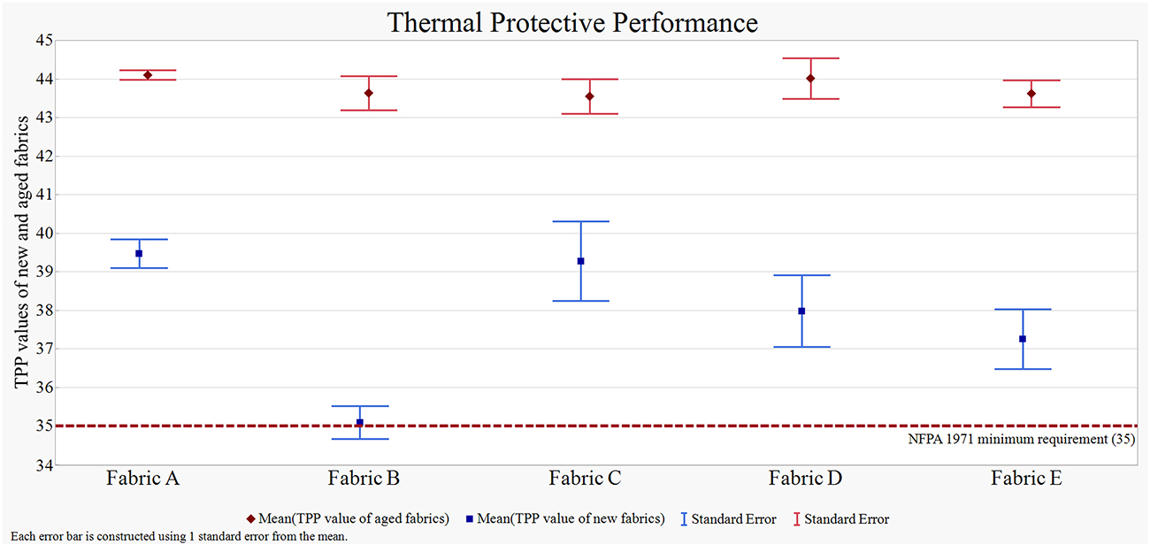
Thermal Protective Performance of the fabrics in both new and aged conditions; blue markers represent the mean TPP values of all the fabrics in new condition, and red markers represent the mean TPP values of all the fabrics in aged condition; the blue line represents the mean TPP value of the new fabrics; the red line represents the mean TPP value of the aged fabrics; the error bars represent one standard deviation from the mean. The figure illustrates that all the aged fabrics exhibited some degree of improvement in TPP after undergoing the aging process.
Trapezoid tearing strength test
The warp tearing strength of the outer shell fabrics in new conditions with different finishes was approximately 200 N (Figure 8). Fabrics with different DWR finishes had slightly higher tearing strength compared to the unfinished fabrics. Therefore, different finishes had a minimal positive impact on the tearing strength of the fabrics. After the aging process, the tearing strength of the fabrics decreased substantially. The average warp-wise tearing strength of all the aged samples was 60.37 N, which was approximately 72% less than 215.14 N, which was the average tearing strength of new fabrics. For passing the tearing strength test, the NFPA 1971 (2020) subsection 7.1.11 has stated that tearing strength will have to be more than 100 N. This indicates that aging severely degrades the tearing strength of all the outer shell fabrics. Statistical differences were seen between the new and aged fabrics. Other research has demonstrated that aramid polymers exhibit sensitivity to UV light, resulting in a significant reduction in their tensile strength.22,57–59 In addition, the DWR treatment did not affect the tensile strength of the fabrics, which also confirms the results of the study done by Wakatsuki et al., (2022).60 Details of the trapezoid tearing strength experimental data and statistical analysis are given in Table S5 and Figure S2.
Figure 8.

Tearing strength of the samples in new and aged conditions; blue markers represent the mean tearing strength values of all the fabrics in new condition, and red markers represent the mean tearing strength values of all the fabrics in aged condition; the blue line represents the trapezoid tearing strength of the new fabrics; the red line represents the mean trapezoid tearing strength of the aged fabrics; the error bars represent one standard deviation from the mean. The tearing strength of all fabrics experienced a significant decrease following the aging process.
Surface analysis
Digital microscopy images of the samples were taken in both new and aged conditions to understand the effect of aging on the fabric surface using the Keyence VHX7000 digital microscope. The images are given in Figure 9. All the aged samples showed some level of yarn breakage on the surface, which suggests that fiber along with DWR finishes are coming off during the aging process.54 The decrease in water and oil repellency, as well as the reduction in contact angle value, can be supported by this phenomenon.
Figure 9.

Optical microscopy images of all fabrics in new and aged conditions. Fabrics a1 and a2 represent the surface images of unfinished fabrics in new and aged conditions respectively; Fabrics b1, c1, and b2, c2 represent the surface images of PFAS-based DWR finished fabrics in new and aged conditions; Fabric d1 and d2 represent the surface images of silicone-based DWR finished fabrics in new and aged conditions; Fabric e1 and e2 represent the surface images of hydrocarbon-based DWR finished fabrics in new and aged conditions. All the aged samples showed some level of yarn breakage on the surface.
In addition to the digital surface imaging, ToF-SIMS and XPS analysis were done to understand the surface chemistry of these fabrics in new as well as aged conditions (Figure 10). ToF-SIMS high lateral resolution mass spectral images acquired in this study, a Burst Alignment setting of 25 keV Bi3 + ion beam was used to raster a 500 μm by 500 μm area. The 2D mapping of the most abundant positive ions is shown in Figure 10. All other positive and negative ions that are potentially coming from the applied finishes and the fiber are given in Figure S3. The fluoromethyl (CF3+) ion was most abundant in Fabrics B and C (PFAS-based DWR finish) (Figure 10- B1, B3, C1, C3), this could be the outermost carbon with three fluorine of the side chain fluorinated polymer (Figure 1). For Fabrics B and C, the aged samples showed a significantly lower number of CF3+ ion detection compared to the new fabrics (Figure 10- B3, C3). The commonly detected positive ions for Fabrics D and E (silicone and hydrocarbon-treated) were SiC6H15O2+ and C2H4CH3+ (Figure 10- D1, E1). A similar trend of lowered number of detections was seen for both fabrics in aged condition (Figure 10- D3, E3). Therefore, it is evident that the aging process is removing a significant amount of finish chemistry from the fabric surface. The most detected positive ion for the unfinished fabric was Na+ (Figure 10- A1). No ions that could potentially come from the finishes applied (i.e., CF3+, SiC6H15O2+, and C2H4CH3+) were detected from the unfinished fabric. Na+ is likely the residual used to neutralize the acid used in para-aramid fiber production.61 Since all the samples were made out of the same meta-aramid and para-aramid fiber blend, negative ions CN− and CNO− were detected in all the samples, indicating that these ions are potentially coming from the amide group (-CONH-) of the aramid polymer.13 ToF-SIMS mostly gives information on the top few nanometers, finishing on the fibers results in blocking the fibers from producing secondary ions. Due to the presence of DWR finishes on the surfaces, the ion beam of ToF-SIMS was not reaching the fiber to give a significant amount of CN− and CNO− ions. However, the detection of these two negative ions increased after the aging process, which again supports the fact that the aging process removed finishes from the surface of the fabrics significantly, therefore, the ion beam was able to ablate more of the fiber in aged fabrics compared to the new fabrics.
Figure 10.
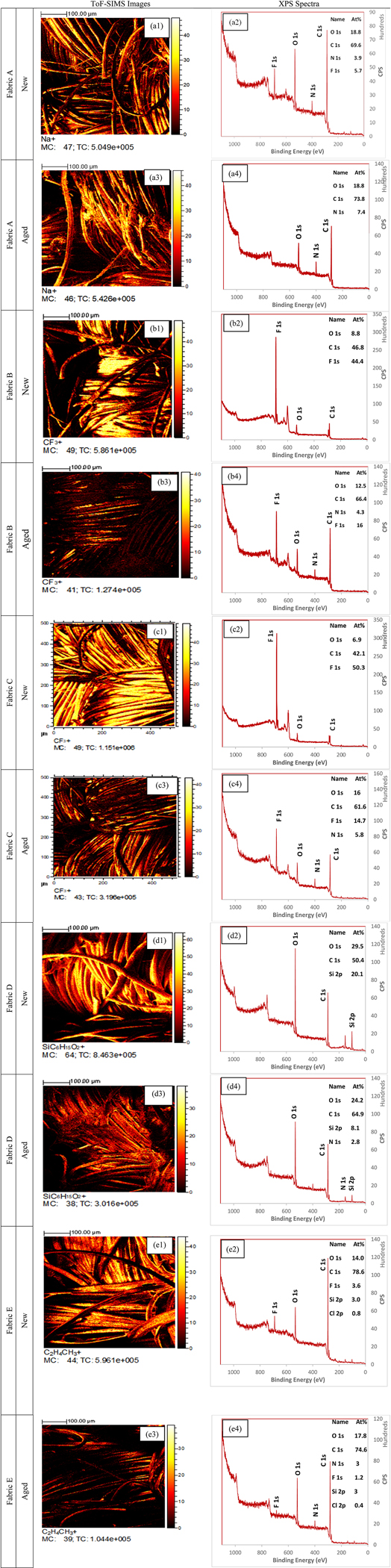
ToF-SIMS images and XPS survey spectra of all the fabrics. Figures a1, a2 and a3, a4 represent the ToF-SIMS image and XPS survey spectra of the unfinished fabric in new and aged conditions; Figures b1, b2, c1, c2 and b3, b4, c3, c4 represent the ToF-SIMS image and XPS survey spectra of the PFAS-based DWR finished fabrics in new and aged conditions; Figures d1, d2 and d3, d4 represent the ToF-SIMS image and XPS survey spectra of the silicone-based DWR finished fabrics in new and aged conditions; Figures e1, e2 and e3, e4 represent the ToF-SIMS image and XPS survey spectra of the hydrocarbon-based DWR finished fabrics in new and aged conditions. Ions (ToF-SIMS) and atomic percentages (XPS) from both PFAS and non-PFAS chemistries were severely reduced after the aging process.
In addition to the semi-quantitative ToF-SIMS analysis, a fully quantitative XPS analysis was also done. Carbon (C), nitrogen (N), oxygen (O), fluorine (F), and silicon (Si), atoms were quantified by the XPS analysis (Figure 10). The trace amount of fluorine in Fabric A (Figure 10- A2) suggests that the fabric is contaminated with fluorine either during the manufacturing process or could come from storage in the laboratory. However, no fluorine was detected after the aging of Fabric A (Figure 10- A4). Fluorine detection from Fabrics B and C in new conditions were 44 and 50 atomic percentages (At%), respectively (Figure 10- B2, C2), which eventually reduced to 16 and 14.7 At%, respectively, after aging (Figure 10- B4, C4). This result again suggests that a significant amount of the finishes are removed during the aging process. For Fabric D (silicone-based DWR finish) the At% of Si was 20 in the new condition, which eventually decreased to eight At% after the aging process (Figure 10- D2, D4). The results indicate a significant amount of loss during the aging process. Fabric E was based on a hydrocarbon (wax) finish. Since XPS cannot detect H, there was no specific information that could be interpreted from the XPS data about the finish of Fabric E (Figure 10- E2 and E4). However, based on the ToF-SIMS data and imaging, it can be concluded that a significant amount of repellent finish was also removed from Fabric E during the aging process. Therefore, it is evident from all the surface analysis techniques that both the PFAS and non-PFAS-based chemistries are subject to break and washed off during the aging process.
Conclusion
This study compared the performance of fabrics with PFAS-based DWR chemistry to fabrics with non-PFAS DWR chemistry, as well as an unfinished fabric control, to investigate any potential trade-offs between applied finish for selected firefighting protective garment materials. The aim was to assess the fabrics’ performance in both new and aged conditions and to inform firefighters who are transitioning to non-PFAS gear about some of the potential performance differences.
The contact angle and repellency results showed that while all DWR-finished fabrics were good at repelling water in both new and aged conditions, fabrics with non-PFAS chemistries were not able to repel diesel fuel efficiently and were relatively flammable after exposure to diesel fuel. However, washing the fabrics removed the absorbed diesel and made them non-flammable. Firefighters using non-PFAS gear should be cautious if they are exposed to flammable liquids at certain fire scenes (i.e., car accidents, auto body shop fires) where the liquids may absorb onto the outer shell and avoid going back to the fire scene without washing or changing their gear.
The thermal protective performance and trapezoid tearing strength showed no notable differences between the PFAS and non-PFAS fabrics. However, both sets of fabrics exhibited a notable reduction in trapezoidal tearing strength after undergoing the aging process. For the firefighting turnout gear materials selected in this study, the addition of PFAS and non-PFAS finishes did not appear to affect the TPP performance and trapezoidal tearing strength.
Digital microscopy images showed that fibers from both sets of fabrics broke and came off during washing and other processes. ToF-SIMS and XPS analysis indicated that ions and atomic percentages from both PFAS and non-PFAS chemistries were severely reduced after the aging process. The data suggest that significant amounts of the DWR finishes were removed during the aging process.
This study focused on a single type of outer shell fabric material with different DWR finishes. Future studies are needed to include other commercially available outer shell fabrics to assess the full extent of the impact of DWR finish on the performance of the outer shell materials in turnout gear. Further investigations are required to determine the impact of contaminated gear from fire burns on the repellency and other performance aspects of the outer shell materials. Additionally, it is essential to conduct further research to determine the level of oil repellency that firefighters actually need in the field to ensure that the performance requirements for the gear do not require the use of PFAS chemistries when they are not actually necessary.
Supplementary Material
Acknowledgments
The authors would like to thank Christina M. Baxter, PhD, Emergency Response TIPS, LLC, for providing valuable feedback on the draft of this paper. The authors acknowledge Dr Chuanzhen Zhou and Dr Sameera Pathirange on conducting ToF-SIMS and XPS analysis respectively at the Analytical Instrumentation Facility (AIF) at North Carolina State University, which is supported by the State of North Carolina and the National Science Foundation (award number ECCS-2025064). The AIF is a member of the North Carolina Research Triangle Nanotechnology Network (RTNN), a site in the National Nanotechnology Coordinated Infrastructure (NNCI).
Funding
The author(s) disclosed receipt of the following financial support for the research, authorship, and/or publication of this article: The funding of the project has been provided by the Fire Prevention and Safety Grants (EMW-2020-FP-01120), part of the Federal Emergency Management Agency’s Assistance to Firefighters Grant Program.
Footnotes
Declaration of conflicting interests
The author(s) declared no potential conflicts of interest with respect to the research, authorship, and/or publication of this article.
Supplemental material
Supplemental material for this article is available online.
References
- 1.Coca A, Williams WJ, Roberge RJ, et al. Effects of fire fighter protective ensembles on mobility and performance. Appl Ergon 2010; 41: 636–641. [DOI] [PubMed] [Google Scholar]
- 2.Mandal S, Mazumder N-U-S, Agnew RJ, et al. Characterization and modeling of thermal protective and thermo-physiological comfort performance of polymeric textile materials—a review. Materials 2021; 14: 2397. [DOI] [PMC free article] [PubMed] [Google Scholar]
- 3.Campbell R and Hall S. United States firefighter injuries in 2021. Quincy, MA: National Fire Protection Association. Research, Data and Analytics Division, 2022. [Google Scholar]
- 4.Park H, Park J, Lin S-H, et al. Assessment of Firefighters’ needs for personal protective equipment. Fashion and Textiles 2014; 1: 8. DOI: 10.1186/s40691-014-0008-3. [DOI] [Google Scholar]
- 5.Kim KS. Health hazards in firefighters. Hanyang Medical Reviews 2010; 30: 296–304. [Google Scholar]
- 6.Demers PA, DeMarini DM, Fent KW, et al. Carcinogenicity of occupational exposure as a firefighter. Lancet Oncol 2022; 23: 985–986. [DOI] [PubMed] [Google Scholar]
- 7.Mazumder NUS and Islam MT. Flame retardant finish for textile fibers. In: Innovative and Emerging Technologies for Textile Dyeing and Finishing. Hoboken, NJ: John Wiley & Sons, 2021, pp. 373–405. [Google Scholar]
- 8.Fent KW, Eisenberg J, Snawder J, et al. Systemic exposure to PAHs and benzene in firefighters suppressing controlled structure fires. Ann Occup Hyg 2014; 58: 830–845. [DOI] [PMC free article] [PubMed] [Google Scholar]
- 9.Mazumder N-U-S, Hossain MT, Jahura FT, et al. Firefighters’ exposure to per-and polyfluoroalkyl substances (PFAS) as an occupational hazard: a review. Frontiers in Materials 2023; 10: 1143411. DOI: 10.3389/fmats.2023.1143411. [DOI] [PMC free article] [PubMed] [Google Scholar]
- 10.Hossain MT, Girase AG and Ormond RB. Evaluating the performance of surfactant and charcoal-based cleaning products to effectively remove PAHs from firefighter gear. Front Mater 2023; 10: 207. [DOI] [PMC free article] [PubMed] [Google Scholar]
- 11.Mokoana VN, Asante JK and Okonkwo OJ. A review on volatilization of flame retarding compounds from polymeric textile materials used in firefighter protective garment. J Fire Sci 2023; 41: 107–121. [Google Scholar]
- 12.Rathour R, Das A and Alagirusamy R. Studies on the influence of process parameters on the protection performance of the outer layer of fire-protective clothing. J Ind Textil 2022; 51: 8107S–8126S. [Google Scholar]
- 13.Islam MT, Rahman MM and Mazumder NUS. Polymers for textile production. In: Frontiers of Textile Materials: Polymers, Nanomaterials, Enzymes, and Advanced Modification Techniques. Hoboken, NJ: John Wiley & Sons, 2020, pp. 13–59. [Google Scholar]
- 14.Mandal S, Mazumder N-U-S, Agnew RJ, et al. Using artificial neural Network modeling to analyze the thermal protective and thermo-physiological comfort performance of textile fabrics used in oilfield workers’ clothing. Int J Environ Res Publ Health 2021; 18: 6991. [DOI] [PMC free article] [PubMed] [Google Scholar]
- 15.Kissa E Fluorinated surfactants and repellents. Boca Raton, Florida: CRC Press, 2001. [Google Scholar]
- 16.Holmquist H, Schellenberger S, van Der Veen I, et al. Properties, performance and associated hazards of state-of-the-art durable water repellent (DWR) chemistry for textile finishing. Environ Int 2016; 91: 251–264. [DOI] [PubMed] [Google Scholar]
- 17.Peaslee GF, Wilkinson JT, McGuinness SR, et al. Another pathway for firefighter exposure to per-and polyfluoroalkyl substances: firefighter textiles. Environ Sci Technol Lett 2020; 7: 594–599. [Google Scholar]
- 18.Hill PJ, Taylor M, Goswami P, et al. Substitution of PFAS chemistry in outdoor apparel and the impact on repellency performance. Chemosphere 2017; 181: 500–507. [DOI] [PubMed] [Google Scholar]
- 19.Keighley J Breathable fabrics and comfort in clothing. J Coat Fabr 1985; 15: 89–104. [Google Scholar]
- 20.Lomax GR. Breathable polyurethane membranes for textile and related industries. J Mater Chem 2007; 17: 2775–2784. [Google Scholar]
- 21.Aidani R, Dolez P and Vu-Khanh T. Effect of thermal aging on the mechanical and barrier properties of an e-PTFE/NomexVR moisture membrane used in firefighters’ protective suits. J Appl Polym Sci 2011; 121: 3101–3110. DOI: 10.1002/app.33991. [DOI] [Google Scholar]
- 22.Hoque MS and Dolez PI. Aging of high-performance fibers used in firefighters’ protective clothing: state of the knowledge and path forward. J Appl Polym Sci 2023; 140: e54255. [Google Scholar]
- 23.Shaid A, Wang L and Padhye R. Textiles for firefighting protective clothing. Firefighters’ clothing and equipment: performance, protection, and comfort. Boca Raton, Florida: CRC Press, 2018, pp. 1–30. [Google Scholar]
- 24.Buck RC, Murphy PM and Pabon M. Chemistry, properties, and uses of commercial fluorinated surfactants. In: Polyfluorinated chemicals and transformation products. Berlin, Heidelberg: Springer, 2012, pp. 1–24. [Google Scholar]
- 25.Mahltig B 13 - hydrophobic and oleophobic finishes for textiles. In: Paul R (ed) Functional Finishes for Textiles. Sawston, UK: Woodhead Publishing, 2015, pp. 387–428. [Google Scholar]
- 26.Derek H Textile finishing. Bradford, Eng: Society of Dyers and Colourists, 2003. [Google Scholar]
- 27.Cousins IT, Vestergren R, Wang Z, et al. The precautionary principle and chemicals management: the example of perfluoroalkyl acids in groundwater. Environ Int 2016; 94: 331–340. DOI: 10.1016/j.envint.2016.04.044. [DOI] [PubMed] [Google Scholar]
- 28.Wang Z, DeWitt JC, Higgins CP, et al. A never-ending story of per-and polyfluoroalkyl substances (PFASs)? Environmental Science & Technology 2017;51(5):2508–2518. [DOI] [PubMed] [Google Scholar]
- 29.Goldenman G, Fernandes M, Holland M, et al. The cost of inaction: a socioeconomic analysis of environmental and health impacts linked to exposure to PFAS. Copenhagen, Denmark: Nordic Council of Ministers, 2019. [Google Scholar]
- 30.Nadal M and Domingo JL. Indoor dust levels of perfluoroalkyl substances (PFASs) and the role of ingestion as an exposure pathway: a review. Curr Org Chem 2014; 18: 2200–2208. [Google Scholar]
- 31.Sjogren P, Montse R, Lampa E, et al. Circulating levels of perfluoroalkyl substances are associated with dietary patterns – a cross sectional study in elderly Swedish men and women. Environ Res 2016; 150: 59–65. DOI: 10.1016/j.envres.2016.05.016. [DOI] [PubMed] [Google Scholar]
- 32.Mastrantonio M, Bai E, Uccelli R, et al. Drinking water contamination from perfluoroalkyl substances (PFAS): an ecological mortality study in the Veneto Region, Italy. Eur J Publ Health 2018; 28: 180–185. DOI: 10.1093/eurpub/ckx066. [DOI] [PubMed] [Google Scholar]
- 33.Domingo JLand Nadal M Human exposure to per-and polyfluoroalkyl substances (PFAS) through drinking water: a review of the recent scientific literature. Environ Res 2019; 177: 108648. [DOI] [PubMed] [Google Scholar]
- 34.Muensterman DJ, Titaley IA, Peaslee GF, et al. Disposition of fluorine on new firefighter turnout gear. Environmental science & technology 2021; 56(2): 974–983. [DOI] [PubMed] [Google Scholar]
- 35.van der Veen I, Schellenberger S, Hanning A-C, et al. Fate of per-and polyfluoroalkyl substances from durable water-repellent clothing during Use. Environmental science & technology 2022; 56(9): 5886–5897. [DOI] [PMC free article] [PubMed] [Google Scholar]
- 36.Barzen-Hanson KA, Roberts SC, Choyke S, et al. Discovery of 40 classes of per-and polyfluoroalkyl substances in historical aqueous film-forming foams (AFFFs) and AFFF-impacted groundwater. Environmental science & technology 2017; 51: 2047–2057. [DOI] [PubMed] [Google Scholar]
- 37.Vaughn B, Andrea W and Kyle S. Perfluorooctanoic acid (PFOA) exposures and incident cancers among adults living near a chemical plant. Environmental health perspectives 2013; 121: 1313–1318. DOI: 10.1289/ehp.1306615. [DOI] [PMC free article] [PubMed] [Google Scholar]
- 38.Chang ET, Adami H-O, Boffetta P, et al. A critical review of perfluorooctanoate and perfluorooctanesulfonate exposure and cancer risk in humans. Null 2014; 44: 1–81. DOI: 10.3109/10408444.2014.905767. [DOI] [PubMed] [Google Scholar]
- 39.Daniels RD, Kubale TL, Yiin JH, et al. Mortality and cancer incidence in a pooled cohort of US firefighters from San Francisco, Chicago and Philadelphia (1950–2009). Occup Environ Med 2014; 71: 388–397. [DOI] [PMC free article] [PubMed] [Google Scholar]
- 40.LeMasters GK, Genaidy AM, Succop P, et al. Cancer risk among firefighters: a review and meta-analysis of 32 studies. Journal of occupational and environmental medicine 2006;48: 1189–1202. [DOI] [PubMed] [Google Scholar]
- 41.Soteriades ES, Kim J, Christophi CA, et al. Cancer incidence and mortality in firefighters: a state-of-the-art review and meta-analysis. Asian Pac J Cancer Prev APJCP 2019; 20: 3221. [DOI] [PMC free article] [PubMed] [Google Scholar]
- 42.Laroche E and L’Espérance S. Cancer incidence and mortality among firefighters: an overview of epidemiologic systematic reviews. Int J Environ Res Publ Health 2021; 18: 2519. [DOI] [PMC free article] [PubMed] [Google Scholar]
- 43.van der Veen I, Hanning A-C, Stare A, et al. The effect of weathering on per- and polyfluoroalkyl substances (PFASs) from durable water repellent (DWR) clothing. Chemosphere 2020; 249: 126100, DOI: 10.1016/j.chemosphere.2020.126100. [DOI] [PubMed] [Google Scholar]
- 44.Schellenberger S, Gillgard P, Stare A, et al. Facing the rain after the phase out: performance evaluation of alternative fluorinated and non-fluorinated durable water repellents for outdoor fabrics. Chemosphere 2018; 193: 675–684. [DOI] [PubMed] [Google Scholar]
- 45.Schellenberger S, Jonsson C, Mellin P, et al. Release of side-chain fluorinated polymer-containing microplastic fibers from functional textiles during washing and first estimates of perfluoroalkyl acid emissions. Environmental Science & Technology 2019; 53: 14329–14338. [DOI] [PubMed] [Google Scholar]
- 46.Maizel A, Thompson A, Tighe M, et al. Per-and polyfluoroalkyl substances in new firefighter turnout gear textiles. Gaithersburg, MA: NIST, 2023. [Google Scholar]
- 47.Mazumder N-U-S. Characterizing the tensile strength of outer layer fabrics used in firefighters’ protective clothing under radiant heat exposure. Stillwater, OK: Oklahoma State University, 2021. [Google Scholar]
- 48.Mazumder N-U-S, Mandal S, Agnew RJ, et al. Characterizing the tensile strength of the fabrics used in firefighters’ bunker gear under radiant heat exposure. Polymers 2022; 14: 296. [DOI] [PMC free article] [PubMed] [Google Scholar]
- 49.Rezazadeh M, Bespflug CJ, Torvi DA, et al. Predicting mechanical strength of in-use firefighter protective clothing using near-infrared spectroscopy. Fire Technol 2018; 54: 1759–1781. [Google Scholar]
- 50.Hoque MS, Saha A, Chung HJ, et al. Hydrothermal aging of fire-protective fabrics. J Appl Polym Sci 2022; 139: e52666. [Google Scholar]
- 51.Rezazadeh M and Torvi DA. Assessment of factors affecting the continuing performance of firefighters’ protective clothing: a literature review. Fire Technol 2011; 47: 565–599. [Google Scholar]
- 52.Day M, Cooney J and Suprunchuk T. Durability of firefighters’ protective clothing to heat and light. Textil Res J 1988; 58: 141–147. [Google Scholar]
- 53.Corbally MA, Williams MR, Chappell JN, et al. Detecting chemical vapor diffusion through firefighter turnout gear. Int J Environ Res Publ Health 2021; 18: 4833. [DOI] [PMC free article] [PubMed] [Google Scholar]
- 54.Schellenberger S, Liagkouridis I, Awad R, et al. An outdoor aging study to investigate the release of per-and polyfluoroalkyl substances (PFAS) from functional textiles. Environmental Science & Technology 2022; 56: 3471–3479. [DOI] [PMC free article] [PubMed] [Google Scholar]
- 55.Vogelpohl TL. Post-use evaluation of fire fighter’s turnout coats. Lexington, KY: University of Kentucky, 1996. [Google Scholar]
- 56.Loftin DH. The durability of flame resistant fabrics in an industrial laundry environment. In: Performance of protective clothing: fourth volume. West Conshohocken, PA: ASTM International, 1992. [Google Scholar]
- 57.Zhang H, Zhang J, Chen J, et al. Effects of solar UV irradiation on the tensile properties and structure of PPTA fiber. Polym Degrad Stabil 2006; 91: 2761–2767. [Google Scholar]
- 58.Zhu X, Yuan L, Liang G, et al. Unique UV-resistant and surface active aramid fibers with simultaneously enhanced mechanical and thermal properties by chemically coating Ce 0.8 Ca 0.2 O 1.8 having low photocatalytic activity. J Mater Chem A 2014; 2: 11286–11298. [Google Scholar]
- 59.Fulton M Evaluating the performance of thermally and UV aged firefighters’ protective clothing using both destructive and non-destructive methods. Saskatoon, Canada: University of Saskatchewan, 2017. [Google Scholar]
- 60.Wakatsuki K, Matsubara M, Watanabe N, et al. Effects of m-Aramid/p-Aramid blend ratio on tensile strength due to UV degradation for firefighter clothing fabrics and development of predictive equation for tensile strength. Polymers 2022; 14: 3241. [DOI] [PMC free article] [PubMed] [Google Scholar]
- 61.Brauckmann JO, Verhoef R, Schotman AH, et al. Solid-state nuclear magnetic resonance characterization of residual 23Na in aramid fibers. J Phys Chem C 2019; 123: 14439–14448. [Google Scholar]
Associated Data
This section collects any data citations, data availability statements, or supplementary materials included in this article.