

Abstract
Subretinal injection is an effective method for direct delivery of therapeutic agents to treat prevalent subretinal diseases. Among the challenges for surgeons are physiological hand tremor, difficulty resolving single-micron scale depth perception, and lack of tactile feedback. The recent introduction of intraoperative Optical Coherence Tomography (iOCT) enables precise depth information during subretinal surgery. However, even when relying on iOCT, achieving the required micron-scale precision remains a significant surgical challenge. This work presents a robot-assisted workflow for high-precision autonomous needle navigation for subretinal injection. The workflow includes online registration between robot and iOCT coordinates; tool-tip localization in iOCT coordinates using a Convolutional Neural Network (CNN); and tool-tip planning and tracking system using real-time Model Predictive Control (MPC). The proposed workflow is validated using a silicone eye phantom and ex vivo porcine eyes. The experimental results demonstrate that the mean error to reach the user-defined target and the mean procedure duration are within an acceptable precision range. The proposed workflow achieves a 100% success rate for subretinal injection, while maintaining scleral forces at the scleral insertion point below 15mN throughout the navigation procedures.
Keywords: Surgical Robotics: Planning, Computer Vision for Medical Robotics, Medical Robots and Systems
I. INTRODUCTION
RETINAL diseases such as Age-related Macular Degeneration (AMD), diabetic retinopathy, inherited retinal dystrophies, and myopia affect millions of people worldwide and are among the leading causes of retinal blindness. According to a report from the World Health Organization, a minimum of 2.2 billion people are affected by vision impairment at the global level. Of these, at least 1 billion cases are considered preventable or treatable [1]. One way to treat inherited retinal dystrophies is with subretinal injection of gene therapy vectors. Compared to the intravitreal space, the subretinal space is anatomically closed and immune privileged. Smaller amounts of potentially toxic drugs are sufficient using the subretinal approach [2]. Current cell therapies for macular degeneration use the subretinal approach [3]. Choroidal neovascularization with subretinal hemorrhage secondary to wet AMD or pathological myopia is sometimes treated by injecting tissue plasminogen activator into the subretinal space to dissolve the thrombus for displacement or removal. Anti-vascular endothelial growth factor drugs are also injected to prevent abnormal blood vessels from further hemorrhage. There are three predominant delivery routes to deliver therapeutics to the photoreceptors and Retinal Pigment Epithelium (RPE): intravitreal injection, subretinal injection, and suprachoroidal injection [4]. Intravitreal injection directly injects the drug into the vitreous humor. Despite its simplicity, this method may deliver a very limited amount of the drug to the intended subretinal space. Suprachoroidal injection has similar disadvantages. Among the three delivery methods, subretinal injection is the most effective [5]. However, it also presents more difficulties for surgeons.
The challenges to the surgeon include but are not limited to the physiological limitation of human hand tremor, axial visual resolution on the micron scale, the need to puncture the retina and to detach a portion of the retina, and reflux of drug from the injection site. The estimated root mean square amplitude of hand tremor at the surgical tip is reported to be 182μm [6]. By comparison, a healthy eye’s mean central foveal thickness is 182 ± 23μm [7]. The duration of injection for drug delivery typically lasts around 5 minutes [8]; during this time, the surgeon must hold the surgical instrument still. Laboratory studies show that the tremor associated with holding the instrument still are on the order of 100μm and tend to worsen with fatigue [9]. All such motion instability results in lateral movement of the surgical instrument within the subretinal tissue, potentially causing damage to the retina and leading to increased reflux. Introducing robot-assisted subretinal surgery is advantageous to address the aforementioned limitations imposed by human physiology and to ensure the safety and precision of the operation.
Currently, three types of robotic systems are in development for retinal microsurgery, including smart surgical tools, telemanipulation, and comanipulation [10]. A group from Carnegie Mellon University developed a handheld instrument called ”Micron”, which reduced hand tremor by 90% in a point task [11]. The advantages of telemanipulation systems include the possibility of motion scaling and tremor filtering. The team at the University of Oxford accomplished subretinal injections of recombinant tissue plasminogen activator for the first time in three patients by utilizing the Preceyes telemanipulation robotic system [12]. A successful retinal vein cannulation was demonstrated in anesthetized pigs using the same system [13]. Comanipulation systems such as the Steady Hand Eye Robot (SHER) from Johns Hopkins University (JHU) [14] require the surgeon to hold the surgical instrument to operate. The manipulator can remain static and reduces hand tremor through robot arm stiffness and adjustment of the control gain. Gijbels et al. [15] achieved the world’s first-in-human robot-assisted retinal vein cannulation using the KU Leuven robotic comanipulation system.
This work combines the SHER with iOCT (Fig. 1a) to develop a workflow for autonomous needle navigation for subretinal injection. Our main contributions are:
Fig. 1.

Experimental setup of iOCT guided autonomous needle navigation for subretinal injection: (a) left, general view, (a) right, close view of the surgical area, (b) a silicone eye phantom (left), an ex vivo open-sky eye (middle), and an ex vivo intact eye (right).
We propose an autonomous needle navigation procedure for subretinal injection, which is designed to be adaptable for various eye models and different combinations of lenses and magnifications. The robot’s motion is fully automated, as shown in Fig. 2, with users participating only in the initial setup (step 1), specifying the target (step 3), and injecting fluid (step 5).
We present two CNNs to determine the 3D position of the tool-tip inside the iOCT coordinates, eliminating the requirement for segmenting the entire needle [16], [17]. Each of the two networks predicts the tool-tip position within two sequential 2D images: a top-down image generated from the C-scan1 and a B-scan2 taken at the tool-tip position in the top-down image.
We strictly enforce the Remote Center of Motion (RCM) [18] constraint during the entire workflow, which minimizes the scleral force at the incision point. This is validated by measuring the scleral force during the navigation process with intact eyes. We demonstrate that tuning the control gains makes it possible to keep the scleral force exerted on the tool shaft sufficiently below the safe limit. This approach also assists in reducing the tool’s deformation, which may affect its precision in reaching the target.
Fig. 2.

6-step workflow , which includes experimental setup, Jacobian matrix calculation, target definition, needle navigation, subretinal injection, and tool retraction.
The proposed method is tested and confirmed using a silicone eye phantom, open-sky eyes, and intact eyes. Once the desired target position is reached, we inject the Balanced Salt Solution (BSS) until iOCT observes a clear bleb for all ex vivo porcine eye experiments. In order to assess that scleral forces remain within a safe limit, we employ a surgical tool developed by He et al. [19]. This tool integrates Fiber Brag Grating (FBG) sensors to measure the scleral forces applied to the tool shaft.
II. RELATED WORK
Robot-assisted subretinal injection has been subjected to comparison with manual procedures in various eye models and experiments, including artificial retina models [20], ex vivo porcine eyes [21], and in-human trials [8]. Robotic injections outperform manual injections in terms of achieving a higher success rate, reducing the incidence of reflux, minimizing RPE penetrations, and mitigating drift and tremor [20], [21]. Nevertheless, all these efforts were conducted using a master-slave approach, which necessitated the surgeon’s involvement throughout the entire process. In contrast, our proposed workflow only entails user selection of the target point and the injection of BSS into the subretinal space. The SHER, operating through a combination of optimal control and deep learning techniques, autonomously manages all aspects of the navigation process. Deep learning methods are applied to retinal surgery in various fields. Zhou et al. [16] developed a needle segmentation method inside volumetric OCT images using a fully convolutional neural network. Sommersperger et al. [22] segmented both the needle and retinal surface to determine the distance between the needle-tip and various retinal layers. Our previous work [23], [24] showed the feasibility of using a CNN to predict the position of the surgical tool-tip and the distance vector between the current tool-tip position and the target position using a single top-down view. One advantage of predicting the tool-tip position instead of segmenting the entire needle is that it may require less labeling effort.
OCT is a non-invasive imaging technique that can capture 2D or 3D scans of retinal layers with a resolution of micrometers [5]. The difference between OCT and iOCT is that iOCT integrates the OCT system into a surgical microscope, simultaneously providing both a microscope view and OCT scans in real time. Prior work incorporated OCT into their robotic systems to achieve subretinal injection at a defined depth. Kang et al. [25] developed a handheld common-path swept source OCT system to inject at micro-level depth using ex vivo bovine eyes. Wei et al. [26] used a low-cost camera-integrated OCT system with a human in the loop to navigate the surgical tool to a target region for subretinal injection. The introduction of iOCT allows surgeons to visualize the cross-sectional images of the surgical scenes in real time, facilitating the autonomous procedure with the assistance of robotic systems. Chen et al. [27] utilized OCT images intraoperatively to realize an automated cataract extraction procedure. Draelos et al. [28] achieved automated needle insertion in deep anterior lamellar keratoplasty based on the real-time volumetric OCT scans. Dehghani et al. [17] established a two-step process that involved instrument pose estimation, online registration, and trajectory planning to achieve precise subretinal positioning autonomously. In our prior work [29], we calibrated the microscope and OCT to generate real-time tool-axis-aligned B-scans for autonomous subretinal injection. However, these studies primarily focused on experiments that use open-sky eyes [30], which had fewer constraints than intact eyes. Intact eye experiments conducted in this work may have additional limitations, such as RCM constraints and distortion and magnification effects caused by the native or artificial lens.
III. METHOD
A. Experimental Setup
Fig. 1a shows our experimental setup, which contains a SHER (Johns Hopkins University), an iOCT system (Leica Proveo 8), a Binocular Indirect Ophthalmo Microscope (BIOM) lens (OCCULUS BIOM ready), a light source (Alcon Accurus 20G Sapphire Wide Angle Endoilluminator), a XYZ linear stage (Physik Instrumente Q-522 Q-motion), a 3D-printed eye socket, and a customized surgical needle system. The SHER has 5 degrees of freedom, comprising 3 translational and 2 rotational movements [14]. The iOCT system provides the top-down microscope view and the volume scan (i.e., C-scan) of the Region of Interest (ROI), which is set to be 6mm × 6mm × 3.38mm. Setting the ROI precisely within the eyeball is challenging due to factors such as the presence of a BIOM lens, the position of the microscope, and the influence of the cornea and internal lens. Each volume scan includes 200 B-scans, and each B-scan comprises 500 A-scans, consisting of 1024 pixels along the Z-axis. The scanning frequency is 0.25Hz. The OCT scan (C-scan) is employed during step 2, step 3, and the final error calculation. The autonomous needle navigation in step 4 relies on information derived from steps 2 and 3. To align the microscope’s focus with the iOCT system, a BIOM lens is attached to the bottom of the microscope, which is necessary for intact eye experiments. Using a BIOM lens can result in image distortion and changes in magnification, which in turn could alter the size of ROI, Fig. 3. In our experiments, we tried to avoid putting our ROI on the edge of the BIOM lens view. The XYZ linear stage (see Fig. 1a) is utilized to adjust the eye’s position to achieve the image’s best resolution. The eye socket is designed to hold porcine eyes and maintain the curvature of the fundus during open-sky eye experiments. The customized surgical needle system includes a 110-micron needle, two syringes, a tube, and a syringe holder, which is attached to the end-effector of the SHER. The needle will remain static during the subretinal injection process while the fluid is injected using the other syringe that has no contact with the robot.
Fig. 3.

(a) Original top-down view of the ROI without the BIOM lens (see Fig. 1). (b) The top-down view of the silicone eye phantom with the BIOM lens. (c) The top-down view of an open-sky eye with the BIOM lens. (d) Illustration of the B-scan. (e) The top-down view of an intact eye with the BIOM lens. (f) An extreme case of the distortion caused by the BIOM lens when the needle is positioned at the edge of the field of view.
B. Eye Models
In this work, we conduct experiments using three different eye models. The first model (Fig. 1b left) is a customized silicone eye phantom designed specifically for eye-related experiments. It features an orange base (Smooth-On KX Flex60) with an inner diameter of 25.4mm. We use a water-based pen (Uni-ball Signo 0.38mm red) to simulate blood vessels. A protective layer (Smooth-On VytaFlex60) is applied to the inner surface to prevent accidental removal of the drawn blood vessels. The second model is an open-sky eye (Fig. 1b middle), which is derived by removing the superior portion of the porcine eye. Initially, a trocar (Alcon 20G Trocar) is employed to cut a small incision into the scleral wall, followed by the use of a scissor (STORZ Westcott Type Utility Scissors E3322) to remove the anterior portion of the eye just posterior to the limbus. To maintain consistency, we retain most of the vitreous inside the eye to eliminate the impact of different refractive indexes between the air and the retinal tissue. The last model is an intact eye (Fig. 1b right), meaning that no internal components are removed. We test our workflow using 10 different open-sky eyes and 10 different intact eyes to ensure comprehensive evaluation.
C. Deep Learning-based Tool-tip Prediction
To automatically locate the tool-tip position within the iOCT coordinates, we train two CNNs to predict tool-tip positions in two sequential images. The training dataset consists of 400 images for each network. The tool-tip positions are manually labeled using an online labelling tool called SUPERVISELY. The first image (Fig. 4a) is the top-down image (200 × 500 pixels) generated by summing up all the layers of the volume scan along the Z-axis. The second image (Fig. 4b) is the specific B-scan (1024 × 500 pixels) at the tool-tip position of the first image. The two CNNs share the same logic, which includes an encoder and a decoder. Our encoder uses ResNet-18 [31] as a backbone, with modifications such as changes to each layer’s input and output sizes and the removal of the fully connected layer. We decode the last layer of the encoder in the form of a U-net [32]. The input is one of the 2D images, and the output is the tool-tip coordinate sharing the same X-axis position, Fig. 4. By combining these two outputs, we can derive the 3D coordinates of the tool-tip position in the iOCT coordinates. We collected 200 data points using a silicone eye phantom and an additional 200 data points using open-sky eyes. The two CNNs are trained with an initial learning rate of 0.001 and 0.0001 respectively, a batch size of 32 and 16, the Adam optimizer [33], and the cross-entropy loss function [24], using 80% of the 400 images for training and the remaining 20% for validation. To address the distortion and magnification resulting from the BIOM lens, we train our CNN using various types of augmentation techniques, including random rotation, cropping, resizing, dropout, and change of brightness, Fig. 5. During the data collection process, some B-scans are missed due to a connection issue, resulting in black lines such as the image located at Row 2 Column 3 in Fig. 5. The trained results are tested in experiments using different eye models and subsequently evaluated for both pixel and metric accuracy (see Table I in Section IV).
Fig. 4.
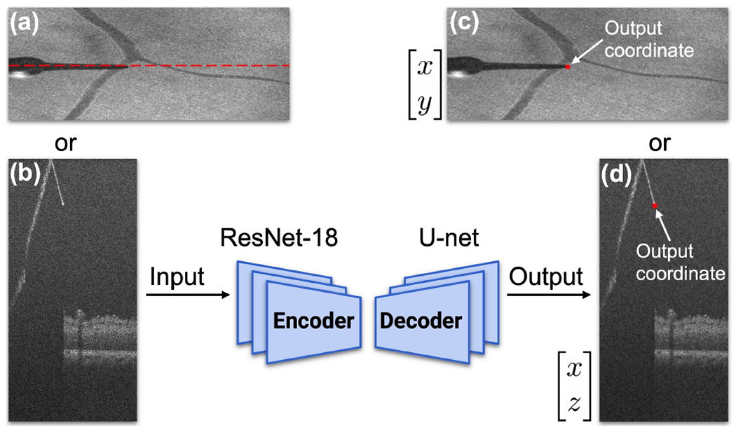
Basic structure of proposed convolutional neural network. (a)-(b) Input of the network. (a) Top-down image of the ROI. (b) B-scan image at the tooltip position, indicated by the red dashed line in (a). (c)-(d) Output coordinates of the network.
Fig. 5.

Examples of data augmentation techniques, which includes dropout, cropping, rotation, resizing, change of brightness, and other artifacts.
TABLE I.
Mean Errors for Reaching the Target
| Eye Models (units) | mean X error | mean Y error | mean Z error |
|---|---|---|---|
| Silicone (pixel) | 2.5±3.90 | 1.05±2.10 | 10.0±13.13 |
| Open-sky (pixel) | 2.4±2.51 | 2.1±3.09 | 7.4±8.46 |
| Intact (pixel) | 4.6±6.02 | 2.4±3.30 | 7.2±12.42 |
| Silicone (μm) | <30.0±46.75 | <31.5±62.98 | <33.0±43.34 |
| Open-sky (μm) | <28.8±30.12 | <63.0±92.78 | <24.4±27.92 |
| Intact (μm) | <55.2±72.26 | <72.0±99.09 | <23.8±40.99 |
D. iOCT to Robot Coordinates Registration
Given the time required for volume scanning using our current setup, the available data points for registration are limited due to the time constarints and efficiency considerations. One simple and effective way to register between iOCT and robot coordinates is to calculate the Jacobian matrix between small changes in two coordinates:
| (1) |
where represents small changes in the robot frame (Fig. 1a in red), is the Jacobian matrix, and denotes small changes in the iOCT frame (Fig. 1a in blue).
This Jacobian matrix can be considered as a local linear approximation of the transformation between two coordinates. This is appropriate for our experimental setup because the transformation might vary along the scanning direction due to the distortion caused by the BIOM lens. According to (1), we need at least 4 distinct points to form 9 different changes along three axes in both sets of coordinates for calculating the Jacobian matrix. Considering 4 points , i = 1,2,3,4 in robot coordinates, and the corresponding 4 points , j = 1,2,3,4 in iOCT coordinates, we can reformulate (1) with multiple measurements as:
| (2) |
After obtaining the local Jacobian matrix, we can transfer any point in iOCT coordinates to robot coordinates through:
| (3) |
E. Differential Dynamic Programming (DDP)-based MPC
After determining the target position in the robot coordinates, the next step is to control the robot to reach the position safely and accurately. In this paper, a DDP-based [34] MPC is proposed to achieve this goal. The time horizon is set to be 5s. The time-step for each trajectory is set to be 0.078125s. The current state of the tool-tip is sent to a Geometric Control Optimization and Planning Library (GCOP) [35] developed at JHU to generate an optimal trajectory toward the target using DDP. Fig. 6a shows how MPC works between Robot Operating System (ROS) nodes. We track each optimal trajectory for a small step, and then generate a new optimal trajectory using the updated state. For each small step, the end state is identical to the initial state of the next small step, ensuring the smoothness of the robot movement. This process is repeated until the Euclidean distance between the tool-tip and the target is less than 20μm. The cost function is subject to several constraints:
| (4) |
| (5) |
| (6) |
| (7) |
Fig. 6.

Overview of the framework: (a) ROS node communications for DDP-based MPC. (b) Illustration of RCM constraint (6). (c) Implementation of RCM constraint during the navigation process.
In (4), , where is the tool-tip position, is the orientation of the tool, is the linear velocity, and is the angular velocity relative to robot base frame. The control , where are translational forces, and are torques in end-effector frame, which can be transferred to robot joint torques through robot internal controller. The RCM constraint (6) is illustrated in Fig. 6b and 6c, which minimizes the length of the red dash line to reduce the scleral force at the scleral incision point. Any forces resulting from the translational movement at this point may cause damage to the eye. Applying additional force to the scleral incision point could also lead to the deformation of the needle, which can affect the accuracy to reach the desired target. The total cost function is formulated as:
| (8) |
where is the initial time, is the finial time, is the final state, and is the desired state. We use logarithm function to define a rotation error vector, i.e. is a diagonal positive semi-definite matrix. The diagonal gains corresponding to are set to be zeros since is regulated in RCM constraint term. is a diagonal positive definite matrix, and is the weight of RCM constraint. The cost function (8) is designed to achieve three objectives: minimize the error in reaching the desired point , minimize the effort in controlling , and penalize deviation from the scleral incision point .
F. Scleral Force Measurement
In previous work [36], we demonstrated that by integrating RCM constraint into the cost function of the optimal control, we could minimize the scleral force within 60mN during navigation. In addition to the primary experiments, we also utilize a surgical tool integrated with nine FBG sensors [19], Fig. 7a, to measure the scleral force during steps 2, 3, 4, and 6 as depicted in Fig. 2. The scleral force is determined by correlating strain at FBG sensors with moments using calibrated coefficient matrices, enabling precise force measurement relative to the sensor distance. The subretinal injection process (step 5) is not included because the syringe in our setup does not fit this surgical tool. Due to the significant difference in diameter between the FBG tool (300μm) and the needle used during training (110μm), the network’s predictions may not be very accurate, Fig. 7b and 7c. It implies transferring a defined target in step 3 to robot frame using the calculated Jacobian may be inaccurate. Given that the primary objective of employing the FBG-integrated tool is to measure scleral forces throughout the entire navigation process, we do not necessarily need to use the Jacobian to find the defined target. Instead, we propose replacing step 3 with a procedure where a random target point within the ROI is selected and directly fed to the robot. The selection of random target points is reserved only for experiments involving scleral force measurement, and we will discuss the experimental details in the following section. The safe limit of the scleral force could be as small as 120mN as reported in [37].
Fig. 7.

(a) The FBG-integrated tool. (b) The top-down image of the tool in an intact eye with lens removed. (c) The corresponding B-scan of the tool. The red points are the predicted tool-tip positions by the network.
IV. EXPERIMENTS AND RESULTS
For our primary experiments, we employed three eye models, including a silicone eye phantom, open-sky eyes, and intact eyes, Fig. 1b, to assess the efficacy of our workflow. For silicone eye phantom experiments, we selected 20 different targets above the retinal surface. We utilized a total of 20 porcine eyes, allocating 10 for open-sky experiments and the remaining 10 for intact eye experiments, with each eye being used in a single trial. To eliminate the effect of different refractive indices between the air and the retinal tissue in open-sky eye experiments, we retained some vitreous humor in the lower half of eye. We did not remove any internal components from the eye for intact eye experiments, i.e., all the vitreous humor and the lens remained. For each ex vivo porcine eye experiment, we selected the target position right above the RPE layer. We set the stop condition for step 2 and step 4 to be when the Euclidean distance between the current tool-tip position and the target was less than 20μm for both steps. Once the user-defined target was reached, we continued injecting the BSS until a clear bleb was visible in the subretinal space through iOCT. We did not regulate the injection speed of the BSS during the experiment, as our primary objective was to evaluate the effectiveness of our workflow in achieving subretinal injection. We recorded the duration of the subretinal injection process from step 2 to step 6, which represents a typical timeframe for this procedure. To measure the scleral forces between the tool shaft and the sclera, we randomly selected 10 positions within ROI as targets in step 3 using two intact eyes. The FBG tool was rebalanced at the beginning of each new trial to remove the noise caused by the previous trial.
All the ROS nodes were executed on a desktop computer equipped with an RTX 3090 GPU. The process of selecting the target was done using ImFusion (München, Germany), a medical image processing software. The CNN inference was performed at a frequency of approximately 40Hz, while the DDP-based optimal trajectory was generated at a frequency of around 15Hz. The inference time was negligible since the iOCT volume scan rate is merely 0.25Hz. The FBG reading was recorded at a rate of 200Hz. The mean training errors for top-down images along XY-axis were 2.58, and 2.06 pixels respectively. The mean validation errors for top-down images along XY-axis were 0.60, and 0.30 pixels respectively. The mean training errors for B-scan images along XZ axes were 1.59, and 3.67 pixels respectively. The mean validation errors for B-scan images along XZ axes were 0.55, and 1.39 pixels respectively.
The mean errors to reach the user-defined target positions along XYZ axes were presented in Table I. To calculate the distance error for each trial, we manually label the landing position of the tool-tip inside Imfusion after the robot stops and compare the landing position with the previously defined target position.This error is represented in pixel units. As quantifying the pixel error may be challenging (given potential changes in magnification), we converted pixels errors to metric errors based on the original size of the ROI, i.e., 6 × 6 × 3.38mm for 500 × 200 × 1024 pixels. In this case, the size of each pixel along XYZ axes corresponded to 12μm, 30μm, and 3.3μm respectively. Fig. 8 was the corresponding box plot, and Fig. 9 illustrated the distributions of errors along three axes. Table II showed mean time duration for three eye models at each step of the workflow, as well as the whole-time duration from step 2 to step 6. Fig. 10 displayed six out of twenty B-scans obtained after successfully injecting a certain amount of BSS into the subretinal space. Fig. 11a was the scleral force measured for 10 different trials. Among these trials, 8 involved selecting target above the RPE layer, while the remaining 2 trials focused on targets positioned below the RPE layer. Fig. 11b represented the case where the target was defined in the subretinal space, while Fig. 11c showed the case where the target was selected about 100μm below the RPE layer. This was intentional because the increments in measured scleral force for targets above the RPE layer were not significant to be observed. The brown line in Fig. 11a represented another trial in which the target was positioned below the RPE layer. To create a smoother line plot, we plotted only one point for every 50 points, corresponding to the maximum value within the range.
Fig. 8.

Box plot analysis of errors for reaching the target in different eye models along XYZ axes.
Fig. 9.

Distributions of errors for different eye models along XYZ axes.
TABLE II.
Mean Time Duration
| Eye Models | Silicone | Open-sky | Intact |
|---|---|---|---|
| # of trials | 20 | 10 | 10 |
| Step 2 | 68.37s | 71.53s | 66.08s |
| Step 3 | 47.16s | 74.15s | 66.27s |
| Step 4 | 24.22s | 29.94s | 24.69s |
| Step 5 | N/A | 50.94s | 32.90s |
| Step 6 | 7.70s | 8.50s | 8.71s |
| Total | 2m 27.45s | 3m 55.06s | 3m 18.65s |
Fig. 10.

Six examples of successful subretinal injections. The first row is derived from open-sky eye experiments, while the second row is derived from intact eye experiments. Clear blebs are formed in all examples.
Fig. 11.

Experimental results of scleral force measurement: (a) The norm of scleral fore measured in step 2, 3, 4, and 6 for 10 trials. (b) The trial that defines the target right above the RPE layer. (c) The trial that defines the target around 100μm below the RPE layer.
V. DISCUSSION
In this work, we introduce an autonomous needle navigation procedure for subretinal injection, which are tested using various eye models, including intact eyes. When compared to open-sky eye experiments [17], [25], [26], [30], the intact eye experiments present more challenges, such as compliance with RCM constraints and the effects of native lens. Our experimental results show the robustness of our workflow in addressing these challenges through online registration between robot and iOCT coordinates, as well as CNN-based predictions.
Nevertheless, certain results still require further clarification. The relatively large training errors for the two CNNs are due to the aggressive data augmentation techniques used during training. This is necessary for our experimental setup as the trained network parameters are used for all three eye models. Although we have the largest training error for the Z-axis in pixel units, it is important to consider that each pixel represents a smaller distance along the Z-axis compared to the X and Y axes. In terms of metric units, the Z-axis error is the smallest. The actual mean errors in Table I and Fig. 8 should be smaller than ones we show due to the utilization of the BIOM lens. The BIOM lens magnifies the ROI, which means the actual scanning size is smaller than 6 × 6 × 3.38mm. This effect is in greatest in intact eye experiments because each eye contains an additional lens that amplifies the ROI. It is not possible to determine the precise scanning size since the position or height of the BIOM lens will vary for each eye. However, we have measured that the diameter of the tool-tip in Fig. 3e is approximately four times larger than the diameter of the tooltip in Fig. 3a. This suggests that the ROI along the XY axes should be around 1.5 × 1.5mm instead of 6 × 6mm.
The mean total operation time for the three eye models, from step 2 to step 6, is less than 4 minutes. Steps 2 and 3 pose the most significant time demands primarily because of the time needed for volume acquisition. Step 2 necessitates four volume scans, while step 3 involves a single volume scan. Furthermore, the manual selection and input of the target position into the iOCT coordinates extend the time required for step 3 compared to other steps. An improvement to this process could be achieved by enabling the selection of the target position within the iOCT coordinates through a simple mouse click, followed by automatic publication of this position to the robot. We do not include the precise duration of the experimental setup, which is less than 30 minutes. The total duration of the surgery is within an acceptable range, noting that the mean surgical time of robot-assisted subretinal injection surgery is reported to be 42.7 minutes in [8]. The iOCT that we use is a spectral-domain OCT, which has a lower scanning speed as compared to a swept-source OCT (SS OCT). In future work, we could improve our efficiency by upgrading our iOCT to an SS OCT. Another way is to increase the control gain of our tracking algorithm, which is set to be relatively small in our experiments in order to achieve optimal performance with respect to the RCM constraint.
This work demonstrates the feasibility of our workflow for subretinal injection by successfully injecting BSS into the subretinal space for all 20 ex vivo porcine eye experiments. However, further work is necessary to analyze and address the breaks that occur in the retinal layers caused by the injection, as these breaks are the primary cause of injectate reflux and complications arising from the surgery. Fig. 11 demonstrates that all scleral forces generated during the navigation process are below 15mN, indicating that our optimal control and tracking algorithms adhere to the RCM constraint properly. The magnitude of this force value is significantly below the safety threshold as defined in the study [37]. The scleral forces that exceed 15mN occur only during the subretinal injection stage, which is expected since the measured scleral force at this stage is a combination of both the tip force and the scleral force. The FBG-integrated surgical tool utilized in our study is capable of measuring scleral force exclusively. However, it is important to note that scleral force measurement relies on the deformation of the tool shaft. This means that any force applied to the tool shaft has the potential to impact the measurement of scleral force. Notably, during the insertion process, the contact force between the tool-tip and the retinal tissue is also reflected in the recorded scleral force measurements.
VI. CONCLUSIONS
In this work, we propose an autonomous needle navigation procedure for subretinal injection that is applicable to different eye models. The workflow is validated using a silicone eye phantom, 10 open-sky eyes, and 10 intact eyes. The mean errors for reaching the user-defined targets along XYZ axes are less than 60μm, 75μm, and 25μm respectively. The total duration of the main steps of the workflow is within 4 minutes, and we demonstrate a 100% success rate for subretinal injection in all ex vivo porcine eye experiments. By integrating a RCM constraint into the cost function of the DDP-based MPC, we prove that the scleral force at the scleral incision point can be maintained below 15mN for all navigation processes. Future work will focus on methods that minimize damage to the retinal layers caused by the surgical tool.
Supplementary Material
ACKNOWLEDGMENT
This work was supported by U.S. National Institutes of Health under the grants number 2R01EB023943-04A1, 1R01EB025883-01A1, and partially by JHU internal funds.
Footnotes
A C-scan refers to a volume scan that contains multiple B-scans.
A B-scan refers to a cross-sectional image at the desired orientation.
References
- [1].W. H. O., Blindness and vision impairment. https://www.who.int/news-room/fact-sheets/detail/blindness-and-visual-impairment.
- [2].Varela-Fernández R, et al. , “Drug delivery to the posterior segment of the eye: Biopharmaceutic and pharmacokinetic considerations,” Pharmaceutics, vol. 12, no. 3, p. 269, 2020. [DOI] [PMC free article] [PubMed] [Google Scholar]
- [3].Schwartz SD, Tan G, Hosseini H, and Nagiel A, “Subretinal transplantation of embryonic stem cell–derived retinal pigment epithelium for the treatment of macular degeneration: an assessment at 4 years,” Investigative ophthalmology & visual science, vol. 57, no. 5, 2016. [DOI] [PubMed] [Google Scholar]
- [4].Ladha R, Caspers LE, Willermain F, and de Smet MD, “Subretinal therapy: technological solutions to surgical and immunological challenges,” Frontiers in Medicine, vol. 9, 2022. [DOI] [PMC free article] [PubMed] [Google Scholar]
- [5].Vander Poorten E, et al. , “Robotic retinal surgery,” in Handbook of Robotic and Image-Guided Surgery. Elsevier, 2020, pp. 627–672. [Google Scholar]
- [6].Riviere CN and Jensen PS, “A study of instrument motion in retinal microsurgery,” International Conference of the IEEE Engineering in Medicine and Biology Society, vol. 1, 2000, pp. 59–60. [Google Scholar]
- [7].Chan A, et al. , “Normal macular thickness measurements in healthy eyes using stratus optical coherence tomography,” Archives of ophthalmology, vol. 124, no. 2, pp. 193–198, 2006. [DOI] [PMC free article] [PubMed] [Google Scholar]
- [8].Cehajic-Kapetanovic J, et al. , “First-in-human robot-assisted subretinal drug delivery under local anesthesia,” American Journal of Ophthalmology, vol. 237, pp. 104–113, 2022. [DOI] [PubMed] [Google Scholar]
- [9].Xue K, et al. , “Robot-assisted retinal surgery: overcoming human limitations,” Surgical retina, pp. 109–114, 2019. [Google Scholar]
- [10].Iordachita II, et al. , “Robotic assistance for intraocular microsurgery: Challenges and perspectives,” Proceedings of the IEEE, vol. 110, no. 7, pp. 893–908, 2022. [DOI] [PMC free article] [PubMed] [Google Scholar]
- [11].Yang S, MacLachlan RA, and Riviere CN, “Manipulator design and operation of a six-degree-of-freedom handheld tremor-canceling microsurgical instrument,” IEEE/ASME transactions on mechatronics, vol. 20, no. 2, pp. 761–772, 2014. [DOI] [PMC free article] [PubMed] [Google Scholar]
- [12].Edwards T, et al. , “First-in-human study of the safety and viability of intraocular robotic surgery,” Nature biomedical engineering, vol. 2, no. 9, pp. 649–656, 2018. [DOI] [PMC free article] [PubMed] [Google Scholar]
- [13].de Smet MD, et al. , “Robotic assisted cannulation of occluded retinal veins,” PloS one, vol. 11, no. 9, p. e0162037, 2016. [DOI] [PMC free article] [PubMed] [Google Scholar]
- [14].Üneri A, et al. , “New steady-hand eye robot with micro-force sensing for vitreoretinal surgery,” International Conference on Biomedical Robotics and Biomechatronics, 2010, pp. 814–819. [DOI] [PMC free article] [PubMed] [Google Scholar]
- [15].Gijbels A, et al. , “In-human robot-assisted retinal vein cannulation, a world first,” Annals of Bio. Eng, vol. 46, pp. 1676–1685, 2018. [DOI] [PubMed] [Google Scholar]
- [16].Zhou M, et al. , “Needle segmentation in volumetric optical coherence tomography images for ophthalmic microsurgery,” Applied Sciences, vol. 7, no. 8, p. 748, 2017. [Google Scholar]
- [17].Dehghani S, et al. , “Robotic navigation autonomy for subretinal injection via intelligent real-time virtual ioct volume slicing,” 2023. IEEE International Conference on Robotics and Automation, pp. 4724–4731. [DOI] [PMC free article] [PubMed] [Google Scholar]
- [18].Mitchell B, et al. , “Development and application of a new steady-hand manipulator for retinal surgery,” IEEE International Conference on Robotics and Automation, 2007, pp. 623–629. [Google Scholar]
- [19].He X, et al. , “A multi-function force sensing instrument for variable admittance robot control in retinal microsurgery,” International Conference on Robotics and Automation, 2014, pp. 1411–1418. [DOI] [PMC free article] [PubMed] [Google Scholar]
- [20].Ladha R, et al. , “Advantages of robotic assistance over a manual approach in simulated subretinal injections and its relevance for gene therapy,” Gene therapy, vol. 30, no. 3-4, pp. 264–270, 2023. [DOI] [PMC free article] [PubMed] [Google Scholar]
- [21].Maierhofer NA, et al. , “ioct-guided simulated subretinal injections: a comparison between manual and robot-assisted techniques in an ex-vivo porcine model,” Journal of Robotic Surgery, pp. 1–8, 2023. [DOI] [PMC free article] [PubMed] [Google Scholar]
- [22].Sommersperger M, et al. , “Real-time tool to layer distance estimation for robotic subretinal injection using intraoperative 4d oct,” Biomedical Optics Express, vol. 12, no. 2, pp. 1085–1104, 2021. [DOI] [PMC free article] [PubMed] [Google Scholar]
- [23].Kim JW, et al. , “Towards autonomous eye surgery by combining deep imitation learning with optimal control,” Conference on Robot Learning, 2021, pp. 2347–2358. [PMC free article] [PubMed] [Google Scholar]
- [24].Zhang P, et al. , “Towards safer retinal surgery through chance constraint optimization and real-time geometry estimation,” IEEE Conference on Decision and Control, 2021, pp. 5175–5180. [Google Scholar]
- [25].Kang JU and Cheon GW, “Demonstration of subretinal injection using common-path swept source oct guided microinjector,” Applied Sciences, vol. 8, no. 8, p. 1287, 2018. [Google Scholar]
- [26].Wei S, et al. , “Region targeted robotic needle guidance using a camera-integrated optical coherence tomography,” Optical Coherence Tomography, 2022, pp. CM2E–6. [Google Scholar]
- [27].Chen Cheng-Wei, et al. , ”Intraocular robotic interventional surgical system (IRISS): semi-automated OCT-guided cataract removal.” The International Journal of Medical Robotics and Computer Assisted Surgery 14.6 (2018): e1949. [DOI] [PubMed] [Google Scholar]
- [28].Draelos Mark, et al. , ”Optical coherence tomography guided robotic needle insertion for deep anterior lamellar keratoplasty.” IEEE Transactions on Biomedical Engineering 67.7 (2019): 2073–2083. [DOI] [PMC free article] [PubMed] [Google Scholar]
- [29].Kim JW, et al. , ”Towards Autonomous Retinal Microsurgery Using RGB-D Images.” IEEE Robotics and Automation Letters (2024). [DOI] [PMC free article] [PubMed] [Google Scholar]
- [30].Mach K, et al. , “Oct-guided robotic subretinal needle injections: A deep learning-based registration approach,” International Conference on Bioinformatics and Biomedicine, 2022, pp. 781–786. [DOI] [PMC free article] [PubMed] [Google Scholar]
- [31].He K, et al. , “Deep residual learning for image recognition,” IEEE conf. on computer vision and pattern recognition, 2016, pp. 770–778. [Google Scholar]
- [32].Ronneberger O, Fischer P, and Brox T, “U-net: Convolutional networks for biomedical image segmentation,” Medical Image Computing and Computer-Assisted Intervention, 2015, pp. 234–241. [Google Scholar]
- [33].Kingma DP and Ba J, “Adam: A method for stochastic optimization,” arXiv preprint arXiv:1412.6980, 2014. [Google Scholar]
- [34].Mayne D, “A second-order gradient method for determining optimal trajectories of non-linear discrete-time systems,” International Journal of Control, vol. 3, no. 1, pp. 85–95, 1966. [Google Scholar]
- [35].Kobilarov M, (2014) Geometric control, optimization, and planning (gcop) software library. https://github.com/jhu-asco/gcop
- [36].Zhang P, et al. , “Autonomous needle navigation in retinal microsurgery: Evaluation in ex vivo Porcine Eyes,” 2023. IEEE International Conference on Robotics and Automation, pp. 4661–4667. [DOI] [PMC free article] [PubMed] [Google Scholar]
- [37].Ebrahimi A, et al. , “Real-time sclera force feedback for enabling safe robot-assisted vitreoretinal surgery,” International Conf. of the IEEE Engineering in Medicine and Biology Society, 2018, pp. 3650–3655. [DOI] [PMC free article] [PubMed] [Google Scholar]
Associated Data
This section collects any data citations, data availability statements, or supplementary materials included in this article.