

Abstract
This work presents the design and preliminary validation of a Magnetic Resonance (MR) conditional robot for lumbar injection for the treatment of lower back pain. This is a 4-degree-of-freedom (DOF) robot that is 200 × 230 × 130 mm3 in volume and has a mass of 0.8 kg. Its lightweight and compact features allow it to be directly affixed to patient’s back, establishing a rigid connection, thus reducing positional errors caused by patient movements during treatment. To validate the positioning accuracy of the needle by the robot, an electromagnetic (EM) tracking system and a needle with an EM sensor embedded in the tip were used for free space evaluation and phantom mock insertions using the Loop-X CBCT scanner. Preliminary experiments demonstrated that the proposed robot showed improvements and benefits in its rotation range, flexible needle adjustment, sensor protection, compared to previous and existing systems, offering broader clinical applications.
Index Terms——: MR Conditional Robot, Needle Injection, Mechanical Design, Evaluation
I. Introduction
Survey results reveal that in recent decades, an increasing number of individuals have suffered from symptoms of lower back pain, with a noticeable increase particularly in younger ages [1–2]. Various factors cause this discomfort, ranging from excessive lifting, falling injuries, and intense physical activity, to prolonged periods of sitting or standing. Minor back pain typically resolves with adequate rest [3–5]. However, when the pain hinders movement or upright walking, or is accompanied by symptoms such as urinary or fecal incontinence and leg weakness, medical consultation is warranted [6–7].
For low back pain, common treatment methods mainly include physical therapy, medication, and surgery. Physical therapy enhances flexibility and back strength to prevent recurring pain. Therapists guide movement during pain episodes, but this may be ineffective in cases of severe pain [8–10]. Low back pain may be treated with Non-Steroidal Anti-Inflammatory Drugs (NSAIDs), prescription pain relievers, or muscle relaxants, all of which may produce undesirable side effects. Certain antidepressants and topical solutions are also used for relief. Strict dosage control under a doctor’s guidance is essential due to various potential risks and limitations [11–13]. Surgery, specifically Lumbar Epidural Steroid Injections (LESI), involves injecting anti-inflammatory drugs around the spinal cord and nerve roots. It is considered highly effective for chronic pain, specifically radicular pain, that may spread from the waist to the legs. Studies show that 70% to 90% of patients find relief for up to a year following the injection, and up to three injections can be administered within 12 months if needed. [14–16].
The injection alleviates pain via three primary routes: transforaminal, targeting the nerve root; interlaminar, less specific to the nerve root; and caudal, a conventional but less direct method. The transforaminal route, provides direct access to the nerve location and is regarded as the most efficacious. The forthcoming robot design is oriented toward optimizing this particular approach. [17–18]. Despite the short-term benefits of LESI demonstrated in numerous studies, considerable controversy remains regarding their long-term efficacy. One primary concern is the reliance on X-ray guidance during the procedure, which not only exposes both patient and practitioner to radiation but also provides suboptimal visualization of soft tissues and nerve locations [19–20]. Magnetic Resonance Imagining (MRI) represents an ideal imaging modality offering excellent soft tissue contrast and detailed anatomical depiction. It avoids ionizing radiation exposure to both patients and practitioners [21–22]. Despite the advantages of MRI, its intense magnetic field can inhibit the operation of robotic systems due to the common use of ferromagnetic materials in many robots. Potential issues include the impact of the robot’s materials on the uniformity of the MRI scanner’s magnetic field, and the influence of the magnetic environment on the robot’s operational performance [23].
To ensure the safety of medical devices in MRI environment, the U.S. Food and Drug Administration (FDA) has specifically defined three possible safety classifications in the American Society for Testing and Materials (ASTM) F2503: MR safe, MR conditional, and MR unsafe. MR safe medical devices are made of materials that are electrically nonconductive, nonmetallic, and nonmagnetic [24–25]. However, once electronic components like sensors are used in a robot, the robot cannot be classified as MR safe, with most robots being categorized as MR conditional. An MRI compatible robot typically encompasses either MRI safe or MRI conditional scenarios [26–27].
Over the past few decades, substantial academic research and rigorous experimentation on MR compatible robots have been conducted worldwide. This research has focused on the design, development, and optimization of MRI guided robots, featuring both parallel and serial structures, body-mounted and table-mounted, providing a wealth of experience, and significantly contributing to this field [28–34]. Depending on their purpose, MRI-guided robots may vary in size and DOFs, each offering its own pros and cons [35].
However, according to current literature, the majority of the MRI compatible robots for spinal needle insertion remain proof-of-concept prototypes, with only a few entering clinical trials. To our knowledge, there are no ongoing clinical trials for MRI-guided robots specifically for lumbar injections [35–36]. Our team has previously designed, manufactured, and tested a lightweight 4-DOF MRI-compatible robot, which later evolved into a 6-DOF robot with a size of 250 × 219 × 265 mm3 and a mass of 1.5 kg. The primary objective was to mitigate the radiation exposure to patients and practitioners during X-ray guided procedures. By using MRI compatible materials, minimal interference with the MR imaging process was ensured. Spatial experiments using the robot were also conducted to verify localization accuracy [37–40].
Preliminary results displayed the feasibility of the system for needle insertion but also unveiled areas for improvement. (1) The mechanical design of the system utilizes two parallel platforms to drive the needle guide, requiring passing through the middle, thus sacrificing the adjustability of the needle within the robot. During the experiments, we found that the needle could not reach deep targets. (2) Since the robot uses two platforms, it inevitably leads to motion of the sensor wiring, which can potentially produce tension and resistance on the motors, encoders, and limit switches. Such effects can detrimentally impact the accuracy of the position and compromise the overall stability. (3) The use of linear guideways on both platforms allows the distance between the two platforms to significantly vary during lateral movements. These results limit the robot’s rotation capabilities (actual range is ± 25°).
Based on the statements above, we have redesigned the robot, improving upon previous design flaws [37–40]. The overall illustration of the system is shown in Fig. 1 (a). The robot is attached to the patient’s body with straps while the patient is in a prone position, lying on the MRI bed. Fig. 1 (b) illustrates the robot’s four axes and coordinate system, as well as the range and direction of each axis. The main contributions of this study include the following aspects: (1) Reduced Wiring Drag with Fixed Motors: All motors in the design remain fixed during movement, reducing wiring drag and preventing sensor pressure, thereby enhancing operational smoothness and reliability. (2) Adding a Torque-Amplifying Gearbox: By devising a specialized gearbox, this design amplifies the torque by a factor of 9, allowing the use of smaller motors as drivers, thus making the structure more compact. (3) Utilization of a Spherical Guide Rail Design: By utilizing a spherical guide rail design, the change in distance between the upper and lower platform during robot motion is reduced, hence the rotational range is increased to ± 35° and making the rotational resolution uniform over its workspace.
Figure 1.

Synoptic system design. (a) Schematic diagram of the robot and patient within the MRI scanner. (b) Definition of robot coordinate system and degrees of freedom.
II. Methodology & Design
A. Specifications
The robot’s prerequisites are summarized in TABLE I. Given that this design is intended for the treatment of low back pain within the MRI environment, the design specifications are required to adhere to the following criteria: (1) The robot must be compact in spatial dimensions, ensuring compatibility with MRI bore dimensions while mounted on the patient’s back. (2) There must be provision for precise adjustment of the needle’s penetration site on the back, with a minimum of two-axis planar mobility for anterior-posterior and lateral movements. (3) The angulation of the needle insertion must be adjustable, adhering to clinical expert guidelines, with an angular range not less than ± 25 degrees in both directions. Based on our current understanding and a comprehensive review of relevant literature [25, 36, 41], the proposed design parameters satisfactorily meet the exigencies for conducting MRI-guided lumbar spinal interventions.
Table 1.
Robotic System Specifications.
| Number | Item | Specifications |
|---|---|---|
| 1 | DOFs | 4 DOFs are required including 2 translational motions and 2 rotary motions. |
| 2 | Range of motion | Translational, X: ± 30 mm, Y: ± 50 mm. Rotary motion: RX: ± 30°, RY: ± 30°. |
| 3 | Position Accuracy | < 1 mm. (Needle tip in free space) |
| 4 | Overall size | Within mm3. |
| 5 | MRI compatibility | MR conditional. |
B. Mechanical Design
The robotic system comprises 4 distinct platforms: an upper platform, a lower platform, a patient platform and a motor platform as shown in Fig. 2 (a). The mechanism between the upper and lower platform is illustrated in Fig. 2 (b). The functional schematic of the mechanical system is shown in Fig. 3. The lower platform exhibits translational mobility along the X and Y axes shown in Fig. 4 (a), while the upper platform possesses rotational movements specifically in the RX and RY directions shown in Fig. 4 (b). When the upper platform rotates, the swing block and universal joint can revolve around two directions. Sliding shaft 1 can glide along sliding shaft 2, thereby accommodating changes in the distance between the two platforms. The patient platform serves as an interface for patient mounting. Specifically, the strap passes through four strap holes on the patient platform to secure the robot to the patient as the previous design [38]. The motor platform functions as the principal power source for robotic operations.
Figure 2.

Schematic illustration of the main components of the robot. (a) Overview of the 4-DOF robot. (b) Mechanism between the upper and lower platform.
Figure 3.

Functional schematic of the mechanical system. (a) Lower platform schematic (Top view). (b) Upper platform schematic (Top view). (c) Schematic side view of the lower platform and upper platform.
Figure 4.

Mechanical components in details. (a) Lower platform. 1. Pulley, 2. Y shaft, 3. Module 1, 4. X shaft, 5. Bearing, 6. Limit switch, 7. Bottom plate 2, 8. Bottom plate 1, 9. Timing belt, 10. Module 2, 11. Y moving shaft, 12. Y sliding block, 13. X sliding block, 14. X moving shaft, 15. Moving stage. (b) Upper platform. 1. RX sliding rack, 2. RY sliding rack, 3. Sliding block, 4. Base frame 3, 5. Base frame 2, 6. RX shaft, 7. Base frame 1, 8. RX rail bracket, 9. Belt roller, 10. RY shaft, 11. Belt rack, 12. Belt tensioner, 13. RY rail bracket, 14. RX & RY sliding bar.
The needle advancement mechanism consists of a needle slider with scale markings and a needle holder, as depicted in Fig. 2 (b). The needle slider is fixed on sliding shaft 2, and the needle holder can move up and down along the needle slider. The needle is attached to the needle holder. Once the orientation of the needle is set, the needle holder can be manually advanced. The required insertion depth of the needle is pre-calculated, allowing for determination of the precise position to which the needle needs to be advanced.
The lower platform encompasses several elements as depicted in Fig. 3 (a) and Fig. 4 (a). The interconnections among these elements are as follows: the four bearing racks are securely fastened onto Bottom plate 1, while the X shafts are connected to the bearing racks. Additionally, the synchronous pulleys are fastened onto the X shafts via non-magnetic fasteners and are interlinked by means of the timing belts. This assemblage is referred to as Module 1 shown in the dashed line box of Fig. 4 (a). Module 1 and module 2 are connected to Bottom plate1 and Bottom plate 2 by non-magnetic screws. The X sliding blocks are installed in a parallel fashion on the Y shafts and are interconnected via the X moving shaft. Likewise, the Y sliding blocks are mounted in parallel on the X shafts and linked by means of the Y moving shaft. The Y moving shaft and X moving shaft are connected using bushings and the moving stage. The timing belts are secured to the X sliding blocks and displace the moving stage along the X direction when actuated by the motors. Consequently, the X moving shaft undergoes motion, creating displacement of the moving stage along the X direction. The same process is used for the Y direction. The limit switches are employed to ascertain the initial positions.
The composition of the upper platform is illustrated in Fig. 3 (b) and Fig. 4 (b). The connection methodology is similar to that of the lower platform. When the motor drives the RX shafts, the movements are transmitted to the timing pulleys, which subsequently rotate the timing belts. The timing belt is connected to the sliding block which is connected to the RX sliding rack, and the RX sliding rack drives the RX sliding bar to rotate about the X axis, RX. RY sliding rack rotates in a similar way about the Y axis. The belt tensioner is used to adjust the tightness of the timing belt. Four MRI-compatible ultrasonic motors (Shinsei, USR 30-S3N) with a rated torque of 0.04 N·m were used to actuate the linear and angular motions of the robot. Based on our calculations, the input torque needed for the mechanism actuators was 0.2 N·m. We designed a 2-stage gearbox reducer with reduction ratios of 3:1 and 3:1, increasing the torque by a factor of 9. This accounted for potential overload and incorporated safety factor of 2.
Most mechanical parts were made with laser-cut acrylic sheets (ZUVAS, Shenzhen, China) and 3D printed materials ABS (STRATASYS, USA) [42]. Pulleys, timing belts and other components were purchased from IGUS (IGUS Motion Plastics, Rhode Island, USA) [43]. The controller box, cables, optical fibers, ethernet-fiber converters, and various connectors were purchased from DigiKey (DigiKey Electronics, Thief River Falls, USA) [44], and the casing was purchased from Metcase (OKW Enclosures, Bridgeville, USA) [45].
C. Forward & Inverse Kinematics
The formulation for the robot’s forward kinematics proceeds as follows. Controlling the robot requires managing the two control points, and as shown in Fig. 5 (a). denotes the control point of the upper platform which handles the proximal end of the needle, the position can be calculated as
| (1) |
where describes the radius of the circle which the upper platform rotates. Variables and denote the angles of the RX and RY rotations at the control points on the upper platform.
Figure 5.

Schematic diagram of kinematics. (a) Visualization of the control points. (b) Top view of the robot with needle in its zero position. (c) Motion control schematic.
While represents the control point of the lower platform which controls the distal needle tip, the position can be described as
| (2) |
where and are the translational input variables along X axis and Y axis, respectively. Variable is the height of as shown in both Fig. 3 (c) and Fig. 5 (a).
With these two variables and , we can calculate the vector of the needle as
| (3) |
After obtaining the vector , two important angles and can be derived as
| (4) |
where vector is the basis vector for the axis. represents the origin of the robot base coordinates. Variable between line and line is the angle at which the needle is anchored to the robot. Variable is the angle between the vector and . The points and represent the and cartesian offsets from the needle axis point to , as defined when the needle is in its vertical zero position as shown in Fig. 5 (b).
Then the position of the needle tip and the target can be calculated with
| (5) |
| (6) |
where and are the and coordinates of point . Variable represents the cartesian offset from the needle axis point to . is the target position. is the proximal end of the needle, is the length of the needle, is the length of the needle penetration. Function is to calculate position of one point, given position of another point, a vector, and the length of the vector.
The derivation process of inverse kinematics is as follows. Given the coordinates of the entry and target points and , we can calculate the needle’s tip position. The spatial vector of the needle and angle can be calculated as
| (7) |
where are the coordinates of the entry point and are the coordinates of the target point.
Subsequently, by applying the principles of geometric similarity, and can be computed as
| (8) |
| (9) |
| (10) |
where represents the intersection point between the needle and the base plane. represents the intersection point between line and the base plane and is a temporary parameter during calculation.
A linear equation, based on , vector , and temporary parameter can be denoted as
| (11) |
While given the pre-established spherical equation as
| (12) |
position of can be calculated by equation (11) and (12). Consequently, the quantification of the four input parameters θ, α, and can be achieved with
| (13) |
where represents the function to calculate for input parameters with Equation (1) and as shown in Fig. 5 (b).
Simultaneously, with and , we can derive the required insertion depth for the needle as
| (14) |
where is the distance between and , and is the length of the needle.
D. Control System Design
The robotic control system shown in Fig. 6 comprises the MRI console, a robotic workstation, a robot controller box, a power supply box, various sensors, and a mechanical manipulator. The architecture is designed to reduce complexity in the control procedures and mitigates electromagnetic disturbances which might be induced by the robot system. Consequently, the system is partitioned into two distinct units that are allocated in the MRI scanning room and MRI control room. The layout takes advantage of the superior shielding properties present between the two environments. The components within these rooms communicate exclusively via an optical fiber linkage.
Figure 6.

Architecture of the framework for MRI procedures.
A DMC-4163 controller (Galil Motion Control, CA, USA) is included within the robot’s controller box as illustrated in Fig. 6. This controller interfaces with the robot’s four ultrasonic motors (Shinsei Corporation, Tokyo, Japan), four encoders (US Digital, Vancouver, US), and four limit switches using shielded cabling. The Galil Design Kit API was used to connect the controller hardware with Matlab. 3D Slicer [46] was used to annotate predefined marker points, visualize needle motions using a virtual model of the robot and establish a real-time connection with Matlab using the OpenIGTLink interface [47]. This linkage allows for the immediate capture and processing of encoder feedback, dynamically generating critical information of needle position. During MRI scanning, the robot is in a powered off state. Furthermore, simultaneous operation of the robot and MRI is strictly prohibited and considered a requisite condition to ensure the MR images remain unaffected as the same in our previous study [40].
III. Experiments and Results
A. Free Space Validation
We employed the Aurora electromagnetic tracking system (Northern Digital Inc., Waterloo, Canada) with RMS position accuracy of 0.48 mm, RMS orientation accuracy of 0.3° to track the needle tip’s location and validate each axis of the robot for positioning accuracy in free space. Fig. 7 (a) depicts the overall schematic of the experimental setup. The robot and needle were placed next to the NDI Aurora system with an EM sensor embedded in the needle tip. The magnetic field generator of the NDI Aurora system was positioned to ensure the magnetic field encompassed the needle. The NDI Aurora system communicated with the 3D Slicer software via OpenIGTLink, enabling the real-time display of the needle tip’s position throughout the experiment.
Figure 7.

Experimental setup. (a) Experiment setup in free space with NDI Aurora system. (b) Information transmission diagram of the free space experiment.
First, the objective of conducting a single-axis experiment is to independently validate the positioning accuracy of each axis. At the commencement of the experiment, the needle is initially rotated to the extreme position, defined by the activation of the limit switch, to serve as the starting point. Then, the needle is systematically rotated by a uniform distance for each iteration. These positional changes were recorded with 3D Slicer, thereby forming movement paths RX and RY as shown in Fig. 8 (a). The process of the X and Y axis path were performed in a similar way.
Figure 8.

Accuracy evaluation of the single axis. (a) Visualization of the needle and RX, RY needle paths in 3D slicer. (b) Error distribution in four axes.
A taper point needle with a diameter of 0.83 mm and a length of 15 cm (Aurora 5 DOF, 0.83 × 150 mm, made in Germany) was used during the experiment to perform injections. We defined the distance between the location of the target point and the actual measured point as the position error. Ideally, the needle tip would traverse the same distance for each independent axis at each iteration. The localization test in free space for each axis was tested five times. An example of the needle tip path is displayed in Fig. 8 (a) and the data obtained from these trials are presented in Fig. 8 (b).
For the comprehensive positioning accuracy verification, the coordinates of the six target points are A (0, 0, 0), B (13.64, 12.66, 21.11), C (−111.73, 10.89, 19.36), D (1.81, 19.73, 12.33), E (−22.00, −1.82, −3.40), F (−102.43, −1.63, 2.50) as shown in Fig. 9 (a). Based on the measured data, we present the results in Fig. 9 (b). We conducted 10 repeated measurements at each of these points to validate the robot’s positioning precision.
Figure 9.

Results of the comprehensive positioning accuracy verification in free space. (a) Visualization of the 6 points selected in the workspace with respect to the robot. (b) Position error distribution boxplot. From the data depicted in the graph, it is evident that, with the exception of point A at the origin, the errors and standard deviations for the rest of the points are as follows: 0.85 ± 0.47 mm, 0.91 ± 0.48 mm, 0.83 ± 0.39 mm, 0.96 ± 0.57 mm, 0.86 ± 0.46 mm, the mean accuracy to be 0.88 ± 0.46 mm.
B. Image-Guided Phantom Study
To validate the accuracy of needle insertion and robot registration, we conducted a phantom study within the Mobile Imaging Robot Loop-X (Brainlab, Munich, Germany), the setup was shown in Fig. 10. We fabricated the phantom with liquid plastic (M-F Manufacturing, Texas, USA) containing a lumbar vertebra model (MIIRR DIRECT, Shenzhen, China). The registration process is shown in Fig. 11. The results are seen in Fig. 12 and Fig. 13. We selected 10 entry points (F_1 to F_10, as shown in Fig. 13 (a)) and conducted scans when the needle tip reached both entry point and target point. Through the utilization of EM system, the real-time position of the needle tip could be tracked with the 3D Slicer. We chose to use the Loop-X instead of MRI because of the following: (1) all materials used in this robot have been previously tested in an MRI environment in previous research, the impact on MR imaging quality can be largely ignored [37–40], and (2) the primary goal of this study was to preliminarily validate the robot’s localization accuracy, and for subsequent use in MRI-guided experiments.
Figure 10.
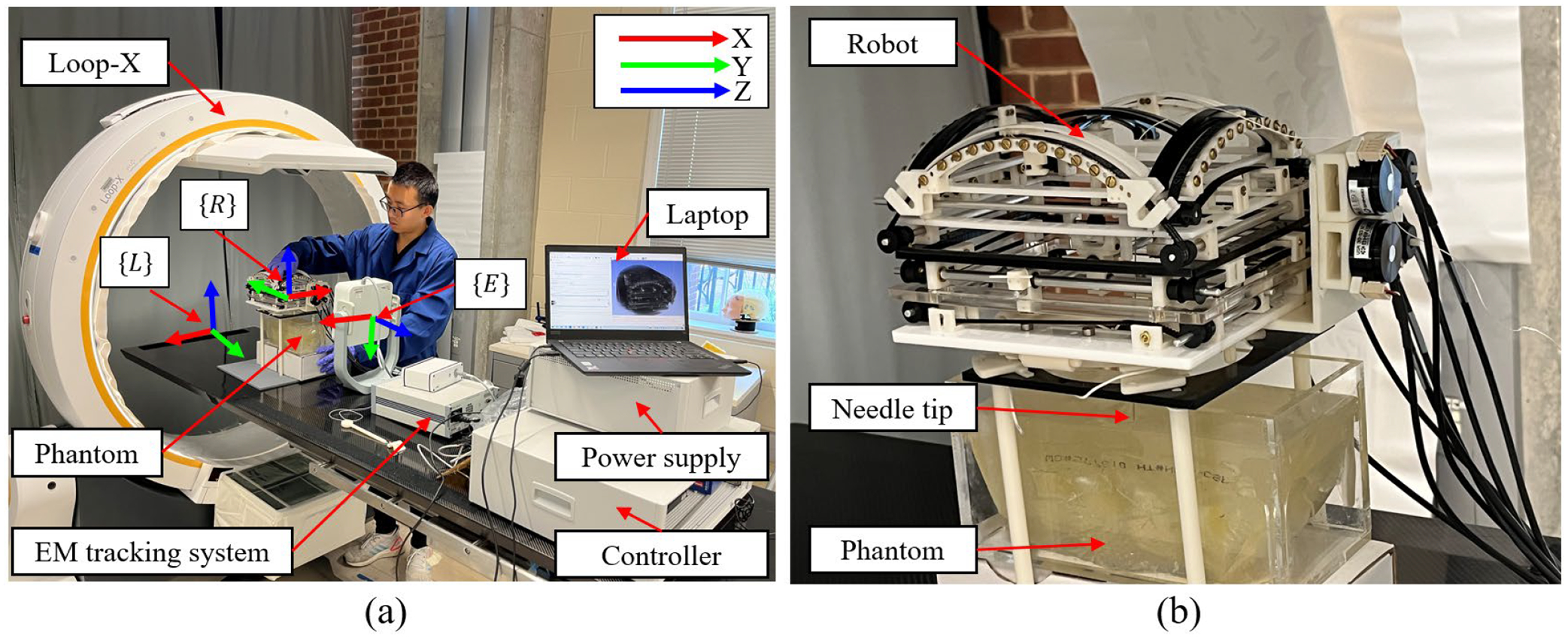
Phantom study experimental setup. (a) The needle insertion experiment setup with a phantom. (b) Robot in the Loop-X with phantom and needle.
Figure 11.

Registration of the robot in Loop-X and EM system. (a) Fiducial frame including spherical marker shells with metal spheres inside. (b) CT scan of the fiducial frame from the Loop-X system. (c) The relationship between the Loop-X coordinate system, robot coordinate system and EM coordinate system. Points in the Loop-X coordinate system and the EM coordinate system undergo transformations for use in the robot coordinate system.
Figure 12.

Needle insertion process in Loop-X. (a) The needle tip reaches the entry point. (b) The needle tip reaches the target point. (c) One case shown the needle deformation.
Figure 13.

Image-guided phantom study results. (a) 10 Entry points and target point shown in 3D Slicer. (b) Position errors of the entry point and target point (Unit: mm).
To determine the position of the robot within the Loop-X, we designed a fiducial frame which included four cylindrical marker shells with metal spheres inside, so tracking could be done with the EM tracking system. We used MRI visible fiducial markers [48] when the robot was in the MRI environment. During the registration process, two center points of the metal spheres were manually selected on each marker shell (eight points in total) from to in 3D Slicer shown in Fig. 11 (a) and Fig. 11 (b). The points to are horizontally configured with respect to the fiducial frame and are easily visualized in Fig. 11 (b), however and are vertically configured and are not both visible in Fig. 11 (b). The positions of these eight points in EM coordinate system need to be obtained using a calibration stylus with EM system coil shown in Fig. 11 (a), to obtain their locations with respect to the Loop-X coordinate system. Since the positions of these eight points in the robot coordinate system were already known, we can determine the transformation matrix between the Loop-X coordinates, EM coordinates, and the robot’s coordinates using equations (15) to (17). The Loop-X coordinate system, robot coordinate system and EM coordinate system are shown in Fig. 10 (a) denoted as , and , , respectively. and are transformation matrices, and their relationship is shown in Fig. 11 (c). Marking eight points constituted a complete registration process, and this process was repeated 10 times. Then and errors were found to be 0.21 ± 0.12 mm and 0.12 ± 0.08 mm, respectively. We used the same method here as we used previously in [49] to register the robot on the EM tracking system with the calibration stylus shown in Fig. 11 (a).
| (15) |
| (16) |
| (17) |
As shown in Fig. 12, the error of the entry point is defined as the distance between the theoretical entry point and the actual entry point. The error of the target point is defined as the distance between the theoretical target point and the actual target point. Based on the results from the phantom study in Fig. 13, the mean positioning accuracy of the entry point is 1.53 ± 0.55 mm. The positioning accuracy for the target is 3.62 ± 0.92 mm.
IV. Discussion
After verification, the robot’s linear motion ranges are X = ± 40 mm, Y = ± 60 mm, and rotary motion ranges are RX = ± 35°, RY = ± 35°. The volume of the robot is 200 × 230 × 130 mm3 with a mass of 0.8 kg. These parameters are in accordance with the design requirements. Analyzing the single axis precision from Fig. 8, the errors and standard deviations of RX, RY, X, Y are as follows: 0.13° ± 0.09°, 0.19° ± 0.34°, 0.09 ± 0.11 mm, 0.62 ± 0.69 mm, respectively. In both linear and rotational motions relative to the Y axis, it is observed that the errors are smaller and more stable along the X axis. Furthermore, the standard deviation of RY, which is 0.34°, is greater than the average error 0.19°. This indicates dispersion or inconsistency relative to the mean value, suggesting variability or inconsistency in the measurements.
The reason for this inconsistency might be due to the triggering time difference of the limit switch. As in our previous research, we measured the accuracy of the limit switches to be 0.42 ± 0.25 mm [50]. Since we utilize photoelectric limit switches and our experiment employs a relative measurement approach, every single-axis measurement starts with the triggering point of the limit switch as the initial measurement reference. Therefore, if the triggering position of the limit switch was inconsistent from the start, the position displayed in the EM system would differ, leading to systematic offset issues in the measurements of the same point on the same axis. Another possible reason might be mechanical issues within the robot such as improper installation of the bearing, Improper installation could potentially lead to an uneven force distribution between the Y axis and the bearing, increasing friction and resulting in the Y axis experiencing jamming during movement.
The experimental results shown in Fig. 9 demonstrated that the positioning accuracy is at the sub-millimeter level, which is on par with our previous research results. The previous needle angle accuracy was 0.70° ± 0.38°, and the previous needle tip position accuracy was 0.51 ± 0.27 mm) [38].
As we can see from Fig. 13, the mean positioning accuracy of the entry point is 1.53 ± 0.55 mm. Although this does not match the localization accuracy in free space, it is acceptable considering that the experiments conducted in Loop-X introduced registration error of up to 1.00 ± 0.73 mm and 1.41° ± 1.06°. The localization accuracy for the target was 3.62 ± 0.92 mm, and while this met the anticipated goals, it showed a larger error compared to the entry point. A significant cause of this result is the deformation of the needle after insertion into the phantom as shown in Fig. 12 (c).
All in all, several factors contribute to the observed errors. These include potential data loss in the encoder due to misalignment or incorrect distance between components, leading to unexpected motor travel. Additionally, manufacturing and installation errors in the robot parts, confirmed by free space measurements, may also play a role.
Compared to previous studies [37–40], this design offers several notable advantages. The robot described in this article incorporates two platforms. By utilizing a spherical guide rail design, the change in distance between the two platforms during robot motion is reduced. Additionally, the actual rotational range is increased from ± 25° to ± 35°. Furthermore, during both translation and rotation, the motor remains fixed, preventing the wiring from shifting, which reduces tension on sensor wiring and mitigates the influence of wiring movement on MRI.
Another advantage of this study compared to previous research is the improvement in the uniformity of rotational resolution. In previous studies [40], both the upper and lower platforms were translational moving modules, leading to a nonlinear relationship (tangent relationship) between the change in needle angle and lateral movement distance when adjusting the needle’s angle. However, in this study, the implementation of a spherical guide rail for the upper platform has linearized the relationship between the change in needle angle and the distance between the two platforms. This implies that when the encoder exhibits a linear increase in readings, the angular change remains linear. Consequently, the resolution of rotation is uniformed.
This study also presents a potential advantage in that the robot can be utilized not only in MRI environment but also in CT environment. With the guidance of CT, the robot can assist surgeons in achieving more precise localization, thereby reducing the need for target searching, saving time, enhancing efficiency, and reducing ionizing radiation exposure to both surgeons and patients.
While the robot in this study possesses many advantages, it also has several limitations. First, this design involves a significant number of gears and gear transmission usually has backlash which may cause some error. Although the positioning accuracy can be corrected through encoders, the installation process can be quite cumbersome. Specifically, the encoders are installed directly on the drive shaft connected to the timing belt pulley, rather than on the motor. This arrangement effectively avoids the errors caused by backlash in the gear gearbox. The installation process of the design arises from the assembly of various independent modules such as gearboxes, four platforms, which demand high precision, particularly in installing bearings in each of the six-bearing gearboxes, out of the total four. Additionally, the intricacies involved in fitting and adjusting the timing belt in tandem with the tensioning mechanism further add to the complexity. Second, although the robot’s structure is compact and lightweight, given the widespread use of 3D-printed materials in various parts, the rigidity of this mechanical system requires further improvement. In future designs, we will consider machining components using high-strength plastics such as Polyoxymethylene (POM) to improve the rigidity of the robot system. Thirdly, while our design adheres to the same methodology as previous studies [37–40], it is imperative to conduct additional verification for the phantom study, registration process, and EMC testing under MRI environment. These works constitute essential components of our forthcoming research endeavors. We will also leverage AI techniques to perform image segmentation on MRI scans, enabling the development of automated registration algorithms. Additionally, we plan to conduct phantom and ex vivo porcine tissue studies to validate the positioning accuracy of the robot within the MRI environment.
V. Conclusion
In this study, we designed a new MR conditional robot for lumbar spinal injection based off a previous model. We utilized a needle guide, allowing for flexible adjustment of the needle’s position. Utilizing a gearbox augmented the motor’s torque output, allowing the use of smaller motors as drivers, thus making the structure more compact.
Unlike the previous design, during the updated robot’s motion, motors remained stationery and cables immobile, reducing sensor stress and potential impact on MRI. The change in distance between the two platforms during our updated robot motion was reduced. The rotational range was increased, and the rotational resolution was improved to provide uniform accuracy.
After preliminary experimental validation, the newly designed robot showed improvements and benefits in its rotation range, flexible needle adjustment, sensor protection, and reduced overall volume, compared to previous and existing systems with similar positioning accuracy levels. This signifies its potential for broader clinical applications in the future.
Acknowledgment
This work was primarily supported by the NIH through Grants 1R01 EB025179 and the Multi-Scale Medical Robotics Center in Hong Kong. The author Depeng Liu would like to express his appreciation to the National Key Research and Development Program of the Ministry of Science and Technology 2022YFC2406900, 2017YFC0108900, National Natural Science Foundation of China 81727806, 11774231, and China Scholarship Council 202106230154 for their valuable support.
Footnotes
Conflict of interest disclosure
The authors affirm that the research presented has no personal, professional, or financial ties that might be construed as a potential conflict of interest.
References
- [1].Koes BW, Van Tulder M, & Thomas S (2006). Diagnosis and treatment of low back pain. Bmj, 332(7555), 1430–1434. [DOI] [PMC free article] [PubMed] [Google Scholar]
- [2].Hestbaek L, Leboeuf-Yde C, Kyvik KO, & Manniche C (2003). Is low back pain in youth associated with weight at birth? A cohort study of 8000 Danish adolescents. Danish medical bulletin, 50(2), 181–185. [PubMed] [Google Scholar]
- [3].Petit A, & Roquelaure Y (2015). Low back pain, intervertebral disc and occupational diseases. International Journal of Occupational Safety and Ergonomics, 21(1), 15–19. [DOI] [PubMed] [Google Scholar]
- [4].Johanning E (2000). Evaluation and management of occupational low back disorders. American journal of industrial medicine, 37(1), 94–111. [DOI] [PubMed] [Google Scholar]
- [5].Miedema HS, van der Molen HF, Kuijer PP, Koes BW, & Burdorf A (2014). Incidence of low back pain related occupational diseases in the N etherlands. European Journal of Pain, 18(6), 873–882. [DOI] [PubMed] [Google Scholar]
- [6].Shan Z, Deng G, Li J, Li Y, Zhang Y, & Zhao Q (2013). Correlational analysis of neck/shoulder pain and low back pain with the use of digital products, physical activity and psychological status among adolescents in Shanghai. Plos one, 8(10), e78109. [DOI] [PMC free article] [PubMed] [Google Scholar]
- [7].Lilje SC, Olander E, Berglund J, Skillgate E, & Anderberg P (2017). Experiences of older adults with mobile phone text messaging as reminders of home exercises after specialized manual therapy for recurrent low back pain: a qualitative study. JMIR mHealth and uHealth, 5(3), e7184. [DOI] [PMC free article] [PubMed] [Google Scholar]
- [8].Maher CG (2004). Effective physical treatment for chronic low back pain. Orthopedic Clinics, 35(1), 57–64. [DOI] [PubMed] [Google Scholar]
- [9].Shipton EA (2018). Physical therapy approaches in the treatment of low back pain. Pain and therapy, 7, 127–137. [DOI] [PMC free article] [PubMed] [Google Scholar]
- [10].DeRosa CP, & Porterfield JA (1992). A physical therapy model for the treatment of low back pain. Physical Therapy, 72(4), 261–269. [DOI] [PubMed] [Google Scholar]
- [11].Enthoven WT, Roelofs PD, Deyo RA, van Tulder MW, Koes BW, & Cochrane Back and Neck Group. (1996). Non-steroidal anti-inflammatory drugs for chronic low back pain. Cochrane Database of Systematic Reviews, 2016(8). [DOI] [PMC free article] [PubMed] [Google Scholar]
- [12].Kuritzky L, & Samraj GP (2012). Nonsteroidal anti-inflammatory drugs in the treatment of low back pain. Journal of pain research, 579–590. [DOI] [PMC free article] [PubMed] [Google Scholar]
- [13].Roelofs PD, Deyo RA, Koes BW, Scholten RJ, & van Tulder MW (2008). Non-steroidal anti-inflammatory drugs for low back pain. Cochrane database of systematic reviews, (1). [DOI] [PMC free article] [PubMed] [Google Scholar]
- [14].Rivera CE (2018). Lumbar epidural steroid injections. Physical Medicine and Rehabilitation Clinics, 29(1), 73–92. [DOI] [PubMed] [Google Scholar]
- [15].Ackerman WE III, & Ahmad M (2007). The efficacy of lumbar epidural steroid injections in patients with lumbar disc herniations. Anesthesia & Analgesia, 104(5), 1217–1222. [DOI] [PubMed] [Google Scholar]
- [16].Cannon DT, & Aprill CN (2000). Lumbosacral epidural steroid injections. Archives of physical medicine and rehabilitation, 81(3), S87–S98. [PubMed] [Google Scholar]
- [17].Buenaventura RM, Datta S, Abdi S, & Smith HS (2009). Systematic review of therapeutic lumbar transforaminal epidural steroid injections. Pain Physician, 12(1), 233–51. [PubMed] [Google Scholar]
- [18].Hooten WM, Mizerak A, Carns PE, & Huntoon MA (2006). Discitis after lumbar epidural corticosteroid injection: a case report and analysis of the case report literature. Pain Medicine, 7(1), 46–51. [DOI] [PubMed] [Google Scholar]
- [19].Kim SJ, Lee MH, Lee SW, Chung HW, Lee SH, & Shin MJ (2014). Radiation exposure for fluoroscopy-guided lumbosacral epidural steroid injections: comparison of the transforaminal and caudal approaches. Clinical Spine Surgery, 27(1), E37–E40. [DOI] [PubMed] [Google Scholar]
- [20].Botwin KP, Thomas S, Gruber RD, Torres FM, Bouchlas CC, Rittenberg JJ, & Rao S (2002). Radiation exposure of the spinal interventionalist performing fluoroscopically guided lumbar transforaminal epidural steroid injections. Archives of physical medicine and rehabilitation, 83(5), 697–701. [DOI] [PubMed] [Google Scholar]
- [21].Kapural L, Mekhail N, Bena J, McLain R, Tetzlaff J, Kapural M, … & Polk S (2007). Value of the magnetic resonance imaging in patients with painful lumbar spinal stenosis (LSS) undergoing lumbar epidural steroid injections. The Clinical journal of pain, 23(7), 571–575. [DOI] [PubMed] [Google Scholar]
- [22].Cohen SP, Gupta A, Strassels SA, Christo PJ, Erdek MA, Griffith SR, … & Vu TN (2012). Effect of MRI on treatment results or decision making in patients with lumbosacral radiculopathy referred for epidural steroid injections: a multicenter, randomized controlled trial. Archives of internal medicine, 172(2), 134–142. [DOI] [PubMed] [Google Scholar]
- [23].Liu D, Shen G, Tang N, Lu H, & Wei B (2023). Robotic system for magnetic resonance imaging-guided high-intensity focus ultrasound application: Feasibility of breast fibroadenoma treatment. The International Journal of Medical Robotics and Computer Assisted Surgery, e2519. [DOI] [PubMed] [Google Scholar]
- [24].Standard practice for marking medical devices and other items for safety in the magnetic resonance environment (2023). https://www.astm.org/f2503-23e01.html [DOI] [PubMed]
- [25].Su H, Kwok KW, Cleary K, Iordachita I, Cavusoglu MC, Desai JP, & Fischer GS (2022). State of the art and future opportunities in MRI-guided robot-assisted surgery and interventions. Proceedings of the IEEE, 110(7), 968–992. [DOI] [PMC free article] [PubMed] [Google Scholar]
- [26].Xiao Q, Monfaredi R, Musa M, Cleary K, & Chen Y (2020). MR-conditional actuations: A review. Annals of Biomedical Engineering, 48, 2707–2733. [DOI] [PMC free article] [PubMed] [Google Scholar]
- [27].Kulkarni P, Sikander S, Biswas P, Frawley S, & Song SE (2019). Review of robotic needle guide systems for percutaneous intervention. Annals of biomedical engineering, 47, 2489–2513. [DOI] [PubMed] [Google Scholar]
- [28].Dehghan MR, Rezaei SM, Talebi HA, & Zareinejad M (2011). Robust high fidelity needle insertion in soft tissues implemented on a teleoperation system. IFAC Proceedings Volumes, 44(1), 344–349. [Google Scholar]
- [29].Stoianovici D, Song D, Petrisor D, Ursu D, Mazilu D, Mutener M, … & Patriciu A (2007). “MRI Stealth” robot for prostate interventions. Minimally Invasive Therapy & Allied Technologies, 16(4), 241–248. [DOI] [PMC free article] [PubMed] [Google Scholar]
- [30].Fischer GS, Iordachita I, Csoma C, Tokuda J, DiMaio SP, Tempany CM, … & Fichtinger G (2008). MRI-compatible pneumatic robot for transperineal prostate needle placement. IEEE/ASME transactions on mechatronics, 13(3), 295–305. [DOI] [PMC free article] [PubMed] [Google Scholar]
- [31].Huang S, Lou C, Xuan L, Gao H, Gao A, & Yang GZ (2022, October). A Pneumatic MR-conditional Guidewire Delivery Mechanism with Decoupled Actuations for Endovascular Intervention. In 2022 IEEE/RSJ International Conference on Intelligent Robots and Systems (IROS) (pp. 407–412). IEEE. [Google Scholar]
- [32].Wang Y, Xu Y, Kwok KW, & Iordachita I (2023, April). In Situ Flexible Needle Adjustment Towards MRI-Guided Spinal Injections Based on Finite Element Simulation. In 2023 International Symposium on Medical Robotics (ISMR) (pp. 1–7). IEEE. [DOI] [PMC free article] [PubMed] [Google Scholar]
- [33].Monfaredi R, Cleary K, & Sharma K (2018). MRI robots for needle-based interventions: systems and technology. Annals of biomedical engineering, 46, 1479–1497. [DOI] [PMC free article] [PubMed] [Google Scholar]
- [34].Su H, Zervas M, Cole GA, Furlong C, & Fischer GS (2011, May). Real-time MRI-guided needle placement robot with integrated fiber optic force sensing. In 2011 IEEE international conference on robotics and automation (pp. 1583–1588). IEEE. [Google Scholar]
- [35].Bertelsen A, Melo J, Sánchez E, & Borro D (2013). A review of surgical robots for spinal interventions. The International Journal of Medical Robotics and Computer Assisted Surgery, 9(4), 407–422. [DOI] [PubMed] [Google Scholar]
- [36].Huang S, Lou C, Zhou Y, He Z, Jin X, Feng Y, … & Yang GZ (2023). MRI-guided robot intervention—current state-of-the-art and new challenges. Med-X, 1(1), 4. [Google Scholar]
- [37].Li G, Patel NA, Sharma K, Monfaredi R, Dumoulin C, Fritz J, … & Cleary K (2020). Body-mounted robotics for interventional MRI procedures. IEEE transactions on medical robotics and bionics, 2(4), 557–560. [DOI] [PMC free article] [PubMed] [Google Scholar]
- [38].Li G, Patel NA, Liu W, Wu D, Sharma K, Cleary K, … & Iordachita I (2020, May). A fully actuated body-mounted robotic assistant for mri-guided low back pain injection. In 2020 IEEE International Conference on Robotics and Automation (ICRA) (pp. 5495–5501). IEEE. [DOI] [PMC free article] [PubMed] [Google Scholar]
- [39].Li G, Patel NA, Wang Y, Dumoulin C, Loew W, Loparo O, … & Iordachita I (2020). Fully actuated body-mounted robotic system for mri-guided lower back pain injections: Initial phantom and cadaver studies. IEEE robotics and automation letters, 5(4), 5245–5251. [DOI] [PMC free article] [PubMed] [Google Scholar]
- [40].Li G, Patel NA, Hagemeister J, Yan J, Wu D, Sharma K, … & Iordachita I (2020). Body-mounted robotic assistant for MRI-guided low back pain injection. International journal of computer assisted radiology and surgery, 15(2), 321–331. [DOI] [PMC free article] [PubMed] [Google Scholar]
- [41].Otsuka Y, An HS, Ochia RS, Andersson GB, Orías AAE, & Inoue N (2010). In vivo measurement of lumbar facet joint area in asymptomatic and chronic low back pain subjects. Spine, 35(8), 924. [DOI] [PMC free article] [PubMed] [Google Scholar]
- [42]. https://www.stratasys.com/en/contact-us/office-locations/.
- [43]. https://www.igus.com/.
- [44]. https://www.digikey.com/.
- [45]. https://www.metcaseusa.com/en.
- [46].Kikinis R, Pieper SD, & Vosburgh KG (2013). 3D Slicer: a platform for subject-specific image analysis, visualization, and clinical support. In Intraoperative imaging and image-guided therapy (pp. 277–289). New York, NY: Springer New York. [Google Scholar]
- [47].Lasso A, Heffter T, Rankin A, Pinter C, Ungi T, & Fichtinger G (2014). PLUS: open-source toolkit for ultrasound-guided intervention systems. IEEE transactions on biomedical engineering, 61(10), 2527–2537. [DOI] [PMC free article] [PubMed] [Google Scholar]
- [48].Tokuda J, Song SE, Tuncali K, Tempany C, & Hata N (2013). Configurable automatic detection and registration of fiducial frames for device-to-image registration in MRI-guided prostate interventions. In Medical Image Computing and Computer-Assisted Intervention–MICCAI 2013: 16th International Conference, Nagoya, Japan, September 22–26, 2013, Proceedings, Part III 16 (pp. 355–362). Springer Berlin Heidelberg. [DOI] [PMC free article] [PubMed] [Google Scholar]
- [49].Connolly L, Deguet A, Sunderland K, Lasso A, Ungi T, Rudan JF, … & Fichtinger G (2021, August). An open-source platform for cooperative, semi-autonomous robotic surgery. In 2021 IEEE International Conference on Autonomous Systems (ICAS) (pp. 1–5). IEEE. [Google Scholar]
- [50].Patel NA, Yan J, Levi D, Monfaredi R, Cleary K, & Iordachita I (2018, October). Body-mounted robot for image-guided percutaneous interventions: mechanical design and preliminary accuracy evaluation. In 2018 IEEE/RSJ International Conference on Intelligent Robots and Systems (IROS) (pp. 1443–1448). IEEE. [DOI] [PMC free article] [PubMed] [Google Scholar]