

Abstract
We propose a novel inexpensive embedded capacitive sensor (ECS) for sensing the shape of Continuum Dexterous Manipulators (CDMs). Our approach addresses some limitations associated with the prevalent Fiber Bragg Grating (FBG) sensors, such as temperature sensitivity and high production costs. ECSs are calibrated using a vision-based system. The calibration of the ECS is performed by a recurrent neural network that uses the kinematic data collected from the vision-based system along with the uncalibrated data from ECSs. We evaluated the performance on a 3D printed prototype of a cable-driven CDM with multiple markers along its length. Using data from three ECSs along the length of the CDM, we computed the angle and position of its tip with respect to its base and compared the results to the measurements of the visual-based system. We found a 6.6% tip position error normalized to the length of the CDM. The work shows the early feasibility of using ECSs for shape sensing and feedback control of CDMs and discusses potential future improvements.
Index Terms: continuum dexterous manipulators, shape estimation, capacitive sensing
I. Introduction
Continuum dexterous manipulators (CDMs) have gained significant traction in surgical systems due to their inherent dexterity and enhanced accessibility, which greatly contribute to the advancement of minimally invasive surgery techniques [1]–[3]. However, the inherent compliance and varying dynamic environment encountered during the surgery, present challenges in developing models for intraoperative real-time control of the CDM motion.
Medical imaging techniques, such as fluoroscopic imaging, can be utilized to estimate the shape of CDMs during procedures [4]. Fiber Bragg Grating (FBG) sensors are commonly employed for shape sensing in CDMs due to their compact size and efficient strain transfer [2], [5]–[8]. However, FBG sensors exhibit cross-sensitivity to strain and temperature, necessitating additional temperature compensation when the environment’s temperature changes [9]. Moreover, FBG sensors require costly and sophisticated interrogators to accurately monitor the Bragg wavelength’s position [10].
Capacitance sensing is a widely employed method for embedded shape sensing, particularly in the field of soft robotics [11]–[13]. This sensing technique enables the measurement of shape without being affected by issues such as occlusion and coordinate transformation [12]. However, to our knowledge, the utilization of embedded capacitance sensors for shape sensing in CDMs has not been extensively explored in the existing literature.
We propose an ECS design to be later miniaturized and used for minimally-invasive surgery. The sensor strip, composed of copper foil encapsulated in polyester films, is embedded in the walls of the CDM. The ECS senses shape changes based on the relative area variation between the strips during bending. This sensor demonstrates reliable performance in varying temperature environments, addressing the challenges of temperature fluctuations in orthopedic surgery when the CDM is used to drill and mill hard tissues [2]. Moreover, the proposed ECS design is easily replaceable and does not rely on costly interrogators, making it a practical and inexpensive solution for CDM shape sensing. The contributions of this work are as follows:
Introducing a novel capacitor strip design for CDM shape sensing.
Developing a vision-based pipeline and implementing an ECS calibration method utilizing deep learning.
II. Design, Fabrication, and Calibration
A. Sensor Design and Fabrication
The capacitance sensor assembly, as depicted in Figure 1(a), consists of five layers: coverfilm, adhesive layer, metal layer, insulation layer, metal layer, and coverfilm.These layers are designed to ensure the physical integrity of the sensor and enable accurate capacitance measurements. The coverfilm serves as a protective package for the ECS and is made of a 3-mil (0.0762 mm) lamination film. It provides the necessary tensile force to maintain the integrity of the ECS strips within the CDM, preventing misreadings caused by irreversible bending. The copper foil in each stripe serves as the basis of the ECS, with the capacitors formed between neighboring copper foils. This allows us to detect the capacitance, which provides valuable information about the shape and bending of the CDM. The insulation layer in the ECS strip ensures proper separation between the capacitors, preventing any interference or crosstalk between them. The adhesive layer is applied to enhance the overall fabrication quality and minimize the risk of ECS malfunction due to broken wires or separated packages.
Fig. 1.

Fabrication of sensor structures for capacitive shape sensing in CDMs. (a) The Signal layers serve as primary components for ascertaining both the direction and degree of bending. (b) Depiction of the relative positions of copper plates within the sensor, functioning as carriers of signal and ground. This subfigure illustrates the specific sensor locations where the strips establish their connections.
Three sets of sensor assemblies are positioned at different locations to eliminate interference, as depicted in Fig. 1(b). As the CDM bends, the overlayed area of the capacitance surface undergoes changes. By measuring the differential change in capacitance between the opposing sides of the CDM, the direction and magnitude of the bending can be determined.
B. Sensor Calibration and Shape Reconstrction
To achieve CDM shape detection using a camera, we have devised a system calibration algorithm that addresses the transformation and scaling issues of the image projection. This algorithm leverages four calibration points, as depicted in Figure 2(a), to determine their corresponding positions in the image frame. By employing a least squares approach, we minimize the projection error and establish a mapping between the image frame and the real positions in the horizontal frame. Furthermore, we apply a ratio compensation technique to rectify any scaling discrepancies between the image of the horizontal plane and the bending plane. This allows us to accurately determine the positions of the markers on the bending plane, facilitating precise shape sensing of the CDM. Through the calibration process, we achieved submillimeter error between the CDM tip and the base portion across the entire workspace.
Fig. 2.

The CDM pose tracking and calibration pipeline: (a) RGB image captured, with the orientation and ratio calibrated by mapping the four red points to their respective positions. (b) CDM joint position tracking achieved using an HSV color filter. (c) Collection of capacitance readings from the capacitors. (d) Plot showing the relationship between capacitance values and tip bending angles. The capacitance gap indicates a dependence on previous CDM states. (e) Structure of the RNN (Recurrent Neural Network) with a sequence length of 10. (f) Result of shape regeneration using the RNN output values.
Following the completion of the system calibration, we are able to track the positions of 28 markers, using a Hue Saturation and Value (HSV) color filter, as demonstrated in Fig 2(b). This approach allows for real-time tracking of the marker positions, the corresponding capacitor values are also recorded alongside the positions with corresponding timestamps.
In this study, the CDM is represented as a kinematic chain, where the configuration of the CDM is described by a sequence of joint angles that correspond to the angles between adjacent segments. The joint angles are computed by determining the intersection of lines connecting neighboring markers with the y-axis which is along the base of the CDM. Additionally, the segment lengths are calculated as the Euclidean distances between the markers. For the purpose of sensor calibration, we utilize the average segment length as a kinematic parameter, and the joint angles serve as inputs for the calibration process. The relationship between the tip angle and the top capacitor value is displayed in Fig. 2(d).
Due to the presence of the capacitor gap phenomenon depicted in Fig. 2(d), it is not feasible to describe the mapping between capacitance and joints angles using linear regression. To address this, we employed a recurrent neural network (RNN)-based model to calibrate the sensor, as illustrated in Fig. 2(e). The RNN model takes into account the temporal correlation in the data, allowing for improved calibration performance compared to linear regression methods.
Finally, we developed a Robot Operating System 2 (ROS2) package to reconstruct the calculated CDM shape in real-time and visualize it using RViz - a kinematic simulation package. This integration allows for the representation of the CDMs’ shape, as shown in Fig 2(f).
III. Experiments and Results
To calibrate the developed ECS and evaluate its shape sensing capabilities, we devised an experimental procedure comprising of the following steps: system setup and calibration, data collection, ECS calibration, and result analysis. In this section, we provide a detailed overview of each step, discussing the methodologies employed and the specific procedures undertaken to ensure a thorough evaluation and analysis of the capacitor sensor’s performance.
A. System Setup and Calibration
To evaluate the performance of the capacitor sensor on CDMs, we integrated the ECS strips into a 3D-printed prototype, as depicted in Figure 1. The CDM prototype has a total length of 225.0 mm, with a bendable part length of 101.9 mm. In order to maintain consistent and accurate measurements, the CDM is securely fixed to a horizontal flat plane using a 3D-printed fixture. This ensures that the bending plane of the CDM aligns parallel to the horizontal plane, enabling reliable shape sensing experiments.
CDM shape is captured using a Realsense D435i camera, securely fixed with a camera holder. System calibration and ratio compensation methods, discussed in Section II.B, enable precise determination of the positions of CDM points on the bending plane from the captured images.
B. Data Collection
After completing the system calibration, the positions of the CDM joints can be accurately captured on the bending plane. The capacitance values, obtained through the AD7747 capacitance-to-digital converter and Arduino Mega 2560, are processed in real-time. This integrated system enables simultaneous data collection of the joint positions and capacitance.
The CDM is bent using its embedded cables. The maximum bending angle between the CDM’s tip and its base is approximately 68°, and the bending angle and duration of each bend vary. Throughout the bending process, the capacitor values and joint positions are recorded and stored in CSV files. A total of 1314 data points have been collected in the database, providing a comprehensive dataset for analysis and evaluation.
C. Sensor Calibration Model and Results
Due to the observed correlation in the acquired data, we investigated the use of RNN as a suitable model for sensor calibration. In addition to RNN, we also employed two other regression models for comparison: linear regression and linear regression with a kernel (measuring the difference in capacitance between two consecutive states).
The evaluation criteria consist of four error metrics: average angle error, average position error, tip angle error, and tip position error. The average angle error represents the mean discrepancy between the predicted and measured joint angles. Similarly, the average position error quantifies the mean difference between the predicted and measured joint positions. The tip angle error measures the mean error between the predicted and measured bending angles at the CDM tip, while the tip position error assesses the mean difference between the predicted and measured positions of the CDM tip. Angle errors are obtained directly from the regression model, while position errors are calculated using forward kinematics based on a kinematics model established using average distance data from the vision module.
The RNN model was trained using a learning rate of 1.0 × 10⁻³ and a batch size of 32. The architecture of the model includes two recurrent layers, with 3 nodes in the input layer, 128 nodes in the hidden layer, and 28 nodes in the output layer. The sequence length for input data is set to 10. The optimization process utilizes the Adam optimizer, and the training is performed for 200 epochs. The mean absolute error (MAE) is used as the loss function to evaluate the predicted angles of the joints. Fig. 3 displays the training and validation errors, indicating that the model is effectively trained and achieves convergence within 200 epochs.
Fig. 3.
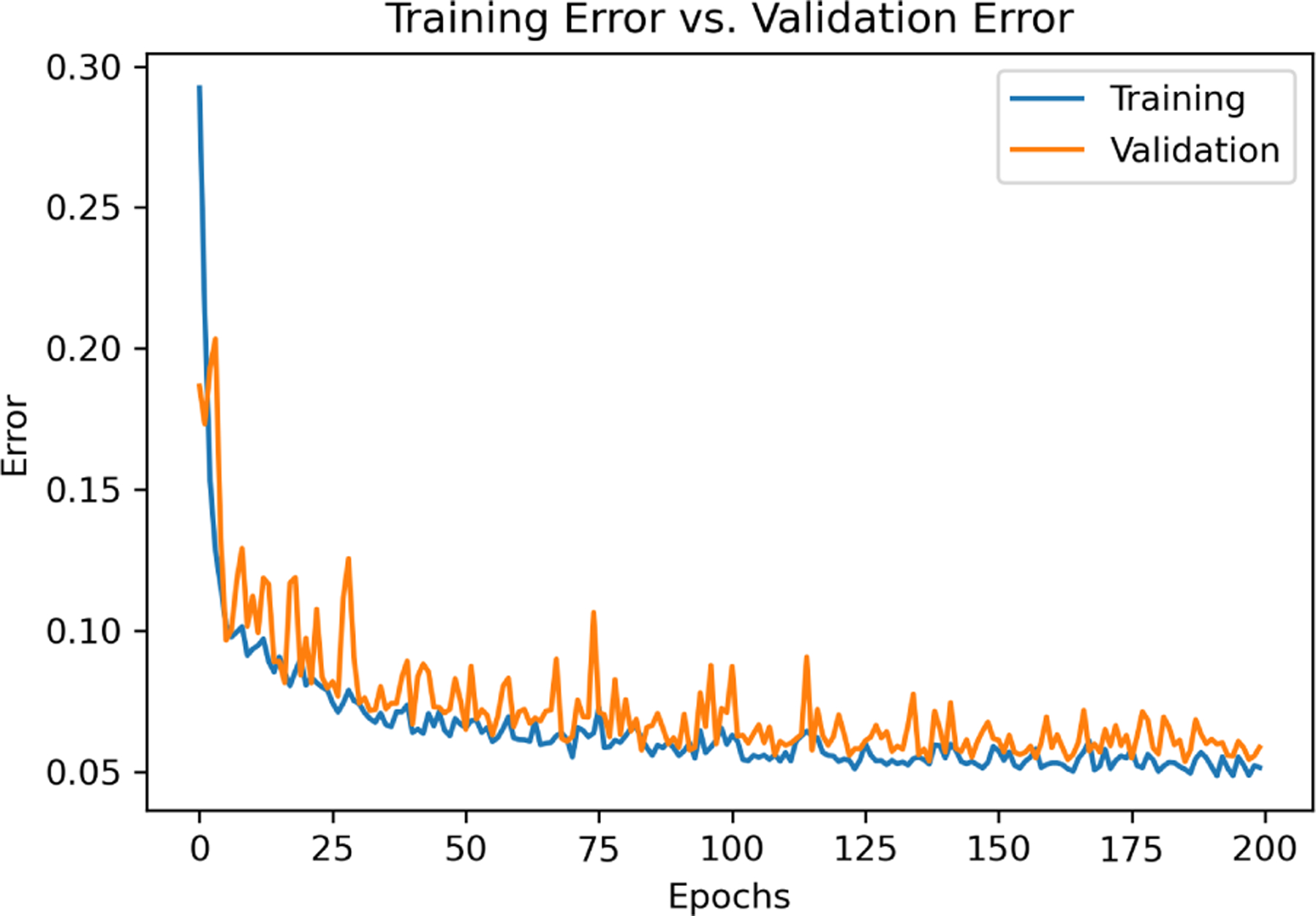
Training and validation error plotted against epochs.
The trained model is tested on the testing dataset to calculate the predicted angles. The error between the predicted and measured angles is computed, and the predicted angles are used in the kinematics model to determine the position error for each joint. The results are summarized in Table I.
TABLE I.
Calibration Model Comparison
| Error | Linear Regression | Kernel Regression | RNN |
|---|---|---|---|
| avg. Angle (degree) | 6.0 | 5.1 | 3.9 |
| avg. Position (mm) | 3.4 | 2.8 | 2.2 |
| Tip Angle (degree) | 11.1 | 9.0 | 7.4 |
| Tip Position (mm) | 9.6 | 7.8 | 6.7 |
The results presented in Table I demonstrate that the RNN model achieved a lower percentage error in both tip angle (33.33%) and tip position (30.21%) compared to the linear regression model. This indicates the superior performance of the RNN model in capturing the time-series properties of ECS and highlights its effectiveness for accurate sensor calibration. The improvement observed in the linear regression model with a kernel further validates the importance of considering the time-series nature of the sensor data. These findings emphasize the suitability of RNNs for achieving enhanced performance and accurate calibration in capacitor shape sensing applications.
IV. Conclusion
This work demonstrates the feasibility of using the capacitive sensor assembly for shape determination of CDMs. Through a vision-based sensor calibration pipeline, we achieved a shape reconstruction model with a tip distance error of 6.7 mm and a tip angle error of 7.4°. However, when normalized to the length of the CDM, the resulting 6.5% error remains higher than the reported tip position error estimations for embedded FBG sensors [14], [15]. Future optimization of the ECS design may lead to comparable CDM tip position errors as those achieved with embedded FBG sensors.
We also intend to miniaturize the capacitor strips and integrate them into the CDMs with a reduced outer diameter of 6 mm. Exploring the use of liquid metal in capacitor or resistance strips holds promise for further advancements in this area.
Acknowledgments
This work was funded by NIH R01-EB016703 and NIH R01-AR080315.
References
- [1].Burgner-Kahrs J, Rucker DC, and Choset H, “Continuum Robots for Medical Applications: A Survey,” IEEE Transactions on Robotics, vol. 31, no. 6, pp. 1261–1280, Dec. 2015. [Online]. Available: https://ieeexplore.ieee.org/document/7314984/ [Google Scholar]
- [2].Sefati S, Hegeman R, Iordachita I, Taylor RH, and Armand M, “A Dexterous Robotic System for Autonomous Debridement of Osteolytic Bone Lesions in Confined Spaces: Human Cadaver Studies,” IEEE Transactions on Robotics, vol. 38, no. 2, pp. 1213–1229, Apr. 2022. [Online]. Available: https://ieeexplore.ieee.org/document/9492035/ [DOI] [PMC free article] [PubMed] [Google Scholar]
- [3].Ma JH, Sefati S, Taylor RH, and Armand M, “An Active Steering Hand-Held Robotic System for Minimally Invasive Orthopaedic Surgery Using a Continuum Manipulator,” IEEE Robotics and Automation Letters, vol. 6, no. 2, pp. 1622–1629, Apr. 2021. [Online]. Available: https://ieeexplore.ieee.org/document/9354899/ [DOI] [PMC free article] [PubMed] [Google Scholar]
- [4].Gao C, Phalen H, Sefati S, Ma J, Taylor RH, Unberath M, and Armand M, “Fluoroscopic Navigation for a Surgical Robotic System Including a Continuum Manipulator,” IEEE Transactions on Biomedical Engineering, vol. 69, no. 1, pp. 453–464, Jan. 2022, conference Name: IEEE Transactions on Biomedical Engineering. [DOI] [PMC free article] [PubMed] [Google Scholar]
- [5].Shi C, Luo X, Qi P, Li T, Song S, Najdovski Z, Fukuda T, and Ren H, “Shape Sensing Techniques for Continuum Robots in Minimally Invasive Surgery: A Survey,” IEEE Transactions on Biomedical Engineering, vol. 64, no. 8, pp. 1665–1678, Aug. 2017. [Online]. Available: http://ieeexplore.ieee.org/document/7723875/ [DOI] [PubMed] [Google Scholar]
- [6].Abushagur A, Arsad N, Reaz M, and Bakar A, “Advances in Bio-Tactile Sensors for Minimally Invasive Surgery Using the Fibre Bragg Grating Force Sensor Technique: A Survey,” Sensors, vol. 14, no. 4, pp. 6633–6665, Apr. 2014. [Online]. Available: http://www.mdpi.com/1424-8220/14/4/6633 [DOI] [PMC free article] [PubMed] [Google Scholar]
- [7].Liu H, Farvardin A, Pedram SA, Iordachita I, Taylor RH, and Armand M, “Large Deflection Shape Sensing of a Continuum Manipulator for Minimally-Invasive Surgery,” IEEE International Conference on Robotics and Automation : ICRA : [proceedings] IEEE International Conference on Robotics and Automation, vol. 2015, pp. 201–206, May 2015. [Online]. Available: https://www.ncbi.nlm.nih.gov/pmc/articles/PMC4547476/ [DOI] [PMC free article] [PubMed] [Google Scholar]
- [8].Amirkhani G, Goodridge A, Esfandiari M, Phalen H, Ma JH, Iordachita I, and Armand M, “Design and Fabrication of a Fiber Bragg Grating Shape Sensor for Shape Reconstruction of a Continuum Manipulator,” IEEE Sensors Journal, pp. 1–1, 2023, conference Name: IEEE Sensors Journal. [DOI] [PMC free article] [PubMed]
- [9].Han G.-h. and Zhang W.-g., “Method of correlation function for analyzing cross-sensitivity of strain and temperature in fiber grating sensors,” Optoelectronics Letters, vol. 3, no. 3, pp. 195–198, May 2007. [Online]. Available: 10.1007/s11801-007-6166-4 [DOI] [Google Scholar]
- [10].Flores-Bravo JA, Madrigal J, Zubia J, Sales S, and Villatoro J, “Coupled-core fiber Bragg gratings for low-cost sensing,” Scientific Reports, vol. 12, no. 1, p. 1280, Jan. 2022, number: 1 Publisher: Nature Publishing Group. [Online]. Available: https://www.nature.com/articles/s41598-022-05313-9 [DOI] [PMC free article] [PubMed] [Google Scholar]
- [11].Johnson WR, Agrawala A, Huang X, Booth J, and Kramer-Bottiglio R, “Sensor Tendons for Soft Robot Shape Estimation,” in 2022 IEEE Sensors Dallas, TX, USA: IEEE, Oct. 2022, pp. 1–4. [Online]. Available: https://ieeexplore.ieee.org/document/9967136/ [Google Scholar]
- [12].Thuruthel TG, Shih B, Laschi C, and Tolley MT, “Soft robot perception using embedded soft sensors and recurrent neural networks,” Science Robotics, vol. 4, no. 26, p. eaav1488, Jan. 2019. [Online]. Available: 10.1126/scirobotics.aav1488 [DOI] [PubMed] [Google Scholar]
- [13].Hu D, Giorgio-Serchi F, Zhang S, and Yang Y, “Stretchable e-skin and transformer enable high-resolution morphological reconstruction for soft robots,” Nature Machine Intelligence, vol. 5, no. 3, pp. 261–272, Feb. 2023. [Online]. Available: https://www.nature.com/articles/s42256-023-00622-8 [Google Scholar]
- [14].Sefati S, Gao C, Iordachita I, Taylor RH, and Armand M, “Data-Driven Shape Sensing of a Surgical Continuum Manipulator Using an Uncalibrated Fiber Bragg Grating Sensor,” IEEE Sensors Journal, vol. 21, no. 3, pp. 3066–3076, Feb. 2021. [Online]. Available: https://ieeexplore.ieee.org/document/9210547/ [DOI] [PMC free article] [PubMed] [Google Scholar]
- [15].Sefati S, Hegeman R, Alambeigi F, Iordachita I, and Armand M, “FBG-Based Position Estimation of Highly Deformable Continuum Manipulators: Model-Dependent vs. Data-Driven Approaches,” in 2019 International Symposium on Medical Robotics (ISMR). Atlanta, GA, USA: IEEE, Apr. 2019, pp. 1–6. [Online]. Available: https://ieeexplore.ieee.org/document/8710179/ [Google Scholar]