Abstract
Introduction
With recent advancements in deep brain stimulation (DBS), directional leads featuring segmented contacts have been introduced, allowing for targeted stimulation of specific brain regions. Given that manufacturers employ diverse markers for lead orientation, our investigation focuses on the adaptability of the 2017 techniques proposed by the Cologne research group for lead orientation determination.
Methods
We tailored the two separate 2D and 3D X-ray-based techniques published in 2017 and originally developed for C-shaped markers, to the dual-marker of the Medtronic SenSight™ lead. In a retrospective patient study, we evaluated their feasibility and consistency by comparing the degree of agreement between the two methods.
Results
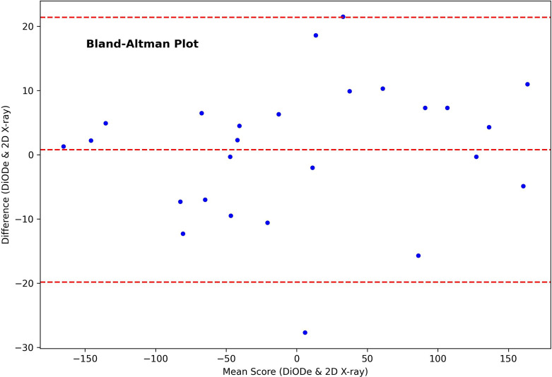
The Bland-Altman plot showed favorable concordance without any noticeable systematic errors. The mean difference was 0.79°, with limits of agreement spanning from 21.4° to −19.8°. The algorithms demonstrated high reliability, evidenced by an intraclass correlation coefficient of 0.99 (p < 0.001).
Conclusion
The 2D and 3D algorithms, initially formulated for discerning the circular orientation of a C-shaped marker, were adapted to the marker of the Medtronic SenSight™ lead. Statistical analyses revealed a significant level of agreement between the two methods. Our findings highlight the adaptability of these algorithms to different markers, achievable through both low-dose intraoperative 2D X-ray imaging and standard CT imaging.
Keywords: Deep brain stimulation, Directional deep brain stimulation, Directional leads, Segmented electrodes, Axial steering, Orientation angle
Introduction
Deep brain stimulation (DBS) is a well-established technique in neuromodulation, effectively mitigating symptoms across various diseases [1]. Traditionally, only symmetrical, spherical stimulation at differentiated intensities was achievable. Nonetheless, advancements in recent years have ushered in directed stimulation, oriented perpendicular to the lead [2–5]. Such innovation enables more precise tailoring of the stimulation volume to the target region, thereby reducing potential implantation inaccuracies and the effects of an anisotropic medium [6]. To synchronize directed stimulation with local MR or atlas anatomy – a strategy showing promise [7–10] – leads are fitted with X-ray opaque markers to denote contact orientation [11–14]. However, the use of proprietary markers by different manufacturers introduces complexities in standardization. In a notable advancement in 2021, Medtronic launched the SenSight™ directional lead, a significant innovation in the field. This device uniquely combines stimulation functionalities with the capability to record local field potentials, may be marking a pivotal step forward in the precision and versatility of deep brain stimulation technologies.
Our study illustrates the adaptability of the 2D X-ray projection-based and 3D Computed Tomography (CT) Directional Orientation Detection (DiODe) algorithm published in 2017 by the Cologne research group [11]. Originally devised for Boston Scientific’s and Abbott’s C-shaped marker to determine circular orientation, we demonstrate its modification to cater to the distinctly designed bimodal marker of the Medtronic SenSight™ lead. This algorithm’s universal applicability underwent thorough assessment using both phantom and patient data.
Materials and Methods
Medtronic SenSight™ DBS Lead
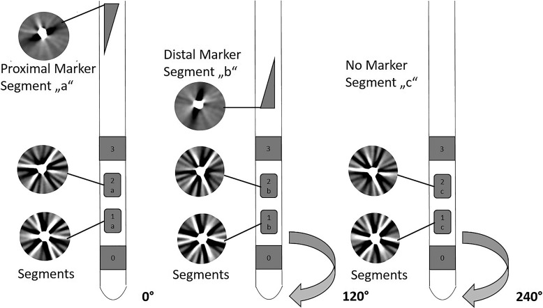
Figure 1 provides a schematic representation of the SenSight™ lead from Medtronic. The lead features eight stimulation poles distributed across four tiers with a configuration of 1-3-3-1 contacts. The central two tiers enable directional stimulation by segmenting the contact into designated sections: “a,” “b,” and “c.” Two radiopaque markers, positioned above the contacts, facilitate the determination of the lead’s circular orientation. The proximal marker is triangular, pointing towards segment “a,” while the distal triangular marker indicates segment “b.”
Fig. 1.
Illustration of the SenSight™ lead and the CT streak artefacts (superimposed circles) observed at the marker levels and used for the orientation detection.
Marker Orientation
We modified two distinct algorithms in [11]: one based on a pair of 2D X-ray projection images (shown in Fig. 2) and the other on 3D CT imaging (shown in Fig. 1), to determine the orientation of the SenSight™ marker. The lead’s position and marker orientation, along with the contacts, are defined using a right-handed coordinate system (x, y, z). The three-dimensional orientation encompasses pitch (rotation around the x-axis), yaw (rotation around the tilted y-axis), and roll (rotation around the lead axis). The polar angle between the lead axis and the z-axis is dictated by pitch and yaw [11]. In the subsequent sections, we will briefly outline the two algorithms and their respective adaptations.
Fig. 2.
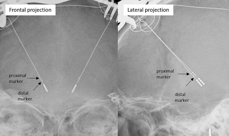
Frontal and lateral X-ray projection images of two implanted Medtronic SenSight™ leads for orientation detection.
Orientation Determination Based on 2D X-Ray Projection Images
For this algorithm, two registered orthogonal X-ray projection images are needed (shown in Fig. 2). For registration, we used the stereotactic frame and X-ray opaque localizers [15], although different 2D and 3D registration techniques are possible [16]. For estimating orientation, we generated virtual images of the marker in a full range of orientations. These images are then automatically matched with the real marker’s measured images to determine its orientation. Adapting the original algorithm required integrating the marker’s unique shape into the creation of these virtual images. Beyond this particular adjustment, the fundamental structure of the algorithm is maintained. An in-depth description of the algorithm, including its foundational concepts and functional details, is thoroughly provided in [11].
Based on 3D CT Imaging (DiODe)
In order to modify the DiODe algorithm, it is essential to consider the occurrence of two streak artifacts rather than one, as a result of the marker being constituted by a pair of triangles (shown in Fig. 1). One streak originates from the upper triangle, and the other from the lower triangle rotated by 120°. In the revised DiODe algorithm, a dual-circle approach replaces the single-circle method previously employed. These circles, each with a 3-mm radius, are defined based on signal intensities derived from CT imaging, with their centers aligned along the lead’s axis. The first circle is aligned with the upper triangle of the marker, while the second corresponds to the lower triangle. Deviating from the methodologies outlined in the original research, the orientation of the marker is not deduced via Fourier transformation of these signal intensities. Rather, a comprehensive analysis is conducted for each potential orientation angle, ranging from 1° to 360° at 1° intervals. This involves calculating the intersection points of the streak artifacts, attributable to the marker’s triangular components, with the defined circles and summing the corresponding signal intensities. The orientation of the lead is indicated by the minimum sum obtained from this analysis. Further methodological details are elaborated in [11]. Notably, the distinct 120° rotation of these streak artifacts, which are not congruent with the lead’s central axis, eliminates the ambiguity commonly encountered in orientations differing by 180°. This is a marked contrast to the C-shaped markers utilized by Boston Scientific or Abbott, which necessitate additional evaluative measures to address such ambiguities, as discussed in [17].
Assessment of Polar Angle Dependency of DiODe Algorithm
As the DiODe algorithm exhibits a dependency on the polar angle, this aspect was also examined for the SenSight™ markers. Briefly, two cylindrical phantoms, which were laboratory bottles filled with an agarose gel mixture of 13 g agar per 500 mL, were used. Two different Medtronic lead variants, featuring the same marker but different contact distances (type B33005M and B33015M), were employed for the measurements. A lead was inserted into each phantom along the cylinder axis. Each phantom was scanned multiple times with a dual-layer spectral detector CT (IQon SDCT; Philips Healthcare, Best, The Netherlands). A total of 74 CT scans were performed with different combinations of yaw, pitch, and roll angles. The polar angle varied between 0 and 60°. The scan parameters were pixel matrix 512 × 512, slice thickness 0.8 mm, field of view 310 mm, tilt 0°, helical mode, pitch factor 0.39, tube voltage 120 kV, exposure 240 mAs, and filter type UB (soft tissue). A ground truth was established using six CT measurements with the leads aligned parallel to the z-axes of the CT scanner, meaning with a polar angle nearing 0°. It was assumed that under these conditions, the circular angle for the marker could be most reliably determined due to the optimal measurement conditions with CT slices being orthogonal to the marker. Using a stylet attached to the bottle, a phantom-based coordinate system was defined. The measured circular orientations of the markers in the CT coordinate system are subsequently transferred into this new coordinate system, so that the orientation determination could be assessed in relation to the defined ground truth as a function of the polar angle.
Assessment of Agreement between 2D and 3D X-Ray Techniques
In light of the lack of a gold standard for orientation determination, we conducted a retrospective, sequential comparative study utilizing patient images. We determined the orientation of 26 leads of type B33005M, implanted in 13 patients, utilizing both methods. For the 2D X-ray projection method, we chose the final intraoperative X-ray image captured postimplantation and after the cement fixation of the leads. Meanwhile, for the CT-based determination, we used the standard postoperative CT taken a day post-surgery. To align the orientations, we transformed both into the AC-PC coordinate system. We employed a Bland-Altman plot to depict comparability and potential systematic errors and to assess whether variability between methods changes over the range of measurements. The intraclass correlation coefficient was calculated to gauge the agreement level, while a Deming regression was conducted to understand the relationship under the assumption that both methods have measurement errors. We verified normal distribution using the Shapiro-Wilk test. All statistical analyses were executed with Python 3.9.13.
Results
Polar Angle Dependency
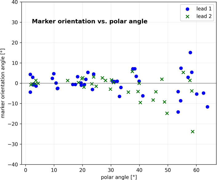
The polar angle range of the phantom measurements extended from 1.7° to 63.9°. Figure 3 shows the deviation of the determined circular orientation angles for the markers from ground truth as a function of polar angle for both leads. Up to a polar angle range of 45° an accuracy of −0.6° ± 3.4° (range: −9.5° to 5.8°) results for lead 1 and 0.6° ± 3.4° (range: −6.5° to 7.1°) for lead 2 could be achieved. From 45°, the deviations increase significantly and reach angles above ± 20° (p < 0.05).
Fig. 3.
A scatter plot representing the lead orientation with the DiODe algorithm in relation to the ground truth plotted against the polar angle.
Agreement between Both Methods
The Bland-Altman analysis of the two methods showed a mean difference of 0.8° and a standard deviation of 10.5° (shown in Fig. 4); this results in the following limits of agreement (LoA): −19.8° to 21.4°. No systematic errors can be identified.
Fig. 4.
Bland-Altman Plot of orientation determination with DiODe and 2D X-ray projection imaging.
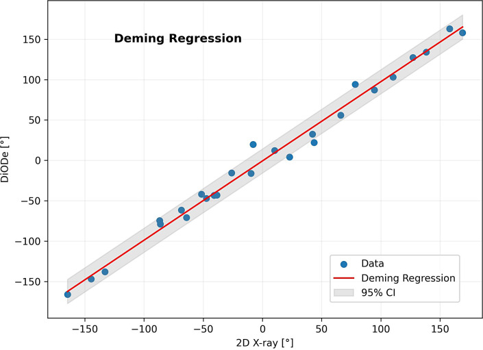
The Deming Regression results in a slope of 0.98 and an intersection point of −0.7 (shown in Fig. 5). Interclass correlation coefficient (ICC) of both methods was 0.99 (p < 0.001).
Fig. 5.
Deming regression of orientation determination with DiODe and 2D X-ray projection imaging.
Discussion
In the present study, we adapted two prevalent methods for determining the orientation of directional DBS leads with C-shaped markers by the Cologne group to the novel triangular-shaped SenSight™ lead marker by Medtronic. One method employed CT imaging, while the other used 2D X-ray projection imaging. Given the distinct nature of both methods and the absence of a gold standard, adaptations were validated by comparing results from both methods when assessing the same lead orientation. No significant difference was observed. The minimal variance between the methods suggests their high precision. This study indicates that the algorithms are compatible with common markers from Boston Scientific, Abbott, and Medtronic, emphasizing the universal applicability of these methods and algorithms. Although the fundamental principles of the algorithms remained unchanged, adaptations were essential only to accommodate the variations in marker shapes and configurations. Modifications were not required for either the CT or the 2D X-ray projection imaging procedures.
For the application of the DiODe algorithm, it is advisable to restrict the polar angle to 45° when employing the Medtronic marker and aiming for increased accuracy. This results from the diminished sensitivity of the triangular marker when compared to the C-shaped markers. Appropriate positioning of the patient can mitigate some of these limitations by aligning the lead within the required polar range.
A distinguishing characteristic of both algorithms is their resilience, even when applied to a significantly smaller marker, such as Medtronic’s, which has a considerably reduced projection surface. This marker’s orientation determination, especially with 2D X-ray projection imaging, appears more challenging than others. Image processing, particularly with the gradient filter for 2D X-ray projections, seems to play a pivotal role in this context. The DiODe algorithm’s application further underscores its versatile utility, where a minuscule edge creates a pronounced artifact, precisely delineating the edge’s orientation [18, 19]. This can be achieved with a standard CT, which is generally available everywhere and does not require any special high-resolution reconstruction. Thus, data acquired with standard CT imaging can be further evaluated. In the future, it may be possible to directly observe the orientation of the leads with the help of the new generation of photon-counting CT [20] or flat panel CT [21], without necessitating the utilization of the DiODe artifact. However, the widespread availability of these devices is still some time away, and their accuracy and precision also need to be thoroughly examined. Additionally, patients who have already been implanted and have already undergone a standard CT would need to be exposed to radiation again in order to determine the orientation using this new technique. The DiODE algorithm works with standard CT data.
Through the refinement of these algorithms, techniques have been developed for the evaluation of SenSight™ lead orientations. Notably, both the 2D and 3D techniques can be applied intraoperatively and postoperatively. However, our study primarily concentrated on an intraoperative solution for the 2D method by aligning it with the stereotactic frame utilized. Modifying the registration method would facilitate its postoperative application. The importance of postoperative electrode orientation in programming has been underscored in several studies [2–5]. The intraoperative orientation approach currently provides an improved directional derivation of field potentials during the Medtronic lead implantation compared to derivations solely made with the Percept pulse generator from Medtronic.
It is crucial to note that the CT scans, employed for this comparative study, were conducted postoperatively on the following day, indicating a 1-day interval between the two imaging modalities. Generally, significant alignment shifts after lead fixation are rare [22–24]. Should such shifts occur, they would likely lead to marked deviations, potentially underestimating the accuracy.
Conclusions
In 2017, the Cologne study group introduced two distinct algorithms for lead orientation determination: one harnessing the capabilities of 2D X-ray imaging and the other capitalizing on CT imaging. Both were meticulously adapted for the Medtronic SenSight™ lead, considering its unique marker shapes. A comparative analysis justified this customization, revealing a notable concordance between the two methods. This paper delves into the broad applicability of these algorithms, demonstrating their efficacy in determining the orientation of prevalent leads using both low-dose intraoperative 2D X-ray and standard CT imaging.
Statement of Ethics
The study is strictly retrospective. As per the Ethics Committee of the University of Cologne, there is no requirement to obtain ethics approval or informed consent from patients for this strictly retrospective study. The research was conducted in accordance with the Declaration of Helsinki and Good Clinical Practice guidelines.
Conflict of Interest Statement
T.A.D. received speaker honoraria from Medtronic GmbH. V.V.V. received support for contributions to congresses from Boston Scientific and Medtronic GmbH. The authors declare that there are no additional disclosures to report.
Funding Sources
This study was not supported by any sponsor or funder.
Author Contributions
S.H. and D.F.: conception, design, acquisition of data, statistical analysis, interpretation of data, and drafting the article and figures. A.H., M.E., J.W., T.A.D., and V.V.V.: acquisition of data, revision of the manuscript, and final approval of the version to be submitted. H.T.: conception and design, revision of the manuscript, and final approval of the version to be submitted.
Funding Statement
This study was not supported by any sponsor or funder.
Data Availability Statement
The data that support the findings of this study are not publicly available due to privacy reasons but are available from the corresponding author upon reasonable request.
References
- 1. Harmsen IE, Wolff Fernandes F, Krauss JK, Lozano AM. Where are we with deep brain stimulation? A review of scientific publications and ongoing research. Stereotact Funct Neurosurg. 2022;100(3):184–97. [DOI] [PubMed] [Google Scholar]
- 2. Contarino MF, Bour LJ, Verhagen R, Lourens MA, de Bie RM, van den Munckhof P, et al. Directional steering: a novel approach to deep brain stimulation. Neurology. 2014;83(13):1163–9. [DOI] [PubMed] [Google Scholar]
- 3. Schüpbach WMM, Chabardes S, Matthies C, Pollo C, Steigerwald F, Timmermann L, et al. Directional leads for deep brain stimulation: opportunities and challenges. Mov Disord. 2017;32(10):1371–5. [DOI] [PubMed] [Google Scholar]
- 4. Steigerwald F, Müller L, Johannes S, Matthies C, Volkmann J. Directional deep brain stimulation of the subthalamic nucleus: a pilot study using a novel neurostimulation device. Mov Disord. 2016;31(8):1240–3. [DOI] [PMC free article] [PubMed] [Google Scholar]
- 5. Pollo C, Kaelin-Lang A, Oertel MF, Stieglitz L, Taub E, Fuhr P, et al. Directional deep brain stimulation: an intraoperative double-blind pilot study. Brain. 2014;137(Pt 7):2015–26. [DOI] [PubMed] [Google Scholar]
- 6. Kramme J, Dembek TA, Treuer H, Dafsari HS, Barbe MT, Wirths J, et al. Potentials and limitations of directional deep brain stimulation: a simulation approach. Stereotact Funct Neurosurg. 2021;99(1):65–74. [DOI] [PubMed] [Google Scholar]
- 7. Dembek TA, Reker P, Visser-Vandewalle V, Wirths J, Treuer H, Klehr M, et al. Directional DBS increases side-effect thresholds-A prospective, double-blind trial. Mov Disord. 2017;32(10):1380–8. [DOI] [PubMed] [Google Scholar]
- 8. Roediger J, Dembek TA, Wenzel G, Butenko K, Kühn AA, Horn A. StimFit: a data-driven algorithm for automated deep brain stimulation programming. Mov Disord. 2022;37(3):574–84. [DOI] [PubMed] [Google Scholar]
- 9. Waldthaler J, Bopp M, Kühn N, Bacara B, Keuler M, Gjorgjevski M, et al. Imaging-based programming of subthalamic nucleus deep brain stimulation in Parkinson’s disease. Brain Stimul. 2021;14(5):1109–17. [DOI] [PubMed] [Google Scholar]
- 10. Lange F, Steigerwald F, Malzacher T, Brandt GA, Odorfer TM, Roothans J, et al. Reduced programming time and strong symptom control even in chronic course through imaging-based DBS programming. Front Neurol. 2021;12:785529. [DOI] [PMC free article] [PubMed] [Google Scholar]
- 11. Sitz A, Hoevels M, Hellerbach A, Gierich A, Luyken K, Dembek TA, et al. Determining the orientation angle of directional leads for deep brain stimulation using computed tomography and digital X-ray imaging: a phantom study. Med Phys. 2017;44(9):4463–73. [DOI] [PubMed] [Google Scholar]
- 12. Reinacher PC, Krüger MT, Coenen VA, Shah M, Roelz R, Jenkner C, et al. Determining the orientation of directional deep brain stimulation electrodes using 3D rotational fluoroscopy. Am J Neuroradiol. 2017;38(6):1111–6. [DOI] [PMC free article] [PubMed] [Google Scholar]
- 13. Hunsche S, Neudorfer C, Majdoub FE, Maarouf M, Sauner D. Determining the rotational orientation of directional deep brain stimulation leads employing flat panel computed tomography. Oper Neurosurg. 2019;16(4):465–70. [DOI] [PubMed] [Google Scholar]
- 14. Hellerbach A, Dembek TA, Hoevels M, Holz JA, Gierich A, Luyken K, et al. DiODe: directional orientation detection of segmented deep brain stimulation leads: a sequential algorithm based on CT imaging. Stereotact Funct Neurosurg. 2018;96(5):335–41. [DOI] [PubMed] [Google Scholar]
- 15. Siddon RL, Barth NH. Stereotaxic localization of intracranial targets. Int J Radiat Oncol Biol Phys. 1987;13(8):1241–6. [DOI] [PubMed] [Google Scholar]
- 16. Markelj P, Tomazevic D, Likar B, Pernus F. A review of 3D/2D registration methods for image-guided interventions. Med Image Anal. 2012;16(3):642–61. [DOI] [PubMed] [Google Scholar]
- 17. Dembek TA, Hellerbach A, Jergas H, Eichner M, Wirths J, Dafsari HS, et al. DiODe v2: unambiguous and fully-automated detection of directional DBS lead orientation. Brain Sci. 2021;11(11):1450. [DOI] [PMC free article] [PubMed] [Google Scholar]
- 18. Joseph PM, Spital RD. The exponential edge-gradient effect in x-ray computed tomography. Phys Med Biol. 1981;26(3):473–87. [DOI] [PubMed] [Google Scholar]
- 19. Glover GH, Pelc NJ. Nonlinear partial volume artifacts in x-ray computed tomography. Med Phys. 1980;7(3):238–48. [DOI] [PubMed] [Google Scholar]
- 20. Manfield J, Thomas S, Antoniades C, Green A, Fitzgerald J. High resolution photon counting CT permits direct visualisation of directional deep brain stimulation lead segments and markers. Brain Stimul. 2023;16(5):1276–7. [DOI] [PubMed] [Google Scholar]
- 21. Hunsche S, Maarouf M, Neudorfer C. High-resolution O-arm data reconstruction for optimized intraoperative imaging of deep brain stimulation leads: a preclinical study. Oper Neurosurg. 2020;18(4):403–8. [DOI] [PubMed] [Google Scholar]
- 22. Dembek TA, Asendorf AL, Wirths J, Barbe MT, Visser-Vandewalle V, Treuer H. Temporal stability of lead orientation in directional deep brain stimulation. Stereotact Funct Neurosurg. 2021;99(2):167–70. [DOI] [PubMed] [Google Scholar]
- 23. Lange F, Steigerwald F, Engel D, Malzacher T, Neun T, Fricke P, et al. Longitudinal assessment of rotation angles after implantation of directional deep brain stimulation leads. Stereotact Funct Neurosurg. 2021;99(2):150–8. [DOI] [PubMed] [Google Scholar]
- 24. Rau A, Urbach H, Coenen VA, Egger K, Reinacher PC. Deep brain stimulation electrodes may rotate after implantation-an animal study. Neurosurg Rev. 2021;44(4):2349–53. [DOI] [PMC free article] [PubMed] [Google Scholar]
Associated Data
This section collects any data citations, data availability statements, or supplementary materials included in this article.
Data Availability Statement
The data that support the findings of this study are not publicly available due to privacy reasons but are available from the corresponding author upon reasonable request.


