Abstract
This article offers a PV-PEMFC-batteries energy management strategy (EMS) that aims to meet the following goals: keep the DC link steady at the standard value, increase battery lifespan, and meet power demand. The suggested multi-source renewable system (MSRS) is made to meet load demand while using extra power to fill batteries. The major energy source for the MSRS is photovoltaic, and fuzzy logic MPPT is used to guarantee that the PV operates at optimal efficiency under a variety of irradiation conditions. The suggested state machine control consists of 15 steps. It prioritizes the proton exchange membrane fuel cell (PEMFC) as a secondary source for charging the battery when power is abundant and the state of charge (SOC) is low. The MSRS is made feasible by meticulously coordinating control and power management. The MSRS is made achievable by carefully orchestrated control and electricity management. The efficacy of the proposed system was evaluated under different solar irradiance and load conditions. The study demonstrates that implementing the SMC led to an average improvement of 2.3% in the overall efficiency of the system when compared to conventional control techniques. The maximum efficiency was observed when the system was operating under high load conditions, specifically when the state of charge (SOC) was greater than the maximum state of charge (SOCmax). The average efficiency achieved under these conditions was 97.2%. In addition, the MSRS successfully maintained power supply to the load for long durations, achieving an average sustained power of 96.5% over a period of 7.5 s. The validity of the modeling and management techniques mentioned in this study are confirmed by simulation results utilizing the MATLAB/Simulink (version: 2016, link: https://in.mathworks.com/products/simulink.html) software tools. These findings show that the proposed SMC is effective at managing energy resources in MSRS, resulting in improved system efficiency and reliability.
Keywords: Renewable energy management, State machine control (SMC), Multi-source renewable system (MSRS), Photovoltaic cells (PV), Proton exchange membrane fuel cell (PEMFC), Energy efficiency, Load optimization
Subject terms: Energy science and technology, Engineering, Mathematics and computing
Introduction
The global consumption of electrical energy has experienced substantial growth in recent times1,2. In current scientific studies, the initial and predominant source of electricity generation has historically been fossil fuels and their byproducts, accounting for approximately 78–80% of the overall energy output3,4. Nevertheless, it is essential to acknowledge that the availability of these sources is limited, and the primary sources at hand will eventually be depleted, rendering them inadequate for our long-term requirements5. Furthermore, the necessity of electricity in the transportation industry has never been more obvious or pressing6,7. According to the International Energy Agency (IEA), transportation consumes 72.1% of all petroleum products (IEA), and when burnt, it usually causes anthropogenic climate change8. Also, in light of the substantial surge in the global population and escalating energy demands, there is a prevailing shift towards the adoption of novel and environmentally sustainable sources, including solar, wind, and hydrogen9,10. These provide several benefits to both humans and the environment when compared to conventional energy sources like heavy oil, coal, and natural gas; these alternatives are more sustainable and emit less CO211,12. Renewable energy resources (RES) will take on a greater role in energy production. Of all renewable energy resources, solar energy is widely regarded as the foremost form of renewable energy source (RES) technology currently available due to its wide distribution, freedom from cost, and ecological friendliness13,14. Photovoltaic (PV) systems are experiencing a surge in popularity in both developing and developed nations15,16. While these technologies are improving in many ways, the negative aspects associated with them, such as their high investment cost, continue to be significant barriers to their widespread adoption17,18. However, hydrogen presents itself as a viable and sustainable energy carrier, with the potential to utilize solar electric energy generated by photovoltaic (PV) panels for water electrolysis19,20. This method of hydrogen production exhibits the advantage of emitting no carbon dioxide (CO2) during the process21–23.
Currently, researchers are contemplating the implementation of clean hybrid renewable energy systems (CHRES), which are anticipated to gain significant attention in the near future24,25. These systems aim to generate 100% renewable energy by utilizing technologies such as the hybrid photovoltaic fuel cell-storage system and solar-powered electricity generation26,27. In addition, the design of the hybrid system must consist of two renewable sources or more, and the efficiency of power generation systems is widely recognized, and RES is widely recognized as being among the most effective choices available28,29. Nevertheless, the reliance of renewable energy on weather patterns and its intermittent nature hinders its ability to provide a consistent supply of electricity30,31. Furthermore, the incorporation of various forms of renewable energy, among them wind and solar systems, results in significant production of electrical energy32,33. After a substantial duration of development, a substantial corpus of scholarly research and illustrative schematics concerning photovoltaic and battery DC microgrids and photovoltaic, wind, and battery DC microgrids have been generated34,35. However, it is important to note that the power output of PV and wind generators exhibit significant fluctuations in response to prevailing climatic conditions36,37. Due to battery performance and size limitations, this type of DC microgrid is incapable of meeting long-term energy needs38,39. To address the difficulty, the fuel cell is gaining popularity owing to its capability for long-term generating systems. Simultaneously, the photovoltaic panels function as a primary power source, while the batteries serve as a system for storing power for a relatively brief duration. The hybrid direct current (DC) microgrid, which includes PV generation, fuel cell systems, a battery system, and domestic loads, has garnered increasing interest among researchers40. The primary advantage of an HES system is its ability to be self-sufficient during varying climatic circumstances because it is not dependent on a single source. HES can sometimes be linked to the power grid or operated as a stand-alone microgrid41,42. Furthermore, the advantage of the combination of more than one renewable source than a conventional hybrid system (CHS) like a diesel generator with batteries is largely to save fossil fuels while also reducing their influence on the environment. However, the CHS are costly to run and maintain, particularly in rural places. Furthermore, they have a negative influence on the planet. In contrast, HES systems, which are more ecologically benign and sustainable, are the reason why hybrid energy systems based on renewable sources have garnered a significant amount of attention in the last few years43,44.
With the increasing use of DC components, many academics have turned their attention to the development of energy management techniques45. Several scholars have proposed such strategies, which can broadly be classified into two types: rule-based management strategies and optimization-based management strategies46,47. Rule-based management techniques can further be categorized into two types: deterministic rule-based EMS, exemplified by filters control (FBC) and wavelet transform, and state machine control (SMC)48–50. The other type of EMS is fuzzy rule-based, which includes standard fuzzy, adapting fuzzy, and adaptive neuro-fuzzy inference51–53. Research into fuel cells and hybrid power systems, such as the photovoltaic-fuel cell production system with batteries, has also been investigated, as discussed in reference54,55. In reference56, the author proposes an experimental validation of a combination of two renewable systems (photovoltaic/PEMFC/electrolyzer/batteries). In reference57, a novel energy management strategy for a microgrid consisting of photovoltaic (PV), wind, and battery systems was introduced. This strategy incorporates an intelligent prediction algorithm to optimize the utilization of these renewable energy sources. A hybrid energy management method is being used to improve the functioning of PV/FC/supercapacitor-battery renewable systems, which was discussed in Ref.58. The suggested single DC/DC converter operates in one way for the three sources of power (PV and FC) but in two ways for the battery bank. Despite the findings validating the suggested converter’s strong performance at the transitory and stable state operation functioning of the loads and PV irradiation step change, Among the drawbacks of the approach is that if there is an issue with the converter, the system will fail and the same design has been discussed in the Ref.59,60. In Ref.61, they proposed an energy management system consisting of PV/fuel cell/battery validated with Arduino. The authors in this Ref 62 proposed novel energy management in hybrid electric vehicle applications for a mixed system.
In Ref.63, the researcher provides the design of a battery charging circuit through intelligent MPPT using an SPV system. The aim of this study is to operate the designed solar photovoltaic (SPV) system at the maximum power point (MPP) under different environmental conditions. This improves efficiency, reduces overall system cost, and achieves the appropriate voltage and current for effective battery charging. Doing so aims to minimize battery losses and enhance the system’s life cycle. The authors in64 proposed the design of a robust multi-rating battery charger for the charging stations of electric vehicles via solar PV systems. The design of a robust multi-rating battery charger for charging electric vehicle stations via solar PV systems has been proposed. The goals of this study are to optimize the use of the proposed PV array using the I-P&O MPPT scheme in order to improve the efficiency of the system, lower the cost of the system, and minimize its complexity. In order to minimize battery losses and improve the lifespan of hybrid electric vehicles (HEVs)65,66, a comprehensive review of fuel cell-based topologies and multi-input DC–DC power converters for hybrid electric vehicles this study offers a comprehensive understanding of the subject matter for researchers and engineers engaged in this discipline.
The literature review focuses on the current obstacles associated with the integration of renewable energy, specifically in relation to photovoltaic (PV) systems and hydrogen fuel cells. Despite some progress, significant challenges related to system efficiency, energy storage, and grid integration continue to impede the widespread adoption of renewable energy sources. Photovoltaic systems (PV), due to their reliance on sunlight, encounter challenges related to variability and intermittency, which can negatively impact stability and reliability, particularly during periods of high demand or unfavorable weather conditions. Energy storage technologies, such as batteries, have limitations in effectively managing this variability due to constraints in energy density, efficiency, and lifespan. Grid operators face the challenge of managing intermittent renewable generation and ensuring grid stability, which requires the use of advanced forecasting and control techniques. The significant upfront capital requirements and limited governmental backing further hinder the widespread acceptance of renewable energy sources. To tackle these challenges, it is necessary to employ inventive energy management strategies and make progress in storage technologies, grid management, and policy frameworks. This will guarantee smooth integration into the global energy mix.
In this study, we proposed an energy management system for MSRS depending on the objective of the stabilization of the DC bus’s stability and the need for the load demand. The primary source of energy for the system is the photovoltaic array. The backup power source is comprised of a secondary battery and a fuel cell. The amount of excess PV electricity that is stored in batteries depends on the status of the power demand. Also, the battery is promoted to deliver power, and the fuel cell has two objectives: the first one works as a backup system if the PV system and the battery do not generate enough power for the load, and the second one charges the battery when the SOC is low. The strategy effectively integrates these two technologies to tackle the challenges of energy variability, grid stability, and system efficiency, offering a novel energy management approach. In this study, we have introduced an SMC approach that relies on 15 states. Our enhanced method incorporates more probabilities than previous research publications in the field, which have only nine cases58. The aim is to ensure robustness, simplicity in design, and ease of implementation. Furthermore, this technology may extensively advance hybrid power systems like microgrids.
This research examines the detrimental impact of imbalanced and uniform irradiance alteration, as well as the rapid change in load demand, on the output choices of SMC energy management. Next, we assess the precision of transitioning between different energy management modes in response to varying levels of sunlight and changing power requirements for photovoltaic, proton exchange membrane fuel cell (PV PEMFC) systems and battery outputs. In the end, the contribution to this paper is:
Regulation: it is necessary to maintain the voltage level to guarantee the system’s stability.
Load following refers to the need to meet load demand, particularly the crucial load, to ensure satisfaction.
This study offers practical insights into the implementation and real-world performance of the proposed energy management strategy through detailed simulations and performance evaluations. Finally, this research emphasizes the significance of regulatory assistance and policy modifications in facilitating the extensive implementation of renewable energy technologies. This study seeks to provide information to policymakers, industry stakeholders, and researchers and contribute to the ongoing discussion on sustainable energy solutions by highlighting these crucial aspects.
The following section of this article will focus on the proposed Multi-source renewable system in “Configuration of the proposed hybrid system”. In “Suggested state machine energy management strategy”, the state machine control for the MSRS is presented; “Results and discussions” presents the findings and debate of the proposed energy management under irradiation changes and various values of State of charge; and “Conclusion and future research directions” concludes with a conclusion and perspective.
Configuration of the proposed hybrid system
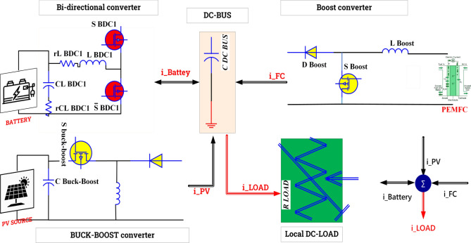
The proposed system is represented in Fig. 1 and divided into four parts as follows:
The photovoltaic system is comprised of photovoltaic panels and a DC/DC converter that is regulated by a fuzzy logic maximum power point tracking (MPPT) algorithm.
PEMFC is connected to a DC/DC boost converter.
Batteries are linked together through the utilization of a DC/DC bidirectional converter.
A DC load.
Figure 1.
Global system configurations.
Photovoltaic modeling
Photovoltaic (PV) generation is a sustainable energy production method that utilizes photovoltaic cells to convert sunlight into electrical energy through the photovoltaic effect. The P-V and I-V characteristics of the PV array exhibit variability based on external conditions, and a DC/DC converter is employed to connect the PV array to the DC bus for maximum power point tracking (MPPT)67. Various MPPT controllers have been proposed by researchers. In reference68, the authors proposed a hardware implementation of fuzzy logic control (FLC) through state machine control (SMC) to enhance power output from the photovoltaic array. It is crucial to extract the maximum available power from the photovoltaic array to optimize its performance. In Ref.69, a novel fuzzy regression maximum power point tracking (MPPT) method was proposed, and in Ref.70, the authors introduced a modified incremental conductance (INC) algorithm for MPPT. Various mathematical models have been developed to illustrate the non-linear behavior of solar panels due to the semiconductor junctions in their design. The PV module is constructed by connecting a series of individual cells in parallel, and the same assembly process is used to create a PV generator or array. The current produced by a single cell can be derived from the electrical circuit illustrated in Fig. 2:
| 1 |
Figure 2.
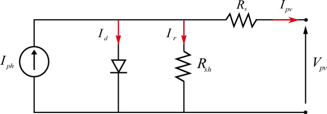
Equivalent model for solar cell.
From Eq. (1), to make up a PV module, we must connect many PV cells in series (Ns) and parallel (Np); the PV module equation is represented in the equation below:
| 2 |
The establishment of a connection that links the photovoltaic array and the DC bus is achieved through the utilization of a buck-boost converter, enabling optimal performance; it is imperative for the system to function at its highest energy capacity. The most prevalent type of DC/DC converter is the buck-boost converter, which merges the electrical characteristics of both a buck converter and a boost converter56.
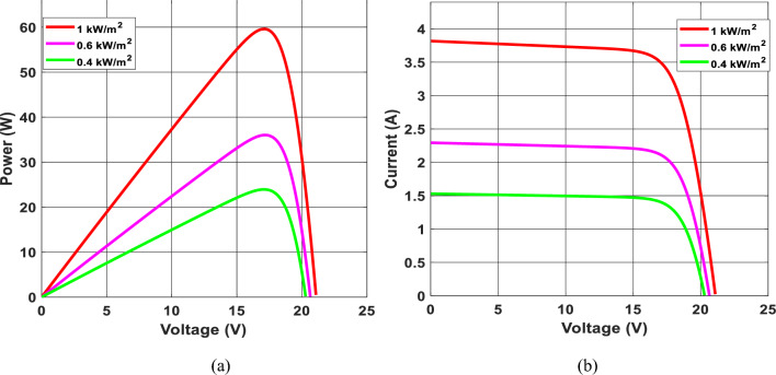
Figure 3 depicts a photovoltaic module’s P-V and I-V characteristics under different sun irradiance conditions. As shown in Fig. 3a, as the outcome voltage Vpv increases, When the voltage hits a particular threshold, the photovoltaic module’s current changes slightly and soon drops while the output voltage continues to rise71,72. As a result, near the highest power limit, the U-I characteristic shapes are non-linear. If the photovoltaic module voltage Vpv remains fixed, the current of the photovoltaic panel Ipv rises proportionately to the increased irradiation. Once the sunlight is constant, PV module power exhibits a non-monotonic tendency with the shift of its Vpv, as shown in Fig. 3b. Once the PV voltage is insufficient, the power of the photovoltaic panel’s Ppv rises as the output voltage Upv improves73. When the photovoltaic module’s Vpv increases, the photovoltaic module’s power Ppv decreases. The P-V characteristic graphs show a significant link between photovoltaic array production power and sunlight. More excellent power adjustment results from a reduced voltage disturbance around the maximum power point.
Figure 3.
P–V and I–V curves of photovoltaic panel.
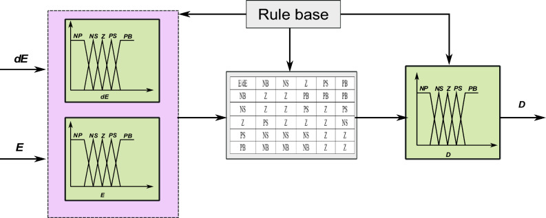
The use of PWM simplifies the control of the buck-boost converter. The framework for maximal PowerPoint tracking incorporates the use of fuzzy logic control. Figure 4 illustrates the graphical depiction of the membership functions pertaining to the input variables and the output variable. As shown in Eq. (3), the fuzzy logic controller (FLC) has two inputs and one output: E, DE, and D:
| 3 |
Figure 4.
Fuzzy logic membership: E, DE, and D.
PEM fuel cell modeling
When compared to other kinds of FCs, the primary benefits of a PEMFC as a power source are adequate electrical power in a steady state, dependable power production, small size, minimal working noise, and eco friendliness74. PEMFC is made up of several fuel cells linked in series called stacks; additionally, the PEMFC curve is non-linear and is influenced by temperature, oxygen and hydrogen pressure, and so on. Figure 5 depicts the electrical model of the PEMFC; the voltage of the stack is determined as follows:
| 4 |
where N represents the total number of PEMFCs associated with the series, and V represents the output voltage.
Figure 5.
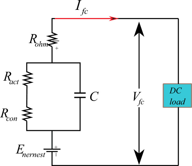
Electrical model of PEM fuel cell.
In general, the output voltage of the fuel cell is represented as follows75:
| 5 |
The output voltage of the fuel cell mentioned above consists of Enersent, Vact, Vconv, and Vohmic.
| 6 |
| 7 |
| 8 |
| 9 |
Enersent denotes the chemical reactions of output voltage, Tfc the temperature, and the PO2 and PH2 the oxygen and hydrogen levels, respectively. Vact represents the activation loss that consists of empirical coefficients and Co2 empirical coefficients. Vohm represents the ohmic voltage that consists of RM, and Rc indicates electron flow resistance and proton resistance, respectively. Vcon donates the concentration overvoltage that consists j, jmax, and b, representing the maximal current, maximum current density, and concentration loss76,77.
Figure 6 below illustrates the properties of a PEMFC stack, specifically its P-V (pressure–voltage) and I-V (current–voltage) characteristics.
Figure 6.
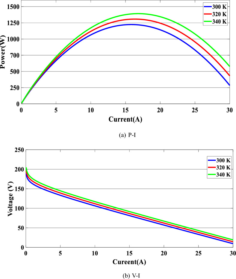
PEMFC characteristic.
P-I and V-I characteristic graphs of the PEMFC stack at various temperatures are shown. As illustrated in Fig. 6a, the increase in voltage and power of the fuel cell when we change the temperature from 300 to 340 K is extremely small. The voltage steadily decreases as the fuel cell current rises, as shown in Fig. 6b.
Battery storage system
Because of the irregular, random, and unpredictability of renewable energy systems (RES) in loads, implementing a BES is critical to supporting energy output and dealing with RES breakdowns78,79. This study applies lithium ion battery technology to a collection of DC-load units. Lead-acid (LA) batteries are an established technology that is suited for static uses and has a cheap initial expenditure cost. Lithium batteries, on the other hand, have better energy and power densities, greater performance, an extended life span, and other technical advantages over competing kinds80,81. As a result of their outstanding performance, these types of batteries are also well-suited for fixed solar systems and the provision of uninterrupted electrical power82,83. To choose the best battery type, a number of technological factors are taken into account, including maturity, weight, size, discharge rate, temperature sensitivity, upkeep, and the effectiveness of costs84,85. In this paper, we use the lithium-ion battery for the advantages mentioned above and summarized in Table 1 below, and the supplementary appendix shows the statistics for the Li-ion battery, the DC/DC boost converter, and the buck converter’s specifications.
Table 1.
Comparison between lithium-ion and lead acid70.
| Lithium-ion | Lead acid |
|---|---|
| Efficiency (%) | |
| 85–95% | 60–80% |
| Advantages | |
| Low upkeep, high effectiveness, lightweight, and low self-discharge | Low capital cost, grown technology |
| Drawbacks | |
| More susceptible to high temps, and is still regarded as a developing technology | The maintenance includes watering, and watching the 50% flow limit—inadequate effectiveness |
Power converter
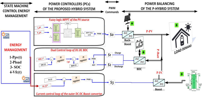
The primary objective of this research is to examine non-isolated DC-DC converters that establish a connection between PV, PEMFC, and battery systems and the load through a DC-coupled bus, as depicted in Fig. 7. The buck-boost converter is a unidirectional apparatus that ensures the flow of Ipv for the purpose of either charging the battery or distributing the load through the local DC bus86. The boost converter provides the provision of the proton exchange membrane fuel cell (PEMFC) current to the load through the direct current (DC) bus. Additionally, it has the capability to charge the battery if necessary. The bi-directional converter (BDC) ensures the bidirectional transfer of electrical current between the battery and the load through the direct current (DC) bus82,87. Figure 7 illustrates the power control scheme of the hybrid system under consideration. The DC-link voltage reference, the reference current for the PEM Fuel Cell (PEMFC), and the reference current for the battery are denoted as V*DC, I*fc, and I*batt, respectively. The photovoltaic (PV) power is monitored and regulated using a buck-boost converter while being controlled by a fuzzy logic maximum power point tracking (MPPT) algorithm under varying environmental conditions88,89. The BDC employs a dual-loop configuration to effectively identify the DC-link voltage and subsequently regulate it in order to compensate for any power imbalances through the utilization of battery storage charge and discharge mechanisms90,91. The calculation of load power is determined by the equation provided below:
| 10 |
Figure 7.
State machine energy management, power controller, and power balancing of the proposed system.
It has been proposed that the DC link is a capacitor. Once all of the basic models were defined, we coupled the power sources according to the DC bus design. Direct current (DC) is provided by every supply source gathered on the bus. The calculation for the DC link current is as follows:
| 11 |
The efficiency of the global system (converters and the load) is represented by η and could be expressed in the equation below:
| 12 |
| 13 |
Suggested state machine energy management strategy
This section centers on the formulation of a power control strategy for an integrated system. An innovative home energy management system (HEMS) has been devised to monitor and regulate the efficiency of the proposed system. The operational strategy designed for this system must account for fluctuations in solar irradiation. The calculation of the net power for the proposed hybrid system can be formulated as follows:
| 14 |
One of the control strategies that is based on rules for microgrids is the state machine control strategy for this proposed hybrid system. As shown in Table 2, the state machine control method used comprises 15 states under three SOC intervals. The three different SoC intervals are classified as high means that (SOC > SOCmax), Normal means that (SOCmax > SOC < SOCmin); and Low means that (SOC < SOCmin). The highest limit SOCmax and lower limit SOCmin of the SOC. It is clear that the batteries' SOC interval, besides the Net power of the system Pnet used to calculate the PEMFC reference power and concurrently taken into consideration, are the following limits: Ppv is the output power of the PV generation device, and Pload is the load requirement; PEMFC system’s minimal, optimal medium and maximum output powers are designated as Pfcmin, Pfcopt, Pmid, and Pfcmax respectively, the SOCmax and SOCmin represent the minimal and the maximal limits respectively.
Table 2.
Proposed state machine control.
| State | SOC | pnet (t) | P*fc (t) |
|---|---|---|---|
| 1 | Low | pnet (t) < Pfcmin | P*fc = Pfcopt |
| 2 | pnet (t) [Pfcmin,Pfcopt[ | P*fc = Pfcopt + Pfcmin | |
| 3 | pnet (t) [Pfccop,Pfmid[ | P*fc = Pmid | |
| 4 | pnet (t) [Pfcmid,Pfcmax[ | P*fc = Pfcmid + Pfcopt | |
| 5 | pnet (t) ≥ Pfcmax | P*fc = Pfcmax | |
| 6 | Medium | pnet (t) < Pfcmin | P*fc = Pfcmin |
| 7 | pnet (t) [Pfcmin,Pfcopt[ | P*fc = Pfcmin + Pfcopt | |
| 8 | pnet (t) [Pfccop,Pfmid[ | P*fc = Pfcopt | |
| 9 | pnet (t) [Pfcmid,Pfcmax[ | P*fc = Pnet | |
| 10 | pnet (t) ≥ Pfcmax | P*fc = Pfcmid + Pfcmin | |
| 11 | Hight | pnet (t) < Pfcmin | P*fc = Pfcmin |
| 12 | pnet (t) [Pfcmin,Pfcopt[ | P*fc = Pfcmid − Pfcopt | |
| 13 | pnet (t) [Pfccop,Pfmid[ | P*fc = Pfcopt | |
| 14 | pnet (t) [Pfcmid,Pfcmax[ | P*fc = Pfcmid − Pfcmin | |
| 15 | pnet (t) ≥ Pfcmax | P*fc = Pfcmid |
Results and discussions
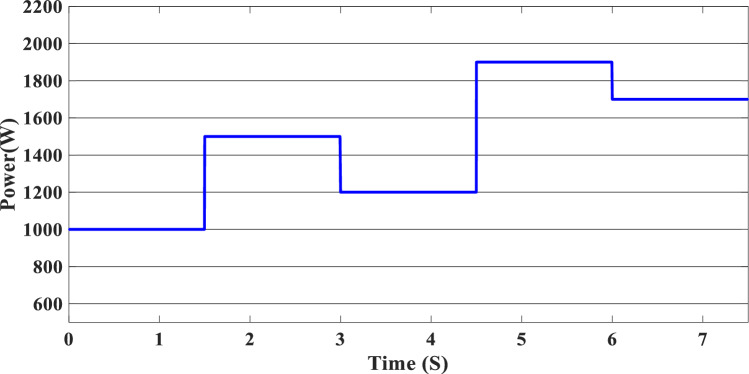
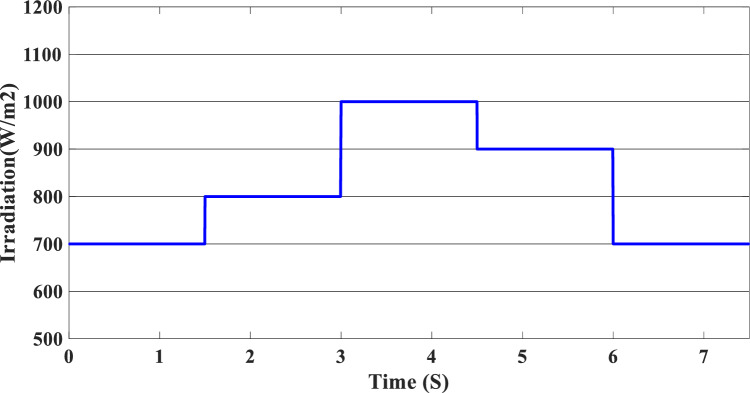
The study of the suggested state machine control for the proposed hybrid system is shown in the section that follows using the MATLAB/Simulink (version: 2016, link: https://in.mathworks.com/products/simulink.html) toolbox. The supplementary appendix displays the global hybrid system’s parameters. The findings of the scenario study emphasize the impact of using variable irradiation for the PV source and the system’s capacity to function effectively under high loads, which is significantly influenced by the different SOC levels. The findings are presented sequentially: PV-PEMFC-battery powers and Load power waveforms, DC bus voltages, and SOCs of the battery, and finally efficiency of the global system in different cases. In this case, the temperature stays at 25 ℃ while the irradiation ranges from 700 to 1000 watts per square meter; we divide this scenario into three cases relying on the SOC first case SOC > SOCmin (low), second case SCOmin < SOC < SOCmax (medium) and third case SOC > SOCmax (hight) and the load-interval of the load = [1000 W–1900 W]. The load demand profile is shown in Fig. (8), the maximum power demand is equal to1900 W, and the minimum value is equal to 1000 W and is divided into time intervals as following:1000 W ∈ [0 s–1.5 s] 1500 W ∈ [1.5 s–3 s], 1200 W ∈ [3 s–4.5 s], 1900 W ∈ [4.5 s–6 s] and 1700 W ∈ [6 s–7.5 s] illustrated in Fig. 8. As represented in Fig. 9, the irradiation profile is divided in the interval time as follows: 700 W ∈ [0 s–1.5 s] 800 W ∈ [1.5 s–3 s], 1000 W ∈ [3 s–4.5 s], 900 W ∈ [4.5 s–6 s] and 700 W ∈ [6 s–7.5 s].
Figure 8.
Load demand profile.
Figure 9.
Irradiation profile.
Case 1: SOC < SOCmin
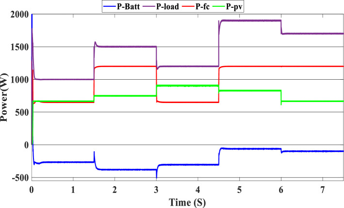
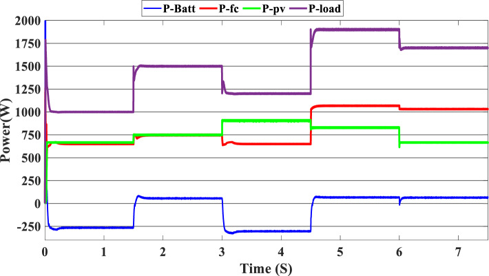
Figure 10 illustrates the variations in power forms for the PV, PEMFC, and batteries, as well as the fluctuations in power demand for the hybrid generating system. The solar system’s maximum power output is 903 W, while the PEMFC’s maximum output is 1350 kW.
Figure 10.
Power generated by the hybrid system (SOC < SOCmin).
At the time interval [0 s–1.5 s], the PV irradiation is equal to 800 W/m2, and the maximum power is equal to 670 W, which is less than the load demand, at the same time to reaches 1000 W which is the load demand, the PEMFC system generated 646 W in order to fulfill the required load demand power and charge the batteries at the same time because the SOC of the batteries is lower than the SOCmin which is equal to 20%. Then, the time interval is equal to [1.5 s–3 s], and the load demand is equal to 1500 W. To reach this value, the irradiation of the PV system is equal to 800 W/m2 and generates power equal to 743 W; the current value is inadequate to fulfill the required load; in this case, the PEMFCs generate power equal to 1.197 kW in order to fulfill the requirements of the load and facilitating the battery charging procedure.
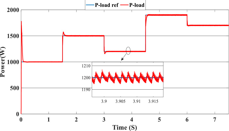
The PV system produces 903 W at 1000 W/m2 from 3 to 4.5 s, requiring power higher than the PV power and equal to 1200 W. In this case, the PEMFC generated a power = 646 W. This power can fulfill the necessary power of load and the surplus power to be utilized for charging the batteries. At 4.5 s, the demand power is high and equal to 1900 W, which is higher than the PV system power, equals 832 W, which means we need more power, so the requirement for power is derived from the PEMFC system, which is equal to 832 W, and the excess power goes to the batteries directly to charge them. Finally, in the time interval [6 s–7.5 s], the load demand is 1700 W, which is greater than the maximum power of the PV system, which means that the PEMFC generates power equal to 1.197 kW to meet needed power needed in the load and charges the batteries. Figure 11 represents the reference load and the load power generated by the hybrid system. It can be seen that the generated power follows the reference load; this implies the effectiveness of the suggested SMC.
Figure 11.
Load power generated from the hybrid system (SOC < SOCmin).
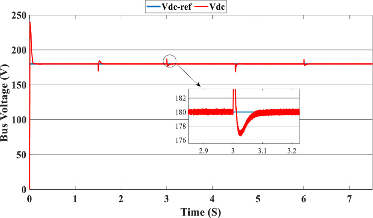
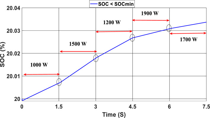
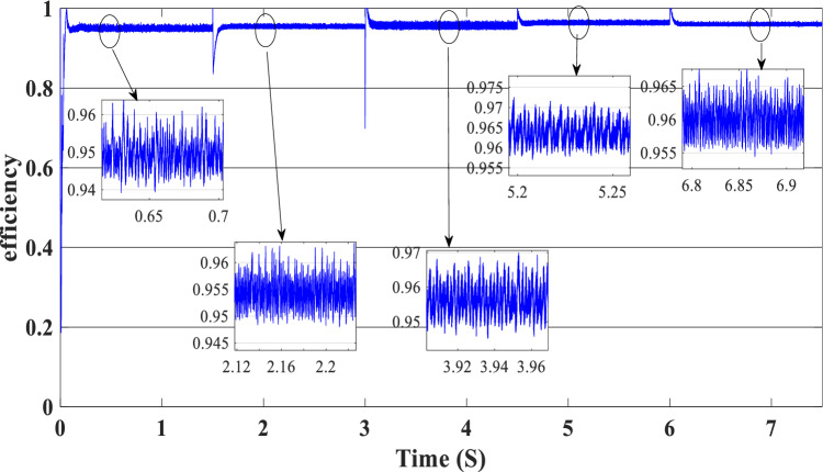
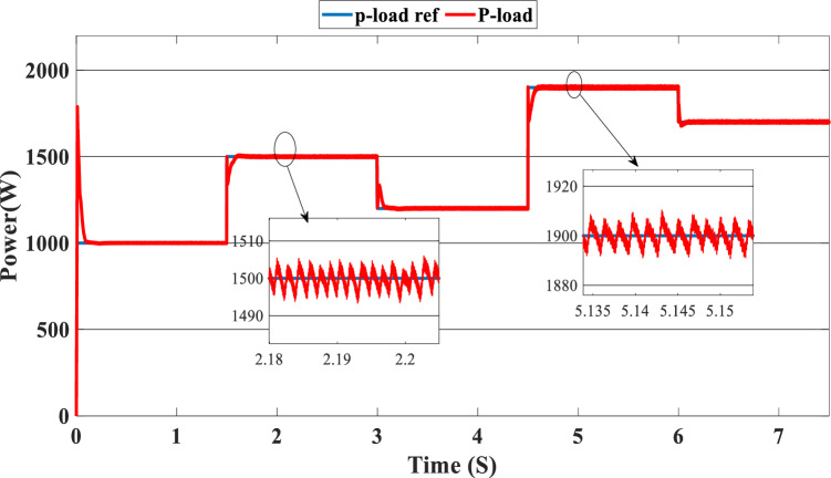
Figure 12 illustrates the DC link voltage, the reference value equal to 180 W. We noticed that the bus voltage tracks the reference efficiently; the picks in the 1.5 s, 3 s, 4.5 s, and 6 s are caused by the change in the load demand. We see there is a deviation from the reference and return rapidly to track the reference value. Figure 13 represents the SOC of the batteries; we notice that the batteries, in this case, are charging no matter what the value of the load demand; the power generated from the PEMFC system supplies the power to the load and charges the battery because the SOC of the batteries is less than the SOCmin. Figure 14 depicts the calculated efficiency of the globe hybrid (buck-boost converter, boost converter, and bi-directional DC/DC converter) during the change in irradiation. This is the case when the SOC is lower than the SOCmin. Moreover, the efficiency of the hybrid system is summarized in Table 3 below.
Figure 12.
DC bus voltage (SOC < SOCmin).
Figure 13.
State of the batteries (SOC < SOCmin).
Figure 14.
Efficiency of the global hybrid system (SOC < SOCmin).
Table 3.
Efficiency of the global system (SOC < SOCmin).
| Time | Load demand (W) | Efficiency (%) |
|---|---|---|
| [0 s–1.5 s] | 1000 | 95 |
| [1.5 s–3 s] | 1500 | 96 |
| [3 s–4.5 s] | 1200 | 95.5 |
| [4.5 s–6 s] | 1900 | 96 |
| [6 s–7.5 s] | 1700 | 96 |
Case 2: SOCmin < SOC < SOCmax
In this case, we suppose the SOC = 65%, which means it’s between SOCmax and SOCmin. As shown in Fig. 9, the PV irradiance profile starts from 700 to 1000 W/m2 with a sudden change in 1.5 s, 3 s, 4.5 s, and 6 s, respectively. The variation in load power demand mentioned in Fig. 15 shows the power produced by the PV system, PEMFC system, and storage. Additionally, when the demand is 1000 W, and the PV system is producing 670 W, this indicates that we need more power to carry out the load because this number is less than the load requirement. In this instance, the PEMFC system produces a power of 646 W, which is more than enough to carry out the load and fully charge the batteries. In the following time interval [1.5 s–3 s], the PV’s irradiation changes from 700 to 800 W/m2, the PV system produces more power equal to 754 W, and at the same time, the load demand increases to 1500 W, the current level of supply is inadequate to satisfy the existing demand. In this case, the PEMFC and the batteries generate power 740 W from the PEMFC and 62 W from the batteries). At 3 s, the power of the load decreased to 1200 W, and the PV generates power equal to 912 W/m2 while the irradiation is equal to 1000 W; we need more energy to meet the load power, in this case, the PEMFC power is equal to 646 W and it’s enough and the exceed power go to charge the batteries. The load demand increased to 1900 W during the following time frame [4.5 s–6 s], which indicates that neither the PV nor the PEMFC could meet the load’s requirements. In the present scenario, the batteries generated sufficient power to fulfill the load's energy requirements.
Figure 15.
Power generated by the hybrid system (SOCmin < SOC < SOCmax).
The precise duration range is [6 s–7.5 s]. The PV system cannot satisfy the requirements when the load is reduced to 1700 W, and the sunlight is equivalent to 700 W/m2, so the PEMFC and batteries generate the necessary power, as shown in Fig. 15.
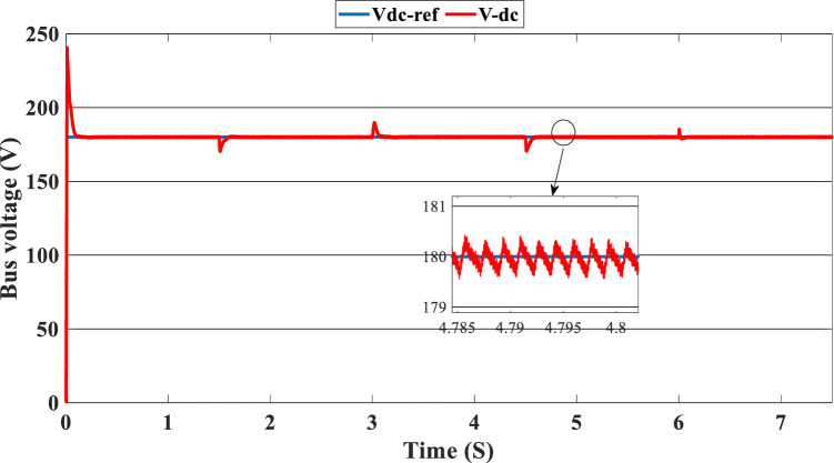
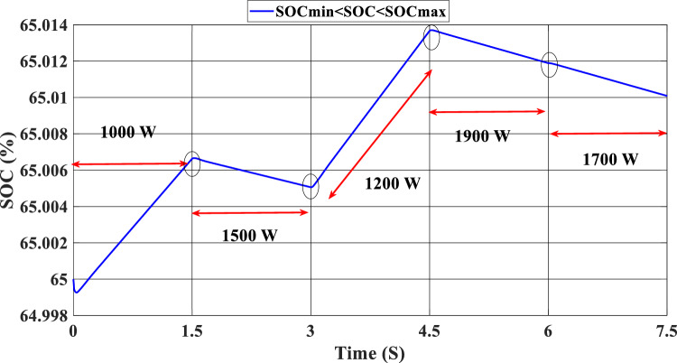
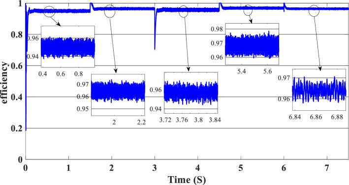
Figure 16 illustrates the required load. As can be seen, the total power generated by the PV, PEMFC, and batteries tracks the reference load power, indicating that the suggested SMC operates effectively. Figure 17 shows the DC-link voltage; as we can see, it follows the 180 V reference voltage. However, we also observed that the bus voltage deviates from the reference when the load demand changes and we quickly return to tracking the reference voltage with a short response time. Figure 18 represents the SOC of the batteries in intervals of time [0 s–1.5 s]. The batteries charge because there is an exceeded power from the (PV and PEMFC), next from 1.5 to 3 s, the batteries discharge because the PV+PEMFC can't satisfy the load demand, so the battery gives a power, [3 s–4.5 s] the batteries charge finally in the interval time [4.5 s–7.5 s]. The batteries discharge no matter the load power value because we need the power to fulfill the needs of the load. Figure 19 represents the efficiency of the suggested system; in this case, the SOC belongs to the interval SOCmin and SOCmax; from the figure, we can notice that the lowest efficiency is 95%, and the maximum efficiency is 97%, the Table 4 below summarized the results founds.
Figure 16.
Load demand power (SOCmin < SOC < SOCmax).
Figure 17.
DC-bus voltage (SOCmin < SOC < SOCmax).
Figure 18.
State of the batteries (SOCmin < SOC < SOCmax).
Figure 19.
Efficiency of the hybrid system (SOCmin < SOC < SOCmax).
Table 4.
Efficiency of the global system (SOCmax < SOC < SOCmax).
| Time | Load demand (W) | Efficiency (%) |
|---|---|---|
| [0 s–1.5 s] | 1000 | 95 |
| [1.5 s–3 s] | 1500 | 95.5 |
| [3 s–4.5 s] | 1200 | 95.5 |
| [4.5 s–6 s] | 1900 | 97 |
| [6 s–7.5 s] | 1700 | 96.5 |
Case 3: SOC > SOCmax
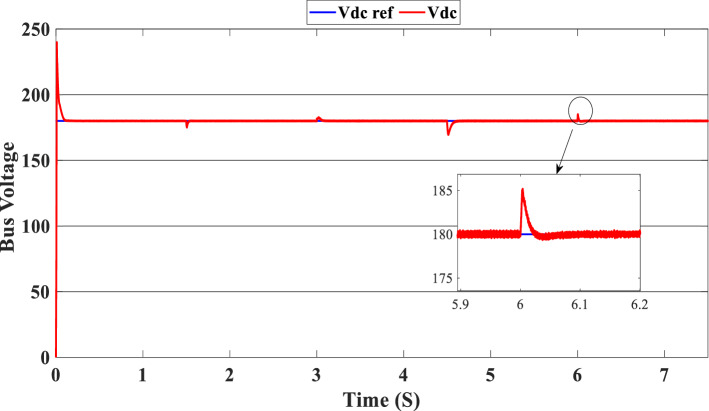
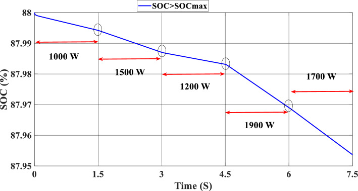
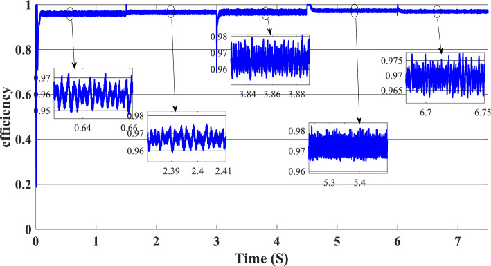
In this case, the state of the charger is higher than SOCmax, which is equal to 88%, to test the objective of the global proposed system like the previous cases at the same irradiation profile and the load demand. Figure 20 illustrates the power output derived from the renewable hybrid source alongside the consumption of the load. The power in the load is always higher than the primary source (PV); in the first interval [0 s–1.5 s], the PV system generates power not enough to fulfill the load demand; in this case, the batteries generate power to meet the needs, and the PEMFC also generates a minimum power to support the batteries. From 1.5 s, the irradiation change to 800W/m2 the power generated from (PV) is less than the required load this case, like the previous one, the batteries still discharge, and the PEMFC supports the needs of the power needs when the (PV+Batteries) cant meets the need of the Load, now comes the interval time [3 s–4.5 s] in this time the load demand 1200 W which means the PV+batteris+PEMFC must generate power to fulfill the load and that is what we can see from the figure, that the batteries +PV generate a power to fulfill the load and the PEMFC work in a lower value to support the needs. When the irradiation is equal to 900 W/m2, in the time interval [4.5 s–6 s], the PV produces power, and the batteries also discharge, and the need for the power to fulfill the load is compensated by the PEMFC. Finally, when the interval time [6 s–7.5 s], the power from the primary source (PV) produces low power in the previous state the batteries are still discharging, and the PEMFC gives the exact value of the power to complete The photovoltaic system (PV), in conjunction with batteries, fulfill the load demand, which is equivalent to 1700 W. Figure 21 represents the load demand. We can see that the load follows the reference load with a small time response when we change the load value. Figure 22 depicts the DC link voltage. DC bus voltage follows the standard 180 V, with deviations occurring every 1.5 s, 3 s, 4.5 s, and 6 s. Figure 23 represents the SOC of the batteries with the initial value equal to 88% > SOCmax. In this case, the batteries must discharge whatever the value of the load and the primary source is. Figure 24 summarizes the global system’s effectiveness for different load demand values in Table 5 below.
Figure 20.
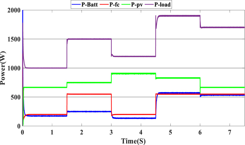
Power generated by the hybrid system ( SOC > SOCmax).
Figure 21.
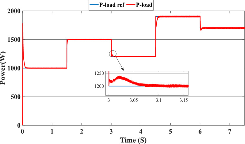
Load demand (SOC > SOCmax).
Figure 22.
DC link voltage (SOC > SOCmax).
Figure 23.
State of the batteries (SOC > SOCmax).
Figure 24.
Efficiency of the hybrid system (SOC > SOCmax).
Table 5.
Efficiency of the global system (SOC > SOCmax).
| Time | Load demand (W) | Efficiency (%) |
|---|---|---|
| [0 s–1.5 s] | 1000 | 96 |
| [1.5 s–3 s] | 1500 | 96.5 |
| [3 s–4.5 s] | 1200 | 96.5 |
| [4.5 s–6 s] | 1900 | 97.5 |
| [6 s–7.5 s] | 1700 | 97 |
Conclusion and future research directions
This study introduced a new state machine control (SMC) for a multi-source renewable system (MSRS) that includes photovoltaic (PV), proton exchange membrane fuel cell (PEMFC), and batteries. The proposed control method was assessed using MATLAB/Simulink (version: 2016, link: https://in.mathworks.com/products/simulink.html) simulations. The SMC strategy was devised to efficiently oversee the energy resources in the MSRS, taking into account fluctuating solar irradiation levels and battery state of charge (SOC). The simulation results showcased the resilience and efficacy of the suggested SMC in regulating the MSRS across different operational circumstances. The MSRS was determined to effectively fulfill the load requirement while simultaneously ensuring stability and achieving satisfactory performance. The system closely monitored and controlled key parameters such as DC bus voltage, battery state of charge (SOC), and overall system efficiency, ensuring they remained within specified limits. In summary, this research contributes to the advancement of efficient energy management techniques for renewable energy systems, emphasizing the importance of optimal power control strategies in enhancing the overall performance and sustainability of MSRS. However, further experimental validation is required to corroborate the simulation findings and ensure real-world applicability. Additionally, future research could explore integrating the MSRS with grid systems to enable the bi-directional flow of excess electricity, further enhancing the system's flexibility and reliability in meeting dynamic energy demands. This study paves the way for the development and deployment of innovative energy management strategies for a more sustainable and environmentally friendly future.
Future research endeavors in this domain may focus on addressing the reliability and robustness of the state machine control (SMC) strategy under varying conditions, notably through real-world testing to verify the performance of the multi-source renewable system (MSRS). Further exploration could also involve the integration of the MSRS with the grid to enable energy exchange and optimize renewable resource utilization, while potential synergies and trade-offs between different energy sources, such as wind, hydropower, and solar, could be studied for the development of more efficient and reliable hybrid energy systems. There’s also a strong potential in developing more advanced energy management algorithms, such as machine learning-based approaches, to enhance the system’s adaptability and efficiency. Furthermore, an environmental impact assessment could be performed to compare the system’s sustainability and carbon footprint to traditional energy systems, while a full economic study can determine the system’s cost-effectiveness and return on investment. Furthermore, the creation of supportive legislative frameworks and regulatory standards may pave the road for widespread implementation. Finally, by studying these pathways, future research can considerably develop multi-source renewable systems while also promoting sustainable and resilient energy solutions. PEMFC is a reliable and durable backup power supply in the given scenario. It also charges the batteries and acts as the third backup option when the energy sources fail to satisfy the load requirements. To optimize future operations, it is recommended to construct a direct link between this system and the network to streamline the process of injecting surplus power. We will also add electrolysis to complete the global system.
Supplementary Information
Author contributions
Badreddine Kanouni, Abd Essalam Badoud: conceptualization, methodology, software, visualization, investigation, writing—original draft preparation. Saad Mekhilef: data curation, validation, supervision, resources, writing—review & editing. Mohit Bajaj, Ievgen Zaitsev: project administration, supervision, resources, writing—review & editing.
Data availability
The datasets used and/or analysed during the current study available from the corresponding author on reasonable request.
Competing interests
The authors declare no competing interests.
Footnotes
Publisher's note
Springer Nature remains neutral with regard to jurisdictional claims in published maps and institutional affiliations.
Contributor Information
Abd Essalam Badoud, Email: badoudabde@univ-setif.dz.
Mohit Bajaj, Email: thebestbajaj@gmail.com.
Ievgen Zaitsev, Email: zaitsev@i.ua.
Supplementary Information
The online version contains supplementary material available at 10.1038/s41598-024-58785-2.
References
- 1.Panda S, Mohanty S, Rout PK, Sahu BK, Bajaj M, Zawbaa HM, et al. Residential demand side management model, optimization and future perspective: A review. Energy Rep. 2022;8:3727–3766. doi: 10.1016/j.egyr.2022.02.300. [DOI] [Google Scholar]
- 2.Dashtdar M, Bajaj M, Hosseinimoghadam SMS. Design of optimal energy management system in a residential microgrid based on smart control. Smart Sci. 2022;10:25–39. doi: 10.1080/23080477.2021.1949882. [DOI] [Google Scholar]
- 3.Wu D, Nariman GS, Mohammed SQ, Shao Z, Rezvani A, Mohajeryami S. Modeling and simulation of novel dynamic control strategy for PV–wind hybrid power system using FGS−PID and RBFNSM methods. Soft Comput. 2020;24:8403–8425. doi: 10.1007/s00500-019-04408-2. [DOI] [Google Scholar]
- 4.Deghfel N, Badoud AE, Merahi F, Bajaj M, Zaitsev I. A new intelligently optimized model reference adaptive controller using GA and WOA-based MPPT techniques for photovoltaic systems. Sci. Rep. 2024;14:6827. doi: 10.1038/s41598-024-57610-0. [DOI] [PMC free article] [PubMed] [Google Scholar]
- 5.Merahi F, Badoud AE, Mekhilef S. A novel power management strategies in PV-wind-based grid connected hybrid renewable energy system using proportional distribution algorithm. Int. Trans. Electr. Energy Syst. 2021 doi: 10.1002/2050-7038.12931. [DOI] [Google Scholar]
- 6.Ma Z, Zhao J, Yu L, Yan M, Liang L, Wu X, et al. A review of energy supply for biomachine hybrid robots. Cyborg Bionic Syst. 2023 doi: 10.34133/cbsystems.0053. [DOI] [PMC free article] [PubMed] [Google Scholar]
- 7.Jiang H, Xiao Z, Li Z, Xu J, Zeng F, Wang D. An energy-efficient framework for internet of things underlaying heterogeneous small cell networks. IEEE Trans. Mob. Comput. 2022;21:31–43. doi: 10.1109/TMC.2020.3005908. [DOI] [Google Scholar]
- 8.Luca R, Whiteley M, Neville T, Shearing PR, Brett DJL. Comparative study of energy management systems for a hybrid fuel cell electric vehicle—A novel mutative fuzzy logic controller to prolong fuel cell lifetime. Int. J. Hydrog. Energy. 2022;47:24042–24058. doi: 10.1016/j.ijhydene.2022.05.192. [DOI] [Google Scholar]
- 9.Fang Z, Wang J, Liang J, Yan Y, Pi D, Zhang H, et al. Authority allocation strategy for shared steering control considering human-machine mutual trust level. IEEE Trans. Intell. Veh. 2024;9:2002–2015. doi: 10.1109/TIV.2023.3300152. [DOI] [Google Scholar]
- 10.Liang J, Feng J, Fang Z, Lu Y, Yin G, Mao X, et al. An energy-oriented torque-vector control framework for distributed drive electric vehicles. IEEE Trans. Transp. Electrif. 2023;9:4014–4031. doi: 10.1109/TTE.2022.3231933. [DOI] [Google Scholar]
- 11.Abdelkareem MA, El Haj AM, Sayed ET, Soudan B. Recent progress in the use of renewable energy sources to power water desalination plants. Desalination. 2018;435:97–113. doi: 10.1016/j.desal.2017.11.018. [DOI] [Google Scholar]
- 12.Mfetoum IM, Ngoh SK, Molu RJJ, Nde Kenfack BF, Onguene R, Naoussi SRD, et al. A multilayer perceptron neural network approach for optimizing solar irradiance forecasting in Central Africa with meteorological insights. Sci. Rep. 2024;14:3572. doi: 10.1038/s41598-024-54181-y. [DOI] [PMC free article] [PubMed] [Google Scholar]
- 13.Kong L, Yu J, Cai G. Modeling, control and simulation of a photovoltaic /hydrogen/ supercapacitor hybrid power generation system for grid-connected applications. Int. J. Hydrog. Energy. 2019;44:25129–25144. doi: 10.1016/j.ijhydene.2019.05.097. [DOI] [Google Scholar]
- 14.Mohammadi A, Mehrpooya M. A comprehensive review on coupling different types of electrolyzer to renewable energy sources. Energy. 2018;158:632–655. doi: 10.1016/j.energy.2018.06.073. [DOI] [Google Scholar]
- 15.Lyu W, Hu Y, Liu J, Chen K, Liu P, Deng J, et al. Impact of battery electric vehicle usage on air quality in three Chinese first-tier cities. Sci. Rep. 2024;14:21. doi: 10.1038/s41598-023-50745-6. [DOI] [PMC free article] [PubMed] [Google Scholar]
- 16.Ma X, Wan Y, Wang Y, Dong X, Shi S, Liang J, et al. Multi-parameter practical stability region analysis of wind power system based on limit cycle amplitude tracing. IEEE Trans. Energy Convers. 2023;38:2571–2583. doi: 10.1109/TEC.2023.3274775. [DOI] [Google Scholar]
- 17.Yang C, Kumar Nutakki TU, Alghassab MA, Alkhalaf S, Alturise F, Alharbi FS, et al. Optimized integration of solar energy and liquefied natural gas regasification for sustainable urban development: Dynamic modeling, data-driven optimization, and case study. J. Clean Prod. 2024;447:141405. doi: 10.1016/j.jclepro.2024.141405. [DOI] [Google Scholar]
- 18.He T, Zheng Y, Liang X, Li J, Lin L, Zhao W, et al. A highly energy-efficient body-coupled transceiver employing a power-on-demand amplifier. Cyborg Bionic Syst. 2023 doi: 10.34133/cbsystems.0030. [DOI] [PMC free article] [PubMed] [Google Scholar]
- 19.Fan J, Zhou X. Optimization of a hybrid solar/wind/storage system with bio-generator for a household by emerging metaheuristic optimization algorithm. J. Energy Storage. 2023;73:108967. doi: 10.1016/j.est.2023.108967. [DOI] [Google Scholar]
- 20.Yang Y, Si Z, Jia L, Wang P, Huang L, Zhang Y, et al. Whether rural rooftop photovoltaics can effectively fight the power consumption conflicts at the regional scale—A case study of Jiangsu province. Energy Build. 2024 doi: 10.1016/j.enbuild.2024.113921. [DOI] [Google Scholar]
- 21.Kouro S, Leon JI, Vinnikov D, Franquelo LG. Grid-connected photovoltaic systems: An overview of recent research and emerging PV converter technology. IEEE Ind. Electron Mag. 2015;9:47–61. doi: 10.1109/MIE.2014.2376976. [DOI] [Google Scholar]
- 22.Nagarajan K, Rajagopalan A, Bajaj M, Sitharthan R, Dost Mohammadi SA, Blazek V. Optimizing dynamic economic dispatch through an enhanced Cheetah-inspired algorithm for integrated renewable energy and demand-side management. Sci. Rep. 2024;14:3091. doi: 10.1038/s41598-024-53688-8. [DOI] [PMC free article] [PubMed] [Google Scholar]
- 23.Naoussi SRD, Saatong KT, Molu RJJ, Mbasso WF, Bajaj M, Louzazni M, et al. Enhancing MPPT performance for partially shaded photovoltaic arrays through backstepping control with genetic algorithm-optimized gains. Sci. Rep. 2024;14:3334. doi: 10.1038/s41598-024-53721-w. [DOI] [PMC free article] [PubMed] [Google Scholar]
- 24.Begum B, Jena NK, Sahu BK, Ray P, Bajaj M, Singh AR, et al. Application of an intelligent fuzzy logic based sliding mode controller for frequency stability analysis in a deregulated power system using OPAL-RT platform. Energy Rep. 2024;11:510–534. doi: 10.1016/j.egyr.2023.12.023. [DOI] [Google Scholar]
- 25.Panda S, Mohanty S, Rout PK, Sahu BK, Parida SM, Samanta IS, et al. A comprehensive review on demand side management and market design for renewable energy support and integration. Energy Rep. 2023;10:2228–2250. doi: 10.1016/j.egyr.2023.09.049. [DOI] [Google Scholar]
- 26.Basaran K, Cetin NS, Borekci S. Energy management for on-grid and off-grid wind/PV and battery hybrid systems. IET Renew. Power Gener. 2017;11:642–649. doi: 10.1049/iet-rpg.2016.0545. [DOI] [Google Scholar]
- 27.Lu Z, Wang J, Shahidehpour M, Bai L, Xiao Y, Li H. Cooperative operation of distributed energy resources and thermal power plant with a carbon-capture-utilization-and-storage system. IEEE Trans. Power Syst. 2024;39:1850–1866. doi: 10.1109/TPWRS.2023.3253809. [DOI] [Google Scholar]
- 28.Wang Q, Hu J, Wu Y, Zhao Y. Output synchronization of wide-area heterogeneous multi-agent systems over intermittent clustered networks. Inf. Sci. 2023;619:263–275. doi: 10.1016/j.ins.2022.11.035. [DOI] [Google Scholar]
- 29.Duan Y, Zhao Y, Hu J. An initialization-free distributed algorithm for dynamic economic dispatch problems in microgrid: Modeling, optimization and analysis. Sustain. Energy Grids Netw. 2023;34:101004. doi: 10.1016/j.segan.2023.101004. [DOI] [Google Scholar]
- 30.Zhao L, Qu S, Xu H, Wei Z, Zhang C. Energy-efficient trajectory design for secure SWIPT systems assisted by UAV-IRS. Veh. Commun. 2024 doi: 10.1016/j.vehcom.2023.100725. [DOI] [Google Scholar]
- 31.Zhang X, Deng H, Xiong Z, Liu Y, Rao Y, Lyu Y, et al. Secure routing strategy based on attribute-based trust access control in social-aware networks. J. Signal Process. Syst. 2024 doi: 10.1007/s11265-023-01908-1. [DOI] [Google Scholar]
- 32.Baik M, Hammoudi M, Salhi Y, Kirati SK. Hydrogen production by hybrid system and its conversion by fuel cell in Algeria: Djanet. Int. J. Hydrog. Energy. 2018;43:3466–3474. doi: 10.1016/j.ijhydene.2017.11.074. [DOI] [Google Scholar]
- 33.Kumar BA, Jyothi B, Rathore RS, Singh AR, Kumar BH, Bajaj M. A novel framework for enhancing the power quality of electrical vehicle battery charging based on a modified Ferdowsi converter. Energy Rep. 2023;10:2394–2416. doi: 10.1016/j.egyr.2023.09.070. [DOI] [Google Scholar]
- 34.Lyu T, Xu H, Zhang L, Han Z. Source selection and resource allocation in wireless-powered relay networks: An adaptive dynamic programming-based approach. IEEE Internet Things J. 2024;11:8973–8988. doi: 10.1109/JIOT.2023.3321673. [DOI] [Google Scholar]
- 35.Yu F, Lu C, Zhou J, Yin L, Wang K. A knowledge-guided bi-population evolutionary algorithm for energy-efficient scheduling of distributed flexible job shop problem. Eng. Appl. Artif. Intell. 2024;128:107458. doi: 10.1016/j.engappai.2023.107458. [DOI] [Google Scholar]
- 36.Gu Y, Xiang X, Li W, He X. Mode-adaptive decentralized control for renewable DC microgrid with enhanced reliability and flexibility. IEEE Trans. Power Electron. 2014;29:5072–5080. doi: 10.1109/TPEL.2013.2294204. [DOI] [Google Scholar]
- 37.Sechilariu M, Wang BC, Locment F, Jouglet A. DC microgrid power flow optimization by multi-layer supervision control. Design and experimental validation. Energy Convers. Manag. 2015;82:1–10. doi: 10.1016/j.enconman.2014.03.010. [DOI] [Google Scholar]
- 38.Liu J, Luo W, Yang X, Wu L. Robust model-based fault diagnosis for PEM fuel cell air-feed system. IEEE Trans. Ind. Electron. 2016;63:3261–3270. doi: 10.1109/TIE.2016.2535118. [DOI] [Google Scholar]
- 39.Han Y, Chen W, Li Q, Yang H, Zare F, Zheng Y. Two-level energy management strategy for PV-Fuel cell-battery-based DC microgrid. Int. J. Hydrog. Energy. 2019;44:19395–19404. doi: 10.1016/j.ijhydene.2018.04.013. [DOI] [Google Scholar]
- 40.Han Y, Li Q, Wang T, Chen W, Ma L. Multisource coordination energy management strategy based on SOC consensus for a PEMFC–battery–supercapacitor hybrid tramway. IEEE Trans. Veh. Technol. 2018;67:296–305. doi: 10.1109/TVT.2017.2747135. [DOI] [Google Scholar]
- 41.Olatomiwa L, Mekhilef S, Ismail MS, Moghavvemi M. Energy management strategies in hybrid renewable energy systems: A review. Renew. Sustain. Energy Rev. 2016;62:821–835. doi: 10.1016/j.rser.2016.05.040. [DOI] [Google Scholar]
- 42.Sahoo GK, Choudhury S, Rathore RS, Bajaj M, Dutta AK. Scaled conjugate-artificial neural network-based novel framework for enhancing the power quality of grid-tied microgrid systems. Alex. Eng. J. 2023;80:520–541. doi: 10.1016/j.aej.2023.08.081. [DOI] [Google Scholar]
- 43.Sahoo GK, Choudhury S, Rathore RS, Bajaj M. A novel prairie dog-based meta-heuristic optimization algorithm for improved control, better transient response, and power quality enhancement of hybrid microgrids. Sensors. 2023;23:5973. doi: 10.3390/s23135973. [DOI] [PMC free article] [PubMed] [Google Scholar]
- 44.Azaroual M, Hermann DT, Ouassaid M, Bajaj M, Maaroufi M, Alsaif F, et al. Optimal solution of peer-to-peer and peer-to-grid trading strategy sharing between prosumers with grid-connected photovoltaic/wind turbine/battery storage systems. Int. J. Energy Res. 2023;2023:1–17. doi: 10.1155/2023/6747936. [DOI] [Google Scholar]
- 45.Choudhury S, Varghese GT, Mohanty S, Kolluru VR, Bajaj M, Blazek V, et al. Energy management and power quality improvement of microgrid system through modified water wave optimization. Energy Rep. 2023;9:6020–6041. doi: 10.1016/j.egyr.2023.05.068. [DOI] [Google Scholar]
- 46.Zhang Z, Guan C, Liu Z. Real-time optimization energy management strategy for fuel cell hybrid ships considering power sources degradation. IEEE Access. 2020;8:87046–87059. doi: 10.1109/ACCESS.2020.2991519. [DOI] [Google Scholar]
- 47.Qi W, Li Y, Li H, Wayne SW, Lin X. The development and numerical verification of a compromised real time optimal control algorithm for hybrid electric vehicle. J. Power Sources. 2019;443:227272. doi: 10.1016/j.jpowsour.2019.227272. [DOI] [Google Scholar]
- 48.Snoussi J, Ben Elghali S, Benbouzid M, Mimouni M. Auto-adaptive filtering-based energy management strategy for fuel cell hybrid electric vehicles. Energies. 2018;11:2118. doi: 10.3390/en11082118. [DOI] [Google Scholar]
- 49.Zhang C, Shen Y, Wang Y-X. Wavelet transform-based energy management strategy for fuel cell/variable-structure super-capacitor hybrid power system. In: Zhang C, Shen Y, Wang Y-X, editors. 2020 Asia Energy and Electrical Engineering Symposium. IEEE; 2020. pp. 732–736. [Google Scholar]
- 50.Konara KMSY, Kolhe ML, Sharma A. Power dispatching techniques as a finite state machine for a standalone photovoltaic system with a hybrid energy storage. AIMS Energy. 2020;8:214–230. doi: 10.3934/energy.2020.2.214. [DOI] [Google Scholar]
- 51.Corcau JI, Dinca L. Fuzzy energy management scheme for a hybrid power sources of high-altitude pseudosatellite. Model. Simul. Eng. 2020;2020:1–13. doi: 10.1155/2020/5459098. [DOI] [Google Scholar]
- 52.Mohammadzadeh A, Rathinasamy S. Energy management in photovoltaic battery hybrid systems: A novel type-2 fuzzy control. Int. J. Hydrog. Energy. 2020;45:20970–20982. doi: 10.1016/j.ijhydene.2020.05.187. [DOI] [Google Scholar]
- 53.Tifour B, Moussa B, Ahmed H, Camel T. Monitoring and energy management approach for a fuel cell hybrid electric vehicle. Diagnostyka. 2020;21:15–29. doi: 10.29354/diag/123996. [DOI] [Google Scholar]
- 54.Zhang Z, Sato K, Nagasaki Y, Tsuda M, Miyagi D, Komagome T, et al. Continuous operation in an electric and hydrogen hybrid energy storage system for renewable power generation and autonomous emergency power supply. Int. J. Hydrog. Energy. 2019;44:23384–23395. doi: 10.1016/j.ijhydene.2019.07.028. [DOI] [Google Scholar]
- 55.Feng J, Wang W, Zeng H-B. Integral sliding mode control for a class of nonlinear multi-agent systems with multiple time-varying delays. IEEE Access. 2024;12:10512–10520. doi: 10.1109/ACCESS.2024.3354030. [DOI] [Google Scholar]
- 56.Badoud AE, Merahi F, Ould Bouamama B, Mekhilef S. Bond graph modeling, design and experimental validation of a photovoltaic/fuel cell/ electrolyzer/battery hybrid power system. Int. J. Hydrog. Energy. 2021;46:24011–24027. doi: 10.1016/j.ijhydene.2021.05.016. [DOI] [Google Scholar]
- 57.Mahjoub S, Chrifi-Alaoui L, Drid S, Derbel N. Control and implementation of an energy management strategy for a PV–wind–battery microgrid based on an intelligent prediction algorithm of energy production. Energies. 2023;16:1883. doi: 10.3390/en16041883. [DOI] [Google Scholar]
- 58.Kamel AA, Rezk H, Abdelkareem MA. Enhancing the operation of fuel cell-photovoltaic-battery-supercapacitor renewable system through a hybrid energy management strategy. Int. J. Hydrog. Energy. 2021;46:6061–6075. doi: 10.1016/j.ijhydene.2020.06.052. [DOI] [Google Scholar]
- 59.Silva SB, Severino MM, de Oliveira MAG. A stand-alone hybrid photovoltaic, fuel cell and battery system: A case study of Tocantins, Brazil. Renew. Energy. 2013;57:384–389. doi: 10.1016/j.renene.2013.02.004. [DOI] [Google Scholar]
- 60.Behzadi MS, Niasati M. Comparative performance analysis of a hybrid PV/FC/battery stand-alone system using different power management strategies and sizing approaches. Int. J. Hydrog. Energy. 2015;40:538–548. doi: 10.1016/j.ijhydene.2014.10.097. [DOI] [Google Scholar]
- 61.Barhoumi EM, Zghaibeh M, Okonkwo PC, Hasan NU, Farhani S, Bacha F. Energy management system for photovoltaic-battery-fuel cell using arduino board and Matlab Simulink. In: Barhoumi EM, Zghaibeh M, Okonkwo PC, Hasan NU, Farhani S, Bacha F, editors. 2022 IEEE Delhi Section Conference. IEEE; 2022. pp. 1–6. [Google Scholar]
- 62.Mounica V, Obulesu YP. Hybrid power management strategy with fuel cell, battery, and supercapacitor for fuel economy in hybrid electric vehicle application. Energies. 2022;15:4185. doi: 10.3390/en15124185. [DOI] [Google Scholar]
- 63.Pathak PK, Yadav AK. Design of battery charging circuit through intelligent MPPT using SPV system. Sol. Energy. 2019;178:79–89. doi: 10.1016/j.solener.2018.12.018. [DOI] [Google Scholar]
- 64.Pathak PK, Yadav AK, Padmanaban S, Alvi PA. Design of robust multi-rating battery charger for charging station of electric vehicles via solar PV system. Electr. Power Compon. Syst. 2022;50:751–761. doi: 10.1080/15325008.2022.2139870. [DOI] [Google Scholar]
- 65.Pathak PK, Yadav AK, Padmanaban S, Twala B, Kamwa I. Design of smart battery charging circuit via photovoltaic for hybrid electric vehicle. IET Renew. Power Gener. 2023 doi: 10.1049/rpg2.12656. [DOI] [Google Scholar]
- 66.Pathak PK, Yadav AK, Padmanaban S, Alvi PA, Kamwa I. Fuel cell-based topologies and multi-input DC–DC power converters for hybrid electric vehicles: A comprehensive review. IET Gener. Transm. Distrib. 2022;16:2111–2139. doi: 10.1049/gtd2.12439. [DOI] [Google Scholar]
- 67.Yu F, Lu C, Zhou J, Yin L. Mathematical model and knowledge-based iterated greedy algorithm for distributed assembly hybrid flow shop scheduling problem with dual-resource constraints. Expert Syst. Appl. 2024;239:122434. doi: 10.1016/j.eswa.2023.122434. [DOI] [Google Scholar]
- 68.Laib A, Krim F, Talbi B, Feroura HBA. Hardware implementation of fuzzy maximum power point tracking through sliding mode current control for photovoltaic systems. Rev. Roum. Des Sci. Tech. Électrotech. Énerg. 2021;66:91–96. [Google Scholar]
- 69.Bayarassou H, Megri AF. New approach based on a fuzzy regression model for a photovoltaic system. Electr. Power Syst. Res. 2023;217:109091. doi: 10.1016/j.epsr.2022.109091. [DOI] [Google Scholar]
- 70.Rai N, Abbadi A, Hamidia F, Kanouni B, Kahlessenane A. A new modified incremental conductance algorithm used for PV system. In: Hatti M, editor. Artificial Intelligence and Heuristics for Smart Energy Efficiency in Smart Cities: Case Study: Tipasa, Algeria. Springer International Publishing; 2022. pp. 256–265. [Google Scholar]
- 71.Liu F, Li G, Lu C, Yin L, Zhou J. A tri-individual iterated greedy algorithm for the distributed hybrid flow shop with blocking. Expert Syst. Appl. 2024;237:121667. doi: 10.1016/j.eswa.2023.121667. [DOI] [Google Scholar]
- 72.Yin L, Zhuang M, Jia J, Wang H. Energy saving in flow-shop scheduling management: An improved multiobjective model based on grey wolf optimization algorithm. Math. Probl. Eng. 2020;2020:1–14. doi: 10.1155/2020/9462048. [DOI] [Google Scholar]
- 73.Feroldi D, Degliuomini LN, Basualdo M. Energy management of a hybrid system based on wind–solar power sources and bioethanol. Chem. Eng. Res. Des. 2013;91:1440–1455. doi: 10.1016/j.cherd.2013.03.007. [DOI] [Google Scholar]
- 74.Kanouni B, Badoud AE, Mekhilef S. A multi-objective model predictive current control with two-step horizon for double-stage grid-connected inverter PEMFC system. Int. J. Hydrog. Energy. 2022;47:2685–2707. doi: 10.1016/j.ijhydene.2021.10.182. [DOI] [Google Scholar]
- 75.Kanouni B, Badoud AE, Mekhilef S. Predictive current control two step of a single-phase inverter for grid connected PEMFC system. In: Kanouni B, Badoud AE, Mekhilef S, editors. 2022 19th International Multi-Conference on Systems, Signals \& Devices. IEEE; 2022. pp. 538–543. [Google Scholar]
- 76.Zhou Y, Wang B, Ling Z, Liu Q, Fu X, Zhang Y, et al. Advances in ionogels for proton-exchange membranes. Sci. Total Environ. 2024;921:171099. doi: 10.1016/j.scitotenv.2024.171099. [DOI] [PubMed] [Google Scholar]
- 77.Li S, Zhao X, Liang W, Hossain MT, Zhang Z. A fast and accurate calculation method of line breaking power flow based on taylor expansion. Front. Energy Res. 2022 doi: 10.3389/fenrg.2022.943946. [DOI] [Google Scholar]
- 78.Hartani MA, Hamouda M, Abdelkhalek O, Mekhilef S. Impacts assessment of random solar irradiance and temperature on the cooperation of the energy management with power control of an isolated cluster of DC-microgrids. Sustain. Energy Technol. Assess. 2021;47:101484. [Google Scholar]
- 79.Hu W, Wang T, Chu F. Novel Ramanujan digital twin for motor periodic fault monitoring and detection. IEEE Trans. Ind. Inform. 2023;19:11564–11572. doi: 10.1109/TII.2023.3248110. [DOI] [Google Scholar]
- 80.Bai X, Xu M, Li Q, Yu L. Trajectory-battery integrated design and its application to orbital maneuvers with electric pump-fed engines. Adv. Sp. Res. 2022;70:825–841. doi: 10.1016/j.asr.2022.05.014. [DOI] [Google Scholar]
- 81.Zhang H, Wu H, Jin H, Li H. High-dynamic and low-cost sensorless control method of high-speed brushless DC motor. IEEE Trans. Ind. Inform. 2023;19:5576–5584. doi: 10.1109/TII.2022.3196358. [DOI] [Google Scholar]
- 82.Zia MF, Benbouzid M, Elbouchikhi E, Muyeen SM, Techato K, Guerrero JM. Microgrid transactive energy: Review, architectures, distributed ledger technologies, and market analysis. IEEE Access. 2020;8:19410–19432. doi: 10.1109/ACCESS.2020.2968402. [DOI] [Google Scholar]
- 83.Louzazni M, Cotfas DT, Cotfas PA. Management and performance control analysis of hybrid photovoltaic energy storage system under variable solar irradiation. Energies. 2020;13:3043. doi: 10.3390/en13123043. [DOI] [Google Scholar]
- 84.Babu TS, Vasudevan KR, Ramachandaramurthy VK, Sani SB, Chemud S, Lajim RM. A comprehensive review of hybrid energy storage systems: Converter topologies, control strategies and future prospects. IEEE Access. 2020;8:148702–148721. doi: 10.1109/ACCESS.2020.3015919. [DOI] [Google Scholar]
- 85.Şahin ME, Blaabjerg F. A hybrid PV-battery/supercapacitor system and a basic active power control proposal in MATLAB/Simulink. Electronics. 2020;9:129. doi: 10.3390/electronics9010129. [DOI] [Google Scholar]
- 86.Li S, Li Y, Li T. An autonomous flexible power management for hybrid AC/DC microgrid with multiple subgrids under the asymmetric AC side faults. Int. J. Electr. Power Energy Syst. 2022;142:107985. doi: 10.1016/j.ijepes.2022.107985. [DOI] [Google Scholar]
- 87.Pachauri N, Thangavel V, Suresh V, Kantipudi MP, Kotb H, Tripathi RN, et al. A robust fractional-order control scheme for PV-penetrated grid-connected microgrid. Mathematics. 2023;11:1283. doi: 10.3390/math11061283. [DOI] [Google Scholar]
- 88.Wang W, Liang J, Liu M, Ding L, Zeng H. Novel robust stability criteria for Lur’e systems with time-varying delay. Mathematics. 2024;12:583. doi: 10.3390/math12040583. [DOI] [Google Scholar]
- 89.Abraham DS, Chandrasekar B, Rajamanickam N, Vishnuram P, Ramakrishnan V, Bajaj M, et al. Fuzzy-based efficient control of DC microgrid configuration for PV-energized EV charging station. Energies. 2023;16:2753. doi: 10.3390/en16062753. [DOI] [Google Scholar]
- 90.Prasad TN, Devakirubakaran S, Muthubalaji S, Srinivasan S, Karthikeyan B, Palanisamy R, et al. Power management in hybrid ANFIS PID based AC–DC microgrids with EHO based cost optimized droop control strategy. Energy Rep. 2022;8:15081–15094. doi: 10.1016/j.egyr.2022.11.014. [DOI] [Google Scholar]
- 91.Meena CS, Kumar A, Jain S, Rehman AU, Mishra S, Sharma NK, et al. Innovation in green building sector for sustainable future. Energies. 2022;15:6631. doi: 10.3390/en15186631. [DOI] [Google Scholar]
Associated Data
This section collects any data citations, data availability statements, or supplementary materials included in this article.
Supplementary Materials
Data Availability Statement
The datasets used and/or analysed during the current study available from the corresponding author on reasonable request.


