

Significance
Elements of the third period and above usually show minor differences in physical properties among their stable isotopes. Here, we show that stable isotopes of the third-period elements, such as sulfur (34S and 32S), show notable differences in electrochemical properties for proceeding a Li–S reaction in a rechargeable battery. 34S is more prone to react with Li than 32S, and the soluble intermediates generated from Li–34S reaction prefer staying at the cathode over shuttling to the anode. The isotopic effects of the S element offer opportunities to build a stable Li–S battery and to electrochemically split stable S isotopes at a high separation factor.
Keywords: stable sulfur isotopes, lithium–sulfur battery, polysulfide shuttle, solvation structure, reaction kinetics
Abstract
Sulfur in nature consists of two abundant stable isotopes, with two more neutrons in the heavy one (34S) than in the light one (32S). The two isotopes show similar physicochemical properties and are usually considered an integral system for chemical research in various fields. In this work, a model study based on a Li–S battery was performed to reveal the variation between the electrochemical properties of the two S isotopes. Provided with the same octatomic ring structure, the cyclo-34S8 molecules form stronger S–S bonds than cyclo-32S8 and are more prone to react with Li. The soluble Li polysulfides generated by the Li–34S conversion reaction show a stronger cation–solvent interaction yet a weaker cation–anion interaction than the 32S-based counterparts, which facilitates quick solvation of polysulfides yet hinders their migration from the cathode to the anode. Consequently, the Li–34S cell shows improved cathode reaction kinetics at the solid–liquid interface and inhibited shuttle of polysulfides through the electrolyte so that it demonstrates better cycling performance than the Li–32S cell. Based on the varied shuttle kinetics of the isotopic-S-based polysulfides, an electrochemical separation method for 34S/32S isotope is proposed, which enables a notably higher separation factor than the conventional separation methods via chemical exchange or distillation and brings opportunities to low-cost manufacture, utilization, and research of heavy chalcogen isotopes.
As a crucial nonmetal element in the earth’s crust, sulfur has four stable natural isotopes (i.e., 32S, 33S, 34S, and 36S), with an identical valence electron configuration of 3s23p4. Among them, 32S and 34S show much higher atomic abundance (32S: 94.99 at.%; 34S: 4.25 at.%, see SI Appendix, Fig. S1) (1). The stable S isotopes have been extensively studied and utilized in the fields of nuclear physics, agricultural science, organic and physical chemistry, physiology and medicine, astronomy, ecology, and geology (2). For example, through neutron-induced nuclear reactions, 32S and 34S can be used to prepare some important radioisotopes [e.g., 32P prepared via the 32S(n, p)32P reaction and 35S via the 34S(n, γ)35S reaction] (3–5). Stable S isotopes are also important tracers for monitoring the atmospheric S circulation in ecosystems so as to identify the possible pollution source and control the acidification of soils and water (6–10). By detecting the 34S/32S ratio in tissue samples, physicians are able to determine the etiology and intervene with the progression of cancer and other diseases in human bodies (11–13). Unlike the first/second-period elements (e.g., hydrogen and lithium), the relative mass differences between stable isotopes of the third-period elements become less significant. Therefore, some physical properties at a macroscopic level, such as density, vapor pressure, and melting/boiling/flashing points, do not vary evidently between 32S and 34S (SI Appendix, Table S1). However, for a single S molecule, the 1/16 mass difference between isotopic S atoms could account for varied intrinsic nuclear and energy-related properties.
In the Morse potential curve that describes vibration of a diatomic amendatory harmonic oscillator (Fig. 1A and SI Appendix, Note S1), a 34S2 molecule, with a larger reduced mass ( ) than a 32S2 molecule ( ), shows a shorter S–S bond length (r), a lower zero-point energy (ZPE, defined as the vibrational energy at 0 K) and a higher dissociation energy (Ed, defined as the activation energy for homolysis of all S–S bonds) than a 32S2 molecule. The same principle could be applied to a cyclooctasulfur molecule (cyclo-S8), the basic structural unit of crystalline rhombic sulfur (α-S) at ambient temperature and pressure. According to SI Appendix, Table S2, cyclo-34S8 and cyclo-32S8 show the same bond angle of 109.35°, yet cyclo-34S8 shows a shorter S–S bond length (2.04 Å) than cyclo-32S8 (2.06 Å), which indicates a more compact molecule structure. The vibrational information of isotopic cyclo-S8 molecules calculated by the density functional theory (DFT) was compared in SI Appendix, Table S3. For all vibration modes, the cyclo-34S8 molecule shows much lower vibrational frequencies than the cyclo-32S8 molecule. Experimentally, Raman spectra were separately collected from the α-32S and α-34S powders to study the vibration and structures of the isotopic S molecules. According to Fig. 1B, both spectra indicate typical crown-like structure of cyclo-S8 molecules with D4d symmetry. For α-32S (α-34S), the peaks at 219 (214) and 474 (461) cm−1, 85 (83) and 154 (151) cm−1, 248 (240) and 439 (427) cm−1 are assigned to the A1, E2, E3 symmetry modes, respectively. The peak at 187 (182) cm−1 could be assigned to the B1 symmetry in violation of strict D4d selection rules (14–16). Apparently, all Raman shifts of α-34S are lower than those of α-32S, which also indicate lower vibrational frequencies of cyclo-34S8. The vibrational energy of a molecule is positively correlated with its vibration frequency (SI Appendix, Note S1). Therefore, the cyclo-34S8 molecule shows a calculated ZPE much lower than the cyclo-32S8 molecule (−32.93 eV versus −30.17 eV, see Fig. 1C and SI Appendix, Table S2), so that it shows a higher Ed and is thermodynamically more stable.
Fig. 1.

Intramolecular interactions of S2 and cyclo-S8 molecules (in α-S) based on different S isotopes. (A) A Morse potential diagram that compares some intrinsic properties of the diatomic molecules, 34S2 and 32S2. (B) Raman spectra collected from α-32S and α-34S powders. (C) A schematic comparing ZPE and Ed of the cyclo-32S8 and cyclo-34S8 molecules.
In view of the varied intramolecular parameters and thermodynamic properties between cyclo-34S8 and cyclo-32S8, one could expect evident thermodynamic isotope effects in S-participated chemical reactions (17). A typical example would be the Li–S redox reaction (2Li + S = Li2S), which has been extensively studied as a promising electrochemical reaction for designing the next-generation high-energy rechargeable batteries (18–20). The redox reaction in a Li–S cell can be spatially divided into two half-cell reactions, occurring separately on a S cathode and a Li–metal anode. For the S cathode prepared from conventional cyclo-S8 molecules, it undergoes a stepwise conversion reaction at the S(solid)–electrolyte(liquid) interface, generating a series of chain-like Li polysulfides (LiPSs) intermediates before S is finally converted to Li2S (21, 22). The electrochemical performance of a Li–S cell largely depends on the kinetics and thermodynamic stability of the cathode reaction. At the cathode–electrolyte interface, high-order LiPSs (Li2Sn, 4≤n≤8) tend to dissolve and shuttle to the Li–metal anode (23–25). While the dissolution of LiPSs facilitates the kinetics of S conversion reaction at the solid–liquid interface, it also induces irreversible loss of active S and rapidly declined cathode capacity (unstable thermodynamics) (26–30). Therefore, insights into the LiPS “dissolution–shuttle” process at electrode–electrolyte interface could enrich the understandings about fundamental Li–S electrochemistry.
Results
In this work, we made an attempt to study the isotopic effect of S on the electrochemical reactions of a rechargeable Li–S battery. Isotopic S powder (32S or 34S) was mixed with an ordered mesoporous carbon (CMK-3) and heated to a temperature above the melting point of S to fill carbon pores by liquid S and to yield the S–C composites (32S@CMK-3 or 34S@CMK-3). Nitrogen adsorption–desorption isotherms were collected from the bare carbon. Referring to SI Appendix, Fig. S2, the CMK-3 carbon shows a type-IV isotherm with a hysteresis loop, indicating its mesoporous structure (31, 32). The pore size distribution calculated by the Barrett–Joyner–Halenda method indicates a dominated pore size at ca. 5 nm. At such a pore size, S exists in the forms of aggregates or nanoparticles and shows weak S–C interactions so that the pore structure does not notably affect the generation and migration of isotopic LiPSs. The carbon also shows a cumulative pore volume of 1.135 cm3/g, corresponding to a maximum S mass loading of 70.1 wt.% for 32S and 69.9 wt.% for 34S (SI Appendix, Table S4). Experimentally, the S mass loading in the S–C composites was controlled to be 60 wt.% for 32S@CMK-3 and 61.5 wt.% for 34S@CMK-3 (SI Appendix, Fig. S3), so that the composites share equal molar content of isotopic S. According to the X-ray diffraction (XRD) patterns in SI Appendix, Fig. S4, both 32S@CMK-3 and 34S@CMK-3 show an amorphous structure of S (instead of the rhombic crystal structure of pristine α-32S and α-34S). The 32S and 34S cathodes were separately prepared from the above S–C composites, and Li–S cells were assembled by pairing the cathode with a Li–metal anode. The galvanostatic discharge–charge (GDC) voltage profiles and cycling performance at 0.2C of the assembled Li–S cells were collected in SI Appendix, Fig. S5. Both the Li–34S and Li–32S cells show stepwise (dis)charge profiles (SI Appendix, Fig. S5 A and B) with two distinct plateaus that separately correspond to the conversion between cyclo-S8 and high-order LiPSs, and the conversion between high-order LiPSs and low-order LiPSs (Li2Sm, 2≤m<4, and Li2S). As 34S is 1/16 heavier (in relative atomic mass) than 32S, it delivers a slightly lower theoretical specific capacity (1,576 mAh/g) than 32S (1,675 mAh/g) via the same two-electron redox reaction with Li (SI Appendix, Note S2). Therefore, we adopted the Li uptake number of S (LixS, 0≤x≤2) to compare the depths of discharge of different isotopic S cathodes (i.e., the extent of Li–S reaction). The 34S cathode delivers a slightly lower Li uptake number in the first cycle (x = 1.09 for 34S and 1.10 for 32S, corresponding to 859 mAh/g for 34S and 925 mAh/g for 32S, respectively) and a quicker capacity fade in the first few GDC cycles (SI Appendix, Fig. S5C). After 20 cycles, however, the 34S cathode shows notably improved cycling stability compared with the 32S cathode and is able to retain 81.7% of the initial capacity after 150 GDC cycles (which is higher than the 32S cathode: 67.7%). The above results indicate that the 34S cathode establishes, in a faster way, a stable S–electrolyte interface in Li–S battery than the 32S cathode.
Discussion
From a thermodynamic point of view, building a stable 34S–electrolyte interface would require faster conversion yet retarded migration of soluble LiPSs in the liquid electrolyte. To clarify this point, first-principle calculations were employed to study the LiPS formation process at two isotopic S cathodes. During the initial discharge of battery, Li2S8 (which usually shows the highest solubility in electrolyte among the LiPSs) generates from attack on a cyclo-S8 molecule by Li, according to the following reaction:
| [1] |
For the isotopic S cathodes, formation energy (Ef ) of Li234S8 and Li232S8 can be calculated by referring to the following equation (33):
| [2] |
where E(Li2S8), E(Li), and E(S8) denote the calculated energy of Li2S8, Li atom, and cyclo-S8, respectively.
According to Fig. 2A, Li234S8 shows a lower formation energy (−6.110 eV) than Li232S8 (−6.089 eV). Therefore, formation of Li234S8 from initial Li uptake of cyclo-34S8 is thermodynamically more preferred. Note that the 32S and 34S cathode samples contain ≤5 wt.% of isotopic impurities (e.g., the 32S cathode prepared from natural S that contains 4.25 at.% of 34S), we also studied the site preference of Li attack on isotope-exchanged hetero-S8 rings. Cyclo-34S232S6 and cyclo-32S234S6 molecules that contain two neighboring homo-isotopic S atoms were selected as the model. To calculate the formation energy of Li2S8 intermediates, two Li atoms were added onto the adjacent two S atoms. According to Fig. 2B, among the five configurations of Li234S232S6, the one that bonds the Li atoms with the two 34S atoms shows the lowest formation energy. In the case of Li232S234S6, the configuration with two Li atoms bonding with the two neighboring 34S atoms at the para-positions of 32S shows the lowest formation energy. The notable site selectivity indicates stronger tendency for the Li atoms to react with the heavy S isotopes on a hetero-ring and could be applied to explain the reaction mechanism at different stages of the entire electrochemical separation process.
Fig. 2.

Insights into the electrochemistry of Li–32S and Li–34S cells. (A and B) Energy required to form Li2S8 intermediates from (A) cyclo-32S8 and cyclo-34S8 molecules and (B) cyclo-32S634S2 and cyclo-32S234S6 molecules. (C) GITT profiles collected during discharge of the Li–32S and Li–34S cells. (D) Polarization voltages of the above Li–S cells as a function of the Li uptake number at different SOCs. (E and F) i-t profiles recorded during potentiostatic discharge (E) of the Li–32S cell and (F) of the Li–34S cell at 2.09 V after initial galvanostatic discharge at 0.1 mA.
Galvanostatic intermittent titration technique (GITT) was employed to investigate the electrochemistry of Li–S batteries under the isotopic effect. Referring to Fig. 2C, the Li–34S cell shows analogous GITT profiles to the Li–32S cell, yet a lower Li uptake number at the end of discharge. The polarization voltages versus the Li uptake number at different states of charge (SOC) of the above Li–S cells were obtained from the GITT profiles and plotted in Fig. 2D (with voltage values collected in SI Appendix, Table S5). The Li–34S cell shows a smaller polarization than the Li–32S cell when x ≤ 1 and an opposite result when x > 1. Note that substantial nucleation and deposition of Li2S2/Li2S (from soluble LiPSs) occurs at around x = 1, the above results indicate faster conversion from cyclo-34S8 to soluble LiPSs and more sluggish conversion from soluble LiPSs to insoluble Li234S2/Li234S. An electrochemical precipitation experiment was performed to further study the electrochemical nucleation of Li2S2/Li2S under the isotopic effects. Li–S cells were assembled and their current (i) versus time (t) was monitored during a potentiostatic discharge process at 2.09 V after initial galvanostatic discharge at 0.1 mA (Fig. 2 E and F) (34). An initial current drop is observed at 500 to 1,000 s, which is attributed to the reduction of long-chain polysulfides. The onset time (tos) for Li2S2/Li2S precipitation refers to the time of minimum current at the end of the current drop. As the nucleation of Li2S2/Li2S occurs, the current quickly ascends and reaches a peak value, and the moment is termed as the time of current peak (tm). After that, the adjacent nuclei start to overlap and quickly cover the active surface of electrode. In this way, the solution-mediated charge diffusion pathway almost vanishes and mobile charges have to diffuse along an insulated-Li2S-mediated pathway, which accounts for continuous current decay (34, 35). In this way, a smaller tm value would indicate faster surface coverage (and passivation) by insulated Li2S2/Li2S deposits. While the Li–32S cell shows a tm value of 6,080 s, the Li–34S cell shows a notably smaller tm value of 4,870 s. Apparently, the 34S cathode shows faster surface passivation as a consequence of Li2S2/Li2S nucleation. Once the solid passivation layer covers the S particle surface, the charge transfer is impeded and the cathode shows sluggish conversion from low-order LiPSs to Li2S. As a result, the Li–S cell shows a continuously declined current. By calculating the integral area between tos (t1) and time of experiment endpoint (t2 = 20,000 s) of the i-t profile (SI Appendix, Note S3), a molar electron transfer number of 0.785 is obtained for Li2S2/Li2S precipitation in a Li–34S cell, which is smaller than the number for precipitation in a Li–32S cell (0.797). By combining the calculation and experimental results, it becomes clear that 34S facilitates formation and conversion of high-order LiPSs during initial discharge, but impedes the deep lithiation and low-order LiPSs conversion via charge transfer in a solid phase.
Migration of LiPSs (from cathode to anode) via electrochemical shuttle is considered another key factor that affects and even determines the performance of a Li–S cell (18, 36). At the anode side, the shuttled LiPSs tend to react with Li metal and be reduced to insoluble Li2S2/Li2S, which are difficultly reactivated back to the S circulation, and therefore, inviting irreversible loss of active S and passivation of the anode surface. Consequently, it accounts for poor reversibility of Li–S electrochemistry and continuous capacity fade of battery (37, 38). Here, we studied the isotopic effects of S on LiPSs dissolution and shuttle. To eliminate the individual variations among different batteries, the study was performed in a single battery containing an equimolar 32S/34S mixture at the cathode. The mixture was prepared by melting and encapsulating the two S isotopes (in their liquid state) into the CMK-3 carbon, to yield cyclo-S8-based, 32S/34S@CMK-3 composites after being cooled down to the room temperature (SI Appendix, Fig. S6A) (39). The melting temperature for the 32S/34S isotope mixture was controlled below the λ-transition temperature of S to avoid substantial isotope exchange among cyclo-S8 molecules via ring opening and formation of macromolecular sulfur chains (SI Appendix, Fig. S6 B and C) (40–43). The 32S/34S@CMK-3 composites contain a total of ca. 40 wt.% S according to the thermogravimetric (TG) profile in SI Appendix, Fig. S7. XRD patterns in SI Appendix, Fig. S8, indicate a rhombic crystal structure of the 32S/34S mixture and an amorphous structure in the composites.
Images and elemental mapping data collected by scanning electron microscopy (SEM, see SI Appendix, Fig. S9) and transmission electron microscopy (TEM, see SI Appendix, Fig. S10) demonstrate uniform S-element distribution in the S@C composite both at a micron-scale and at a nanoscale (with clearly defined nanopores), free of any bulk S particles. The 34S/32S@CMK-3 composite was prepared into a S cathode (as shown in Fig. 3A) and characterized by time-of-flight secondary ion mass spectrometry (ToF-SIMS), a powerful tool for measurement of elements and isotopes, due to its low detection limit, high mass resolution, and sub-micron imaging resolution and depth profiling capabilities. Referring to the depth profile in Fig. 3B, both 34S− and 32S− fragments show equal intensity and fully consistent signal evolution by applying Cs+ sputtering along the vertical direction of the as-prepared cathode (before cycling). Both the two-dimensional planar and three-dimensional spatial distribution images (Fig. 3C and SI Appendix, Fig. S11A) show overlapped distribution of 34S− and 32S− fragments. The above results indicate homogeneous elemental distribution of an equimolar 34S/32S in the composites. A Li–S cell was assembled by pairing the 34S/32S@CMK-3 cathode with a Li–metal anode. A S-free electrolyte [LiClO4 dissolved in an equivoluminal (v:v=1:1) mixture of 1,3-dioxolane (DOL) and 1,2-dimethyoxethane (DME)] was employed to exclude the interference with the cathode S species. The cell was applied with 10 full GDC cycles (SI Appendix, Fig. S12) for LiPSs shuttle and deposition onto the anode. The anode was then disassembled from the cycled cell and a ToF-SIMS depth profile of 34S−/32S− was collected from the anode surface by applying continuous Cs+ sputtering (Fig. 3A). According to Fig. 3D, 34S− maintains a significantly lower intensity than 32S− at different sputtering times (depths), yielding a 32S−/34S− intensity ratio of 1.6 to 2.0. Compared with the data obtained from the cathode, the above results demonstrate higher elemental abundance of 32S than 34S at the anode, which indicates much suppressed shuttle of 34S-based LiPSs. The elemental distribution of 34S/32S at the anode, according to Fig. 3E and SI Appendix, Fig. S11B, shows no spatial preference and is highly consistent. The electrolyte was also extracted from the cycled cell and examined by an inductively coupled plasma mass spectrometer (ICP-MS, Fig. 3F). The results obtained from three parallel experiments indicate a higher content of 32S than 34S, with an average 32S/34S molar ratio of 1.81 (Fig. 3G and SI Appendix, Table S6). The above results prove low solubility of the 34S-based LiPSs (than the 32S-based LiPSs) in the electrolyte.
Fig. 3.
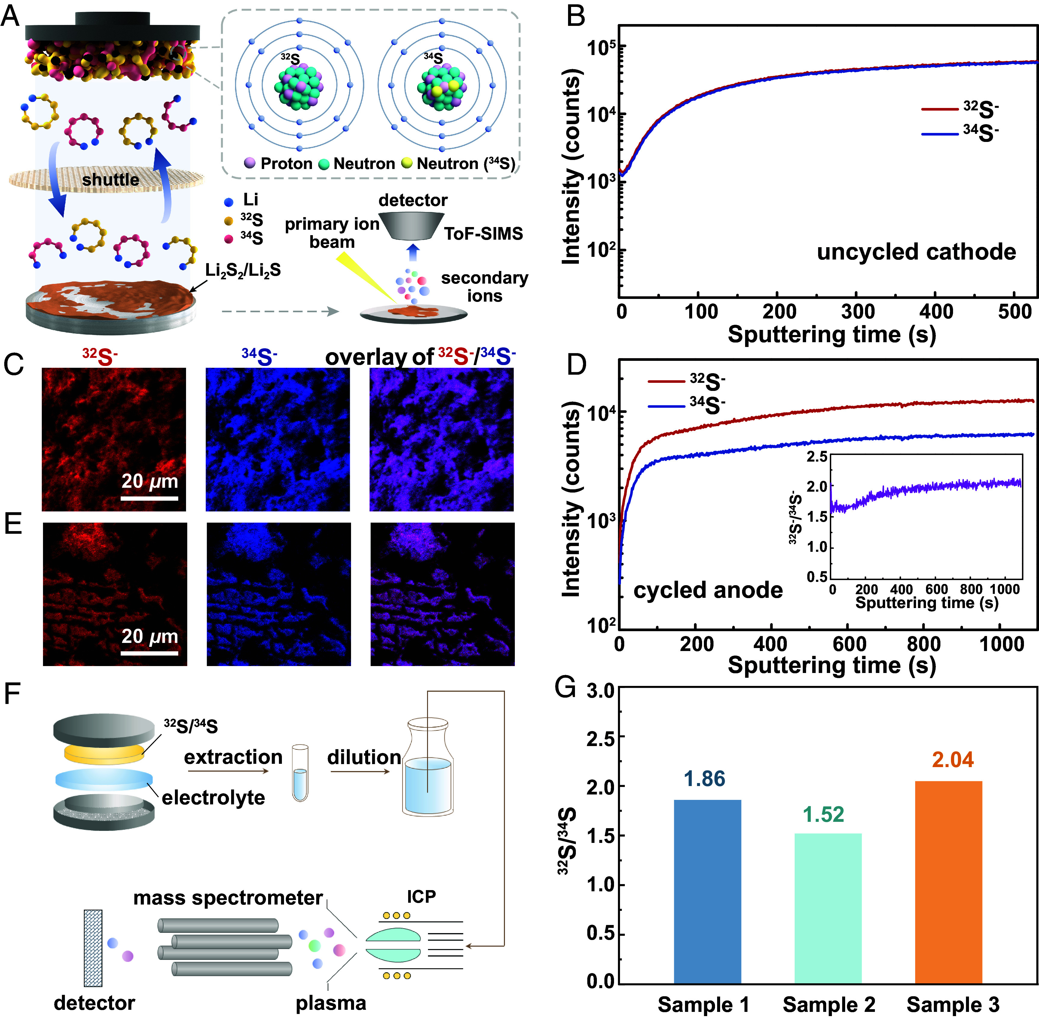
Spatial distribution and contents of S isotopes in the key components of a Li–S cell. (A) A schematic that illustrates the principle of the ToF-SIMS experiment. (B) Depth profile and (C) 2D planar images showing the distribution of isotopic S fragments at the uncycled 34S/32S@CMK-3 cathode. (D) Depth profile and (E) 2D planar images showing the distribution of isotopic S fragments at the cycled Li–metal anode; Inset of (D) shows the variation of 32S/34S (molar) ratio with sputtering time. (F) A schematic that illustrates the principle of the ICP-MS experiment. (G) Molar ratio of 32S to 34S in the cycled electrolyte.
A model study that shows insights into the LiPS–solvent interaction is critical for comprehending the above results. To simplify the study, we focus on the LiPS–DME interaction (as DOL shows similar interaction with LiPSs, and the salt anion is barely involved in the inner cation solvation sheath once solvent-separated ion pairs form) (44, 45). Calculated results (Fig. 4 A–C and SI Appendix, Table S7) demonstrate that the 34S-based soluble LiPSs, including Li234S8, Li234S6, and Li234S4, show higher solvation energy (Es) with DME than the 32S-based counterparts, though they share similar solvation structures. As such, dissolution of the 34S-based LiPSs into the electrolyte appears to be thermodynamically more preferred than that of the 32S-based LiPSs, which is contradictory to the experimental results that the 34S-based LiPSs show inhibited shuttle and lower solubility in the electrolyte. To precisely depict the solvation process and the interaction of LiPSs with solvent molecules, ab initio molecular dynamics (AIMD) simulations were performed on a Li2S6–DME system (SI Appendix, Fig. S13). According to the radial distribution function (RDF) profiles (Fig. 4 D and E and SI Appendix, Fig. S14), both Li234S6–DME and Li232S6–DME show similar interatomic interactions, including Li–X (“X” represents C/H/O atoms of the solvent), Li–S, and S–X. Cation–solvent (Li+–DME) and cation–anion (Li+-S62−) interactions account for the main chemical interactions that build the solute-solvent pair, which are respectively formed through Li–O coordination and Li–S bond. Li234S6–DME shows a stronger cation–solvent interaction (via Li–O) than Li232S6–DME (Fig. 4D). Such a strong interaction promotes the Li2S6 dissociation by the ether solvent, and it reasonably explains the high Es of 34S-based LiPSs in the presence of DME. The cation–anion interaction via Li–S is competitive to the cation–solvent interaction via Li–O. Provided with a stronger cation–solvent interaction, the Li234S6–DME shows a weaker cation–anion (Li–S) interaction than Li232S6–DME (Fig. 4E). In another S62− chain that contains three 34S atoms and three 32S atoms arranged in an alternant fashion, the 34S atom also shows a weaker interaction with Li than the 32S atom (SI Appendix, Fig. S15), where the force is contributed mainly by the terminal S. According to Kamphaus et al., the LiPSs barely exist in the form of Sn2− anions but mostly in the form of neutral molecules when they migrate between cathode and anode, i.e., the shuttle of polysulfide anions awfully builds on their attachment to the Li+ cation (44). Therefore, a weak cation–anion interaction in Li234S6 may help to suppress LiPS shuttle in the ether electrolyte compared with Li232S6. With the above results, it becomes clear that the 34S-based soluble LiPSs tend to quickly solvate yet slowly migrate in the ether electrolyte compared with the 32S-based LiPSs. For Li–S cells, the unique electrochemical properties of 34S would facilitate in situ formation and fixation of high-order LiPSs at the cathode–electrolyte interface, contributing to faster LiPS conversion kinetics via the solution-mediated pathway, as has been proven by the GITT and Li2S precipitation experiments. Rapid Li–34S conversion reaction at the cathode means improved conversion rate of high-order soluble LiPSs, which in turn contributes to their reduced solubility in the electrolyte and less low-order LiPS deposited at the anode. Consequently, the Li–34S cell shows much improved cycling stability.
Fig. 4.

Chemical interactions between soluble LiPSs and ether solvent of electrolyte. (A and B) AIMD snapshots taken from DME-solvated structures of (A) Li232S8, Li232S6, and Li232S4 and of (B) Li234S8, Li234S6, and Li234S4. (C) Es in DME of the above LiPSs. (D and E) RDF profiles that describe the interactions with DME of Li232S6 and Li234S6 via (D) Li–X and (E) Li–S.
To conclude, the (electro)chemical variations between stable S allotropes were studied and compared in a rechargeable Li–S battery. In the conventional form of cyclo-S8, the S molecule based on heavy isotope (34S) is thermodynamically more stable and shows stronger tendency to react with Li atom than the one based on light S (32S). The soluble LiPSs formed by Li uptake of cyclo-34S8 show a stronger cation–solvent interaction yet a weaker cation–anion interaction than the 32S-based counterparts, which accounts for quicker solvation yet more sluggish migration of LiPSs. Hence, the 34S-based cathode enables faster Li–S conversion reaction at the solid–liquid interface and inhibited shuttle of LiPSs in the electrolyte. In this way, the Li–34S cell simultaneously features improved cathode reaction kinetics and cycling stability compared with the Li–32S cell. Though the 34S cathode involves with retarded kinetics of solid-phase LiPS conversion, the issue could be addressed through applying a proper (dis)charge protocol that fits battery operation at different SOC [e.g., by applying a smaller (dis)charge rate at a low state of charge]. Another potential issue regarding the cathode use of heavy 34S could be a reduced cell-level specific energy. According to SI Appendix, Table S8, a 10-Ah Li–S pouch cell could lose ~2.6% of cell energy by switching from the 32S cathode to the 34S cathode. However, since the 34S cathode shows much inhibited LiPS shuttle and more stable cycling performance than the 32S cathode, the gap between battery energy could be gradually closed after several (dis)charge cycles. Note that 34S accounts for 1/25 to 1/20 of total S in nature, the heavy S isotope could claim a comparable mass abundance with the common metal elements in the earth’s crust such as copper or zinc (46), making it a promising material for battery and related industries.
Finally, the insights into the electrochemistry of S isotopes offer a perspective on heavy isotope separation, a key technology that enables large-scale manufacture and use of stable isotopes. Although stable S isotopes (mostly 34S) can be separated from nature S via the conventional chemical exchange or distillation approaches (17), the separation technology usually involves a low separation factor (mostly <1.04), a long separation time and complicated procedures (2, 47, 48), which notably raise the manufacturing cost of the isotopes. By taking the advantage of electrochemical isotope effects of S, our simple demonstration on a Li–S battery shows promises to readily achieve a higher separation factor (α) of 1.1 to 1.2 after 1 (dis)charge cycle and 1.6 to 2.0 after 10 (dis)charge cycles (SI Appendix, Figs. S16 and S17 and Note S4). With properly designed electrolyte composition, cathode structure, and (dis)charge protocols, one could expect a magnified isotope effect that leads to a higher separation ratio of S isotopes. The other two stable S isotopes show relatively low abundances in natural S (33S: 0.75 at.% and 36S: 0.01 at.%), and it remains difficult to directly study their influence on Li–S electrochemistry in a coin cell. Use of a proper battery configuration, such as an Ah-level pouch cell with a high areal mass loading of S at the cathode, may help to magnify the isotope effects of 33S/36S and enrich the rare isotopes at different cell components. The current study could inspire interdisciplinary field of isotope electrochemistry that not only triggers science for existing electrochemical systems but also the development of isotope-related technology.
Materials and Methods
Preparation of 32S@CMK-3 and 34S@CMK-3.
In a typical synthesis, α-32S (or natural S, Sigma-Aldrich, analytical reagent) powder was thoroughly mixed with the CMK-3 mesoporous carbon (Nanjing XFNANO Materials) at a mass ratio of mS:mC=60:40. In the control experiment, α-34S (Cambridge Isotope Laboratories, Inc., 99.79%) powder was mixed with CMK-3 at a mass ratio of mS:mC=64:40. The mass ratio of natural S (and 34S isotope) to CMK-3 on the cathode is precisely controlled so that both cathodes have an equal number of moles of total S isotopes. The above mixtures were sealed in an argon-prefilled container and maintained at 150 °C for 10 h. After being cooled down to room temperature, the 32S@CMK-3 and 34S@CMK-3 were prepared.
Preparation of 34S/32S@CMK-3.
In a typical synthesis, 34S, 32S, and CMK-3 were thoroughly mixed at a mass ratio of mS-34:mS-32:mC=206:194:600. The mixture was sealed in the Ar-prefilled container and maintained at 150 °C for 10 h. After being cooled down to room temperature, the 34S/32S@CMK-3 was prepared.
Preparation of the S Electrodes.
To prepare the 32S@CMK-3 and 34S@CMK-3 electrodes, the as-prepared S–C composites, super-P conductive additives (Cabot) and poly(vinylidene fluoride) binder (Alfa Aesar) were mixed at a mass ratio of 8:1:1 in a 1-methyl-2-pyrolidone solvent (Alfa Aesar, 99.5%) to form a uniform slurry. The slurry was then casted onto a carbon-coated Al foil (Guangzhou Nanuo New Materials Technology Co., Ltd.) and dried at 60 °C for 24 h. The dried foil was cut into slices with a diameter of 10 mm and an areal S mass loading of 1.5 mg cm−2. The preparation of the 34S/32S@CMK-3 electrode follows an almost identical procedure with the above 32S@CMK-3 electrode, except for a reduced areal S mass loading of 0.5 mg cm−2.
Preparation of the Li–S Cells.
CR2032-type coin cells were assembled in an Ar-filled glove box (Mikrouna, with H2O and O2 contents of <0.1 ppm). All experimental materials were dried at 60 °C for 2 h before battery assembly. To prepare the Li–32S@CMK-3 (or Li–34S@CMK-3) cell, the as-prepared S electrode (as the cathode) was paired with a 10-mm-in-diameter Li–metal disc (China Energy Lithium Co., Ltd. 99.9%) as the anode. A trilayer polypropylene/polyethylene/polypropylene composite polymer separator (Celgard, ~25 μm thick) was sandwiched between the two electrodes, which was filled by 50 μL of an ether electrolyte. The electrolyte consists of 1M bis(trifluoromethane)sulfonimide Li salt (LiTFSI, Sigma-Aldrich, 99.99%) in an equivoluminal mixture of DOL (Sigma-Aldrich, 99.8%) and DME (Sigma-Aldrich, 99.5%), with addition of 1 wt.% lithium nitrate (LiNO3, Alfa, anhydrous, 99.98%). To prepare the Li–34S/32S@CMK-3 cell, a glass fiber (Whatman, ~650 μm thick) was sandwiched between the two electrodes, which was filled by 180 μL of an ether electrolyte consisting of 1M lithium perchlorate (LiClO4, 99.99%, Sigma-Aldrich) in the equivoluminal DOL/DME mixture.
Material Characterization.
The morphology and elemental distribution of S–C composites were characterized by a SEM (JOEL JSM-6701F) operated at 10 kV and a TEM (JEM-2100F) coupled with an energy-dispersive X-ray spectrometer. The XRD patterns were collected using a Philips PW3710 (Rigaku D/max-2500 diffractometer) with filtered Cu Kα radiation (λ = 1.5418 Å) within a 2θ range of from 10° to 80° (scan rate: 5° min−1). TG profiles were collected on a Netzsch thermal gravimetric analyzer (TG/DTA6300) from room temperature to 800 °C (heating rate: 10 °C min−1) under the N2 atmosphere. Raman spectra of α-32S and α-34S powders were collected on a HORIBA spectrometer (LabRAM HR Evolution) with a 532-nm excitation laser and a 100× long-distance objective. Differential scanning calorimetry (DSC) was performed on a Netzsch DSC 214 Polyma from room temperature to 210 °C (heating rate: 5 °C min−1). N2 absorption and desorption isotherms were obtained at 77.3 K with a Autosorb-iQ surface area pore size analyzer, and the ASIQ Win software (Quantachrome Instruments Version 11.04) was used to analyze the physisorption isotherms and determine the pore parameters.
Electrochemical Measurements.
The electrochemical measurements of Li–S cells were carried out on a NEWARE CT-4008 battery tester. For the Li–32S@CMK-3 (or Li–34S@CMK-3) cell, a voltage range of 1.8 to 2.8 V (versus Li+/Li) and a C-rate of 0.2C were employed, where 1C was defined as 1,675 mA/g for 32S and 1,576 mA/g for 34S. For the Li–34S/32S@CMK-3 cell, a voltage range of 1.5 to 2.8 V (versus Li+/Li) and a C-rate of 0.1C was employed, where 1C was defined as 1,624 mA/g. GITT was employed to study the cathode reaction kinetics in the Li–32S@CMK-3 (or Li–34S@CMK-3) cell, which was performed by applying a constant discharge current of 0.1C for 30 min, followed by a 10-h relaxation. Li2S precipitation experiments were conducted on a Princeton electrochemical workstation by applying a potentiostatic process at 2.09 V on a Li–S cell after galvanostatic discharge from open-circuit voltage to 2.11 V at a current of 0.1 mA.
Characterization of S Isotopes.
Before the experiment, the Li–34S/32S@CMK-3 cell was applied with 10 discharge–charge cycles and was disassembled in the Ar-filled glovebox. The cycled Li–metal anode was taken out of the cell and dried in vacuum overnight. The electrolyte was extracted from the cycled cell and diluted with isopropanol (Acros, 99.5%) by 400 times. A ToF-SIMS instrument (ION-ToF GmbH, Münster, Germany) equipped with a 30-keV Bi3+ primary ion gun and a 2-keV Cs+ sputter gun were employed to collect signals of 34S− and 32S− ions from both the uncycled 34S/32S@CMK-3 cathode and the cycled Li–metal anode. An electron flood gun was used for charge neutralization. The raster size of the image was 50 × 50 μm and the sputter area was 100 × 100 μm. The 32S−/34S− ratio of the electrolyte was examined by an ICP-MS (Agilent 8900), where the uncycled electrolyte was employed as a blank sample.
Theoretical Calculation.
All calculations were performed using the plane wave-based periodic DFT method, which was implemented in the Vienna Ab Initio Simulation Package (49, 50). The electron–ion interaction was described with the projector augmented wave method (51, 52). The electron exchange and correlation energies were treated within the generalized gradient approximation in the Perdew–Burke–Ernzerhof functional (53). The plane wave basis was set up to 500 eV. AIMD was carried out to obtain configurations (54). The AIMD task was performed over 90,000 steps in the NVT ensembles at 300 K, using a small-time step of 0.1 fs due to the lightweight of H+.
Supplementary Material
Appendix 01 (PDF)
Acknowledgments
This work was supported by Beijing Natural Science Foundation (Grant Nos. JQ22005 and 2232034), the National Key R&D Program of China (Grant No. 2019YFA0705703), the Basic Science Center Project of National Natural Science Foundation of China (Grant No. 52388201), CAS Project for Young Scientists in Basic Research (Grant No. YSBR-058), National Natural Science Foundation of China (Grant Nos. 52172252, 21975266, 22209188, 22377130, 21927804, and 22005316), and the Young Elite Scientist Sponsorship Program by China Association for Science and Technology (2022QNRC001). We thank Ms. Wei Guo for providing ICP-MS facility supported by Agilent Technologies Co., Ltd.
Author contributions
S.X. conceived the project; Y.-G.G., S.X., and C.B. supervised the project; X.-T.L. and S.X. designed research; X.-T.L., Y. Zhao, and S.X. performed research; Y. Zhao contributed new analytic tools; X.-T.L., Y.-G.G., S.X., and C.B. analyzed data; X.-T.L., Y. Zhao, Y.-H.Z., W.-P.W., Y. Zhang, F.W., Y.-G.G., S.X., and C.B. discussed and revised the paper; and X.-T.L., Y.-H.Z., and S.X. wrote the paper.
Competing interests
The authors declare no competing interest.
Footnotes
Reviewers: Z.G., The University of Adelaide; F.L., Nankai University; and G.Y., The University of Texas at Austin.
Contributor Information
Sen Xin, Email: xinsen08@iccas.ac.cn.
Chunli Bai, Email: clbai@cas.cn.
Data, Materials, and Software Availability
All study data are included in the article and/or SI Appendix.
Supporting Information
References
- 1.Roduner E., “Muonium—An ultra-light isotope of hydrogen” in Isotope effects in chemistry and biology, Kohen A., Limbach H.-H., Eds. (CRC Press, 2005), pp. 433–448. [Google Scholar]
- 2.Boris M. A., Polevoi A. S., Separation of sulphur isotopes by physicochemical methods. Russ. Chem. Rev. 52, 213 (1983). [Google Scholar]
- 3.Zhang Y.-S., et al. , Ultra-fast uranium capture via the synergistic interaction of the intrinsic sulfur atoms and the phosphoric acid groups adhered to edge sulfur of MoS2. J. Hazard. Mater. 457, 131745 (2023). [DOI] [PubMed] [Google Scholar]
- 4.Karelin Y. A., et al. , Radionuclide production using a fast flux reactor. Appl. Radiat. Isot. 53, 825–827 (2000). [DOI] [PubMed] [Google Scholar]
- 5.Han H. S., Park U. J., Shin H. Y., Yoo K. M., “Method for distillation of sulfur for the preparing radioactive phosphorous nuclide.” US Patent 7266173B2 (2007).
- 6.Zhang M.-Y., Wang S.-J., Ma G.-Q., Zhou H.-Z., Fu J., Sulfur isotopic composition and source identification of atmospheric environment in central Zhejiang, China. Sci. China Earth Sci. 53, 1717–1725 (2010). [Google Scholar]
- 7.Ku T. C. W., Walter L. M., Coleman M. L., Blake R. E., Martini A. M., Coupling between sulfur recycling and syndepositional carbonate dissolution: Evidence from oxygen and sulfur isotope composition of pore water sulfate, South Florida Platform, U.S.A. Geochim. Cosmochim. Acta 63, 2529–2546 (1999). [Google Scholar]
- 8.Wynn J. G., Sumrall J. B., Onac B. P., Sulfur isotopic composition and the source of dissolved sulfur species in thermo-mineral springs of the Cerna Valley, Romania. Chem. Geol. 271, 31–43 (2010). [Google Scholar]
- 9.Chang Z.-S., Large R. R., Maslennikov V., Sulfur isotopes in sediment-hosted orogenic gold deposits: Evidence for an early timing and a seawater sulfur source. Geology 36, 971–974 (2008). [Google Scholar]
- 10.Forrest J., Klein J. H., Newman L., Sulphur isotope ratios of some power plant flue gases: A method for collecting the sulphur oxide. J. Chem. Technol. Biotechnol. 23, 855–863 (1973). [Google Scholar]
- 11.Albalat E., et al. , Sulfur isotope analysis by MC-ICP-MS and application to small medical samples. J. Anal. At. Spectrom. 31, 1002–1011 (2016). [Google Scholar]
- 12.Gregg C., Some application of stable isotopes in clinical pharmacology. Eur. J. Clin. Pharmacol. 7, 315–319 (1974). [DOI] [PubMed] [Google Scholar]
- 13.Albarede F., et al. , Medical applications of Cu, Zn, and S isotope effects. Metallomics 8, 1056–1070 (2016). [DOI] [PubMed] [Google Scholar]
- 14.Ward A. T., Raman spectroscopy of sulfur, sulfur-selenium, and sulfur-arsenic mixtures. J. Phys. Chem. 72, 4133–4139 (1968). [Google Scholar]
- 15.Domingo C., Montero S., Raman intensities of sulphur α-S8. J. Chem. Phys. 74, 862–872 (1981). [Google Scholar]
- 16.Eckert B., Albert H., Jodl H., Foggi P., Raman studies of sulfur crystal (α-S8) at high pressures and low temperatures. J. Phys. Chem. 100, 8212–8219 (1996). [Google Scholar]
- 17.Hayes J. M., Practice and principles of isotopic measurements in organic geochemistry. Org. Geochem. Contemporaneous Ancient Sediments 5, e5 (1983). [Google Scholar]
- 18.Yin Y.-X., Xin S., Guo Y.-G., Wan L.-J., Lithium-sulfur batteries: Electrochemistry, materials, and prospects. Angew. Chem. Int. Ed. Engl. 52, 13186–200 (2013). [DOI] [PubMed] [Google Scholar]
- 19.Wang N., et al. , Thickness-independent scalable high-performance Li-S batteries with high areal sulfur loading via electron-enriched carbon framework. Nat. Commun. 12, 4519 (2021). [DOI] [PMC free article] [PubMed] [Google Scholar]
- 20.Zhang J., et al. , Nanostructured host materials for trapping sulfur in rechargeable Li–S batteries: Structure design and interfacial chemistry. Small Methods 2, 1700279 (2018). [Google Scholar]
- 21.Xu R., Lu J., Amine K., Progress in mechanistic understanding and characterization techniques of Li-S batteries. Adv. Energy Mater. 5, 1500408 (2015). [Google Scholar]
- 22.Chou J., Wang Y.-H., Wang W.-P., Xin S., Guo Y.-G., Asymmetric electrode-electrolyte interfaces for high-performance rechargeable lithium-sulfur batteries. J. Electrochem. 29, 2217009 (2023). [Google Scholar]
- 23.Rosenman A., et al. , Review on Li-Sulfur battery systems: An integral perspective. Adv. Energy Mater. 5, 1500212 (2015). [Google Scholar]
- 24.Chen Y.-Z., et al. , Polysulfide filter and dendrite inhibitor: Highly graphitized wood framework inhibits polysulfide shuttle and lithium dendrites in Li–S batteries. Adv. Funct. Mater. 31, 2102458 (2021). [Google Scholar]
- 25.Feng L.-X., et al. , Regulating polysulfide diffusion and deposition via rational design of core–shell active materials in Li–S batteries. ACS Nano 16, 7982–7992 (2022). [DOI] [PubMed] [Google Scholar]
- 26.Diao Y., Xie K., Xiong S.-Z., Hong X.-B., Shuttle phenomenon–The irreversible oxidation mechanism of sulfur active material in Li-S battery. J. Power Sources 235, 181–186 (2013). [Google Scholar]
- 27.Mikhaylik Y. V., Akridge J. R., Polysulfide shuttle study in the Li/S battery system. J. Electrochem. Soc. 151, A1969–A1976 (2004). [Google Scholar]
- 28.Zheng D., et al. , Investigation of the Li-S battery mechanism by real-time monitoring of the changes of sulfur and polysulfide species during the discharge and charge. ACS Appl. Mater. Interfaces 9, 4326–4332 (2017). [DOI] [PubMed] [Google Scholar]
- 29.Seo H. K., et al. , Direct visualization of lithium polysulfides and their suppression in liquid electrolyte. Nano Lett. 20, 2080–2086 (2020). [DOI] [PubMed] [Google Scholar]
- 30.Huang Y.-H., Wen B., Jiang Z.-L., Li F.-J., Solvation chemistry of electrolytes for stable anodes of lithium metal batteries. Nano Res. 16, 8072–8081 (2023). [Google Scholar]
- 31.Stefaniak W., Goworek J., Biliński B., Pore size analysis by nitrogen adsorption and thermal desorption. Colloids Surf. A Physicochem. Eng. Asp. 214, 231–237 (2003). [Google Scholar]
- 32.Li Z.-T., Liu D.-M., Cai Y.-D., Wang Y.-P., Teng J., Adsorption pore structure and its fractal characteristics of coals by N2 adsorption/desorption and FESEM image analyses. Fuel 257, 116031 (2019). [Google Scholar]
- 33.Ji Z., et al. , Anchoring lithium polysulfides via affinitive interactions: Electrostatic attraction, hydrogen bonding, or in parallel? J. Phys. Chem. C 119, 20495–20502 (2015). [Google Scholar]
- 34.Tian D., et al. , Heterogeneous mediator enabling three-dimensional growth of lithium sulfide for high-performance lithium-sulfur Batteries. Energy Environ. Mater. 5, 1214–1221 (2022). [Google Scholar]
- 35.Yan R., et al. , Origin and acceleration of insoluble Li2S2–Li2S reduction catalysis in ferromagnetic atoms-based lithium-sulfur battery cathodes. Angew. Chem. Int. Ed. Engl. 62, e202215414 (2023). [DOI] [PMC free article] [PubMed] [Google Scholar]
- 36.Barghamadi M., et al. , Lithium–sulfur batteries—The solution is in the electrolyte, but is the electrolyte a solution? Energy Environ. Sci. 7, 3902–3920 (2014). [Google Scholar]
- 37.Moy D., Manivannan A., Narayanan S., Direct measurement of polysulfide shuttle current: A window into understanding the performance of lithium-sulfur cells. J. Electrochem. Soc. 162, A1–A7 (2014). [Google Scholar]
- 38.Kavčič M., et al. , Operando resonant inelastic X-ray scattering: An appropriate tool to characterize sulfur in Li–S batteries. J. Phys. Chem. C 120, 24568–24576 (2016). [Google Scholar]
- 39.Ji X.-L., Lee K. T., Nazar L. F., A highly ordered nanostructured carbon-sulphur cathode for lithium-sulphur batteries. Nat. Mater. 8, 500–506 (2009). [DOI] [PubMed] [Google Scholar]
- 40.Yuan B., Aitken B., Sen S., Is the lambda-transition in liquid sulfur a fragile-to-strong transition? J. Chem. Phys. 151, 041105 (2019). [DOI] [PubMed] [Google Scholar]
- 41.Stashick M. J., Marriott R. A., Viscoelastic behavior corresponding to reptative relaxation times across the lambda-transition for liquid elemental sulfur. J. Chem. Phys. 152, 044503 (2020). [DOI] [PubMed] [Google Scholar]
- 42.Ruiz-Garcia J., Anderson E. M., Greer S. C., Shear viscosity of liquid sulfur near the polymerization temperature. J. Phys. Chem. 93, 6980–6983 (2002). [Google Scholar]
- 43.Greenwood N. N., Earnshaw A., “Chapter 15: Sulfur” in Chemistry of the Elements, N. N. Greenwood, A. Earnshaw, Eds. (Butterworth-Heinemann, 1997), pp. 645–746. [Google Scholar]
- 44.Kamphaus E. P., Balbuena P. B., First-principles investigation of lithium polysulfide structure and behavior in solution. J. Phys. Chem. C 121, 21105–21117 (2017). [Google Scholar]
- 45.Rajput N. N., et al. , Elucidating the solvation structure and dynamics of lithium polysulfides resulting from competitive salt and solvent interactions. Chem. Mater. 29, 3375–3379 (2017). [Google Scholar]
- 46.Peter B. N. T., Mohr J., Newell D. B., “Atomic masses and abundances” in CRC Handbook of Chemistry and Physics, Haynes W. M., Ed. (CRC Press, 2016), pp. 12–15. [Google Scholar]
- 47.North E. D., White R. R., Separation of the stable isotope of sulfur 34. Ind. Eng. Chem. 43, 2390–2397 (1951). [Google Scholar]
- 48.Mills T. R., Practical sulfur isotope separation by distillation. Sep. Sci. Technol. 25, 1919–1930 (1990). [Google Scholar]
- 49.Kresse G., Furthmüller J., Efficiency of ab-initio total energy calculations for metals and semiconductors using a plane-wave basis set. Comput. Mater. Sci. 6, 15–50 (1996). [Google Scholar]
- 50.Kresse G., Furthmüller J., Efficient iterative schemes for ab initio total-energy calculations using a plane-wave basis set. Phys. Rev. B 54, 11169–11186 (1996). [DOI] [PubMed] [Google Scholar]
- 51.Blöchl P. E., Projector augmented-wave method. Phys. Rev. B 50, 17953 (1994). [DOI] [PubMed] [Google Scholar]
- 52.Kresse G., Joubert D., From ultrasoft pseudopotentials to the projector augmented-wave method. Phys. Rev. B 59, 1758–1775 (1999). [Google Scholar]
- 53.Perdew J. P., Burke K., Ernzerhof M., Generalized gradient approximation made simple. Phys. Rev. Lett. 77, 3865 (1996). [DOI] [PubMed] [Google Scholar]
- 54.Deng Z., Zhu Z.-Y., Chu L.-H., Ong S. P., Data-driven first-principles methods for the study and design of alkali superionic conductors. Chem. Mater. 29, 281–288 (2017). [Google Scholar]
Associated Data
This section collects any data citations, data availability statements, or supplementary materials included in this article.
Supplementary Materials
Appendix 01 (PDF)
Data Availability Statement
All study data are included in the article and/or SI Appendix.