Abstract
MRI is a noninvasive, ionizing radiation-free imaging modality that has become an indispensable medical diagnostic method. The literature suggests MRI as a potential diagnostic modality in dentomaxillofacial radiology. However, current MRI equipment is designed for medical imaging (eg, brain and body imaging), with general-purpose use in radiology. Hence, it appears expensive for dentists to purchase and maintain, besides being complex to operate. In recent years, MRI has entered some areas of dentistry and has reached a point in which it can be provided following a tailored approach. This technical report introduces a dental-dedicated MRI (ddMRI) system, describing how MRI can be adapted to fit dentomaxillofacial radiology through the appropriate choice of field strength, dental radiofrequency surface coil, and pulse sequences. Also, this technical report illustrates the possible application and feasibility of the suggested ddMRI system in some relevant diagnostic tasks in dentistry. Based on the presented cases, it is fair to consider the suggested ddMRI system as a feasible approach to introducing MRI to dentists and dentomaxillofacial radiology specialists. Further studies are needed to clarify the diagnostic accuracy of ddMRI considering the various diagnostic tasks relevant to the practice of dentistry.
Keywords: magnetic resonance imaging, dentistry, diagnostic imaging
Introduction
Diagnostic imaging is essential in dentistry to provide relevant anatomical information and determine the presence and extent of disease in conjunction with clinical examination.1 It affects all aspects of oral health, from detecting and monitoring disease progression to treatment planning and assessment of treatment efficacy.1 However, ionizing radiation-based imaging modalities dominate dental practice, despite the drawbacks of incrementally irradiating patients during a lifetime.1,2 Ultimately, the use of 3D imaging (mostly cone beam CT, CBCT) improved the comprehension of anatomical structures and pathological conditions.3 However, although CBCT protocols have been suggested within a “low dose” range (eg, <10 µSv), exposure to ionizing radiation is inevitable.4 Diagnostics in dentistry can benefit from a transition to imaging modalities free of ionizing radiation,5,6 which, among other advantages, would permit the follow-up of patients without the concerns related to the stochastic risks of the traditional imaging modalities.7
Another limitation of the imaging modalities used in dentistry is the poor visualization of the soft tissues.8 For example, the inferior alveolar nerve (IAN) depiction in panoramic images and CBCT volumes is limited to the cortical bone surrounding the nerve rather than the nerve itself.2 Also, traditional 2D and 3D ionizing radiation-based imaging modalities cannot delineate early preclinical inflammatory changes, which are restricted to the soft tissue components of bone and typically precede bone loss.9 Substantial bone degeneration (30%-50% mineral loss) is necessary to identify periapical and periodontal lesions radiographically.4
MRI is a noninvasive and ionizing radiation-free imaging modality.5,6 A recent systematic review showed that MRI can display dentomaxillofacial structures and related pathologies across various indications and specialities in dentistry.5 Technical developments are required to increase the ability of MRI scanners to serve function in a point of care role to meet dentists’ needs and reduce equipment costs.10 Also, to provide image acquisition protocols capable of managing the diagnostic tasks in dentomaxillofacial radiology.10 These developments must include software (ie, pulse sequences) and hardware (eg, radiofrequency coils) tailored to fit dentomaxillofacial anatomy (eg, fields-of-view size and image resolution) and patients’ demands (eg, comfortable positioning and short examination time). Finally, these systems must be safe and easy to use by the existing “dental” staff.10
This technical report introduces the concept of a “dental-dedicated MRI” (ddMRI) system, which explicitly tailors the hardware, software, and workflow for dentomaxillofacial indications. The feasibility of the suggested ddMRI system in manifold diagnostic tasks relevant to dentomaxillofacial radiology is addressed.
Methods
Study setting
The present report proposes a ddMRI system that uses a commercially available, wide-bore, low-field strength MR scanner equipped with a dental radiofrequency surface coil and customized software (eg, pulse sequences) configuration.
Ongoing clinical trials are collecting evidence to validate ddMRI for relevant diagnostic tasks in a collaborative effort between universities and life-science industry partners. To illustrate this technical report, images acquired from patients included in those clinical trials were selected. These images were acquired at the Section for Oral Radiology and Endodontics, Department of Dentistry and Oral Health, Aarhus University, Aarhus, Denmark. The patients signed an informed consent regarding the acquisition of the images, and the protocol for the study was approved by the regional ethics committee (# 1-10-72-101-22).
Study population
For safety reasons, not all patients are eligible for MRI acquisition. Patients with pronounced claustrophobia, who were pregnant, those with implanted devices (eg, pacemakers, defibrillators, pumps), and who have metal shrapnel injuries of the eyes or MRI incompatible metallic inclusions or implants, large tattoos, and nonremovable metallic piercings were judged not eligible for imaging. Questions about these topics were part of the information provided to the patients when explaining the image acquisition during the consenting process.
Scanner platform
A recently developed MRI system (Magnetom Free.Max, Siemens Healthcare, Erlangen, Germany), operating at 0.55 T was used. Due to the lower field strength magnetic shielding requirements are reduced, and the siting constraints have been significantly lowered by avoiding the previously mandatory quench pipe. The system does not need helium refills (it requires 0.7 L of helium for operation) and has a reduced power consumption and water cooling requirement compared to 1.5-T scanners. The system weighs 3200 kg (substantially lighter than other commercially available clinical MRI systems), requires a room size of 24 m2, and includes a wider inner bore (80 cm in diameter), providing more openness and patient comfort.
Radiofrequency coil
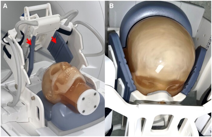
A prototype dental radiofrequency surface coil fitted to the face was designed to enhance the applicability of the selected scanner platform for the requested diagnostic tasks (Dental Coil, RAPID Biomedical, Rimpar, Germany). The arrangement comprises a 7-channel radiofrequency coil array with an open central element in a rigid housing and flexible extensions on both sides (eg, “wings”). These “wings” are bendable, made from durable material, and were designed to softly touch the patient’s face to ensure the coil elements are close to the region of interest. The coil array is mounted to a holder structure, enabling both a vertical and horizontal adjustment of the coil position, in addition to an angular adjustment to fit the patient’s face. The upper part of the holder structure is attached via a hinge, and therefore can be opened to facilitate patient positioning. The coil design provides patient comfort while helping to stabilize the patient’s head. Also, the coil was designed to provide sensitivity over the dentomaxillofacial area, minimizing signal collection from other regions that are not interesting from a diagnostic perspective (Figure 1). The array of individual coil elements is arranged in a suitable layout for parallel imaging, which is an approach commonly used to accelerate image acquisition. This is achieved by simultaneous detection of the signal from multiple receiver coils in combination with signal unfolding in the reconstruction process based on the sensitivity profile of each coil element.11
Figure 1.
ddMRI surface radiofrequency coil. The coil has bendable “wings” to ensure the receiving elements are close to the patient (red arrows in A). The coil geometry is optimized for highest sensitivity in the dentomaxillofacial area (B). ddMRI = dental-dedicated MRI.
Pulse sequences
The critical difference between MRI and traditional ionizing radiation-based modalities is that the latter depends solely on X-ray attenuation by matter, while MRI depicts an extensive range of observables. MRI pulse sequences are a set of radiofrequency pulses, gradient waveforms and signal detection periods that, with the appropriate choice of parameters, allow for the manipulation of image contrast, enabling a clearer distinction between different tissues and pathologies due to variations in signal intensities.12
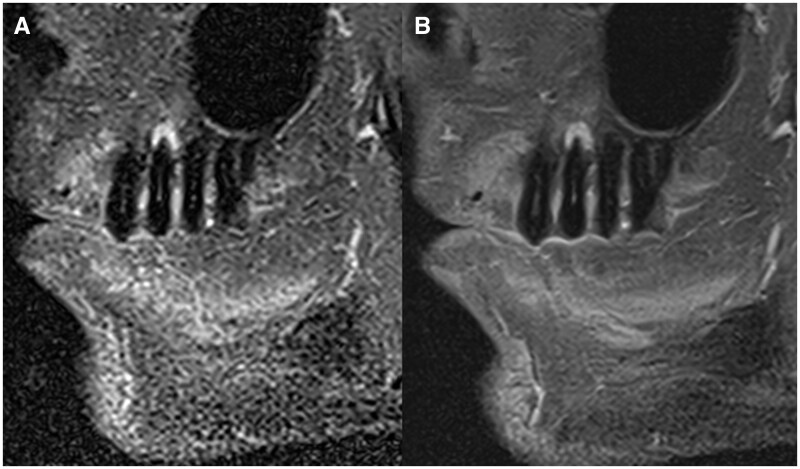
A set of pulse sequences was designed to fit the most common diagnostic tasks in dentistry [eg, orthodontic planning, diagnosis of temporomandibular joint (TMJ) disorders, diagnosis of bone loss and inflammatory changes associated with endodontic and periodontal diseases and planning of the extraction of impacted third molars]. These sequences were optimized to have the shortest possible acquisition time (minimizing scanning time), cover the region of interest without excesses (ie, restricted field of view—“FOV”), and provide adequate image resolution and contrast. To fulfil these requirements and enable ddMRI, some essential technical advances were incorporated into the sequences. Methods like compressed sensing (CS) based scan acceleration13 and advanced reconstruction algorithms employing artificial intelligence (AI) were incorporated to enhance scan efficiency14 and are key features within the ddMRI protocol (Figure 2).
Figure 2.
Comparison of images acquired in the sagittal orientation in a subject with an apical lesion in tooth 25. Both images were acquired with pulse sequences sensitive to inflammatory changes in the bone (ie, fat suppression). In (A), the image was obtained with conventional image acquisition techniques, and in (B), the image was reconstructed using a deep learning-based image algorithm that results in denoized images.
To fit to demands of each diagnostic task, some pulse sequences provide 3D, volumetric outputs, while others result in 2D image slabs. The 3D volumes are based on proton density (PD)-weighted pulse sequences optimized to visualize the dentomaxillofacial anatomy, while the 2D acquisitions were configured with either T1, T2, or PD weightings, depending on the diagnostic task. Fat suppression was used as appropriate, particularly to investigate signs of inflammation. The scanning protocol details suggested for ddMRI are provided in Table 1, for the tested diagnostic tasks. Details regarding the pulse sequences used for each diagnostic task are summarized in Table 1. The output DICOM files for those sequences ranged from 3 to 70 megabytes, considering the 2D image slabs and the 3D volumes, respectively. Image reconstruction time was typically only a few seconds and was always below 1 min for all used sequences.
Table 1.
Suggested ddMRI protocols for the tested diagnostic tasks.
| Diagnostic task | Use | Basic description | 3D/2D (planes) | Reconstructed resolution (mm) | FOV dimensions (h × w × d, mm) | Acquisition time | Basic scan parameters |
|---|---|---|---|---|---|---|---|
| Scout | Anatomy | T1 (GRE-VIBE) | 3D | 1.4 × 1.4 × 1.0 | 260 × 260 × 192 | 1′10″ | TR 8.1 ms, TE 2.25 ms, FA 12°, bandwidth 540 Hz/pixel, GRAPPA acceleration (×2), averages 1 |
| Orthodontics | Anatomy | PD (SPACE) | 3D | 0.4 × 0.4 × 0.7 | 160 × 160 × 144 | 3′23″ | TR 750 ms, TE 34 ms, FA 175°, bandwidth 284 Hz/pixel, CS acceleration (×3.5), averages 1.4 |
| TMJ | Anatomy | PD (TSE) T1 (TSE) T2 (TSE) | 2D (S, C) | 0.2 × 0.2 × 2.5 | 60 × 60 × 27.5 (bilateral) |
|
|
| Inflammation | PD-FS (TSE) | 2D (S, C, A) | 0.4 × 0.4 × 2.5 | 60 × 60 × 27.5 (bilateral) | 3′07″ | TR 2380 ms, TE 47 ms, FA 150°, bandwidth 100 Hz/pixel, GRAPPA acceleration (×3), averages 2 | |
| Tooth extraction/endodontic assessment/periodontal assessment | Anatomy | PD (TSE) | 2D (S, C, A) | 0.3 × 0.3 × 2 | 60 × 60 × 22 (unilateral) | 2′38″ | TR 2400 ms, TE 48 ms, FA 150°, bandwidth 100 Hz/pixel, GRAPPA acceleration (x3), averages 4 |
| Anatomy | PD (SPACE) | 3D | 0.4 × 0.4 × 0.7 | 60 × 60 × 67 | 3′09″ | TR 750 ms, TE 29 ms, FA 170°, bandwidth 284 Hz/pixel, CS acceleration (×4.2), averages 1.4 | |
| Inflammation | T2-STIR (TSE) | 2D (S, C, A) | 0.4 × 0.4 × 2.0 | 60 × 60 × 22 (unilateral) | 3′08″ | TR 2560 ms, TE 48 ms, FA 130°, bandwidth 106 Hz/pixel, GRAPPA acceleration (×3), averages 6 |
The scout acquisition was always present.
A = axial; C = coronal; CS = compressed sensing; ddMRI = dental-dedicated MRI; FA = flip angle; FOV = field of view; FS = fat-suppressed; GRAPPA = generalized auto-calibrating partially parallel acquisition; GRE = gradient echo; PD = proton density; S = sagittal; SPACE = sampling perfection with application-optimized contrast using different flip angle evolutions; STIR = short-tau inversion recovery; TE = time to echo; TMJ = temporomandibular joint; TR = repetition time; TSE = turbo spin-echo; VIBE = volumetric interpolated breath-hold examination.
Image acquisition workflow
The suggested ddMRI system offers a simplified workflow that follows the exact arrangement dentists use: scout image acquisition, FOV delimitation, and definition of image quality characteristics (ie, pulse sequences). The suggested approach is analogous to that already available for MRI of other body parts (eg, brain and knee) but tailored and restricted to the dentomaxillofacial area.
As a routine, the examination begins with a “scout,” which permits the identification of individual teeth, the location of the TMJ, bone and facial boundaries, and skeletal landmarks. The steps that follow the scout acquisition are defined based on the diagnostic task: in some tasks, a higher resolution 3D volume with a large FOV (eg, for orthodontic planning, Figure 3); for other tasks, a set of higher resolution multiplane 2D acquisitions with smaller FOVs, depicting the region of interest in 1 or more standard planes (eg, endodontic assessment, Figure 4). For some tasks, a bilateral, simultaneous acquisition is standard (eg, TMJ assessment). Details regarding each diagnostic task included in this technical report are presented in Table 1.
Figure 3.
ddMRI scout image, in the sagittal (A), coronal (B), and axial (C) planes, highlighting the definition of a large FOV (eg, for orthodontic planning purposes). A large FOV (15 cm × 15 cm × 15 cm) was determined following the patient’s anatomy, and it was aligned according to the cephalometric points Nasion, Sella, Basion, and Mentum. ddMRI = dental-dedicated MRI; FOV = field of view.
Figure 4.
ddMRI scout image, in the sagittal (A), coronal (B), and axial (C) planes, highlighting the FOV definition for endodontic purposes. A small FOV (60 mm × 60 mm x 25 mm) was determined following the tooth’s (mandibular molar) anatomy, to acquire a set of para-sagittal images. ddMRI = dental-dedicated MRI; FOV = field of view.
Results
Orthodontic planning
The suggested ddMRI system is being assessed for use providing the needed diagnostic information in orthodontics, including lateral cephalograms and panoramic reconstructions derived from image volumes, that can be used to annotate cephalometric points, assess the patient’s soft tissue profile, and provide an overview of the upper airways.7 It provides adequate coverage to allow proper diagnosis regarding the maxillary and mandibular position, facial proportions/vertical relationships, incisor positions (maxillary and mandibular), and the airway status.7 Several images may be necessary during treatment for monitoring or after treatment completion for evaluation of the results.7 With ddMRI this could be done without additional radiation exposure to the patient.
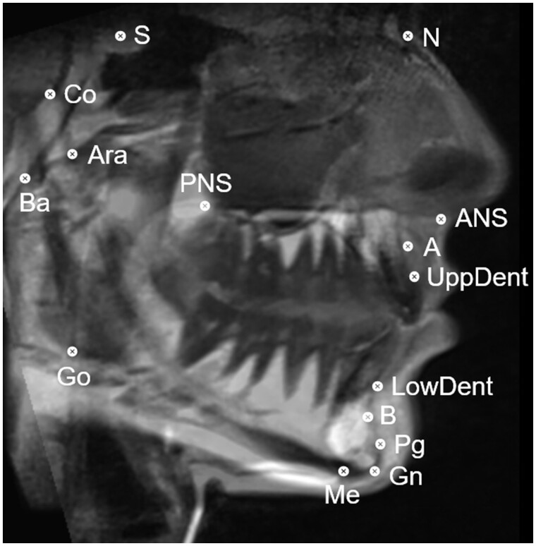
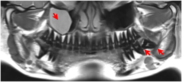
In the present approach, a 3D volume was acquired and adjusted to provide a cephalometric image based on the sagittal plane, from which the traditional cephalometric points can be annotated (Figure 5). Also, based on the sagittal view, the patient’s soft tissue and the airway profile were defined (ie, traced) (Figure 6). The same volume provided a panoramic reconstruction, from which other pathologies can also be identified (Figure 7).
Figure 5.
ddMRI sagittal view reconstructed from a 3D volumetric acquisition. Cephalometric points were annotated: S (sella), N (nasion), ANS (anterior nasal spine), A-point, UppDent (upper dental), LowDent (lower dental), B-point, Pg (pogonion), Gn (gnathion), Me (mentum), Go (gonion), PNS (posterior nasal spine), Ara (articulare anterior), Ba (basion), and Co (condylion). ddMRI = dental-dedicated MRI.
Figure 6.
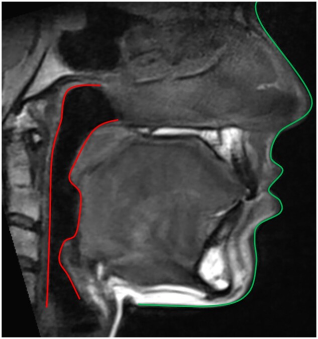
ddMRI sagittal view reconstructed from a 3D volumetric acquisition, in which the patient’s soft tissue (green) and airway (red) profiles were traced. ddMRI = dental-dedicated MRI.
Figure 7.
ddMRI panoramic view, reconstructed from a 3D volumetric acquisition. Presence of a mucous retention cyst in the right maxillary sinus, and a semiimpacted lower third molar in the left side, in which extensive bone loss distal to the second molar and a close relationship between the roots of the tooth and the mandibular canal are shown (red arrows). ddMRI = dental-dedicated MRI.
TMJ assessment
MRI is the accepted reference standard for diagnosing TMJ disorders and inflammatory processes since it adds value by revealing beyond the hard tissue anatomy.15 This is also true for the suggested ddMRI system, and the images can easily depict the articular disc (Figure 8). If requested by the referring dentist, the images can be acquired with the patient in different occlusion positions (ie, open and closed mouth), with no concerns for radiation dose.
Figure 8.
ddMRI sagittal sections of the right TMJ, based on 2D acquisitions. (A) “Normal” articular disc (green arrow), positioned between the condyle and the articular eminence, when the patient has the mouth closed. (B) Anteriorly dislocated articular disc (yellow arrow), visualized when the patient has the mouth closed. (C, closed mouth; D, open mouth) Perforated articular disc (red arrow), visualized when the patient has the mouth closed, while an anterior and a posterior segment of the disc are also visible (green arrows). ddMRI = dental-dedicated MRI; TMJ = temporomandibular joint.
Endodontic assessment
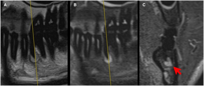
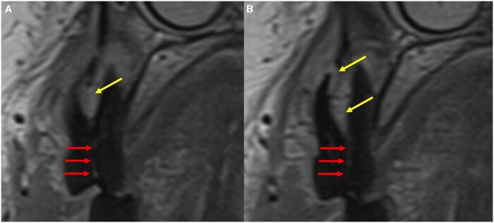
The needed information for the diagnosis of endodontic diseases is feasible using ddMRI. As presented in the selected cases (Figures 9 and 10), the images allow for identifying the anatomic structures inside (eg, pulp chamber and canals) and outside (eg, the periapical tissues) the teeth.16 As the earlier signs of endodontic disease (ie, inflammation) are usually seen in the soft tissues, in the suggested ddMRI system images can be acquired with and without fat suppression techniques (ie, highlighting relative increases in the fluid contents of the tissue, Figure 9). The suggested system can add data supporting the clinical information suggestive of endodontic disease. These include extensive tooth crown destruction by caries lesions and root fractures, often connected with apical periodontitis (Figure 10).
Figure 9.
ddMRI (2D acquisitions) of a left mandibular first molar that has been endodontically treated. Sagittal images were acquired without (A) and with (B) fat suppression. The hyperintense signal in the periapical region suggests inflammatory changes. No artefacts due to the gutta percha used for endodontic treatment were seen in the images. The coronal image (C, defined based on the yellow line visible in A and B), also acquired with fat suppression, highlights the extension of the hyperintense area (red arrow), confirming that this tissue has an altered fluid content, that can range from a simple oedema to a cyst or granuloma. ddMRI = dental-dedicated MRI.
Figure 10.
Consecutive ddMRI sagittal sections of a right maxillary premolar (2D acquisitions). The mild hyperintense area in the periapical region suggests apical inflammation (yellow arrows). The images also suggest the presence of a vertical root fracture (red arrows). ddMRI = dental-dedicated MRI.
Periodontal assessment
The suggested ddMRI system is a feasible imaging modality to depict altered marginal bone levels and assess its stability for treatment monitoring. It can also show more severe alterations, such as furcation involvement (ie, the loss of support bone in the area between the roots). By suggesting the presence of inflammation in the periodontal tissues (ie, depicting fluidic alterations),9 ddMR images might add significantly to the clinical diagnosis of periodontal diseases (Figure 11).
Figure 11.
ddMRI of a left maxillary first molar (2D acquisitions). Sagittal images without (A) and with (C) fat suppression and coronal image (B) without fat suppression. The yellow line visible in (B) (coronal plane) defines the sagittal plane presented in (A) and (C). In (A), the marginal bone level between the mesiofacial and palatinal roots is depicted (green arrows), and the presence of a furcation involvement is confirmed in the coronal image of the same area (yellow arrows in B). In (C), the hyperintense spot is suggestive of a relative increase in the fluid content within the soft tissue between the roots (yellow arrows in C), that might indicate inflammation. There is visible thickening of the maxillary sinus membrane (red arrows in A and B). ddMRI = dental-dedicated MRI.
Planning the extraction of impacted mandibular third molars
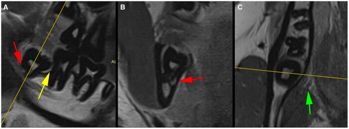
As this diagnostic task demands,17 the suggested ddMRI system offers information about the anatomy and shape of the tooth and its roots, the placement of the tooth in the mandible and its relationship with the mandibular canal (and the IAN), and possible interactions with the mandibular second molar, such as the presence of significant bone loss between the second and the third molars. In addition to depicting the tooth anatomy, as is already the case in panoramic and CBCT images, ddMRI can also be used to portray the lingual nerve, which typically runs near the lingual bony wall adjacent to the roots of a mandibular third molar (Figure 12).
Figure 12.
ddMRI of a right mandibular third molar (2D acquisitions). The yellow lines visible in (A) (sagittal plane) and (C) (axial plane) define the coronal plane (B). The images suggest an intimate relation between the tooth’s roots and the mandibular canal (red arrows in A and B) and the absence of bony separation between the root and the canal. Bone loss exceeding 50% of the second molar’s distal root length is visible (A, yellow arrow), and no signs of external root resorption are present. The lingual nerve is seen with a safe distance to the lingual bone wall surrounding the semiimpacted molar (green arrow in C). ddMRI = dental-dedicated MRI.
Discussion
The present technical report suggests a dental-dedicated approach to obtain detailed diagnostic images of dentomaxillofacial structures, namely ddMRI. This novel variant of MRI, is a radiation-free and noninvasive imaging modality that can potentially become preferred for some diagnostic tasks in dentistry. MRI has been used to display the dentomaxillofacial tissues across various indications and specialities in dentistry.5 However, this was done with the standard MRI setups used in dentistry (ie, not dental-dedicated). All dental MRI-based investigations have been performed at clinically established field strengths (eg, 1.5 or 3 T). ddMRI is innovative by suggesting the images can be acquired at lower field strength (0.55 T), possibly at a dental clinic or dentomaxillofacial diagnostic imaging centre. The images can be interpreted by a trained dentist or specialist in dentomaxillofacial radiology since the FOV is limited to the dentists’ area of expertise, and the brain is omitted from the images. In other words, ddMRI suggests a setup enabling MRI to be solely dependent on dentists.
Technical aspects
Specific criteria must be met to make MRI more feasible in dentistry. Among these, enabling the scanner to be closer to the dental practices (ie, reduction of footprint and installation requirements) may be the most relevant. This is achieved by using a 0.55-T scanner. Maintenance costs must be considered, and a closed, quench pipe-free system is a plausible alternative to reduce the technical demands of running an MRI system. The option for a lower field strength demanded other parameters (eg, the RF coil and the pulse sequences) to be developed, ensuring adequate diagnostic image quality at clinically plausible acquisition times (ie, pulse sequences of 3 min or less). From the previous literature, long acquisition times (eg, 7 min5) are typical when MRI fulfils dentistry-oriented tasks, interfering with patient comfort and leading to higher probabilities of motion artefacts in the images.
Over the past decades, there has been a trend towards higher field strengths (1.5 T and beyond).12 Low-field MRI is typically associated with noisier images, mainly because the MRI signal increases with the main magnetic field strength.18 However, the concept of direct signal-to-noise (SNR) dependence on magnetic field strength has since been reconsidered.12 The static (ie, main) magnetic field strength alone does not determine the image SNR, and advances in MR software (eg, pulse sequences and image reconstruction methods) and hardware (eg, dedicated RF coils) have been shown to play an essential role in enhancing image quality.12
An essential element of the suggested ddMRI system is the adaptation of pulse sequences. This included using image acquisition and reconstruction techniques that combine data under-sampling (eg, parallel imaging) with iterative reconstruction, such as CS and deep learning-based reconstruction techniques.11,13,14 These allowed to reduce overall scan duration while maintaining an adequate SNR. Basic physical property-related parameters in the pulse sequences were tailored to provide shorter scanning times and enhance diagnostic image quality. Among those, the T1 relaxation, one of the primary sources of image contrast in MRI, decreases with decreasing field strength, with the result that the repetition time, that is, the time between successive excitation pulses, can be reduced.19 This implies shorter scan times. Also, the magnetic susceptibility differences between tissues within the area of interest decrease with decreasing field strength.12 In brief, this means less signal degradation is observed at lower field strengths at tissue boundaries, such as those arising from the air in the sinuses and the Schneiderian membrane, or in the presence of metal. Finally, the receiver bandwidth in MRI is directly related to SNR. A smaller bandwidth improves the SNR but means longer scan times. A larger bandwidth allows faster imaging but increases noise. While the bandwidth is usually increased at high field strengths to allow for fast signal detection before decay, and to minimize the so-called chemical shift artefacts (eg, that occur at the boundaries between fatty and nonfatty tissues), these artefacts are less of a challenge at lower field strengths, allowing the selection of lower bandwidths without compromising image quality.12
Another critical technical feature was the use of a dental RF surface coil. The RF coil is an essential component in MR imaging and must be sensitive enough to detect the weak RF signals emitted after the tissues are magnetized through induction.20 The coil elements were adjusted to provide the highest sensitivity for the dentomaxillofacial region. In the case of ddMRI, this also adds the advantage of providing a FOV suitable for the dentist’s expertise. The RF coil design provided patient comfort and compatibility. The literature suggests that using specific surface coils for dental imaging has helped achieve high image resolution within acceptable acquisition times.5,21 Other approaches should be considered during coil development, such as placing RF coils within the mouth (ie, intraoral coils). The intraoral approach has been suggested in the literature,22–25 but has not been used widely.
One of the most challenging issues within MR imaging is the presence of artefacts in the images. Both the hardware and the software-related features in ddMRI play favourably towards the reduction of image artefacts. It is well documented that higher field strengths also result in more pronounced image artefacts, particularly in exogenous materials like implants or other restorations.10 This is related to the susceptibility effect, which linearly scales with the main magnetic field. In summary, the susceptibility artefacts in MRI originate from differences in the magnetic properties of different neighbouring tissue types and materials that lead to a local signal disturbance at respective interfaces (eg, soft tissue and air interfaces or in the proximity of paramagnetic materials).12 The literature suggests that paramagnetic metal-containing materials, such as those used in dental implants and prostheses, orthodontics, and restorative dentistry, result in substantially minor image artefacts than those observed at high field strength.10 Based on our limited experience, the metal artefacts visualized in the images were localized and therefore not of major diagnostic relevance. Also, the issue of patient motion artefacts must be considered.5 For example, upper airway assessment during orthodontic planning is often performed in younger patients, who are more prone to movement.26 Possible motion artefacts can interfere with image quality and the accuracy of the assessment. However, it is expected that the shorter acquisition times achieved by ddMRI, together with the surface coil design, will help reduce the prevalence of patient movement. Further studies within this field are needed to define the impact of susceptibility and patient motion artefacts for the diverse dentomaxillofacial-related tasks.
Usability aspects
Besides tailoring hardware components towards a smaller footprint, a ddMRI system must be handled by dental professionals (eg, dentists and dental assistants must be able to operate it). This implies that an intuitive ease-of-use approach and a “CBCT-like” patient and diagnostic workflow must be developed.10 The suggested image acquisition protocols (ie, the pulse sequences) permit emphasizing image contrasts that best fit the dentomaxillofacial area and diagnostic tasks. The reduced scan times (3 min or less for each pulse sequence, allowing the “in-room” time to be shorter than 20 min), minor susceptibility to artefacts, and the patient-friendly setup provided by a larger bore and dedicated RF surface coil are all part of the solution. Another key feature enabling dentists and dental assistants to use the suggested approach is the possibility of using small, targeted FOVs that only present those tissues that the dentists and dentomaxillofacial radiology specialists can report on. The proposed ddMRI system provides an anatomical coverage fit for dentistry, as it exists for CBCT imaging.
Reaching a spatial resolution acceptable to dentistry’s most common diagnostic tasks is also relevant, allowing the anatomical depiction of the hard and soft tissues within the jaws, including muscles, significant nerves, dental pulp, and, obviously, the teeth and bones.6,8 This feature is also provided by the in-plane spatial resolution of 0.2 mm (for the 2D pulse sequences) and 0.4 mm for 3D isotropic volumes, which aligns with what was previously achieved using higher field setups.5 Also, the pulse sequences must allow for differentiating between healthy and pathological tissues, but in a simple manner. Pulse sequences to characterize the inner bone structure using fat suppression approaches are an essential method to improve the differentiation between healthy and pathological tissues.27 Up to now, the use of a dual approach (eg, the identical pulse sequences with and without fat suppression) showed to be feasible for the commonly performed diagnoses in dentistry.
There is still much room to improve the ddMRI system introduced in this work in terms of its usability for dental professionals. In this sense, the workflow can be further optimized by offering an interface that is fully dedicated to dentistry, with improved image quality robustness possibilities (eg, motion artefact correction and metal artefact reduction), specific pulse sequence development (eg, targeting better visualization of hard tissues,28 dynamic imaging of TMJ range of motion and masticatory function,29 and even blood oxygenation level-dependent (BOLD) imaging that may allow targeting the diagnosis of pulp vitality without exogenous contrast agents30), as well as automated slice positioning/FOV placement, based on AI systems to assist with the task using the information from the scout images. Considering approximately the same acquisition time, the tested 3D pulse sequences provided lower spatial resolution than the 2D sequences, allowing for development if high-resolution, isotropic volumes are to be used (eg, as currently offered by CBCT imaging).
Diagnostic aspects
The presented cases suggest the ddMRI system as a feasible diagnostic modality in dentistry. For orthodontic planning, the literature suggests the equivalence of MRI and CBCT for cephalometry at higher field strengths.5 One can speculate the same will be valid for ddMRI, as image resolution is the critical parameter for that equivalence.5 For orthodontics, and considering the usual need for multiple images over time (ie, follow-up), the key added value for ddMRI is the possibility of providing “minimally invasive imaging” (ie, without the associated risks of radiation exposure). A particularly beneficial advantage when imaging young individuals who require repetitive imaging.7
Most diseases and relevant anatomic structures within the dentomaxillofacial area present major soft tissue components. However, these are not visible in the traditional diagnostic modalities used in dentistry.6,8,9 This is the case for the diagnosis of TMJ disorders.31 Therefore, MRI is already considered the gold standard imaging modality for diagnosing TMJ disorders.32 However, this evidence is based on the use of a scanner operating at 1.5 and 3 T, and must be further validated for 0.55 T. Preliminary data suggests no significant differences for the diagnosis of the TMJ area at 0.55 and 1.5 T.33,34 It must be emphasized, however, that the impact of MRI-based findings altering the course of the treatment of TMJ disorders is still under investigation.35
The proposed ddMRI system can also be speculatively used for diagnosing bone loss and inflammatory changes associated with endodontic and periodontal diseases. Inflammation in bony areas leads to free water accumulation in the extracellular space,9 which can be visualized with MRI, allowing for the detection of early changes before significant bone loss.6,8,36–38 A relevant added value of MRI is the depiction of osseous oedema, which results from the bone’s inflammatory process and is crucial for accurately diagnosing periodontal and periapical diseases.9 Most importantly, this is achieved without using exogenous contrast agents, which are not ideal within a dental-dedicated setup. However, it must be kept in mind that the accuracy of ddMRI in diagnosing periodontal and periapical disease is yet to be defined in more extensive clinical trials.5 Also relevant to mention, in the current study these diagnostic tasks were approached in a “targeted” manner (ie, small FOV). Future development should also investigate the possibility for “screening” bone loss and inflammatory changes associated with endodontic and periodontal diseases using a single, large FOV acquisition (ie, sequence).
Information about the vitality status of teeth is not available in ionizing radiation-based imaging modalities.6 The literature suggests high MRI signal intensity correlates with a perfused, vital pulp. In contrast, no signal is suggested to be associated with pulp necrosis or root-filled teeth.5 The same is valid for the suggested ddMRI system. The currently explored contrasts (ie, pulse sequences) of ddMRI are not yet compatible with diagnosing caries lesions. However, ddMRI can complement routine clinical and radiographic imaging screening for inflammatory processes, which could ultimately be related to a carious lesion.
Regarding the planning of the extraction of impacted molars, the suggested system differs from what was previously stated in the literature5 by suggesting that smaller FOVs provide sufficient diagnostic information. Even though no clinical trial yet exists comparing the diagnostic accuracy of MRI or ddMRI and CBCT when planning the extraction of impacted teeth, MRI is considered suitable.5 One can speculate that MRI might be superior for this specific task, as the traditional radiographic imaging modalities cannot depict the nerve directly and are limited to the location of the mandibular canal.17 Also, MRI may be used to investigate any intimate proximity of the lingual nerve with the lingual cortical bone, thus improving the surgeon’s presurgical information.
Educational aspects
Dentists are likely to adapt to the suggested system, as there is strong evidence of technology adaption in cases of added clinical value to the dentomaxillofacial diagnosis.2 ddMRI positions dentists to indicate, perform, and diagnose the images, but requires novel educational concepts for dental professionals, as it happened when CBCT was introduced.1
Educating dentists and dental assistants to work with ddMRI involves theoretical knowledge, practical training, and hands-on experience. The theoretical knowledge must provide a comprehensive understanding of the basic principles of MRI, including the physics behind image acquisition and how to select pulse sequences. Also, the anatomic and pathological interpretation of the structures as visualized on ddMRI must be explained. Practical training focusing on both dentists and dental assistants acquiring images must cover the safety aspects and provide hands-on ddMRI acquisition, focusing on proper patient positioning and RF coil adjustment. The equipment supplier could offer this part of the training, as it occurs for CBCT in some countries.39 Dentists must be trained regarding image reconstruction (ie, postprocessing techniques), learning to extract the needed diagnostic information to interpret ddMRI. Practical sessions where dentists could review and interpret images under the supervision of experienced specialists will be helpful at this stage. Future research can also explore educational concepts and didactic opportunities to incorporate ddMRI into the clinical practice of dentists.
Conclusion
The suggested ddMRI system is a feasible alternative to overcome some of the barriers preventing the breakthrough of MRI in dentistry, using a low-field scanner, a dedicated RF coil, and tailored pulse sequences. By incorporating soft tissue image-based diagnosis to dentists, ddMRI may facilitate early disease detection and preventive screening at a larger scale. There is potential for interdisciplinary research, as the diagnostic accuracy of the suggested system for the diverse possible indications is yet to be defined.
Contributor Information
Andreas Greiser, Siemens Healthcare GmbH, Erlangen, 91052, Germany.
Jennifer Christensen, Section for Oral Radiology and Endodontics, Department of Dentistry and Oral Health, Aarhus University, Aarhus, 8000, Denmark.
João M C S Fuglsig, Section for Oral Radiology and Endodontics, Department of Dentistry and Oral Health, Aarhus University, Aarhus, 8000, Denmark.
Katrine M Johannsen, Section for Oral Radiology and Endodontics, Department of Dentistry and Oral Health, Aarhus University, Aarhus, 8000, Denmark.
Donald R Nixdorf, Division of TMD & Orofacial Pain, School of Dentistry, University of Minnesota Twin Cities, MN, 55455, United States; Department of Radiology, Medical School, University of Minnesota Twin Cities, MN, 55455, United States.
Kim Burzan, Sirona Dental Systems GmbH, Bensheim, 64625, Germany.
Lars Lauer, Siemens Healthcare GmbH, Erlangen, 91052, Germany.
Gunnar Krueger, Siemens Healthcare GmbH, Erlangen, 91052, Germany.
Carmel Hayes, Siemens Healthcare GmbH, Erlangen, 91052, Germany.
Karen Kettless, Siemens Healthcare GmbH, Erlangen, 91052, Germany.
Johannes Ulrici, Sirona Dental Systems GmbH, Bensheim, 64625, Germany.
Rubens Spin-Neto, Section for Oral Radiology and Endodontics, Department of Dentistry and Oral Health, Aarhus University, Aarhus, 8000, Denmark.
Funding
None declared.
Conflicts of interest
A. Greiser, L. Lauer, G. Krueger, C. Hayes, and K. Kettless work for Siemens Healthcare GmbH, while J. Ulrici and K. Burzan work for Sirona Dental Systems GmbH, which are the companies developing the ddMRI machine tested in the present study.
References
- 1. Guidelines on CBCT for Dental and Maxillofacial Radiology. SEDENTEXCT Project - Radiation protection no 172; 2012.
- 2. Jacobs R, Salmon B, Codari M, Hassan B, Bornstein MM.. Cone beam computed tomography in implant dentistry: recommendations for clinical use. BMC Oral Health. 2018;18(1):88. 10.1186/s12903-018-0523-5 [DOI] [PMC free article] [PubMed] [Google Scholar]
- 3. Chackartchi T, Romanos GE, Parkanyi L, Schwarz F, Sculean A.. Reducing errors in guided implant surgery to optimize treatment outcomes. Periodontol 2000. 2022;88(1):64-72. 10.1111/prd.12411 [DOI] [PubMed] [Google Scholar]
- 4. Patel S. New dimensions in endodontic imaging: part 2. Cone beam computed tomography. Int Endod J. 2009;42(6):463-475. 10.1111/j.1365-2591.2008.01531.x [DOI] [PubMed] [Google Scholar]
- 5. Flugge T, Gross C, Ludwig U, et al. Dental MRI-only a future vision or standard of care? A literature review on current indications and applications of MRI in dentistry. Dentomaxillofac Radiol. 2023;52(4):20220333. 10.1259/dmfr.20220333 [DOI] [PMC free article] [PubMed] [Google Scholar]
- 6. Idiyatullin D, Corum C, Moeller S, Prasad HS, Garwood M, Nixdorf DR.. Dental magnetic resonance imaging: making the invisible visible. J Endod. 2011;37(6):745-752. 10.1016/j.joen.2011.02.022 [DOI] [PMC free article] [PubMed] [Google Scholar]
- 7. De Grauwe A, Ayaz I, Shujaat S, et al. CBCT in orthodontics: a systematic review on justification of CBCT in a paediatric population prior to orthodontic treatment. Eur J Orthod. 2019;41(4):381-389. 10.1093/ejo/cjy066 [DOI] [PMC free article] [PubMed] [Google Scholar]
- 8. Hovener JB, Zwick S, Leupold J, et al. Dental MRI: imaging of soft and solid components without ionizing radiation. J Magn Reson Imaging. 2012;36(4):841-846. 10.1002/jmri.23712 [DOI] [PubMed] [Google Scholar]
- 9. Probst M, Burian E, Robl T, et al. Magnetic resonance imaging as a diagnostic tool for periodontal disease: a prospective study with correlation to standard clinical findings-Is there added value? J Clin Periodontol. 2021;48(7):929-948. 10.1111/jcpe.13458 [DOI] [PubMed] [Google Scholar]
- 10. Demirturk Kocasarac H, Geha H, Gaalaas LR, Nixdorf DR.. MRI for dental applications. Dent Clin North Am. 2018;62(3):467-480. 10.1016/j.cden.2018.03.006 [DOI] [PubMed] [Google Scholar]
- 11. Hamilton J, Franson D, Seiberlich N.. Recent advances in parallel imaging for MRI. Prog Nucl Magn Reson Spectrosc. 2017;101:71-95. 10.1016/j.pnmrs.2017.04.002 [DOI] [PMC free article] [PubMed] [Google Scholar]
- 12. Hori M, Hagiwara A, Goto M, Wada A, Aoki S.. Low-field magnetic resonance imaging: its history and renaissance. Invest Radiol. 2021;56(11):669-679. 10.1097/RLI.0000000000000810 [DOI] [PMC free article] [PubMed] [Google Scholar]
- 13. Fritz J, Raithel E, Thawait GK, Gilson W, Papp DF.. Six-fold acceleration of high-spatial resolution 3D SPACE MRI of the knee through incoherent k-space undersampling and iterative reconstruction-first experience. Invest Radiol. 2016;51(6):400-409. 10.1097/RLI.0000000000000240 [DOI] [PubMed] [Google Scholar]
- 14. Herrmann J, Koerzdoerfer G, Nickel D, et al. Feasibility and implementation of a deep learning MR reconstruction for TSE sequences in musculoskeletal imaging. Diagnostics (Basel). 2021;11(8): 10.3390/diagnostics11081484 [DOI] [PMC free article] [PubMed] [Google Scholar]
- 15. Angeles-Han ST, Ringold S, Beukelman T, et al. 2019 American College of Rheumatology/Arthritis Foundation Guideline for the screening, monitoring, and treatment of juvenile idiopathic arthritis-associated uveitis. Arthritis Care Res (Hoboken). 2019;71(6):703-716. 10.1002/acr.23871 [DOI] [PMC free article] [PubMed] [Google Scholar]
- 16. Patel S, Brown J, Semper M, Abella F, Mannocci F.. European Society of Endodontology position statement: use of cone beam computed tomography in endodontics: European Society of Endodontology (ESE) developed by. Int Endod J. 2019;52(12):1675-1678. 10.1111/iej.13187 [DOI] [PubMed] [Google Scholar]
- 17. Matzen LH, Wenzel A.. Efficacy of CBCT for assessment of impacted mandibular third molars: a review—based on a hierarchical model of evidence. Dentomaxillofac Radiol. 2015;44(1):20140189. 10.1259/dmfr.20140189 [DOI] [PMC free article] [PubMed] [Google Scholar]
- 18. Hayashi N, Watanabe Y, Masumoto T, et al. Utilization of low-field MR scanners. Magn Reson Med Sci. 2004;3(1):27-38. 10.2463/mrms.3.27 [DOI] [PubMed] [Google Scholar]
- 19. Goldman M. Formal theory of spin—lattice relaxation. J Magn Reson. 2001;149(2):160-187. 10.1006/jmre.2000.2239 [DOI] [PubMed] [Google Scholar]
- 20. Gruber B, Froeling M, Leiner T, Klomp DWJ.. RF coils: a practical guide for nonphysicists. J Magn Reson Imaging. 2018;48(3):590-604. 10.1002/jmri.26187 [DOI] [PMC free article] [PubMed] [Google Scholar]
- 21. Prager M, Heiland S, Gareis D, Hilgenfeld T, Bendszus M, Gaudino C.. Dental MRI using a dedicated RF-coil at 3 Tesla. J Craniomaxillofac Surg. 2015;43(10):2175-2182. 10.1016/j.jcms.2015.10.011 [DOI] [PubMed] [Google Scholar]
- 22. Ozen AC, Idiyatullin D, Adriany G, et al. Design of an intraoral dipole antenna for dental applications. IEEE Trans Biomed Eng. 2021;68(8):2563-2573. 10.1109/TBME.2021.3055777 [DOI] [PMC free article] [PubMed] [Google Scholar]
- 23. Ludwig U, Eisenbeiss AK, Scheifele C, et al. Dental MRI using wireless intraoral coils. Sci Rep. 2016;6:23301. https://doi.org/10.1038/srep23301 [DOI] [PMC free article] [PubMed] [Google Scholar]
- 24. Idiyatullin D, Corum CA, Nixdorf DR, Garwood M.. Intraoral approach for imaging teeth using the transverse B1 field components of an occlusally oriented loop coil. Magn Reson Med. 2014;72(1):160-165. 10.1002/mrm.24893 [DOI] [PMC free article] [PubMed] [Google Scholar]
- 25. Tymofiyeva O, Boldt J, Rottner K, Schmid F, Richter EJ, Jakob PM.. High-resolution 3D magnetic resonance imaging and quantification of carious lesions and dental pulp in vivo. MAGMA. 2009;22(6):365-374. 10.1007/s10334-009-0188-9 [DOI] [PubMed] [Google Scholar]
- 26. Spin-Neto R, Hauge Matzen L, Hermann L, Fuglsig J, Wenzel A.. Head motion and perception of discomfort by young children during simulated CBCT examinations. Dentomaxillofac Radiol. 2021;50(3):20200445. 10.1259/dmfr.20200445 [DOI] [PMC free article] [PubMed] [Google Scholar]
- 27. Delfaut EM, Beltran J, Johnson G, Rousseau J, Marchandise X, Cotten A.. Fat suppression in MR imaging: techniques and pitfalls. Radiographics. 1999;19(2):373-382. 10.1148/radiographics.19.2.g99mr03373 [DOI] [PubMed] [Google Scholar]
- 28. Bracher AK, Hofmann C, Bornstedt A, et al. Ultrashort echo time (UTE) MRI for the assessment of caries lesions. Dentomaxillofac Radiol. 2013;42(6):20120321. 10.1259/dmfr.20120321 [DOI] [PMC free article] [PubMed] [Google Scholar]
- 29. Perry JL, Gilbert IR, Xing F, et al. Preliminary development of an MRI atlas for application to cleft care: findings and future recommendations. Cleft Palate Craniofac J. 2023;10556656231183385. 10.1177/10556656231183385 [DOI] [PubMed] [Google Scholar]
- 30. Di Nardo D, Gambarini G, Capuani S, Testarelli L.. Nuclear magnetic resonance imaging in endodontics: a review. J Endod. 2018;44(4):536-542. 10.1016/j.joen.2018.01.001 [DOI] [PubMed] [Google Scholar]
- 31. Larheim TA, Abrahamsson AK, Kristensen M, Arvidsson LZ.. Temporomandibular joint diagnostics using CBCT. Dentomaxillofac Radiol. 2015;44(1):20140235. 10.1259/dmfr.20140235 [DOI] [PMC free article] [PubMed] [Google Scholar]
- 32. Ahmad M, Hollender L, Anderson Q, et al. Research diagnostic criteria for temporomandibular disorders (RDC/TMD): development of image analysis criteria and examiner reliability for image analysis. Oral Surg Oral Med Oral Pathol Oral Radiol Endod. 2009;107(6):844-860. 10.1016/j.tripleo.2009.02.023 [DOI] [PMC free article] [PubMed] [Google Scholar]
- 33. Nixdorf DR, Greiser A, Hayes C, et al. Qualitative comparison between 0.55T and 1.5T temporomandibular joint MRIs. Abstracts of the 2023 IADR/LAR General Session, 2023. https://iadr.abstractarchives.com/abstract/23iags-3895869/qualitative-comparison-between-055t-and-15t-temporomandibular-joint-mris [Google Scholar]
- 34. Kopp M, Wiesmueller M, Buchbender M, et al. MRI of temporomandibular joint disorders: a comparative study of 0.55 T and 1.5 T MRI. Invest Radiol. 2023. EPub ahead of print. 10.1097/RLI.0000000000001008 [DOI] [PMC free article] [PubMed] [Google Scholar]
- 35. Eriksen ES, Hellem S, Skartveit L, et al. Temporomandibular joint pain and associated magnetic resonance findings: a retrospective study with a control group. Acta Radiol Open. 2020;9(9):2058460120938738. 10.1177/2058460120938738 [DOI] [PMC free article] [PubMed] [Google Scholar]
- 36. Juerchott A, Pfefferle T, Flechtenmacher C, et al. Differentiation of periapical granulomas and cysts by using dental MRI: a pilot study. Int J Oral Sci. 2018;10(2):17. 10.1038/s41368-018-0017-y [DOI] [PMC free article] [PubMed] [Google Scholar]
- 37. Juerchott A, Sohani M, Schwindling FS, et al. In vivo accuracy of dental magnetic resonance imaging in assessing maxillary molar furcation involvement: a feasibility study in humans. J Clin Periodontol. 2020;47(7):809-815. 10.1111/jcpe.13299 [DOI] [PubMed] [Google Scholar]
- 38. Juerchott A, Sohani M, Schwindling FS, et al. Comparison of non-contrast-enhanced dental magnetic resonance imaging and cone-beam computed tomography in assessing the horizontal and vertical components of furcation defects in maxillary molars: an in vivo feasibility study. J Clin Periodontol. 2020;47(12):1485-1495. 10.1111/jcpe.13374 [DOI] [PubMed] [Google Scholar]
- 39. Brown J, Jacobs R, Levring Jaghagen E, et al. ; European Academy of DentoMaxilloFacial Radiology. Basic training requirements for the use of dental CBCT by dentists: a position paper prepared by the European Academy of DentoMaxilloFacial Radiology. Dentomaxillofac Radiol. 2014;43(1):20130291. 10.1259/dmfr.20130291 [DOI] [PMC free article] [PubMed] [Google Scholar]


