Abstract
BACKGROUND
Silent magnetic resonance angiography (MRA) mitigates metal artifacts, facilitating clear visualization of neck remnants after stent and coil embolization of cerebral aneurysms. This study aims to scrutinize hemodynamics at the neck remnant by employing silent MRA and computational fluid dynamics.
OBSERVATIONS
The authors longitudinally tracked images of a partially thrombosed anterior communicating artery aneurysm’s neck remnant, which had been treated with stent-assisted coil embolization, using silent MRA over a decade. Computational fluid dynamics delineated the neck remnant’s reduction process, evaluating hemodynamic parameters such as flow rate, wall shear stress magnitude and vector, and streamlines. The neck remnant exhibited diminishing surface area, volume, neck size, dome depth, and aspect ratio. Its reduction correlated with a decline in the flow rate ratio of the remnant dome to the inflow parent artery. Analysis delineated regions within the contracting neck remnant characterized by consistently low average wall shear stress magnitude and variation, accompanied by notable variations in wall shear stress vector directionality.
LESSONS
Evaluation of neck remnants after stent-coil embolization is possible through silent MRA and computational fluid dynamics. Predicting the neck remnant reduction may be achievable through hemodynamic parameter analysis.
Keywords: computational fluid dynamics, neck remnant, magnetic resonance image, silent magnetic resonance angiography, stent and coil embolization, wall shear stress
ABBREVIATIONS: 3D = 3-dimensional, CFD = computational fluid dynamics, DSA = digital subtraction angiography, MRA = magnetic resonance angiography, TOF-MRA = time-of-flight magnetic resonance angiography, WSS = wall shear stress, WSSm = magnitude of wall shear stress, WSSv = vector of wall shear stress
After stent and coil embolization of cerebral aneurysms, visualization of the neck remnant is often inadequate with time-of-flight magnetic resonance angiography (TOF-MRA) because of metal artifacts.1 However, silent MRA reduces these artifacts, enabling relatively good visualization of the neck remnant. Enlargement of the neck remnant poses a risk of rupture and can necessitate retreatment.2 Although pathological and experimental studies have reported on the neck remnant after coil embolization,3 details regarding the reduction or enlargement of a neck remnant in clinical cases remain unclear. In this study, we longitudinally tracked images of the neck remnant of a partially thrombosed anterior communicating artery aneurysm treated with stent-assisted coil embolization using silent MRA over a 10-year period. The neck remnant reduction process was analyzed using computational fluid dynamics (CFD), examining hemodynamic parameters such as pressure drop (mm Hg), flow rate (ml/min), flow rate ratio (inflow parent artery to remnant aneurysmal dome), magnitude of wall shear stress (WSSm; Pa), vector of WSS (WSSv), and streamlines.
Illustrative Case
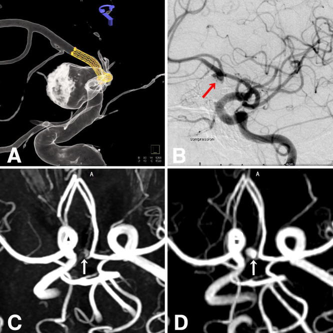
A 62-year-old woman with limb-girdle muscular dystrophy since the age of 43 presented with headaches and was found to have an anterior communicating artery aneurysm on examination. Computed tomography angiography and digital subtraction angiography (DSA) revealed a 5.4 × 14.7 × 14–mm saccular aneurysm with a neck in the right A1–2 segment, accompanied by intraluminal thrombus on the right side (Fig. 1). Stent-assisted coiling was performed using an Enterprise stent (4.5/28) in conjunction with 12 coils (Hydrocoil 4/10, Hydrosoft 5/15, Axium 4/12, Target Ultra 4/8; Fig. 2). A neck remnant was evident on DSA 1 year after treatment. Subsequent TOF-MRA 5 years later revealed a neck remnant, albeit with poor imaging quality. In contrast, simultaneous silent MRA conducted on a 3-T unit (Signa Pioneer, GE Healthcare) revealed a well-defined neck remnant. Follow-up silent MRA was repeated at the 6th, 8th, and 10th years, allowing tracking of the morphology of the neck remnant.
FIG. 1.

Anterior communicating artery aneurysm before treatment. Computed tomography (CT) (A), contrast-enhanced CT (B), and DSA anteroposterior (C) and right lateral (D) projections, showing a 5.4 × 14.7 × 14–mm saccular aneurysm with a neck in the right A1–2 segment, accompanied by intraluminal thrombus on the right side. Arrows indicate the aneurysm.
FIG. 2.

Stent-assisted coil treatment (A) was planned using an Enterprise stent along with coils. DSA 1 year after treatment (B) showing the presence of a neck remnant. TOF-MRA 5 years later (C) also shows a neck remnant, albeit with poor imaging quality. Simultaneous silent MRA (D) reveals a well-depicted neck remnant. Arrows indicate the neck remnant.
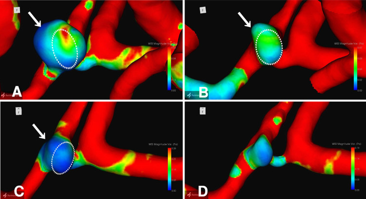
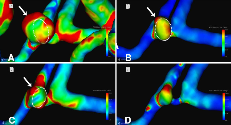
The neck remnant was analyzed using a commercial CFD package (Hemoscope version 1.4, EBM Corp.), as described elsewhere.4 The morphology of the neck remnant, including surface area, volume, neck size, dome length, and aspect ratio, was quantified (Table 1). Hemodynamic parameters, such as pressure drop (mm Hg), flow rate (ml/min), WSSm (Pa), WSSv, and streamlines, were evaluated. The analysis revealed a gradual decrease in the morphology of the neck remnant in terms of surface area, volume, neck size, dome length, and aspect ratio. Hemodynamic parameters indicated a decline in the flow rate ratio of the remnant dome to the inflow parent artery, coupled with an increase in the dispersion and coarseness of streamlines entering the remnant over time. Furthermore, 3-dimensional (3D) images of the neck remnant showed reductions in regions with small WSSm-average and WSSm-variation (Fig. 3) in particular, as well as areas with unstable WSSv-average and large WSSv-variation (Fig. 4).
TABLE 1.
Hemodynamic parameters after stent-coil embolization, analyzed using silent MRA and CFD
| Region | Hemodynamics |
Aneurysm |
Flow Rate (An/A1) Ratio | Aneurysm WSS Ratio | Pressure Drop Ratio | ||||||
|---|---|---|---|---|---|---|---|---|---|---|---|
| Flow Rate (ml/min) | Mean WSS (Pa) | Pressure Drop (mm Hg) | Surface Area (mm2) | Vol (mm3) | Neck Size (mm) | Depth (mm) | Aspect Ratio | ||||
| 5th yr |
|
|
|
|
|
|
|
|
|
|
|
| Rt A1 |
59.91 |
3.65 |
12.66 |
|
|
|
|
|
|
|
|
| Rt A2 |
47.98 |
2.57 |
5.96 |
|
|
|
|
|
|
|
|
| Lt A1 |
74.30 |
1.85 |
4.94 |
|
|
|
|
|
|
|
|
| Lt A1 |
74.33 |
1.24 |
3.09 |
|
|
|
|
|
|
|
|
| Aneurysm |
12.15 |
0.22 |
3.93 |
84.47 |
93.53 |
5.22 |
4.11 |
0.79 |
1.00 |
1.00 |
1.00 |
| 6th yr |
|
|
|
|
|
|
|
|
|
|
|
| Rt A1 |
36.23 |
1.32 |
4.45 |
|
|
|
|
|
|
|
|
| Rt A2 |
55.33 |
3.32 |
8.39 |
|
|
|
|
|
|
|
|
| Lt A1 |
133.21 |
2.85 |
8.93 |
|
|
|
|
|
|
|
|
| Lt A1 |
114.66 |
3.77 |
9.06 |
|
|
|
|
|
|
|
|
| Aneurysm |
5.27 |
0.17 |
1.26 |
47.67 |
39.21 |
4.40 |
3.09 |
0.70 |
0.43 |
0.77 |
0.32 |
| 8th yr |
|
|
|
|
|
|
|
|
|
|
|
| Rt A1 |
34.63 |
2.75 |
4.95 |
|
|
|
|
|
|
|
|
| Rt A2 |
30.09 |
2.89 |
3.99 |
|
|
|
|
|
|
|
|
| Lt A1 |
63.32 |
2.01 |
7.98 |
|
|
|
|
|
|
|
|
| Lt A1 |
67.87 |
3.30 |
3.91 |
|
|
|
|
|
|
|
|
| Aneurysm |
4.17 |
0.17 |
0.38 |
32.01 |
24.23 |
4.29 |
2.25 |
0.52 |
0.34 |
0.77 |
0.10 |
| 10th yr |
|
|
|
|
|
|
|
|
|
|
|
| Rt A1 |
33.68 |
2.78 |
4.26 |
|
|
|
|
|
|
|
|
| Rt A2 |
34.45 |
4.55 |
9.41 |
|
|
|
|
|
|
|
|
| Lt A1 |
54.32 |
1.89 |
6.40 |
|
|
|
|
|
|
|
|
| Lt A1 |
53.37 |
3.00 |
3.58 |
|
|
|
|
|
|
|
|
| Aneurysm | 3.52 | 0.33 | 1.22 | 22.09 | 13.31 | 3.45 | 2.15 | 0.42 | 0.29 | 1.52 | 0.31 |
FIG. 3.
3D images of WSSm-variation: 5 (A), 6 (B), 8 (C), and 10 (D) years after stent-coil embolization. Dotted circles indicate superimposed remnant morphology at the next examination. Arrows indicate localized sites of remnant shrinkage.
FIG. 4.
3D images of WSSv-variation: 5 (A), 6 (B), 8 (C), and 10 (D) years after stent-coil embolization. Dotted circles indicate superimposed remnant morphology at the next examination. Arrows indicate localized sites of remnant shrinkage.
Patient Informed Consent
The necessary patient informed consent was obtained in this study.
Discussion
After stent and coil embolization of cerebral aneurysms, the persistence of neck remnants is common and poses a risk of enlargement and rupture. Factors contributing to the presence of residual necks and coil compaction include aneurysm morphology, such as large size and neck width, as well as coil packing density.5 Postembolization, aneurysms are believed to be excluded from the parent vessel due to processes such as thrombus formation, active inflammation, and neoendothelialization occurring at the neck region.3
Numerous reports have investigated the hemodynamic factors associated with the growth and rupture of cerebral aneurysms using CFD and have been explored primarily in unruptured cerebral aneurysms.6–10 The genesis and progression of aneurysms are believed to be influenced by intraaneurysmal hemodynamics and wall strength. However, concerning the deformation of aneurysms such as blebs, there is a divergence between theories. One school of thought suggests the involvement of strong inflow jets and high WSS,6 whereas another proposes the involvement of low WSS and a high shear stress gradient,7 with no consistent consensus reached. Bleb formation, recognized as a risk factor for aneurysm rupture, has been attributed not only to intraluminal and wall factors but also to perianeurysmal contact with surrounding structures such as brain parenchyma and bony structures.4,10
Regarding neck remnants after coil embolization, there are limited reports available.11–14 Luo et al.11 observed 11 cases of neck remnants after coil embolization over a 2-year follow-up period. They reported that in 5 cases in which enlargement of the remnant was observed, the neck remnants showed high WSS and blood flow velocity at the neck, coinciding with the location where the remnant occurred. Sugiyama et al.12 investigated 57 cases of neck remnants after coil embolization of basilar tip aneurysms and found that the occurrence of neck remnants was influenced by the branching structure of the basilar artery, an increase in the flow rate ratio into the aneurysm and the basilar artery, and coil packing density of less than 30%.
However, there have been no reports on the hemodynamic factors associated with the shrinkage or disappearance of the aneurysm dome, bleb, and neck remnants. In this study, we investigated neck remnants following stent and coil embolization of partially thrombosed anterior communicating artery aneurysms using silent MRA. We analyzed the neck remnants using CFD and examined hemodynamic parameters related to shrinkage. The reduction in the flow rate ratio into the remnant aneurysm dome from the parent vessel was linked to the contraction of the neck remnants. Additionally, local factors contributing to neck remnant shrinkage tended to include regions characterized by small average WSSm and low WSSm-variation in particular, as well as areas with unstable average WSSv and notable large WSSv-variation. In WSSv, the directionality of WSS is indicated, and greater variation suggests instability in the hemodynamics within the neck remnant. Consequently, phenomena such as flow collision and stagnation are anticipated, promoting thrombosis and ultimately resulting in shrinkage of the neck remnant.
Observations
The evaluation of hemodynamics at the neck remnants after stent and coil embolization was feasible using CFD based on silent MRA. Hemodynamic characteristics, including decreased flow rate ratio into the neck remnant from the parent vessel and increased dispersion and coarseness of streamlines entering the remnant, correlated with neck remnant reduction. Regions exhibiting small WSSm and low WSSm-variation, as well as areas displaying large WSSv-variation, were observed in correlation with the localized area of neck remnant shrinkage. The prediction of neck remnant shrinkage was deemed achievable through CFD analysis using silent MRA.
Lessons
By analyzing hemodynamic parameters such as WSSm and WSSv using CFD based on silent MRA, it was possible to predict local sites associated with the shrinkage of neck remnants after stent and coil embolization. Although the hemodynamic parameters suggestive of neck remnant enlargement were inferred from the results of this study, further investigations with more case studies are awaited for detailed elucidation.
Acknowledgments
We thank Megumi Sasaki and Yudai Abe, radiological technicians, and Kana Murakami, laboratory technologist at Ryofukai Satoh Neurosurgical Hospital, for conducting the magnetic resonance examinations.
Author Contributions
Conception and design: Satoh. Acquisition of data: all authors. Analysis and interpretation of data: Satoh, Sugiu, Date. Drafting the article: Satoh. Critically revising the article: Satoh, Hiramatsu, Date. Reviewed submitted version of manuscript: Satoh, Sugiu, Hiramatsu, Date. Approved the final version of the manuscript on behalf of all authors: Satoh. Administrative/technical/material support: Satoh, Sugiu. Study supervision: Date.
References
- 1. Pierot L, Portefaix C, Gauvrit JY, Boulin A. Follow-up of coiled intracranial aneurysms: comparison of 3D time-of-flight MR angiography at 3T and 1.5T in a large prospective series. AJNR Am J Neuroradiol. 2012;33(11):2162–2166. doi: 10.3174/ajnr.A3124. [DOI] [PMC free article] [PubMed] [Google Scholar]
- 2. Satoh T, Hishikawa T, Hiramatsu M, Sugiu K, Date I. Visualization of aneurysmal neck and dome after coiling with 3D multifusion imaging of silent MRA and FSE-MR cisternography. AJNR Am J Neuroradiol. 2019;40(5):802–807. doi: 10.3174/ajnr.A6026. [DOI] [PMC free article] [PubMed] [Google Scholar]
- 3. Grüter BE, Wanderer S, Strange F, et al. Patterns of neointima formation after coil or stent treatment in a rat saccular sidewall aneurysm model. Stroke. 2021;52(3):1043–1052. doi: 10.1161/STROKEAHA.120.032255. [DOI] [PubMed] [Google Scholar]
- 4. Satoh T, Yagi T, Sawada Y, Sugiu K, Sato Y, Date I. Association of bleb formation with peri-aneurysmal contact in unruptured intracranial aneurysms. Sci Rep. 2022;12(1):6075. doi: 10.1038/s41598-022-10064-8. [DOI] [PMC free article] [PubMed] [Google Scholar]
- 5. Fujimura S, Takao H, Suzuki T, et al. A new combined parameter predicts re-treatment for coil-embolized aneurysms: a computational fluid dynamics multivariable analysis study. J Neurointerv Surg. 2018;10(8):791–796. doi: 10.1136/neurintsurg-2017-013433. [DOI] [PMC free article] [PubMed] [Google Scholar]
- 6. Cebral JR, Sheridan M, Putman CM. Hemodynamics and bleb formation in intracranial aneurysms. AJNR Am J Neuroradiol. 2010;31(2):304–310. doi: 10.3174/ajnr.A1819. [DOI] [PMC free article] [PubMed] [Google Scholar]
- 7. Shojima M, Nemoto S, Morita A, Oshima M, Watanabe E, Saito N. Role of shear stress in the blister formation of cerebral aneurysms. Neurosurgery. 2010;67(5):1268–1275. doi: 10.1227/NEU.0b013e3181f2f442. [DOI] [PubMed] [Google Scholar]
- 8. Frösen J, Cebral J, Robertson AM, Aoki T. Flow-induced, inflammation-mediated arterial wall remodeling in the formation and progression of intracranial aneurysms. Neurosurg Focus. 2019;47(1):E21. doi: 10.3171/2019.5.FOCUS19234. [DOI] [PMC free article] [PubMed] [Google Scholar]
- 9. Satoh T, Yasuhara T, Umakoshi M, et al. Trigeminal neuralgia caused by a persistent primitive trigeminal artery: preoperative three-dimensional multifusion imaging and computational fluid dynamics analysis. Illustrative case. J Neurosurg Case Lessons. 2023;5(19):CASE2381. doi: 10.3171/CASE2381. [DOI] [PMC free article] [PubMed] [Google Scholar]
- 10. Satoh T, Sato Y, Sawada Y. Peri-aneurysmal contact as a risk factor for aneurysmal rupture in unruptured intracranial aneurysms: an overview. Med Res Arch. 2024;12(2) [Google Scholar]
- 11. Luo B, Yang X, Wang S, et al. High shear stress and flow velocity in partially occluded aneurysms prone to recanalization. Stroke. 2011;42(3):745–753. doi: 10.1161/STROKEAHA.110.593517. [DOI] [PubMed] [Google Scholar]
- 12. Sugiyama S, Niizuma K, Sato K, et al. Blood flow into basilar tip aneurysms. A predictor for recanalization after coil embolization. Stroke. 2016;47(10):2541–2547. doi: 10.1161/STROKEAHA.116.013555. [DOI] [PubMed] [Google Scholar]
- 13. Umeda Y, Ishida F, Tsuji M, et al. Computational fluid dynamics (CFD) using porous media modeling predicts recurrence after coiling of cerebral aneurysms. PLoS One. 2017;12(12):e0190222. doi: 10.1371/journal.pone.0190222. [DOI] [PMC free article] [PubMed] [Google Scholar]
- 14. Suzuki T, Genkai N, Nomura T, Abe H. Assessing the hemodynamics in residual cavities of intracranial aneurysm after coil embolization with combined computational flow dynamics and silent magnetic resonance angiography. J Stroke Cerebrovasc Dis. 2020;29(12):105290. doi: 10.1016/j.jstrokecerebrovasdis.2020.105290. [DOI] [PubMed] [Google Scholar]


