

Abstract
An oxygen-rich and low NOx burner integrated with liquefied natural gas (LNG) was proposed to address unstable combustion and high NOx emissions from a 330 MW subcritical boiler under ultra-low load operation in China. To assess the effectiveness of the retrofit, Chemkin and Fluent softwares were utilized to construct a new NOx model and calculate NOx generation, based on the combustion of pulverized coal gas and LNG. Further, an eddy dissipation concept (EDC) model, which can reflect detailed chemical reactions, was applied to calculate gas-phase reactions in the furnace. The results showed that when performing the deep peak shaving after the retrofit, the combustion in the furnace was stable under 50% or more load, and NOx emission level at the furnace outlet was lower than 350 mg/m3 (6% O2 content, dry basis). Under 25% load, the oxygen-rich burner integrated with LNG was applied, and the pulverized coal flow entered the furnace in a state of high-intensity combustion, which effectively promoted the stability of combustion in the furnace. The reductive combustion state with reductive free radicals generated by LNG decomposition inhibited NOx formation. Consequently, NOx emissions from the furnace outlet decreased from 380 mg/m3 to 316 mg/m3.
Keywords: Boiler retrofit, Burner, LNG, Deep peak shaving, NOx emissions, Combustion, Numerical simulation
1. Introduction
Thermal power technology in China is constantly evolving. Currently, 300 MW thermal power generating units, especially units using lean coal, are facing tough competition and peak regulation [1], [2], [3]. Although several coal-fired generating units with larger capacity and higher efficiency parameters have been built, some 300 MW units are striving to meet flexible transformation requirements and achieve stable combustion under low load and low pollutant discharge to ensure economic viability [4], [5], [6], [7].
Several local and global studies have conducted experiments and numerical calculations to address problems faced by coal-fired boilers operating under low load. Research has indicated that the steady combustion effect can be improved moderately by reducing pulverized coal fineness, controlling the oxygen content in the furnace, and reasonably laying the protective combustion zone [8], [9]. When the boiler is operated at 500–800 MW load, the furnace temperature is relatively high, and a large excess air coefficient is adopted to help the coal powder burn out. However, when the peak load is as low as 300 MW, the oxygen at the outlet of the furnace must be controlled at approximately 3% to improve the combustion temperature in the furnace and achieve stable combustion. Tsumura et al. [10] conducted a single burner combustion test on a new burner with a flame stabilization ring and special air nozzle and achieved 50% minimum stable operating load of the burner (boiler operating load of 30–40%) and nitrogen oxide emissions below 200 mg/m3 (6% O2 content, dry basis). A field test conducted by Yang et al. [7] on a 330 MW lean coal boiler revealed that the NOx concentration in the inlet section of selective catalytic reduction (SCR) was relatively stable (<600 mg/m3) when the boiler was operated under a stable load; however, NOx concentration in the inlet section of the SCR was high (>650 mg/m3) when the boiler was operated under variable load and low load.
Domestic and foreign studies on low NOx and deep peak regulation suggest that solutions for the low NOx transformation of coal-fired boilers available currently are relatively mature [11], [12]. However, stable combustion and pollutant emission control, which comply with national environmental protection standards under deep peak regulation, have to be identified urgently [13], [14]. Currently, thermal power units in China are facing multiple obstacles such as poor coal quality, coal consumption reduction, peak depth adjustment, and ultra-low pollutant discharge standards. In this light, China Guodian Corporation conducted a research on unit number 2 of their Shizuishan power plant, and proposed a set of transformation plans constituting oxygen-rich and low NOx burners integrated with LNG to resolve the problems currently faced by 330 MW boilers.
The study used Chemkin software to calculate the NOx generation and reduction process of LNG-mixed coal gas flow during combustion to explore the reaction mechanism and verify the feasibility of the scheme. Additionally, the reactions were selected and simplified based on the combustion of various components and feasibility of Fluent simulation, and a new gas-solid mixed NOx model was constructed. Then, an eddy dissipation concept (EDC) was employed to calculate the gas reaction in the furnace. The NOx model constructed was applied to Fluent software to simulate the combustion performance and NOx generation under deep peak regulation of the boiler after the retrofit. Furthermore, field test data and simulation results were used for comparative analysis.
2. Methodology
NOx includes a variety of nitrogen oxides and their generation mechanism is complicated and not fully understood [15], [16], [17]. Low load stable combustion is based on reducing the ignition heat of pulverized coal by increasing the primary air temperature and concentration of pulverized coal, and reducing the primary air rate and fineness of pulverized coal [18], [19], [20]. Therefore, this study constructed a new NOx model and performed numerical calculations based on the retrofit scheme of integrated LNG, oxygen enriched, and low NOx burners proposed by China Guodian Corporation.
2.1. Proposed retrofit scheme
Three major measures were implemented in the retrofit to achieve deep peak shaving while ensuring stable combustion and reduction in NOx production. These are summarized in Fig. 1(a) to Fig. 1(c).
Figure 1.

330 MW face-fired boiler retrofit scheme.
(a) Adjustment to the main burner layout: Before this low-nitrogen and peak-shaving transformation, the power plant had undergone a previous transformation, shifting the burner arrangement from front-wall placement (four layers) to front-and-rear wall placement (three in front, one in rear), resulting in the mismatch of the main aerodynamic field in the furnace with the original design. The main burner at the bottom of the rear wall was eliminated (Fig. 1(a)) and the main burner on the fourth floor was arranged on the front wall (Fig. 1(c)).
(b) Addition of oxygen enriched and low NOx burners: The original swirl burner structure includes primary air carrying coal powder, rotating internal secondary air and external secondary air, and a small amount of center air. The primary air passage of the burner is equipped with a swirl device, and the primary air flow rate is relatively high, while the internal and external secondary air flow rates are relatively low, causing the coal powder to be injected into the furnace in a rotating state with the primary air. Some of the coal powder prematurely diffuses radially due to centrifugal force, leading to premature ignition and an oxygen-rich combustion environment, generating a large amount of NOx. Additionally, it increases the ignition temperature of the coal powder airflow, resulting in poor combustion stability at low loads [21], [22]. Fig. 1(b) illustrates the design of oxygen-rich, low NOx burner integrated with LNG. The second-tier burner of the boiler was transformed into a new burner, and an oxygen supply system, gas system, and control system were installed. (c) Adjustment of layout plan for over-fired air and near-wall air: The original location of the over-fire air is unreasonable, with the over-fire air placed at a height of 30.5 meters above the water-cooled wall and 7.1 meters away from the top-level main burner. After the transformation, the position of the over-fire air needs to be raised to increase the combustion space of coal powder. The original furnace did not have near-wall air, and the high sulfur content of the coal entering the furnace led to the generation of a large amount of H2S in the water-cooled wall area during adjustments for air-staged combustion, causing high-temperature corrosion [23]. The original over-fired air nozzles were eliminated and twelve over-fire air nozzles (six each on the front wall and rear wall) were rearranged 1.1 m above the original over-fire position. In the area above the three main burners on the front wall (near the water wall of the side wall), three near-wall air nozzles were added respectively. Further, two near-wall air nozzles were installed on the top layer of the rear wall corresponding to the front wall. The specific placements are depicted in Fig. 1(a) and Fig. 1(c).
The goal of retrofit scheme proposed to operate six oxygen enriched and low NOx burners on the second layer when the boiler was undergoing deep peak shaving, with a minimum of 20% of the rated load for ultra-low load peak shaving. When oxygen enriched combustion technology is used, the modified design coal for combustion can reach the peak shaving range of 20–100% of the rated load without affecting the relevant parameters of the boiler under the original operating conditions. After operating the oxygen enriched and low NOx burners, the hourly average concentration of NOx emission from the furnace outlet of the unit is not higher than 350 mg/Nm3 (6% O content, dry basis).
2.2. Construction of NOx model
2.2.1. Simulated reactor model
Chemkin was used to calculate the process of NOx generation and reduction, based on the combustion characteristics of pulverized coal with LNG. A plug flow reactor was used in Chemkin to simulate the chemical reaction in a one-dimensional flow system. In the solution process, only the mass, momentum, gas composition, and state governing equations were calculated, and the energy equation was not solved. The model assumed that the temperature was constant during the reaction and was set on the basis of multiple conditions of pulverized coal combustion. Table 1 lists the coal type data of the proposed design.
Table 1.
Design coal quality after transformation.
| Industrial analysis (wt%, ar) | Fixed carbon | 37.51 |
| Volatile | 18.13 | |
| Ash | 37.06 | |
| Moisture | 7.3 | |
| Elemental analysis (wt%, daf) | C | 79.58 |
| H | 4.98 | |
| O | 10.82 | |
| N | 1.64 | |
| S | 2.98 | |
| LHVar (kJ/kg) | – | 16820 |
ar: As received basis; daf: Dry ash-free basis; LHV: Low heating value.
The methods to simplify the volatile combustibles proposed in the literature were adopted in this study [24], [25]. Further, CH4, CO, and H2 were assumed to be the combustible substances in the volatile matter. The study assumed that H and O in the pulverized coal were separated out, N elements were separated out as HCN, and S elements were separated out as S. The corresponding coke component was simplified to CO2 and CO according to different excess air coefficients in the simulation conditions. Further, based on the conservation of the mass of each element, energy conservation between the assumed components after complete combustion and the low calorific value of the coal, iterative verification was performed until the two conservation errors were controlled within 5%. Table 2 lists the mass ratio of each component, assuming that the pulverized coal was gas under various excess air coefficients.
Table 2.
Hypothetical composition and mass ratio of pulverized coal pyrolysis.
| α | CH4 | CO | H2 | HCN | S | H2O | CO2 | O2 | N2 |
|---|---|---|---|---|---|---|---|---|---|
| 0.8 | 0.64 | 4.75 | 0.34 | 0.33 | 0.31 | 1.36 | 20.49 | 5.17 | 66.61 |
| 0.9 | 0.57 | 2.81 | 0.31 | 0.29 | 0.28 | 1.22 | 21.84 | 5.23 | 67.45 |
| 1.0 | 0.53 | 1.24 | 0.29 | 0.27 | 0.26 | 1.13 | 21.37 | 5.39 | 69.52 |
| 1.1 | 0.49 | 1.14 | 0.26 | 0.25 | 0.24 | 1.04 | 19.60 | 6.87 | 70.11 |
| 1.15 | 0.47 | 1.09 | 0.25 | 0.24 | 0.23 | 1.00 | 18.82 | 7.52 | 70.38 |
2.2.2. Simplification of the reaction mechanism
This study assumed that all nitrogen-containing substances in the pulverized coal were released in the form of HCN, which was precipitated into the flue gas during the flow and heating of pulverized coal. Subsequently, HCN was subject to complex and diverse chemical reactions. ROP analysis and sensitivity analysis indicate that the oxidation process of HCN was optimized. The optimized reaction pathway of HCN is illustrated in Fig. 2.
Figure 2.

Reaction pathway of HCN after optimization.
Following volatilization, HCN was mainly converted into nitrogenous substances such as NCO, CN, HNC, NH, and NH2 through elementary reactions. Chemkin was used to analyze the mechanism of HCN oxidation to NO. After eliminating smaller proportions of the reaction path, a backbone reaction consisting of 28 steps was constructed, as listed in Table 3.
Table 3.
Main reactions involved in HCN oxidation to NO.
| No. | Reaction | No. | Reaction |
|---|---|---|---|
| 1 | HCN + O⇔NCO + H | 15 | |
| 2 | HCN + OH⇔CN + CO | 16 | |
| 3 | HCN + H⇔HNC + H | 17 | |
| 4 | HCN + O⇔NH + CO | 18 | |
| 5 | HCN + O⇔CN + OH | 19 | |
| 6 | HCN + OH⇔NH2 + CO | 20 | |
| 7 | H + NCO⇔NH + CO | 21 | |
| 8 | CN + O2⇔NCO + O | 22 | |
| 9 | HNC + OH⇔HNCO + H | 23 | |
| 10 | NH + O⇔NO + H | 24 | |
| 11 | NH + SO⇔NO + SH | 25 | |
| 12 | NH + O2⇔HNO + O | 26 | |
| 13 | NH + OH⇔HNO + H | 27 | |
| 14 | NH + CO2⇔HNO + CO | 28 | HNO+O2⇔NO+HO2 |
Further, the main component of LNG is CH4. CH4 undergoes a series of complex reactions with O2 under high temperature and high oxygen concentration to finally generate CO2 and H2O. In a reducing atmosphere, the reaction rate is relatively low. CH4 initially decomposes to form a hydrocarbon group CHi, and subsequently the hydrocarbon group reduces nitrogen oxides to an intermediate product, HCN. In the current scenario, the CH4 in LNG reduced NO during the combustion process, as listed through the reactions below.
CH4 was firstly decomposed to CH3 during the combustion process:
| (1) |
| (2) |
| (3) |
| (4) |
| (5) |
CH3 reduced NO, and reacted further to form CH2, and some CH2O:
| (6) |
| (7) |
| (8) |
| (9) |
The generated CH2O was converted to HCO through the following path:
| (10) |
| (11) |
| (12) |
HCO was converted to CO and H2 through the following reaction:
| (13) |
However, CH2 is highly active and can react with many substances, resulting in the production of CH and reduction of NO:
| (14) |
| (15) |
| (16) |
| (17) |
| (18) |
The generated CH could also reduce NO and react with other substances:
| (19) |
| (20) |
| (21) |
| (22) |
| (23) |
| (24) |
The oxidation process of HCN and reduction of NO by LNG were incorporated in the NOx model used in the computational fluid dynamics (CFD) calculation.
2.3. Numeral calculations
2.3.1. Face-fired boiler
The 330 MW subcritical pressure, face-fired boiler used in this study was designed and configured to burn bituminous coal. The relevant design parameters of the boiler following the retrofit are listed in Table 4. The simulation process considers the panel superheater at the top of the furnace and part of the convective heating surface at the exit of the furnace. The heat transfer tube was simplified to a flat plate and a porous medium to simplify the model.
Table 4.
Relevant design parameters of the boiler after transformation.
| Project | Unit | Value |
|---|---|---|
| Furnace (width × depth × height) | mm3 | 16416 × 11096 × 51300 |
| Horizontal distance of the burner | mm | 2280 |
| Vertical distance of the burner | mm | 3200 |
| Distance between the uppermost burners and bottom of the panel superheater | mm | 16100 |
| Distance between the uppermost burners and OFA | mm | 5000 |
In the simulation, 139.51 t/h of coal was introduced into the furnace under BMCR load to produce 1004 t/h of superheated steam at a pressure of 18.50 MPa and temperature of 543 °C. To completely consume the fuel, 1147.86 t/h of combustion air had to be supplied. In the simulation process, the fuel composition and coal properties were considered to be identical to the coal quality used in the power plant boiler. Results of the industrial analysis and elemental analysis of the designed coal type after transformation are listed in Table 1.
2.3.2. Numerical simulation of pulverized coal combustion in boiler under different loads
Fluent was used to simulate the combustion of pulverized coal in the boiler under full scale and four loads. Additionally, the EDC model was utilized to examine the mechanism of the reaction process, and particle surface combustion reaction was used to consider the process of heterogeneous reduction of NOx.
The simulation area included areas from the cold ash hopper to the economizer outlet section. A physical model based on the actual boiler size was established in the proportion of 1:1. A schematic diagram of the furnace structure after the retrofit is shown in Fig. 3(a). The inlet of the swirl burner was simplified to a concentric circle structure. The panel superheater at the top of the furnace was simplified to a flat plate. The simplified area was consistent with the actual heat exchange area. ICEM was used to mesh the physical model. Unstructured grids divided the main combustion zone. The grid was encrypted near the burner exit, and structural grids divided other areas. The grid division of the furnace after the transformation is depicted in Fig. 3(b).
Figure 3.

Physical model and meshing of furnace number 2 after retrofit.
During the meshing process, the independence of the computational results on the number of grid cells is verified by comparing the results under different grid sizes and numbers. Models with grid numbers of 954,265, 1153,658, and 1352,334 are selected, and the same boundary conditions are set to obtain the average temperature and its variation on the furnace cross-section. Although there are some differences in the calculated results under different grids, the overall trend is consistent, and the differences are small. The fitting results are good. Therefore, considering the computational capabilities and the accuracy of the results, the final decision is to use approximately 1150,000 grid cells for the entire domain.
This study used three boundary conditions: velocity inlet, pressure outlet, and wall condition. The velocity inlet boundary condition pertained to the air supply, which was sent into the furnace through the primary air nozzle, secondary air nozzle, over-fire air (OFA) nozzle, and near-wall air nozzle. A pressure outlet boundary condition was applied at the outlet of the simulation area, applying a slight negative pressure of 50 Pa and backflow temperature of 1000 K. The discrete phase boundary condition type at the exit of the furnace was set to “Escape”, when coal particles left the furnace at the exit. The wall boundary conditions assumed that the temperature of all heated surfaces (including water walls and superheaters) was constant and the temperature was 50 °C higher than the temperature of the working fluid at the corresponding location. The convective heating surface of the tail was set with porous media [26]. Different constant heat losses under different working conditions were set to simulate heat absorption of the heating surface. The main boundary conditions of boiler operation under a BMCR load were set as shown in Table 5.
Table 5.
Settings of the simulation working condition.
| Air mass flow (kg/s) | Primary air | 51.040 |
| Temperature of air entering the furnace (°C) | Internal secondary air | 25.520 |
| External secondary air | 93.574 | |
| Over fire air | 60.047 | |
| Primary air | 75 | |
| Coal consumption (kg/s) |
secondary air | 305 |
| – | 38.64 | |
| Excess air coefficient of main combustion zone | – | 0.85 |
| Overall excess air coefficient | – | 1.15 |
The continuous phase of flue gas was modeled using the Reynolds average Navier-Stokes equation, and the Realizable k-ε two-equation gas turbulence model was selected and combined with the standard wall function to model the wall [27]. The governing equation can be expressed as:
| (25) |
where, ρ represents the continuous phase density (kg/m3), φ represents the general physical variables, Γ represents the universal coefficient, and S represents the source term.
The discrete phase model was used to simulate the particle phase [28]. The particle trajectory was calculated using Eq. (26).
| (26) |
where, represents the velocity vector of particle motion (m/s), represents the velocity vector of the continuous phase motion (m/s), represents the grain density (kg/m3), represents the coefficient of particle resistance under turbulence pulsation, represents the grain diameter (m), and Re represents the Reynolds number.
When the particles attained the set volatile release temperature after heating, the simulation was set to 500 °C, and volatiles were precipitated using the dual competitive release model [29]. The governing equations are expressed in Eqs. (27)- (29). The volatile components are expressed in Eq. (30).
| (27) |
| (28) |
| (29) |
| (30) |
where, represents the initial moisture ratio in the particle; represents the particle temperature (K); and respectively represent rate of primary and secondary reactions (s-1); represents the ash mass in particles (kg); represents the initial particle mass (kg); is the pre-exponential factor of the primary reaction, 2.0×10⁵ s-1; is the pre-exponential factor of secondary reaction, 1.3×10⁷ s-1; is the activation energy of primary reaction, 1.04×10⁸ J/mol; and, is the activation energy for the secondary reaction, 1.67×10⁸ J/mol.
P-1 radiation model was used to simulate radiation heat transfer during the simulation of the combustion process [30]. The radiant heat flow was calculated using Eq. (31) [31].
| (31) |
where, a represents the Absorption coefficient; represents the Scattering coefficient; and G represents the incoming radiation.
The convective heat transfer area at the tail was set as a porous medium area and was processed by adding momentum loss (internal loss and viscous loss) to the continuous phase momentum equation. The added momentum source terms are expressed in Eq. (32) [32]:
| (32) |
where, is the momentum source term in direction i (x, y, z); D and C are the prescribed matrices; and is the velocity component.
This simulation focused on the formation of NOx during the combustion of pulverized coal in a furnace. Traditional post-processing methods have large errors in the prediction of NOx distribution in the furnace. Therefore, this study uses the EDC model, which considers detailed chemical reactions during the gas phase combustion to calculate the gas phase reaction process in the furnace [33], [34]. Firstly, according to the coal quality analysis, the main combustible components in the volatile matter of the pulverized coal particles were assumed to be CH4, CO, and H2, and the N element was assumed to exist as HCN. After the substance was released with other volatile components, as per Eq. (1), it reacted according to the NOx model described in section 2.2.2. The coke remaining in the pulverized coal was gradually burned out, according to the particle surface reaction. The specific reactions of the particle surface reaction model are expressing using Eqs. (33)-(36) [35].
| (33) |
| (34) |
| (35) |
| (36) |
2.4. Full-scale experimental measurements
Guodian Nanjing Electric Power Test & Research Limited conducted the boiler performance assessment test after the retrofit to assess the operation indexes of the boiler unit and verify the effectiveness of the retrofit. The performance test was carried out at three loads of 135 MW, 100 MW, and 75 MW (25%) during the operation of the LNG oxygen enriched combustion system. The test content included measurements of NOx, CO, O2, and combustibles in the flue gas of the economizer outlet.
The measuring points were arranged on the horizontal flue at the exit of the economizer according to the multi-point grid method of equal sections, with eight holes on each side and three points per hole. The EIC data acquisition system, K-type thermocouple, T-type thermocouple, testo 350, and Fluke thermometer were used to collect and measure the composition and temperature of the flue gas point by point, as shown in Fig. 4. The flue gas analyzer was calibrated with standard gas prior to the test.
Figure 4.

Schematic diagram of test points and data acquisition system.
3. Results and discussion
3.1. Furnace combustion characteristics under different loads
3.1.1. Combustion in the furnace
Fig. 5 shows the longitudinal section temperature distribution of the furnace of Boiler No.2 under 25% depth shaving peak conditions before and after the injection of LNG. The temperature distribution characteristics inside the furnace before and after the transformation are basically similar. In the main combustion zone, the combustion is intense, and the temperature rises sharply. It is evident that the over-fire air has sufficient rigidity to penetrate the high-temperature flames, achieving good flame suppression. Above the over-fire air, as the heat-absorbing surfaces continue to absorb heat, the flue gas temperature drops rapidly, with the average temperature at the furnace outlet being 1022 °C before the transformation and 1045 °C after. The phenomenon of flame impingement from the bottom burners was more severe before the transformation, leading to the lower part of the main combustion zone having “stacked” flames with higher temperatures. Additionally, due to the turbulent flow field near the bottom burners, some coal powder ignited prematurely, forming localized high-temperature zones near the burner exit.
Figure 5.

The longitudinal cross-sectional temperature distribution in the furnace of Boiler No. 2 before and after the application of liquefied natural gas for 25% deep peak shaving.
Fig. 6 illustrates the distribution of high-temperature zones in the furnace under different loads. As evident high temperature areas of working conditions with load of 50% and above were relatively concentrated and distributed over a wide area, which was conducive to the stable combustion of newly injected pulverized coal. Fig. 7 shows the temperature change curve along the furnace height direction of boiler number 2 under different boiler loads. The figure indicates that the curves of the working conditions with load of 50% and above almost overlapped below 17 m, which further highlights that the modified furnace can burn stably at such loads.
Figure 6.

Temperature distribution under different boiler loads.
Figure 7.
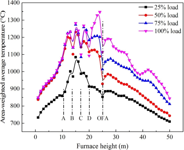
Average temperature distribution profile along the furnace height.
Fig. 6(a) indicates that the high-temperature zone is smaller when the deep peak shaving reaches 25% load. Fig. 7 indicates that for 25% load, the maximum temperature in the furnace was lower than 1100 °C, and the overall temperature distribution in the main combustion zone was also significantly lower than the other three loads, which is not conducive to the stability of combustion and can easily extinguish fires. Therefore, this retrofit scheme opted to use an LNG enriched combustor on the second-tier combustor, and put LNG and pure oxygen into operation to stabilize combustion.
3.1.2. NOx generation in the furnace under deep peak shaving
Fig. 8 depicts the NO concentration distribution in the longitudinal section of the furnace under various loads after the transformation. At 50% and above loads, NO was concentrated in the main combustion zone. When LNG was applied at 25% load, high NO concentration area was not noted. Further, under each load condition, reduction areas were noted, which is beneficial to NO reduction.
Figure 8.

NO concentration distribution in furnace longitudinal section under different loads after reformation of furnace number 2.
Fig. 9 shows the NOx variation curve along the furnace height under different loads of furnace number 2. As evident, when the deep peak shaving reached 25%, the NOx distribution level before and after the application of LNG was significantly reduced. The NOx emission level at the furnace outlet reduced from 380 mg/m3 to 316 mg/m3; this is lower than the retrofit requirement of 350 mg/m3.
Figure 9.

NOx change curve along the furnace height under different loads in furnace number 2.
3.1.3. Analysis of low NOx after LNG application
In order to explore the effect of LNG on NOx reduction, the influence of LNG under 25% load was compared and analyzed. Fig. 10 shows the NO concentration distribution in the longitudinal section of the furnace before and after LNG was applied in furnace number 2 at 25% deep peak shaving. NOx generation with LNG was significantly reduced near the burner outlet, and the reduction zone was notably larger. When LNG was not applied, a notable amount of NO was concentrated near the combustor outlet, indicating that LNG combusted in a reducing atmosphere near the combustor outlet to generate significant number of reducing groups, which reduced the suppression of NO production.
Figure 10.

NO concentration distribution in the longitudinal section of the furnace before and after LNG was applied in furnace number 2 at 25% deep peak shaving.
In order to analyze the principle of steady combustion and low NOx generation after LNG application, we followed the particle movement trajectory of the second and third burner on the front wall of the boiler into the furnace using post-processing software, as shown in Fig. 11. Next, changes in temperature and NO concentration along the process were assessed, as depicted in Fig. 12.
Figure 11.

Particle trajectory of the third burner on the second floor of furnace number 2.
Figure 12.

Temperature and NO concentration change along the particle trajectory before and after LNG application.
Fig. 12(a) indicates that after the LNG was applied, the primary air flow entered the furnace at a high temperature of ignition, and the temperature was higher than 400 °C. When the LNG was not applied, the primary air entered the furnace at a temperature of approximately 75 °C. This suggests that when LNG and pure oxygen were put into operation, active combustion was realized in the primary air duct and the combustion environment was a reducing atmosphere. Thus, the temperature of the primary air stream increased, which was conducive to the ignition and stable combustion of pulverized coal. Further, a reducing combustion environment was created, which significantly inhibited the generation of NOx.
Fig. 12(b) shows two peak areas where NO was intensively generated when LNG was included. The first peak can be attributed is the high-temperature pulverized coal gas stream that ignited in a reducing atmosphere and released part of the HCN to generate NO, which was quickly reduced. The second peak can be attributed to the NO generated during the combustion of pulverized coal particles and was then partially reduced in the recirculation zone. In comparison, when LNG was not included, only a peak of pulverized coal combustion that quickly generated NO was noted, which was 120 ppm higher than when LNG was included; the NO was then partially reduced by the reducing groups in the reduction zone. In addition, the reduction area expanded after LNG was included, and the reduction time of NO was prolonged, which was beneficial to the further reduction of NO.
3.2. Verification of experimental measurements
Table 6 shows part of the measured data of the A side and side B of the furnace outlet under the three loads when the LNG-mixed and oxygen enriched combustion system was applied after the retrofit of boiler number 2. The results show that all the assessment values reached the retrofit target and confirm that the LNG-mixed and oxygen enriched combustion system can effectively modify the combustion performance of the boiler during deep peak shaving.
Table 6.
Measured values of NOx, CO, and O2 at the furnace outlet when LNG-mixed and oxygen enriched combustion system was applied after retrofit of furnace number 2.
| Item | Unit | 135 MW |
100 MW |
75 MW (25%) |
|||
|---|---|---|---|---|---|---|---|
| Side A | Side B | Side A | Side B | Side A | Side B | ||
| Oxygen average value | % | 3.92 | 3.76 | 1.86 | 2.48 | 5.72 | 5.08 |
| 3.84 | 2.22 | 5.4 | |||||
| CO average value | ppm | 35.92 | 28.00 | 23.56 | 27.56 | 27.80 | 28.20 |
| 31.96 | 25.56 | 28.00 | |||||
| NOx (Standard state dry basis, 6% O2) average value | mg/m3 | 254.45 | 282.3 | 333.51 | 330.38 | 288.98 | 306.74 |
| 268.38 | 331.95 | 297.86 | |||||
Fig. 13 compares and analyzes the experimental and calculated values of NOx, CO, and O2 at the furnace outlet when the LNG-mixed and oxygen enriched combustion system was put into operation at 25% load. It is evident that the model employed for this simulation, especially the NOx model, can adapt to the combustion and NOx prediction when the LNG-mixed and oxygen-enriched combustion system was applied. The test value error was small.
Figure 13.

Comparison of furnace outlet test value and calculated value when LNG-mixed and oxygen enriched combustion system was applied at 25% load after retrofit of furnace number 2.
3.3. Comparison with previous research results
In the past, most of the improvement measures have been taken from the perspective of reducing the ignition and combustion characteristics of pulverized coal, and targeted retrofit measures have been proposed based on specific boiler combustion conditions, including increasing primary air temperature, raising coal concentration, and reducing primary air rate and coal fineness [36], [37]. For example, Zhong Lijing et al. [38] from Guangdong Electric Power Group Zhuhai Power Plant focused on a 700 MW tangentially fired boiler, and investigated the impact of burner operation mode on boiler performance during deep-load regulation. The results indicated that when the boiler operating load is below 300 MW, the method of operating the upper three layers of burners effectively raises the reheat steam temperature, improves the turbine efficiency, and reduces the unit's coal consumption. In comparison, this paper demonstrated that after the implementation of the LNG (liquefied natural gas) rich oxygen combustion system, the primary air-coal powder gas stream actively enters the furnace in a state of active combustion. This effectively stabilizes the combustion and reduces the generation of nitrogen oxides (NOx) by inhibiting the formation of reducing groups such as CH3 and CH2 from LNG, resulting in a reduction of NOx emissions at the furnace outlet from 380 mg/m3 to 316 mg/m3, thus meeting the retrofitting objectives in a more targeted and cost-effective manner.
3.4. Economic analysis
In Boiler No. 2, only the bottom burner serves as the ignition source, while load changes are mainly adjusted by the coal air volume of other layers of burners. The layer with the ignition source ensures stable power to guarantee flame stability. When the burner approaches instability in combustion, LNG is injected. The consumption of LNG is determined by the burner and is not significantly related to the load size. It is only used at a very narrow load range, where the LNG consumption is approximately fixed at around 8.3 to 10 kilograms per hour, costing between 45 to 54 RMB per hour. The boiler is fueled with low-quality coal which is difficult to burn. Compared to the original burners using a small diesel gun for ignition with a small amount of diesel, the LNG ignition has stronger ignition capabilities. Using diesel may lead to incomplete combustion products such as soot, which can clog the electrical or bag dust removal systems. In situations of very low load, it may be impossible to resume the operation of these dust removal devices, while using natural gas for ignition and combustion is more environmentally friendly under these low-load conditions throughout the entire process.
4. Conclusion
A retrofit scheme for deep peak shaving and low NOx emission for a 330 MW subcritical pressure face-fired boiler located in Ningxia, China, was introduced. Chemkin software was used to construct a suitable NOx model according to the combustion characteristics of pulverized coal blended with LNG, and a three dimensional CFD model was established. Additionally, the EDC model was used to calculate the combustion characteristics and NOx generation in the boiler before and after the retrofit and during deep peak shaving. Some conclusions can be drawn:
(1) The proposed flexible retrofit plan of placing all four layer burners on the front wall and mixing LNG and oxygen enriched combustion in the second layer burner was successful. When the load was 50% and above, the generation of NOx was significantly reduced; and the goal of retrofit below 350 mg/m3 was achieved. Combustion stability was also guaranteed at low load (25% BMCR), and NOx at the furnace outlet reduced to 316 mg/m3.
(2) The NOx model proposed in this study for co-firing pulverized coal and LNG was consistent with the test data and accurately explains the low NOx emissions that were measured during the on-site low load test. With the help of chemical reaction kinetics, the mechanism of LNG's promotion of NOx reduction during co-combustion was explored highlighting that a large number of reducing groups such as CH3 and CH2 produced by LNG inhibited NOx production.
(3) Addition of LNG and oxygen to the center of the burner improved the stability of combustion. At 25% load, the high-temperature area of the furnace combustion was significantly reduced, and the average temperature of the furnace cross-section was lower than 1100 °C, which was not conducive to stable combustion. However, after the LNG and oxygen-fuel combustion system were operated, the primary air pulverized coal gas flow entered the furnace in a high-intensity combustion state, and the temperature in the furnace was over 400 °C, which effectively stabilized the combustion.
Data availability statement
No data was used for the research described in the article.
CRediT authorship contribution statement
Hujun Zhao: Writing – original draft, Software, Methodology, Conceptualization. Weiqi Li: Validation, Supervision, Software. Jie Zhang: Visualization, Supervision, Investigation. Xian Ding: Writing – review & editing, Software, Methodology, Conceptualization. Zhizhong Kang: Funding acquisition, Formal analysis, Data curation, Conceptualization.
Declaration of Competing Interest
The authors declare the following financial interests/personal relationships which may be considered as potential competing interests:
Weiqi Li reports financial support was provided by National Key Research and Development Program of China. If there are other authors, they declare that they have no known competing financial interests or personal relationships that could have appeared to influence the work reported in this paper.
Acknowledgements
This work is supported by National Key Research and Development Program of China grant number (2022YFB410-0803).
References
- 1.Gu Y., Xu J., Chen D., Wang Z., Li Q. Overall review of peak shaving for coal-fired power units in China. Renew. Sustain. Energy Rev. 2016;54:723–731. [Google Scholar]
- 2.Fang Q.-y., Zhou H.-c., Wang H.-j., Bin Y., Zeng H.-c. Flexibility of a 300 mw arch firing boiler burning low quality coals. J. China Univ. Min. Technol. 2007;17(4):566–571. [Google Scholar]
- 3.Lijin Z., Jian D., Weijie S., et al. Effects of burner operation mode on performance of the boiler under low load conditions. J. Chin. Soc. Power Eng. 2015;35(9):693–698. [Google Scholar]
- 4.Wang G., Deng J., Zhang Y., Zhang Q., Duan L., Hao J., Jiang J. Air pollutant emissions from coal-fired power plants in China over the past two decades. Sci. Total Environ. 2020;741 doi: 10.1016/j.scitotenv.2020.140326. [DOI] [PubMed] [Google Scholar]
- 5.Ma L., Fang Q., Yin C., Wang H., Zhang C., Chen G. A novel corner-fired boiler system of improved efficiency and coal flexibility and reduced nox emissions. Appl. Energy. 2019;238:453–465. [Google Scholar]
- 6.Kanada M., Dong L., Fujita T., Fujii M., Inoue T., Hirano Y., Togawa T., Geng Y. Regional disparity and cost-effective so2 pollution control in China: a case study in 5 mega-cities. Energy Policy. 2013;61:1322–1331. [Google Scholar]
- 7.Yang W., Li W., Guo F., Yang F., Zhang K., Chen F. Emission characteristics and controlling of nox in lean coal-fired boiler of the 330 mw, unit. Clean Coal Technol. 2017;23:107–112. [Google Scholar]
- 8.Zhang X.-B., Zhao H., Yang J.-G. Study on the variation of coal properties for different coal diameters and its effects on combustion characteristics. J. China Coal Soc. 2011;36(6):999–1003. [Google Scholar]
- 9.Yang L., Wen Q.L. Study of 1000 mw ultrasupercritical boiler unit oil-free minimum load stable combustion. Power Stn. Syst. Eng. 2010;26(5):13–16. [Google Scholar]
- 10.Tsumura T., Okazaki H., Dernjatin P., Savolainen K. Reducing the minimum load and nox emissions for lignite-fired boiler by applying a stable-flame concept. Appl. Energy. 2003;74(3–4):415–424. [Google Scholar]
- 11.Zha Q., Li D., Che D., et al. Numerical evaluation of heat transfer and nox emissions under deep-air-staging conditions within a 600 mwe tangentially fired pulverized-coal boiler. Appl. Therm. Eng. 2017;116:170–181. [Google Scholar]
- 12.Wang Y., Zhou Y., Bai N., Han J. Experimental investigation of the characteristics of nox emissions with multiple deep air-staged combustion of lean coal. Fuel. 2020;280 [Google Scholar]
- 13.Wang Z., Wang L., Gao P., Yu Y., Wang R. Analysis of composite sorbents for ammonia storage to eliminate nox emission at low temperatures. Appl. Therm. Eng. 2018;128:1382–1390. [Google Scholar]
- 14.Zeng G., Xu M., Tu Y., Li Z., Cai Y., Zheng Z., Tay K., Yang W. Influences of initial coal concentration on ignition behaviors of low-nox bias combustion technology. Appl. Energy. 2020;278 [Google Scholar]
- 15.Yoshiie R., Kawamoto T., Hasegawa D., Ueki Y., Naruse I. Gas-phase reaction of nox formation in oxyfuel coal combustion at low temperature. Energy Fuels. 2011;25(6):2481–2486. [Google Scholar]
- 16.P. Glarborg, J. Miller, B. Ruscic, S. Klippenstein, Modeling nitrogen chemistry in combustion, 2018.
- 17.Miller J.A., Bowman C.T. Mechanism and modeling of nitrogen chemistry in combustion. Prog. Energy Combust. Sci. 1989;15(4):287–338. [Google Scholar]
- 18.Xiaoyang Q. Analysis and applications of 600 mw supercritical thermal power units without oil depth peak load regulation. Gen. Technol. 2015:36–39. [Google Scholar]
- 19.Li S., Chen Z., He E., Jiang B., Li Z., Wang Q. Combustion characteristics and nox formation of a retrofitted low-volatile coal-fired 330 mw utility boiler under various loads with deep-air-staging. Appl. Therm. Eng. 2017;110:223–233. [Google Scholar]
- 20.Ti S., Kuang M., Wang H., Xu G., Niu C., Liu Y., Wang Z. Experimental combustion characteristics and nox emissions at 50% of the full load for a 600-mwe utility boiler: effects of the coal feed rate for various Mills. Energy. 2020;196 [Google Scholar]
- 21.Li P.Z. Yonghua, Zhou Binxuan. Numerical simulation of low nox swirl burner retrofit. J. Power Eng. 2014;34(4) [Google Scholar]
- 22.Zhou C., Wang Y., Jin Q., Chen Q., Zhou Y. Mechanism analysis on the pulverized coal combustion flame stability and nox emission in a swirl burner with deep air staging. J. Energy Inst. 2019;92(2):298–310. [Google Scholar]
- 23.Liu D., Yan L., Hou S. The evaluation of high temperature corrosion of the inconel 740h in simulated coal-fired environments. Corros. Sci. 2019;161 [Google Scholar]
- 24.Merrick D. Mathematical models of the thermal decomposition of coal: 1. The evolution of volatile matter. Fuel. 1983;62(5):534–539. [Google Scholar]
- 25.Das T. Evolution characteristics of gases during pyrolysis of maceral concentrates of Russian coking coals. Fuel. 2001;80(4):489–500. [Google Scholar]
- 26.Li Z., Miao Z., Shen X., Li J. Prevention of boiler performance degradation under large primary air ratio scenario in a 660 mw brown coal boiler. Energy. 2018;155:474–483. [Google Scholar]
- 27.Silaen A., Wang T. Effect of turbulence and devolatilization models on coal gasification simulation in an entrained-flow gasifier. Int. J. Heat Mass Transf. 2010;53(9–10):2074–2091. [Google Scholar]
- 28.Agraniotis M., Nikolopoulos N., Nikolopoulos A., Grammelis P., Kakaras E. Numerical investigation of solid recovered fuels' co-firing with brown coal in large scale boilers–evaluation of different co-combustion modes. Fuel. 2010;89(12):3693–3709. [Google Scholar]
- 29.Kobayashi H., Howard J., Sarofim A.F. Coal devolatilization at high temperatures. Symp., Int., Combust. 1977;16(1):411–425. [Google Scholar]
- 30.Bestman A. Two-dimensional fluctuating flow and heat transfer to a relativistic radiating gas. Astrophys. Space Sci. 1991;186:1–6. [Google Scholar]
- 31.Nguyen P.D., Ghazal G., Piñera V.C., Battaglia V., Rensgard A., Ekman T., Gazdallah M. Modelling of flameless oxy-fuel combustion with emphasis on radiative heat transfer for low calorific value blast furnace gas. Energy Proc. 2017;120:492–499. [Google Scholar]
- 32.Xing-Xing C., Bao-Sheng J., Wen-Qi Z. Numerical simulation of additionally installed scr denitrification equipment. Therm. Power Gener. 2009;38:51–54. [Google Scholar]
- 33.Rehm M., Seifert P., Meyer B. Theoretical and numerical investigation on the edc-model for turbulence–chemistry interaction at gasification conditions. Comput. Chem. Eng. 2009;33(2):402–407. [Google Scholar]
- 34.Kai C., Bing L., Yuxin W., Hairui Y., Junfu L., Zhang H. Numerical simulation of oxy-coal combustion for a swirl burner with edc model. Chin. J. Chem. Eng. 2014;22(2):193–201. [Google Scholar]
- 35.Wang Z., Deguchi Y., Kamimoto T., Tainaka K., Tanno K. Pulverized coal combustion application of laser-based temperature sensing system using computed tomography–tunable diode laser absorption spectroscopy (ct-tdlas) Fuel. 2020;268 doi: 10.1177/0003702819888214. [DOI] [PubMed] [Google Scholar]
- 36.Qin X. Analysis and application of deep load adjustment technology without oil injection for a 600 mw supercritical thermal power unit. Chin. Power Ind. 2015 (Technical Edition) [Google Scholar]
- 37.Richter M., Mollenbruck F., Obermuller F., Knaut A., Weiser F., Lens H., Lehmann D. Power System Computation Conference. 2016. Flexibilization of steam power plants as partners for renewable energy systems. [Google Scholar]
- 38.Zhong L., Zhong J., Sun W., Yuan L., Fang Q., Tan P. The operating mode of the burner under low load in English has an impact on the boiler performance. J. Power Eng. 2015;35(9):6. [Google Scholar]
Associated Data
This section collects any data citations, data availability statements, or supplementary materials included in this article.
Data Availability Statement
No data was used for the research described in the article.