Abstract
The investigation of the reaction's kinetics is one of the most crucial aspects of the design of a commercial process. The current research investigates the kinetics of Fischer–Tropsch synthesis using a perovskite catalyst. The LaFe0.7 Co0.3 O3 perovskite catalyst was prepared via the thermal sol–gel technique and characterized using BET, XRD, SEM, and H2-TPR techniques. According to operating conditions (e.g. H2/CO: 1–2, pressure: 10–20 barg, temperature: 240–300 °C, and GHSV: 3000 1/h), Fischer–Tropsch reaction kinetics (CO conversion) were carried out in a fixed-bed reactor. Using the framework of Langmuir–Hinshelwood–Hougen–Watson (LHHW) theories, 18 kinetic expressions for CO conversion were derived, and all were fitted to experimental data one by one to determine the optimum condition. The correlation was derived from experimental data and well-fitted using LHHW form (according to the enol mechanism, carbon monoxide and dissociated hydrogen atoms are adsorbed and reacted on the surface of the catalyst) −rCO = kpbCOPCO(bH2PH2)0.5/(1 + bCOPCO + (bH2PH2)0.5)2. Finally, the activation energy of the optimum kinetic model was determined with respect to the Arrhenius equation under various operating conditions. The activation energy of perovskite catalyst is about 106.25 kJ/mol at temperatures 240–300 °C, pressures 10–20 barg, and H2/CO ratios 1–2, which is lower than other types of catalyst. Therefore, the catalyst was activated at a high temperature and demonstrated stable performance without any temperature runaway and coking issues.
Keywords: Fischer–Tropsch synthesis, Perovskite catalyst, Kinetic model
Subject terms: Chemistry, Engineering
Introduction
Fischer–Tropsch synthesis (FTS) is a series of polymeric reactions for converting syngas (a mixture of CO and H2) to liquid hydrocarbons1–3. The high growth of the world's population and the advancement of technology have led to an increase in the demand for liquid fuels; consequently, this process is regarded as a viable alternative for producing valuable fuels4–6 Hydrocarbons with FTS are considered clean fuels due to their low sulfur content7. FT process is regarded as a catalytic process. Metals in the 8–10 group are the most effective catalysts for Fischer–Tropsch synthesis, and among them, Iron and cobalt have demonstrated superior performance compared to other metals. Due to the exothermic nature of the reactions in the FT process, catalyst efficiency reduces accordingly. Therefore, the yield of desirable products decreases due to the resistance of the catalyst to a sudden increase in temperature; thus the behavior of the catalyst at the beginning of the reaction is crucial. Perovskite catalysts have been popular in recent years due to their high thermal stability and diverse performance7,8. The general structure of the perovskite catalysts is ABO3, in which A and B are metal groups and A is a larger cation than B8–10. Furthermore, investigating the kinetic is one of the most important topics for designing commercial processes. Therefore, many researchers are interested in developing a kinetic model for the FT process with a wide range of operating conditions11,12. There have been numerous attempts to define the FT process's kinetics, and there are many kinetic models. All the developing models can be classified into 4 categories: Power Low (PL), Eley-Raidal (ER), Langmuir Hinshelwood Hugon Watson (LHHW), and Termolecular (TM)13–16. Anderso, Dry and Yates suggested the first kinetic equations for Fischer Tropsch synthesis, and it was widely used by other researchers17–19. Boots et al. studied the kinetic equations for Fe and Co catalysts in various operating conditions. They proved that the empirical results demonstrate a significant deviation from model equations. They reported new kinetic equations (Table 1)20,21. In 2010 Ojeda et al.22 investigated the kinetics of Fischer-Trosch synthesis using iron and cobalt catalysts. They stated that the same mechanism could explain the kinetic model of Iron and cobalt, and finally, they developed a single equation for both catalysts (Table 1). Although the actual partial pressure of hydrogen is zero, their predicted model is not zero; therefore, it is not acceptable22. Nikbakht et al.23 reported the catalyst performance along with the kinetic of hydrocarbon-formation reactions for a Fe-Co-Ce catalyst on zeolite support in a fixed bed reactor. They developed the best-fitted model and obtained the kinetic parameters for CO consumption with/without the water term. Einbeigi et al. investigated the kinetics and mechanisms of Fischer–Tropsch synthesis over a %10Fe/%10Co/%80 γ-Al2O3 nanocatalyst prepared by the impregnation method in a fixed bed micro-reactor24. In 2023, Yahyazadeh et al. evaluated the kinetics of the FT reaction with a KMo bimetallic-promoted Fe catalyst supported on carbon nanotubes (CNTs)25. Although there are many studies on the kinetic models of Fischer–Tropsch synthesis using Fe or Co as an active site with various supporters (e.g. γ-alumina or TiO2), few studies have been carried out on the kinetic models of perovskite catalysts. Due to high thermal stability and low deactivation rate, perovskite catalysts have been noticed recently. Therefore, the current research focused on the kinetic and mechanism of Fischer–Tropsch based on perovskite catalyst; that is the LaFe0.7 Co0.3 O3 perovskite catalyst is prepared, characterized and tested in a fixed bed reactor.
Table 1.
Most cited Fischer–Tropsch reaction rate equations.
Material and methods
Materials
All materials were used as received: Iron (III) nitrate (Fe(NO3)3.9H2O, Merck, 98%), Cobalt (II) nitrate (Co(NO3)3.6H2O, Merck, 99%), Lanthanum(III) nitrate (La(NO3)3.6H2O, Merck, 99%), Glycine (NH2CH2COOH, Merck, 99%). The deionized water was applied for catalyst synthesis.
Methods
Catalyst preparation
There are various methods for preparing perovskite oxide such as hydrothermal, microwave, precipitation, sol–gel, etc.26. The La Fe0.7 Co0.3 O3 perovskite catalyst was prepared using the thermal sol–gel method. The catalyst was synthesized at room temperature by an aqueous solution of La(NO3)0.6H2O, Co(NO3)0.6H2O, and Fe(NO3)0.9H2O, then glycine solution was added drop wise to form the gel27,28. The prepared gel was dried at 180 °C for 4 h in the oven, and then calcinated in a furnace at 550 °C (5 °C/min) for 5 h. The sample was pressed into pellets, crushed, and sieved to obtain particles in size between the 40–60 ASTM mesh.
Catalyst characterization
The XRD measurement was carried out using the Philips PW1729 system. The diffraction pattern was obtained using a CuKα lamp with wavelength λ = 1.542°A in the angle range 2θ = 1 to 2θ = 80 and a step size of 0.06. The size of the particle crystals is calculated based on the XRD information and using the Scherer equation.
Brunner Emmett Teller (BET) surface area, pore volume and mean pore diameter of the catalyst were determined using an ASAP 3020 instrument of Micrometrics. The SEM images were recorded using MIRA3 Tescan. Temperature Programmed Reduction (TPR) was carried out on 0.011 g of catalyst heated from 28 to 750 °C (20 °C/min) under 5% H2 in Argon (total gas flow: 50 Ncc/min) with Chembet 3000 system. A CM120 microscope manufactured by Philips did the Transmission Electron Microscopy (TEM) test on the catalysts.
Catalyst activity measurement
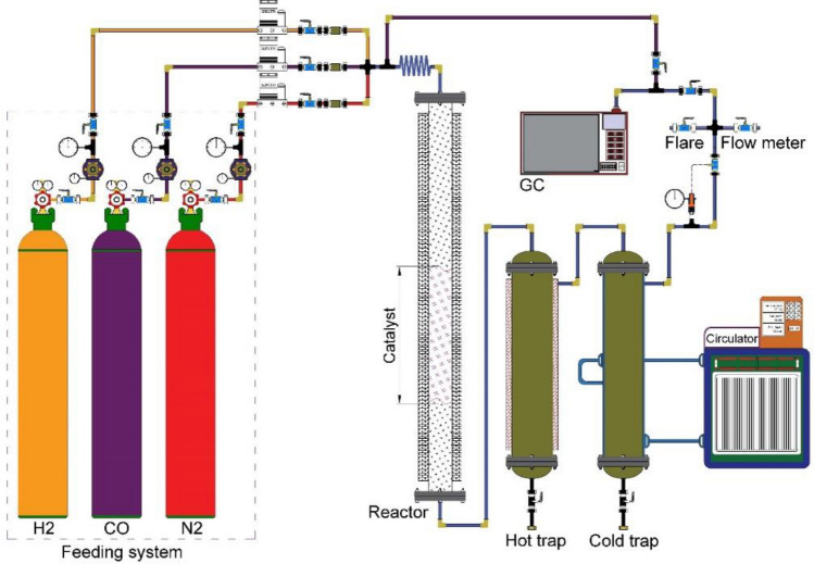
The kinetic tests were performed in a fixed bed reactor using LaFe0.7 Co0.3 O3 catalyst for Fischer Tropsch synthesis. The reactor was made of stainless steel with an 8 mm diameter and 700 mm height. The amount of 1 g catalyst is loaded into one-third of the reactor. The set-up consisted of 3 units: a feeding unit, a reaction unit, and a product separation and analysis unit. Figure 1 shows the schematic of the FT set-up.
Figure 1.
Schematics of the Fischer–Tropsch Set-up.
The catalyst performance was tested under pressure and temperature ranges of 10–20 bar and 240–300 °C, respectively. The feed consisted of carbon monoxide and hydrogen with a percentage of 50% and 50%, respectively. The experimental results are reported in Table 3. The reactor temperature is controlled by a furnace equipped with a temperature controller located around the reactor to maintain a uniform temperature. To prevent choking of the reactor’s outlet in case of the formation of heavy hydrocarbons, the reactor system is equipped with two hot and cold traps to collect light and heavy liquid products. The liquid products are discharged from the traps and gas products are sent to the GC (Agilent 7890) by a stainless steel tube. The feed has three mass flow controllers (MFCs): hydrogen, carbon monoxide, and nitrogen gases. The feed was preheated prior to entering the reactor. The reactor's pressure is adjusted using a pressure valve (Groove) installed before the outlet (Fig. 1).
Table 3.
Experimental condition and results for kinetic tests.
| No | T(K) | H2/CO | PCO (bar) | PH2 (bar) | XCO (%) | XH2 (%) | − rCO *10−3 (mol/min. grcat) |
|---|---|---|---|---|---|---|---|
| 1 | 513.15 | 1.0 | 10.0 | 10.0 | 3.36 | 2.89 | 1.9699 |
| 2 | 513.15 | 2.0 | 3.3 | 6.7 | 11.15 | 20.74 | 2.1750 |
| 3 | 553.15 | 2.0 | 3.3 | 6.7 | 11.59 | 21.09 | 2.0976 |
| 4 | 553.15 | 1.0 | 5.0 | 5.0 | 7.02 | 6.18 | 1.9069 |
| 5 | 533.15 | 1.5 | 6.0 | 9.0 | 6.53 | 8.36 | 2.2094 |
| 6 | 553.15 | 2.0 | 6.7 | 13.3 | 6.69 | 12.71 | 2.4250 |
| 7 | 513.15 | 2.0 | 6.7 | 13.3 | 6.16 | 11.58 | 2.4085 |
| 8 | 533.15 | 1.0 | 10.0 | 10.0 | 3.59 | 3.12 | 2.0234 |
| 9 | 533.15 | 2.0 | 3.3 | 6.7 | 11.48 | 21.70 | 2.1557 |
| 10 | 573.15 | 2.0 | 3.3 | 6.7 | 11.97 | 22.74 | 2.0903 |
| 11 | 573.15 | 1.0 | 5.0 | 5.0 | 7.27 | 6.54 | 1.9061 |
| 12 | 553.15 | 1.5 | 6.0 | 9.0 | 6.76 | 9.15 | 2.2047 |
| 13 | 573.15 | 2.0 | 6.7 | 13.3 | 7.00 | 13.30 | 2.4495 |
| 14 | 533.15 | 2.0 | 6.7 | 13.3 | 6.47 | 12.23 | 2.4357 |
| 15 | 573.15 | 1.0 | 10.0 | 10.0 | 3.69 | 3.28 | 1.9376 |
| 16 | 553.15 | 1.0 | 7.5 | 7.5 | 4.84 | 4.16 | 1.9730 |
| 17 | 513.15 | 2.0 | 3.3 | 6.7 | 10.75 | 20.10 | 2.0981 |
| 18 | 553.15 | 1.0 | 5.0 | 5.0 | 6.99 | 6.22 | 1.9006 |
| 19 | 553.15 | 2.0 | 3.3 | 6.7 | 11.55 | 21.13 | 2.0900 |
| 20 | 533.15 | 1.5 | 6.0 | 9.0 | 6.47 | 8.35 | 2.1890 |
| 21 | 553.15 | 1.0 | 10.0 | 10.0 | 3.61 | 3.32 | 1.9621 |
| 22 | 513.15 | 2.0 | 3.3 | 6.7 | 11.06 | 20.68 | 2.1581 |
| 23 | 553.15 | 1.0 | 5.0 | 5.0 | 6.88 | 6.19 | 1.8706 |
| 24 | 553.15 | 2.0 | 3.3 | 6.7 | 11.55 | 21.13 | 2.0900 |
| 25 | 533.15 | 1.5 | 6.0 | 9.0 | 6.53 | 8.42 | 2.2090 |
| 26 | 533.15 | 1.5 | 6.0 | 9.0 | 6.64 | 8.76 | 2.2467 |
| 27 | 533.15 | 1.5 | 6.0 | 9.0 | 6.60 | 8.58 | 2.2325 |
| 28 | 533.15 | 1.5 | 6.0 | 9.0 | 6.53 | 8.55 | 2.2111 |
| 29 | 513.15 | 1.0 | 5.0 | 5.0 | 6.48 | 5.51 | 1.8980 |
| 30 | 503.15 | 2.0 | 6.7 | 13.3 | 5.86 | 10.84 | 2.3373 |
| 31 | 513.15 | 2.0 | 6.7 | 13.3 | 6.23 | 11.71 | 2.4355 |
| 32 | 513.15 | 1.0 | 10.0 | 10.0 | 3.36 | 2.89 | 1.9695 |
| 33 | 533.15 | 1.5 | 6.0 | 9.0 | 6.54 | 8.50 | 2.2131 |
After loading the catalyst in the reactor, to reduce the catalyst, the mixture of hydrogen and nitrogen gases with a ratio of 1 to 10 (H2 / N2 = 1/10) under atmospheric pressure at 450 °C for 24 h passes throughout the catalyst bed. However, developing kinetic equations requires a series of experiments in specific operating conditions. The intrinsic rate equations were estimated by comparing the theoretical and experimental rates. To determine the kinetic equation in a fixed bed reactor, several factors should be considered as follows19,29,30:
Catalyst activity should not be reduced.
The temperature of the reactor should be constant (Due to the exothermic nature of the Fischer reaction, the operating conditions of the reaction should be considered in such a way that the CO conversion is low.)
No mass transfer limitation is implied in the calculations.
However, to determine the kinetic equation under laboratory conditions, the velocity must be assumed to be uniform along the length of the reactor. Regarding the above assumption, the operating conditions should be implemented in such a way that the CO conversion becomes less than 15%. In these situations, the reaction rate through the reactor is constant and the following equation can be used:
| 1 |
The average rate is:
| 2 |
In order to simplify the kinetics equations, the mass transfer resistance was relinquished from calculations.
According to the ideal gas low the partial pressure of each component calculated as blow:
| 3 |
| 4 |
Result and discussion
Catalyst characterization results
The X-ray diffraction (XRD) of the prepared LaFe0.7Co0.3O3 is presented in Fig. 2a. The catalyst was calcinated at 550 °C and XRD determined the crystal structure. According to Fig. 2 the diffraction peaks of the perovskite structure in the range of 2θ = 30–40 are sharpened, and it is proved that the perovskite structure was formed. The used catalyst was characterized using XRD technique to identify the changes in its structure (Fig. 2b). The size of the LaFe0.7Co0.3O3 crystals was calculated according to X-ray diffraction data with Scherer's equation31:
| 5 |
Figure 2.
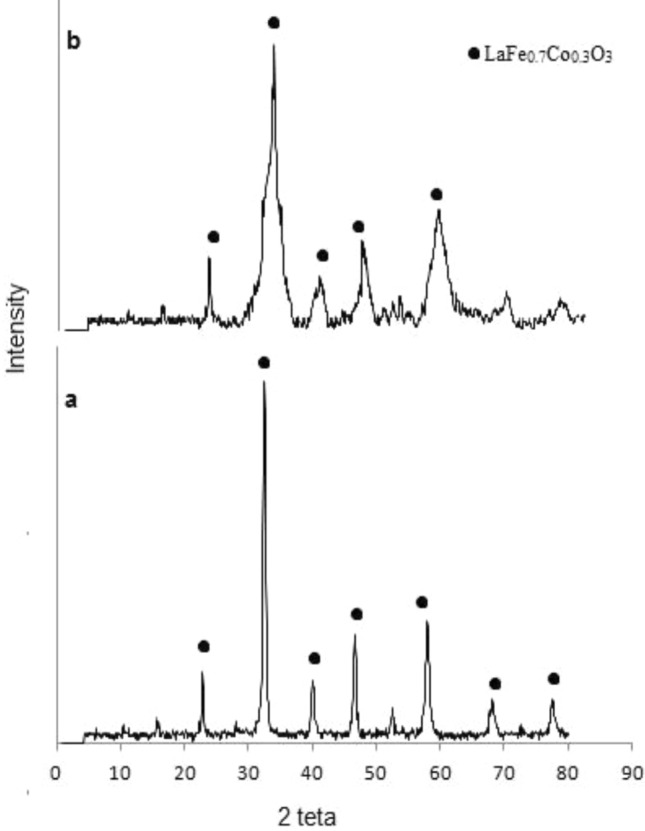
XRD Pattern (a) fresh catalyst (b) used catalyst.
Scherer modified another correlation to calculate the size of crystals31:
| 6 |
According to Scherer's equation, the average particle size was 30.69. The Ln(β) vs. Ln(1/cosθ) line graph was depicted for the LaFe0.7Co0.3O3 crystals using the modified Scherer correlation (Fig. 3). According to the correlation, the predicted size is 33.81. The size difference between the two predicted models is less than 4. Hence, the error percentage is insignificant, so both correlations are acceptable, but the modified Scherer is more compatible than others.
Figure 3.
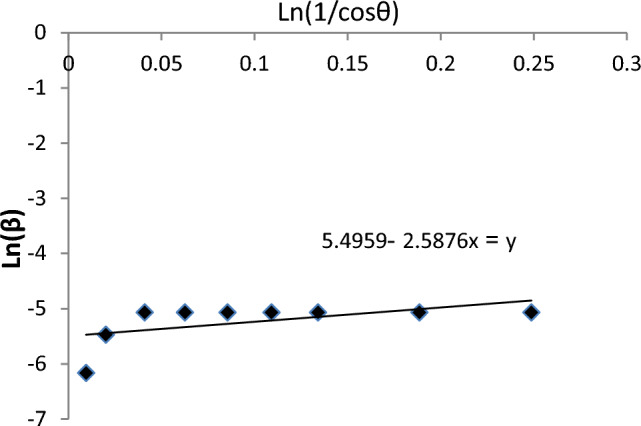
Lnβ verses Ln(1/cosθ) based on XRD results.
The BET test was performed to determine the specific surface area of the catalyst after calcination at 550 °C (Table 2). Whereas, the surface area of the perovskite catalysts is low, but its strong structure makes it valuable.
Table 2.
BET results.
| Surface area (m2/gr) | Pore volume (cm3/gr) | Pore size (nm) | |
|---|---|---|---|
| LaFe0.7Co0.3O3 (Fresh) | 23.7 | 0.0959 | 24.2 |
| LaFe0.7Co0.3O3 (Used) | 10.3 | 0.0625 | 27.6 |
Figure 4 represents the hydrogen consumption of the catalyst after the calcination process. As reported in Fig. 4 there are two reduction peaks between 2000 and 4000 s. The current result is inline with previous studies11,32–34. The first reduction trend appears at low temperatures, roughly 280 °C in the 2500 s, while the second trend appears at temperatures between 380 and 430 °C in the 4200 s. Two peaks in the TPR profile reflect the two reducible cations in the B site (Fe and Co)11.
Figure 4.
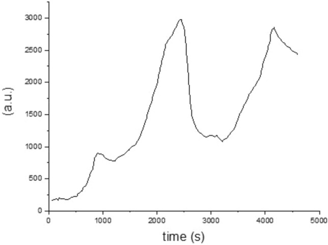
TPR profile of the perovskite catalyst.
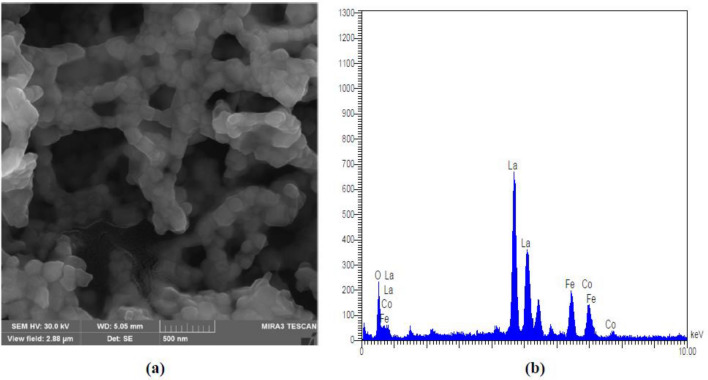
SEM images in Fig. 5a show that porous particles were formed and the EDXS proved that the actual composition of the catalyst is LaFe0.67Co0.32O3 (Fig. 5b).
Figure 5.
(a) SEM micrographs and (b) EDX Spectrum.
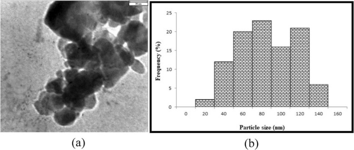
TEM observation of samples shows good distributions of grains of catalysts (Fig. 6). The results show that the particle size is between 20 and 140 nm, and the asymmetric shape of the grains proves that the XRD pattern is accurate.
Figure 6.
TEM Pattern (a) Schematic of catalyst, and (b) particle size distribution.
Kinetic model
The main goal of the current research is to develop an appropriate kinetic model to predict the behavior of the perovskite catalyst (LaFe0.7Co0.3O3) used for the Fischer–Tropsch process. The most crucial aspect of the FT process is elucidating the mechanism of the reaction. Moreover, the mechanisms were determined using various adsorption possibilities of CO and H2 molecules on the catalyst’s surface. There are four mechanisms for FT synthesis, such as carbide, enolic, alkyl, and alkenyl23,35,36. However, the main difference between the mechanisms is the monomer formation; the monomer formation stage was used to estimate the reaction rate.
The activity of LaFe0.7CO0.3O3 perovskite catalyst was studied (Fig. 7) and the results show that after 50 h, the catalyst activity was stable. Additionally, in order to mitigate the impact of deactivation, new catalysts were loaded into each experiment. Therefore the kinetic data is reliable. The product selectivity at the temperature of 553 K and pressure of 20 bar within the catalyst activity range is reported (Fig. 8). The results show that the selectivity of C5+ is in good agreement with previous studies8. Table 3 shows the elementary reaction sets for FT synthesis. The reaction rate expressions for the FTS based on elementary reactions are shown in Table 4. In the current study, to derive all reaction rates, represented in Table 5, the Langmuir–Hinshelwood–Hougen–Watson (LHHW) approach was applied accordingly. In addition, using polymath software, a suitable kinetic model was developed by fitting whole reaction rates against empirical data, and finally, the best kinetic model was chosen based on R2, Rmsd, and MARR.
Figure 7.
Activity diagram during the time (a) CO convention (b) Hydrocarbon Selectivity.
Figure 8.
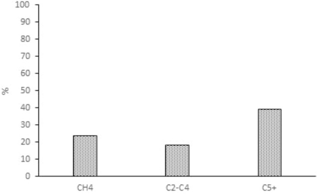
Product selectivity of LaFeCoO catalyst at a temperature of 553 K and pressure of 20 bar.
Table 4.
Elementary reaction sets for Fischer–Tropsch synthesis.
| Model | No | Reaction scheme | Model | No | Reaction scheme |
|---|---|---|---|---|---|
| FT-I | 1 | FT-X | 1 | ||
| 2 | 2 | ||||
| 3 | 3 | ||||
| FT-II | 1 | 4 | |||
| 2 | FT-XI | 1 | |||
| 3 | 2 | ||||
| FT-III | 1 | 3 | |||
| 2 | 4 | ||||
| 3 | 5 | ||||
| 4 | FT-XII | 1 | |||
| FT-IV | 1 | 2 | |||
| 2 | 3 | ||||
| 3 | 4 | ||||
| FT-V | 1 | FT-XIII | 1 | ||
| 2 | 2 | ||||
| 3 | 3 | ||||
| 4 | 4 | ||||
| FT-VI | 1 | 5 | |||
| FT-XIV | 1 | ||||
| 2 | |||||
| 3 | |||||
| 4 | |||||
| FT-VII | 1 | 5 | |||
| 2 | FT-XV | 1 | |||
| 3 | 2 | ||||
| 4 | FT-XVI | 1 | |||
| 5 | 2 | ||||
| 6 | 3 | ||||
| 7 | 4 | ||||
| FT-VIII | 1 | FT-XVII | 1 | ||
| 2 | 2 | ||||
| 3 | 3 | ||||
| 4 | FT-XVIII | 1 | |||
| FT-IX | 1 | 2 | |||
| 2 | 3 | ||||
| 3 | |||||
| 4 | |||||
| 5 |
Table 5.
Reaction rates for Fischer–Tropsch synthesis.
| Model | Rate equation | Model | Rate equation |
|---|---|---|---|
| FT-I (1) | FT-X (1) | ||
| FT-I (2) | FT-X (2) | ||
| FT-II (1) | FT-XI | ||
| FT-II (2) | FT-XII (1) | ||
| FT-III | FT-XII (2) | ||
| FT-IV (1) | FT-XII (3) | ||
| FT-IV (2) | FT-XIII | ||
| FT-V | FT-XIV (1) | ||
| FT-VI | FT-XIV (2) | ||
| FT-VII (1) | FT-XIV (3) | ||
| FT-VII (2) | FT-XV (1) | ||
| FT-VII (3) | FT-XV (2) | ||
| FT-VIII | FT-XVI | ||
| FT-IX (1) | FT-XVII | ||
| FT-IX (2) | FT-XVIII | ||
| FT-IX (3) |
The most appropriate reaction rate (R2) should be close to 1. Moreover, Rmsd and MARR might have a minimum value. The statistical parameters were determined as follows:
1. Square of the coefficient of correlation function (R2):
| 7 |
| 8 |
2. Root Mean Square Deviation (Rmsd)
| 9 |
3. Mean Absolute Relative Residual (MARR):
| 10 |
Comparing experimental data to the model equation demonstrates that the FT-VII (3) model is in good agreement with the empirical results. In this scenario, carbon monoxide and hydrogen atoms are reacted while adsorbed on the surface of a catalyst.
| 11 |
| 12 |
| 13 |
All the reactions are series and have the same reaction rate. If the surface reaction controls the reaction rate, then the CO consumption rate is determined as below:
| 14 |
and for H2 surface adsorption:
| 15 |
| 16 |
| 17 |
where bH2 is equilibrium constant of H2 adsorption step
| 18 |
| 19 |
| 20 |
| 21 |
| 22 |
Finally the CO consumption rate is obtained as below:
| 23 |
The constant coefficient and validation parameters are estimated and presented in Table 6. The MARR percentage of the FT-VII(3) model is 9.65. The model, however, shows less deviation from the experimental data and is consistent with it. The MARR% values of the other obtained kinetic models are presented in Table 7; as it was shown, the FT-VII(3) model having the minimal MARR value fits the experimental data well. The best-fitted kinetic model is an enolic mechanism; in this mechanism, the base component (CHOH) is formed by partial hydrogenation of the absorbed carbon monoxide. According to previous research42,43, the enolic mechanism is much better than the carbide mechanism for bimetallic oxide catalysts.
Table 6.
Values of kinetic parameters of FT-VII(3) model.
| Parameters | Value |
|---|---|
| K0 (mol/min.gcat.) | 0.01756 |
| Ea (kj/mol) | 106.25 |
| bCO (1/bar) | 0.4994 |
| bH2 (1/bar) | 0.1203 |
| R2 | 0.9728 |
| MARR (%) | 9.65 |
Table 7.
Parameters and mean absolute relative residuals (MARR) for the FT kinetic models.
| Kinetic model | k /bCO / bH2 | MARR% | Kinetic model | k /bCO / bH2 | MARR% |
|---|---|---|---|---|---|
| FT-I (1) | 1.47E − 1/14.84E0/1.47E − 1 | 42 | FT-X (1) | 9.05E − 3/49.88E0/– | 10.8 |
| FT-I (2) | 2.16E − 3/14.84E0/– | 10.3 | FT-X (2) | 9.92E − 2/2.57E − 5/– | 53.7 |
| FT-II (1) | 2.64E − 3/–/5.21E − 1 | 14.3 | FT-XI | 3.97E − 3/2.91E − 2/– | 34.3 |
| FT-II (2) | 2.49E − 4/1010.70E0 | 32.6 | FT-XII (1) | 5.46E − 1/2.59E − 3/1.87E0 | 20.3 |
| FT-III | 1.44E − 4/–/101.96E0 | 59.3 | FT-XII (2) | 7.75E − 1/9.47E-5/2.7E0 | 10.69 |
| FT-IV (1) | 9.63E − 3/–/1.11E0 | 29.4 | FT-XII (3) | 2.15E0/1.49E − 1/2.89E − 2 | 10.49 |
| FT-IV (2) | 1.42E − 3/–/4.67E − 1 | 37.2 | FT-XIII | 1.43E − 1/6.63E − 2/6.64E − 2 | 11.46 |
| FT-V | 4.94E − 4/–/1.50E0 | 32.9 | FT-XIV (1) | 9.15E − 3/1.50E0/2.61E − 1 | 54.7 |
| FT-VI | 5.46E − 2/–/3.33E − 6 | 34.8 | FT-XIV (2) | 1.33E − 2/8.11E − 2/5.88E − 3 | 13.1 |
| FT-VII (1) | 3.12E − 3/3.04E0/1.10E0 | 18.6 | FT-XIV (3) | 6.68E − 2/1.69E0/101.9E0 | 10.3 |
| FT-VII (2) | 5.64E − 3/5.56E − 1/6.23E − 2 | 18.3 | FT-XV (1) | 2.38E − 2/102.0E0/– | 13.0 |
| FT-VII (3) | 1.86E0/4.99E − 1/1.20E − 1 | 9.65 | FT-XV (2) | 2.31E0/1.36E − 9/– | 33.5 |
| FT-VIII | 1.18E − 4/9.06E0/8.24E0 | 22.1 | FT-XVI | 2.77E − 1/5.10E − 1/9.86E − 4 | 12.81 |
| FT-IX (1) | 1.99E − 3/1.06E0/1.70E0 | 13.0 | FT-XVII | 25.0E0/2.50E − 4/2.01E0 | 18.9 |
| FT-IX (2) | 3.11E − 3/5.80E − 1/2.06E − 1 | 12.4 | FT-XVIII | 72.66E0/7.16E − 4/2.01E0 | 9.96 |
| FT-IX (3) | 9.79E − 1/5.87E − 2/3.63E − 3 | 29.4 |
In addition, Fig. 9 depicts the comparison between experimental data and the calculated CO consumption rate. Polymath software shows that the experimental and calculated rates were close together and at some point, the experimental and calculated data were overlapped.
Figure 9.
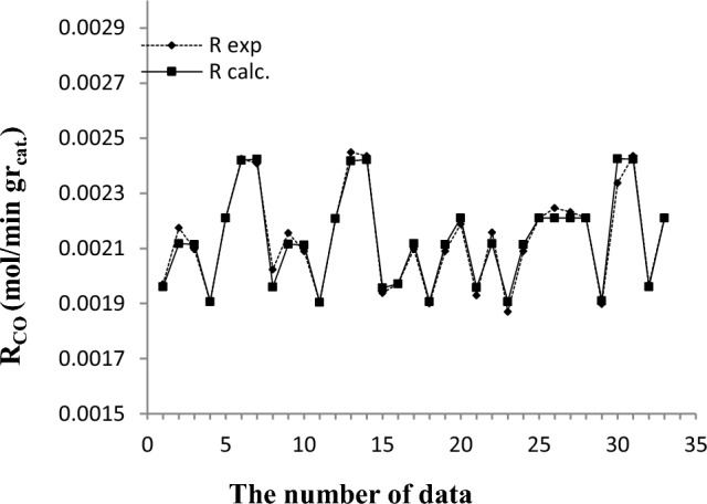
The difference between experimental and calculated reaction rate.
The reaction rate is determined using the model equation and compared with the empirical data (Fig. 10a and b). The compatibility between the model and the experimental data is demonstrated by the closeness of the data to the straight line and the symmetry shape around the straight line.
Figure 10.
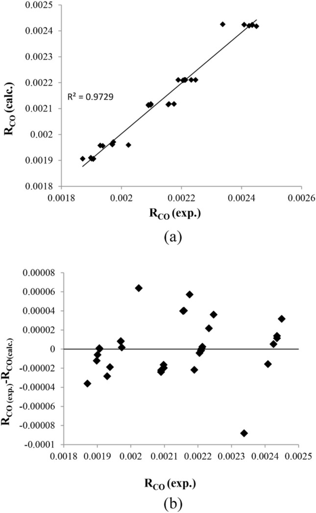
The calculated vs. the experimental reaction rate (a) normal plot, (b) residual plot.
In addition, Fig. 10b presents the calculated against the experimental reaction rate, and it shows that the calculated reaction rate is acceptable for predicting Fischer–Tropsch synthesis. The activation energy of a reaction is obtained by fitting data with the Arrhenius equation in various conditions. The activation energy of hydrocarbon formation is mostly between 75 to 110 kJ/mol37–39. In the current study, the activation energy value is 106.25 kJ/mol. which is close to activation energy reported previously 106.2 kJ/mol by abdollahi et al. and 100and 103 kJ/mol yange et al. and storch et al.40–42. Nevertheless, it was substantially higher than the value of 80.63 and 66.01 kJ/mol which are reported by davies et al.43 and mansouri et al.16. Although the activation energy shows the importance of the diffusion interface, the high activation energies indicate the absence of diffusion effects in the Fischer–Tropsch reaction. Therefore, the pore diffusion restriction led to the low activation energy in the Fischer–Tropsch reaction. The pore size and catalyst structure correspond with the catalyst's preparation method and component16,44.
Conclusion
The performance of LaFe0.7Co0.3O3 perovskite catalyst and kinetic of Fischer–Tropsch synthesis (CO conversion) were investigated in a fixed bed reactor under various operating conditions (e.g. H2/CO: 1–2, pressure: 10–20 barg, temperature: 240–300 °C, and GHSV: 3000 1/h). Several Langmuir–Hinshelwood–Hougen–Watson (LHHW) rate equations were derived. The unknown kinetic parameters such as R2, Rmsd, and MARR were estimated using empirical data in Polymath software. In addition, the kinetic parameters were estimated with non-linear regression and the results show that the FT-VII model predicts CO consumption with high compatibility. Finally, the activation energy was determined with respect to the Arrhenius equation and the optimum value of 106.25 kJ/mol was estimated under various operating conditions. The kinetic parameters correspond with the preparation method and catalyst component. Therefore, the perovskite catalyst is activated at a higher temperature, and consequently, the coking issue is diminished during the operation.
List of symbols
- a
Adsorption parameter
- b
Adsorption parameter
- CV
Free active sites
- d
Mean size of crystal
- E
Activation energy (kJ/mol)
- FCO
Molar flow rate of CO at the inlet (mol min−1)
- K
Dimensionless shape factor
- k
Reaction rate constant
- N
Number experimental data points
- PCO
CO pressure (bar)
- PH2
Hydrogen pressure (bar)
- -rco
The consumption rate of CO (mol/gcat min)
- -RFT
Rate of reaction (mol/ gcat min)
- W
Catalyst mass (gr)
- x
Conversion
- β
Line broadening at half the maximum intensity (FWHM)
- λ
Is the X-ray wavelength
Superscripts
- exp
Experimental value
- cal
Predicted value
Author contributions
All authors contributed to the study conception and design. Material preparation, data collection and experiments analysis were performed by behnoosh Moshtari And Yahya Zamani. Behnoosh Moshtari and Seyed Hassan Hashemabadi investigated the mechanism and derived kinetic model. The first draft of the manuscript was written by Behnoosh Moshtari and all authors commented on previous versions of the manuscript. All authors read and approved the final manuscript.
Data availability
All experimental data were published in the current article. The additional data and information will be provided to individuals upon official request to the corresponding author [Seyed Hasan Hashemabadi].
Competing interests
The authors declare no competing interests.
Footnotes
Publisher's note
Springer Nature remains neutral with regard to jurisdictional claims in published maps and institutional affiliations.
References
- 1.Eschemann TO, de Jong KP. Deactivation behavior of Co/TiO2 catalysts during Fischer-Tropsch synthesis. ACS Catal. 2015;5(6):3181–3188. doi: 10.1021/acscatal.5b00268. [DOI] [Google Scholar]
- 2.Wang Z, et al. Effect of steam during Fischer-Tropsch synthesis using biomass-derived syngas. Catal. Lett. 2017;147:62–70. doi: 10.1007/s10562-016-1881-8. [DOI] [Google Scholar]
- 3.Okoye-Chine CG, et al. A critical review of the impact of water on cobalt-based catalysts in Fischer-Tropsch synthesis. Fuel Process. Technol. 2019;192:105–129. doi: 10.1016/j.fuproc.2019.04.006. [DOI] [Google Scholar]
- 4.Wang D, et al. Cobalt-based Fischer-Tropsch synthesis: Effect of the catalyst granule thermal conductivity on the catalytic performance. Mol. Catal. 2021;502:111395. doi: 10.1016/j.mcat.2021.111395. [DOI] [Google Scholar]
- 5.Zhao X, et al. Comparison of preparation methods of iron-based catalysts for enhancing Fischer-Tropsch synthesis performance. Mol. Catal. 2018;449:99–105. doi: 10.1016/j.mcat.2018.02.022. [DOI] [Google Scholar]
- 6.Abrokwah RY, et al. Effect of titania support on Fischer-Tropsch synthesis using cobalt, iron, and ruthenium catalysts in silicon-microchannel microreactor. Mol. Catal. 2019;478:110566. doi: 10.1016/j.mcat.2019.110566. [DOI] [Google Scholar]
- 7.Teimouri Z, Abatzoglou N, Dalai AK. Kinetics and selectivity study of Fischer-Tropsch synthesis to C5+ hydrocarbons: A review. Catalysts. 2021;11(3):330. doi: 10.3390/catal11030330. [DOI] [Google Scholar]
- 8.Bedel L, et al. La (1− y) Co0.4Fe0.6O3− δ perovskite oxides as catalysts for Fischer-Tropsch synthesis. J. Catal. 2005;235(2):279–294. doi: 10.1016/j.jcat.2005.07.025. [DOI] [Google Scholar]
- 9.Tejuca LG, Fierro JL. Properties and Applications of Perovskite-Type Oxides. CRC Press; 2000. [Google Scholar]
- 10.Wang ZJ, et al. Surface science studies on cobalt Fischer-Tropsch catalysts. ChemCatChem. 2011;3(3):551–559. doi: 10.1002/cctc.201000319. [DOI] [Google Scholar]
- 11.Ao M, et al. Structure and activity of strontium substituted LaCoO3 perovskite catalysts for syngas conversion. J. Mol. Catal. A Chem. 2016;416:96–104. doi: 10.1016/j.molcata.2016.02.020. [DOI] [Google Scholar]
- 12.Jacobs R, et al. Assessing correlations of perovskite catalytic performance with electronic structure descriptors. Chem. Mater. 2019;31(3):785–797. doi: 10.1021/acs.chemmater.8b03840. [DOI] [Google Scholar]
- 13.Das TK, et al. Fischer-Tropsch synthesis: Kinetics and effect of water for a Co/Al2O3 catalyst. In: Davis BH, et al., editors. Fischer-Tropsch Synthesis, Catalysts and Catalysis. Elsevier; 2007. pp. 289–314. [Google Scholar]
- 14.Das TK, et al. Fischer− Tropsch synthesis: Kinetics and effect of water for a Co/SiO2 catalyst. Energy Fuels. 2005;19(4):1430–1439. doi: 10.1021/ef049869j. [DOI] [Google Scholar]
- 15.Rautavuoma AO, Van der Baan H. Kinetics and mechanism of the fischer tropsch hydrocarbon synthesis on a cobalt on alumina catalyst. Appl. Catal. (Netherlands) 1981;1(5):247–272. [Google Scholar]
- 16.Mansouri M, et al. Kinetics studies of nano-structured cobalt–manganese oxide catalysts in Fischer-Tropsch synthesis. J. Ind. Eng. Chem. 2013;19(4):1177–1183. doi: 10.1016/j.jiec.2012.12.015. [DOI] [Google Scholar]
- 17.Zennaro R, Tagliabue M, Bartholomew CH. Kinetics of Fischer-Tropsch synthesis on titania-supported cobalt. Catal. Today. 2000;58(4):309–319. doi: 10.1016/S0920-5861(00)00264-9. [DOI] [Google Scholar]
- 18.Yates IC, Satterfield CN. Intrinsic kinetics of the Fischer-Tropsch synthesis on a cobalt catalyst. Energy Fuels. 1991;5(1):168–173. doi: 10.1021/ef00025a029. [DOI] [Google Scholar]
- 19.Dry ME. Advances in fishcher-tropsch chemistry. Ind. Eng. Chem. Prod. Res. Dev. 1976;15(4):282–286. [Google Scholar]
- 20.Botes FG, Breman BB. Development and testing of a new macro kinetic expression for the iron-based low-temperature Fischer− Tropsch reaction. Ind. Eng. Chem. Res. 2006;45(22):7415–7426. doi: 10.1021/ie060491h. [DOI] [Google Scholar]
- 21.Botes FG, van Dyk B, McGregor C. The development of a macro kinetic model for a commercial Co/Pt/Al2O3 Fischer− Tropsch catalyst. Ind. Eng. Chem. Res. 2009;48(23):10439–10447. doi: 10.1021/ie900119z. [DOI] [Google Scholar]
- 22.Ojeda M, et al. CO activation pathways and the mechanism of Fischer-Tropsch synthesis. J. Catal. 2010;272(2):287–297. doi: 10.1016/j.jcat.2010.04.012. [DOI] [Google Scholar]
- 23.Nikbakht N, Mirzaei AA, Atashi H. Kinetic modeling of the Fischer-Tropsch reaction over a zeolite supported Fe-Co-Ce catalyst prepared using impregnation procedure. Fuel. 2018;229:209–216. doi: 10.1016/j.fuel.2018.04.132. [DOI] [Google Scholar]
- 24.Einbeigi A, et al. Development of new comprehensive kinetic models for Fischer-Tropsch synthesis process over Fe–Co/γ-Al2O3 nanocatalyst in a fixed-bed reactor. J. Taiwan Inst. Chem. Eng. 2019;103:57–66. doi: 10.1016/j.jtice.2019.07.004. [DOI] [Google Scholar]
- 25.Yahyazadeh A, et al. Comprehensive kinetic study for Fischer-Tropsch reaction over KMoFe/CNTs nano-structured catalyst. Can. J. Chem. Eng. 2023;101(6):3132–52. doi: 10.1002/cjce.24807. [DOI] [Google Scholar]
- 26.Liu Z, et al. Structural and microstructural effects of Mo3+/Mo5+ codoping on properties and photocatalytic performance of nanostructured TiO2 Thin films. J. Phys. Chem. C. 2019;123(18):11781–11790. doi: 10.1021/acs.jpcc.9b02667. [DOI] [Google Scholar]
- 27.Mohammadi M, et al. Synthesis of high surface area nanocrystalline anatase-TiO2 powders derived from particulate sol-gel route by tailoring processing parameters. J. Sol-gel Sci. Technol. 2006;40(1):15–23. doi: 10.1007/s10971-006-8267-0. [DOI] [Google Scholar]
- 28.Cordero-Cabrera M, Walker G, Grant D. Effect of processing parameters on the particle size and stabilisation of Titania sols. J. Mater. Sci. 2005;40(14):3709–3714. doi: 10.1007/s10853-005-2825-7. [DOI] [Google Scholar]
- 29.Sie S, Senden M, Van Wechem H. Conversion of natural gas to transportation fuels via the shell middle distillate synthesis process (SMDS) Catal. Today. 1991;8(3):371–394. doi: 10.1016/0920-5861(91)80058-H. [DOI] [Google Scholar]
- 30.Kellner CS, Bell AT. The kinetics and mechanism of carbon monoxide hydrogenation over alumina-supported ruthenium. J. Catal. 1981;70(2):418–432. doi: 10.1016/0021-9517(81)90354-7. [DOI] [Google Scholar]
- 31.Monshi A, Foroughi MR, Monshi MR. Modified Scherrer equation to estimate more accurately nano-crystallite size using XRD. World J. Nano Sci. Eng. 2012;2(3):154–160. doi: 10.4236/wjnse.2012.23020. [DOI] [Google Scholar]
- 32.Bedel L, et al. Co0 from partial reduction of La (Co, Fe) O3 perovskites for Fischer-Tropsch synthesis. Catal. Today. 2003;85(2–4):207–218. doi: 10.1016/S0920-5861(03)00388-2. [DOI] [Google Scholar]
- 33.Escalona N, Fuentealba S, Pecchi G. Fischer-Tropsch synthesis over LaFe1− xCoxO3 perovskites from a simulated biosyngas feed. Appl. Catal. A Gen. 2010;381(1–2):253–260. doi: 10.1016/j.apcata.2010.04.022. [DOI] [Google Scholar]
- 34.Liu G, et al. Bi-metal Cu–Co from LaCo1−xCuxO3 perovskite supported on zirconia for the synthesis of higher alcohols. Fuel Process. Technol. 2014;128:289–296. doi: 10.1016/j.fuproc.2014.07.010. [DOI] [Google Scholar]
- 35.Sun Y, et al. Fischer-Tropsch synthesis using iron based catalyst in a microchannel reactor: Performance evaluation and kinetic modeling. Int. J. Hydrogen Energy. 2017;42(49):29222–29235. doi: 10.1016/j.ijhydene.2017.10.022. [DOI] [Google Scholar]
- 36.Mousavi S, et al. Generalized kinetic model for iron and cobalt based Fischer-Tropsch synthesis catalysts: Review and model evaluation. Appl. Catal. A Gen. 2015;506:57–66. doi: 10.1016/j.apcata.2015.08.020. [DOI] [Google Scholar]
- 37.Lox ES, Froment GF. Kinetics of the Fischer-Tropsch reaction on a precipitated promoted iron catalyst. 2. Kinetic modeling. Ind. Eng. Chem. Res. 1993;32(1):71–82. doi: 10.1021/ie00013a011. [DOI] [Google Scholar]
- 38.Huff GA, Jr, Satterfield CN. Liquid accumulation in catalyst pores in a Fischer-Tropsch fixed-bed reactor. Ind. Eng. Chem. Process Des. Dev. 1985;24(4):986–995. doi: 10.1021/i200031a015. [DOI] [Google Scholar]
- 39.Dictor RA, Bell AT. Fischer-Tropsch synthesis over reduced and unreduced iron oxide catalysts. J. Catal. 1986;97(1):121–136. doi: 10.1016/0021-9517(86)90043-6. [DOI] [Google Scholar]
- 40.Yang C-H, Massoth F, Oblad A. Kinetics of CO+ H2 Reaction Over co-Cu-Al2O3 Catalyst. ACS Publications; 1979. [Google Scholar]
- 41.Abdollahi M, et al. Fischer-Tropsch study over impregnated silica-supported cobalt–iron nanocatalyst. J. Iran. Chem. Soc. 2017;14:245–256. doi: 10.1007/s13738-016-0975-y. [DOI] [Google Scholar]
- 42.Storch, H.H., Golumbic, N., Anderson, R.B. The Fischer-Tropsch and related syntheses: including a summary of theoretical and applied contact catalysis. (1951).
- 43.Davies I, Möller KP. Development of a kinetic model for low temperature Fischer-Tropsch synthesis. Chem. Eng. Sci. 2021;241:116666. doi: 10.1016/j.ces.2021.116666. [DOI] [Google Scholar]
- 44.Sari A, Zamani Y, Taheri SA. Intrinsic kinetics of Fischer-Tropsch reactions over an industrial Co–Ru/γ-Al2O3 catalyst in slurry phase reactor. Fuel Process. Technol. 2009;90(10):1305–1313. doi: 10.1016/j.fuproc.2009.06.024. [DOI] [Google Scholar]
Associated Data
This section collects any data citations, data availability statements, or supplementary materials included in this article.
Data Availability Statement
All experimental data were published in the current article. The additional data and information will be provided to individuals upon official request to the corresponding author [Seyed Hasan Hashemabadi].


