

Summary
Organ-on-chip technology is a powerful tool for in vitro modeling. Combining it with organoids overcomes lumen inaccessibility while preserving cellular diversity and function of the intestinal epithelium. Here, we present a protocol for generating and analyzing organ-on-chips using human and mouse intestinal organoids. This protocol covers organoid line establishment, single-cell dissociation, chip preparation, and seeding. It outlines procedures for permeability assays, RNA isolation, staining, and imaging. Additionally, we describe independent stimulation and sampling of the apical and basal side.
Subject areas: cell Biology, cell culture, cell isolation, cell-based assays, organoids, tissue Engineering
Graphical abstract
Highlights
-
•
Generation of organ-on-chip using human and murine intestinal organoids
-
•
Analysis of barrier integrity by functional assay and microscopy
-
•
Independent and concurrent sampling and stimulation of apical and basal side
-
•
Tool to study transcriptome and secretome and implement co-culture
Publisher’s note: Undertaking any experimental protocol requires adherence to local institutional guidelines for laboratory safety and ethics.
Organ-on-chip technology is a powerful tool for in vitro modeling. Combining it with organoids overcomes lumen inaccessibility while preserving cellular diversity and function of the intestinal epithelium. Here, we present a protocol for generating and analyzing organ-on-chips using human and mouse intestinal organoids. This protocol covers organoid line establishment, single-cell dissociation, chip preparation, and seeding. It outlines procedures for permeability assays, RNA isolation, staining, and imaging. Additionally, we describe independent stimulation and sampling of the apical and basal side.
Before you begin
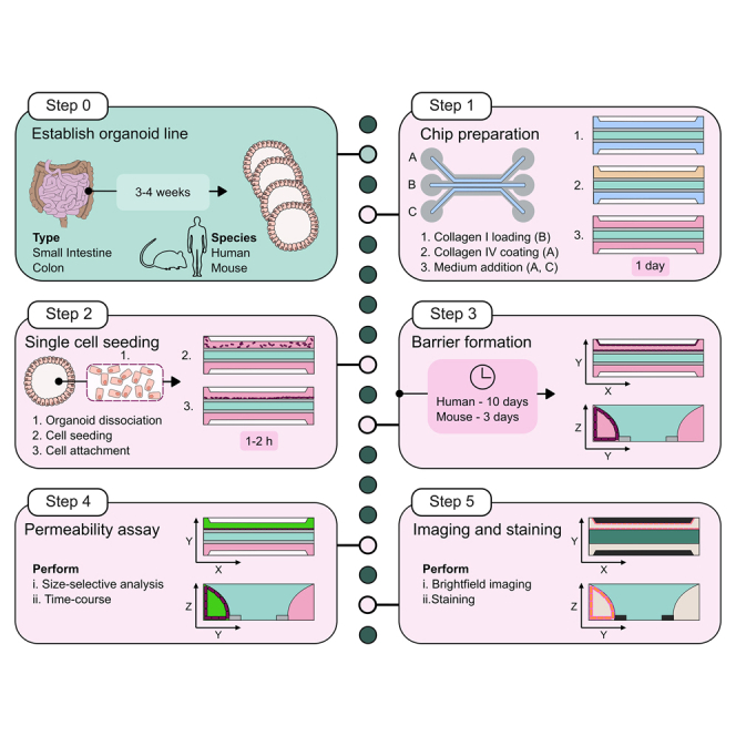
We describe the generation of an organ-on-chip (OoC) platform using human and murine intestinal organoids derived from adult stem cells. It facilitates the accomplishment of easily accessing the luminal space and apical side of the cell, a disadvantage of traditional 3D culture, and additionally introduces flow as a physiological mechanic stimulus. It serves as a versatile tool to stimulate and analyze intestinal epithelial cells from both the basal and apical side leveraging the full potential of organoids. Additionally, it serves as a solid starting point for subsequent modifications such as directed differentiation, introduction of other cell types, addition of bacteria, metabolites or various compounds.
This protocol gives detailed information on how the 3D organoids must be cultured and dissociated into single cell suspension to achieve high quality starting material. Additionally, it describes how the OoC is prepared to promote cell attachment and tube formation as well as giving information on pipetting techniques essential for handling low-volume microfluidic systems. Furthermore, it serves as an initial guide for a variety of analysis approaches including but not limited to imaging, gene expression studies, barrier integrity and cytokine release analysis. The protocol specifically describes the use of organoids from the terminal part of the colon. Nevertheless, it is also applicable to organoids derived from other regions of the colon and small intestine.
Institutional permission
Primary human intestinal material was sampled from intestines that could not be used for transplantation. The organs were procured from donors via Novabiosis, Inc. (Research Triangle Park Durham, North Carolina, USA) following ethical committee approval from the Organ Procurement Organizations (OPO), in line with the consent and deidentification guidelines established by the OPOs and the United Network for Organ Sharing (UNOS), under the US transplantation network framework. The immediate family members of the donors granted permission for organ donation while preserving the patient’s privacy. This donation approval aligns with the guidelines provided by the federal organization UNOS and the Federal Drug Administration (FDA). All procedures were conducted following standard operating procedures with the appropriate approval of the Ethics and Scientific Committees.
All procedures outlined in this protocol were conducted adhering to the principles stipulated in the WMA Declaration of Helsinki.
Mouse tissue was obtained from C57BL6J mice (<12 weeks of age) provided by the Interdisciplinary Neurobehavioral Core (INBC) of Heidelberg University. All experimental procedures adhered to the ethical guidelines set forth by the local governing body, ‘Regierungspräsidium’ in Karlsruhe, Germany.
Organoids are derived from primary material and therefore it is essential to receive institutional and ethical approval before starting any experiment. Ensure that relevant regulatory standards are fulfilled during subsequent experiments.
Organoid generation
This protocol uses primary cells to establish an OoC. It is therefore essential to establish organoid cultures from intestinal tissue of either human or murine origin. Detailed protocols on crypt isolation and organoid generation have been extensively described elsewhere.1,2 Organoid maintenance requires slight modifications to support an enrichment of proliferative cells as required for OoC establishment. In the protocol below, we describe methods using human descending colon and murine distal colon organoids to generate OoC.
Key resources table
| REAGENT or RESOURCE | SOURCE | IDENTIFIER |
|---|---|---|
| Antibodies | ||
| Alexa Fluor 488 goat anti-rabbit IgG (H + L) | Life Technologies | Cat# A11034 |
| ZO-1 polyclonal antibody | Life Technologies | Cat#61-7300 |
| Biological samples | ||
| Human descending colon organoids | Novobiosis | N/A |
| Mouse distal colon organoids | INBC, Heidelberg University | N/A |
| Chemicals, peptides, and recombinant proteins | ||
| 4% PFA (paraformaldehyde solution 4% in PBS) | Santa Cruz Biotechnology | Cat#sc-281692 |
| A83-01 | Sigma-Aldrich | Cat#SML0788 |
| Accutase (StemPro Accutase cell dissociation reagent) | Gibco | Cat#A11105 |
| Advanced DMEM/F12 | Thermo Fisher Scientific | Cat#12634028 |
| B27 | Thermo Fisher Scientific | Cat#17504044 |
| Bovine collagen I (TeloCol-6 bovine type I collagen solution, 6 mg/mL) | Advanced Biomatrix | Cat#5225 |
| BSA (bovine serum albumin) | Sigma-Aldrich | Cat#A3294 |
| CHIR99021 | Sigma-Aldrich | Cat#SML1046 |
| FBS (fetal bovine serum) | Capricorn Scientific | Cat#FBS-DIA-12A |
| FGF-2 | PeproTech | Cat#100-18C |
| FITC 4 kDa (fluorescein isothiocyanate-dextran 3,000–5,000 Da) | Sigma-Aldrich | Cat#FD4 |
| GlutaMAX | Thermo Fisher Scientific | Cat#35050038 |
| HBSS | Fisher Scientific | Cat#14175129 |
| HEPES | Capricorn Scientific | Cat#HEP-B |
| Hoechst 33342 | Fisher Scientific | Cat#H3570 |
| Human collagen IV (derived from human placenta) | Sigma-Aldrich | Cat#C5533 |
| IGF-1 | BioLegend | Cat#590906 |
| [Leu15]-Gastrin I | Sigma-Aldrich | Cat#G9145 |
| Matrigel | Corning | Cat#356231 |
| Mouse collagen IV | Corning | Cat#354233 |
| NaHCO3 | Carl Roth | Cat#6885.1 |
| Nicotinamide | Sigma-Aldrich | Cat#A7250 |
| Noggin | PeproTech | Cat#250-38 |
| N-acetyl-cysteine | Sigma-Aldrich | Cat#A7250 |
| PBS (Dulbecco’s PBS (1x), w/o Ca & Mg, w/o phenol red) | Capricorn Scientific | Cat#PBS-1A |
| Phalloidin ATTO 643 | ATTO-TEC | Cat#AD 643-81 |
| Primocin | InvivoGen | Cat#ant-pm-1 |
| Rat collagen I (Cultrex 3-D culture matrix rat collagen I) | Bio-Techne | Cat#3447-020-01 |
| Recombinant murine EGF | PeproTech | Cat#315-09 |
| SB202190 | Tocris | Cat#1264 |
| Surrogate WNT protein | U-protein | Cat#N-001 |
| TRITC 70 kDa (tetramethylrhodamine isothiocyanate-dextran 65,000–80,000 Da) | Sigma-Aldrich | Cat#T1162 |
| Triton X-100 | Sigma-Aldrich | Cat#T8787 |
| Tween 20 | Carl Roth | Cat#9127.1 |
| Valproic acid | Sigma-Aldrich | Cat#PHR1061 |
| Y-27632 | Hölzel Diagnostika | Cat#HY-10583 |
| Critical commercial assays | ||
| LEGENDplex human inflammation panel 1 (optional) | BioLegend | Cat#740809 |
| RNeasy plus micro kit (optional) | QIAGEN | Cat#74034 |
| Experimental models: Cell lines | ||
| R-Spondin1-conditioned medium (stably transfected HEK293T cells) | kindly provided by Hugo de Jonge | N/A |
| Software and algorithms | ||
| 3D ImageJ Suite | Ollion, J. et al.3 | 3D Suite ImageJ (frama.io) |
| BioVOXXEL plugin | Brocher, J. et al.4 | biovoxxel.de |
| ImageJ software | Schindelin, J. et al.5 | https://imagej.nih.gov/ij/ |
| Inkscape | The Inkscape team | inkscape.org |
| Other | ||
| 1.5 mL tubes | Sarstedt | Cat#72.706 |
| 15 mL conical tubes | neoLab Migge | Cat#352070 |
| 24-well plate | Corning | Cat#3526 |
| 40 μm EASYstrainer cell sieves | Greiner Bio-one | Cat#542140 |
| 96-well plate | neoLab Migge | Cat#C-8206 |
| Adhesive plate seals | Fisher Scientific | Cat#AB0558 |
| Chips contained in OrganoPlate 3-lane 40 | Mimetas | N/A |
| Combitips, 0.1 mL (Advanced Biopur pipette tips) | Eppendorf | Cat#30089650 |
| Combitips, 2.5 mL (Advanced Biopur pipette tips) | Eppendorf | Cat#12614597 |
| Confocal microscope (e.g., AX) | Nikon | N/A |
| Electronic multi-dispenser pipette | Eppendorf | Cat#4987000380 |
| Fluorescence microscope (e.g., Eclipse Ti2) | Nikon | N/A |
| Microscope stage incubator | Tokai Hit | N/A |
| Neubauer counting chamber | neoLab Migge | Cat#191844172 |
| OrganoFlow | Mimetas | N/A |
| OrganoPlate stand | Mimetas | N/A |
| Pipette, 10 mL | Greiner Bio-one GmbH | Cat#607180 |
| Pipette controller accu-jet pro | Brand | Cat#10234982 |
| Pipette tip, 200 μL, Biosphere plus sterile | Sarstedt | Cat#70.760.202 |
Materials and equipment
Base medium
| Reagent | Final concentration | Amount |
|---|---|---|
| advanced DMEM/F12 | N/A | 489 mL |
| HEPES (1 M) | 10 mM | 5 mL |
| GlutaMAX (100x) | 1x | 5 mL |
| Primocin (50 mg/mL) | 100 μg/mL | 1 mL |
| Total | N/A | 500 mL |
Store at 4°C for up to 4 weeks.
Human Expansion Medium
| Reagent | Final concentration | Amount |
|---|---|---|
| advanced DMEM/F12 | N/A | 14.9 mL |
| R-Spondin1-conditioned medium, stably transfected HEK293T cells (5x) | 1x | 4 mL |
| B27 (50x) | 1x | 400 μL |
| HEPES (1 M) | 10 mM | 200 μL |
| GlutaMAX (100x) | 1x | 200 μL |
| Noggin (20 μg/mL) | 100 ng/mL | 100 μL |
| N-Acetyl-Cysteine (500 mM) | 1 mM | 40 μL |
| Primocin (50 mg/mL) | 100 μg/mL | 40 μL |
| surrogate Wnt (0.5 μM) | 0.5 nM | 20 μL |
| EGF (50 μg/mL) | 50 ng/mL | 20 μL |
| IGF-1 (100 μg/mL) | 100 ng/mL | 20 μL |
| FGF-2 (100 μg/mL) | 50 ng/mL | 10 μL |
| A83-01 (5 mM) | 500 nM | 2 μL |
| Leu[15]-Gastrin I (100 μM) | 10 nM | 2 μL |
| Y-27632 (10 mM)∗ | 10 μM | 2 μL |
| Total | N/A | 20 mL |
Store at 4°C for up to 2 weeks. ∗Only add for the 1–3 days after initial culture, thawing or expansion.
Human Growth Medium
| Reagent | Final concentration | Amount |
|---|---|---|
| advanced DMEM/F12 | N/A | 14.8 mL |
| R-Spondin1-conditioned medium; stably transfected HEK293T cells (5x) | 1x | 4 mL |
| B27 (50x) | 1x | 400 μL |
| HEPES (1 M) | 10 mM | 200 μL |
| GlutaMAX (100x) | 1x | 200 μL |
| Nicotinamide | 10 mM | 200 μL |
| Noggin (20 μg/mL) | 100 ng/mL | 100 μL |
| N-Acetyl-Cysteine (500 mM) | 1.25 mM | 50 μL |
| Primocin (50 mg/mL) | 100 μg/mL | 40 μL |
| surrogate Wnt (0.5 μM) | 0.5 nM | 20 μL |
| EGF (50 μg/mL) | 50 ng/mL | 20 μL |
| SB202190 (30 mM) | 10 μM | 6.7 μL |
| A83-01 (5 mM) | 500 nM | 2 μL |
| Leu[15]-Gastrin I (100 μM) | 10 nM | 2 μL |
| Y-27632 (10 mM)∗ | 10 μM | 2 μL |
| Total | N/A | 20 mL |
Store at 4°C for up to 2 weeks. ∗Only add for the 1–3 days after initial culture, thawing or expansion.
Mouse Growth Medium
| Reagent | Final concentration | Amount |
|---|---|---|
| advanced DMEM/F12 | N/A | 14.8 mL |
| R-Spondin1-conditioned medium; stably transfected HEK293T cells (5x) | 1x | 4 mL |
| B27 (50x) | 1x | 400 μL |
| HEPES (1 M) | 10 mM | 200 μL |
| GlutaMAX (100x) | 1x | 200 μL |
| Noggin (20 μg/mL) | 100 ng/mL | 100 μL |
| N-Acetyl-Cysteine (500 mM) | 1.25 mM | 50 μL |
| Primocin (50 mg/mL) | 100 μg/mL | 40 μL |
| surrogate Wnt (0.5 μM) | 0.5 nM | 20 μL |
| EGF (50 μg/mL) | 50 ng/mL | 20 μL |
| CHIR99021 (3 mM) | 3 μM | 2 μL |
| Valproic acid | 1 mM | 3.2 μL |
| Y-27632∗ | 10 μM | 2 μL |
| Total | N/A | 20 mL |
Store at 4°C for up to 2 weeks. ∗Only add for the 1–3 days after initial culture, thawing or expansion.
Human ECM mix
| Reagent | Final concentration | Amount |
|---|---|---|
| Bovine Collagen I (6 mg/mL) | 5 mg/mL | 108 μL |
| Neutralization buffer | N/A | 12 μL |
| Total | N/A | 120 μL |
Prepare directly before use and keep on ice.
Murine ECM mix
| Reagent | Final concentration | Amount |
|---|---|---|
| Rat-tail collagen I (5 mg/mL) | 4 mg/mL | 80 μL |
| HEPES (1 M) | 100 mM | 10 μL |
| NaHCO3 (37 g/L) | 3.7 g/L | 10 μL |
| Total | N/A | 100 μL |
Prepare directly before use and keep on ice.
Human coating solution
| Reagent | Final concentration | Amount |
|---|---|---|
| Human collagen IV (1 mg/mL) | 25 μg/mL | 28 μL |
| PBS | N/A | 1072 μL |
| Total | N/A | 1100 μL |
Prepare directly before use and keep on ice.
Murine coating solution
| Reagent | Final concentration | Amount |
|---|---|---|
| Murine collagen IV (0.829 mg/mL) | 200 μg/mL | 265 μL |
| Matrigel (8.9 mg/mL) | 100 μg/mL | 12.3 μL |
| PBS | N/A | 822.7 μL |
| Total | N/A | 1100 μL |
Prepare directly before use and keep on ice.
Blocking solution
| Reagent | Final concentration | Amount |
|---|---|---|
| FBS | 2% | 200 μL |
| BSA | 2% | 200 μL |
| Tween 20 | 0.1% | 10 μL |
| PBS | N/A | 9.6 mL |
| Total | N/A | 10 mL |
Store at −20°C for up to 1 year.
Step-by-step method details
Timing: 4–6 weeks
Organoid maintenance
This section of the protocol describes how the organoids are expanded and grown prior to the OoC generation. After establishing an organoid line, organoids need to be expanded at least 3 times to ensure a homogenous culture before being used for the final expansion step that generated the organoids source for OoC generation.
Day 1
Note: Cell culture 24-well plates are kept in the incubator >24 h prior to use to ensure Matrigel dome formation.
-
1.
Prepare a 15 mL tube by adding 5 mL cold base medium to it.
-
2.
Remove the medium from the desired number of wells to be harvested, and discard.
-
3.Add 1 mL cold base medium to one of the wells.
-
a.Aspirate and dispense the volume several times until the organoids are released from the Matrigel dome.
-
b.Repeat this using the same medium for all subsequent wells.
-
a.
Note: Up to 4 wells of a 24-well plate can be pooled in 1 mL. Up to 8 wells can be pooled in one 15 mL tube.
-
4.
Transfer the organoid suspension to the 15 mL tube containing 5 mL cold base medium.
Note: If you expect a low number of organoids, an additional 1 mL base medium can be used to flush the wells to collect remaining organoids.
Note: Human and mouse organoids need slightly different dissociation protocols and media composition as indicated below.
-
5.For human organoids:
-
a.Equip a 10 mL pipette with a 200 μL pipette tip.
-
i.Then aspirate and dispense the organoid suspension 3 times.Note: Avoid the formation of foam by incomplete release of the full volume.Note: This step removes the Matrigel completely whilst keeping the organoids intact. Murine organoids are much more fragile and would be dissociated by this step.
-
i.
-
b.Centrifuge the suspension at 150 g for 5 min at 4°C.Note: The centrifuge settings should be adjusted to a slow brake to avoid disturbing the pellet.
-
c.Remove the supernatant completely.Note: The last 200 μL can be removed using a pipette to avoid disturbing the pellet.
-
d.Add 50 μL Accutase per well, resuspend the pellet and incubate it for 45 s at 37°C.
-
e.Add 6 mL cold base medium and repeat step 5a.
-
i.Then aspirate and dispense the organoid suspension 10 times.Note: In this step the organoids are dissociated into fragments that can be used to expand the culture.
-
i.
-
f.Centrifuge the suspension again as in 5b.
-
a.
-
6.For mouse organoids.
-
a.Equip a 10 mL pipette with a 200 μL pipette tip.
-
i.Then aspirate and dispense the organoid suspension 7–10 times.Note: Avoid the formation of foam by incomplete release of the full volume.
-
i.
-
b.Centrifuge the suspension at 150 g for 5 min at 4°C.Note: The centrifuge settings should be adjusted to a slow brake to avoid disturbing the pellet.
-
a.
-
7.Remove the supernatant and resuspend the pellet in the required volume as calculated below.
-
a.The final Matrigel dome containing the fragments consists of 80% Matrigel and 20% organoid suspension:
-
a.
Note: The expansion ratio depends on the individual organoid culture. In the beginning of the culture the expansion ratio is 1:1 to 1:3 whereas an established culture can be expanded 1:6 to 1:10 in case of human and 1:3 to 1:6 for mouse.
-
8.Mix the cell suspension with the required volume Matrigel and resuspend it 5 times.
-
a.Directly seed 45 μL of this mix per well of a 24-well plate.
-
a.
-
9.
Invert the plate and let the Matrigel polymerize for >30 min in the incubator.
-
10.
Add 500 μL growth medium containing Y-27632.
Note: Organoids are grown for 4–5 days with medium changes every 2–3 days in a humidified incubator at 37°C with 5% CO2.
Pause point: Organoids can be either maintained for a longer period of time and can be used to establish an OoC any time after the initial 3–4 weeks expansion period. Organoids can also be cryopreserved after organoid line generation and re-established at a later time point following the same protocol above.
Chip preparation – ECM loading
Day 4
Since this is a membrane-free chip devoid of any additional membrane the addition of an extracellular matrix (ECM) is essential to separate the top from the bottom channel allowing the formation of an apical and basal reservoir after cell addition. The ECM is required to maintain its structural integrity throughout the culture period, provide cell attachment sites, allow diffusion and support stem cell survival (Figure 1).
Note: In this protocol the OrganoPlate 3-lane 40 from Mimetas is used which contains 40 chips in a 384-well plate format (Figure 2). The given volumes are for 40 chips. If not all chips of one plate are used simultaneously, volumes can be reduced accordingly, and unused chips can be sealed with an adhesive seal to reduce contamination risk.
CRITICAL: Organoid cultures need to be used on day 4 of culture or 1 day before the regular expansion time point.
Note: Thaw the Collagen IV solution on ice >1 h before starting the experiment. Pre-cool two 1.5 mL tubes for Collagen I mix and coating solution keep the Collagen I and the neutralization buffer on ice for >5 min.
-
11.
Add 50 μL HBSS onto all center wells (A2, B2, C2) to facilitate imaging and reduce evaporation from culture wells (Figure 4A).
-
12.For human OoC:
-
a.Mix 108 μL 6 mg/mL bovine Collagen I with 12 μL neutralization buffer by slowly pipetting 20 times. The final concentration of the human ECM mix is 5 mg/mL.
-
a.
-
13.For mouse OoC.
-
a.Mix 10 μL 1 M HEPES and 10 μL 37 g/L NaHCO3. Then add 80 μL 5 mg/mL rat-tail Collagen I and mix by slowly pipetting 20 times. The final concentration of the mouse ECM mix is 4 mg/mL.
-
a.
Note: Collagen I at these concentrations is able to provide a stiff ECM that is able to keep the top and bottom separated while supporting cell attachment and survival when combined with the coating solution.
-
14.
Dispense 1.8 μL of the ECM mix prepared in 12a or 13a into the gel inlet (B1) using an electronic multi-dispenser pipette (Figure 4B).
Note: The optimal volume depends on lab conditions, timing and equipment and needs to be determined. It should be in the range of 1.6 μL–2.2 μL.
Optional: If few chips are loaded a regular pipette (for <2.5 μL) which is set to 2 μL can be used as well.
-
15.
Make sure that the ECM mix was loaded successfully in all chips.
Note: This can be checked by eye or under the microscope by the appearance of two dark lines in the observation window (Figures 5A and 5B).
-
16.
Immediately, transfer the plate to a humidified 37°C incubator with 5% CO2 atmosphere to allow the matrix to polymerize for 60 min (human) or 15 min (mouse).
Figure 1.

Graphical illustration of chip layout and preparation
One chip consists of 9 wells of the OrganoPlate 3-lane 40. Chip layout shows the top channel with the top inlet (A1) and top outlet (A3), the gel channel with the gel inlet (B1) and gel outlet (B3) and the bottom channel with the bottom inlet (C1) and bottom outlet (C3). All in- and outlets are marked by a green rectangle. The chip itself is located in B2 and marked by the pink square. The chip preparation is prepared by the addition of Collagen I to the gel channel (i), then Collagen IV is added to the top channel as a coating (ii) before medium and cell suspension are added in the last step (iii). Collagen I in green, air as light blue, spacer in gray, coating solution in orange and medium in pink.
Figure 2.

Graphical illustration of chip dimensions
The left panel shows the overall chip dimensions including the in- and outlets whereas the middle and right panel focusses on the chip area at the ECM barrier. The middle panel shows the medium volume that has direct contact to the cells growing as tube at the ECM interface. It has a volume of 1.69 μL. The ECM of this area has a volume of 1.45 μL. The medium channels have a length of 100 μm, a width of 300 μm and a height of 220 μm. They are separated from the ECM channel (350 μm width) by a spacer that is 55 μm high. The chip bottom (150 μm) and top surface are glass.
Figure 3.

Bright-field images of human organoids
Bright-field image of organoid culture with optimal density and size for single-cell dissociation and chip seeding.
Figure 4.

Chip structure and pipetting instructions
(A) The chip is depicted being enclosed by glass at the top and bottom. A cross-section is shown to highlight the three channels, perfusion channels (A and C) and ECM channel (B). HBSS (violet) is added on top of the chip to facilitate imaging and inhibit evaporation from the in- and outlets.
(B) In- and outlets are shown that allow chip loading through an opening in the glass (red). For gel, medium or cell loading the pipette tip should be brought right on top of the lower glass. The solution is then dispensed while moving the pipette slowly upwards. The upward movement and volume dispensing is decelerated the more volume is released (depicted by the arrows). A drop appears on top of the opening that readily gets smaller upon diffusion into the channel by capillary forces.
(C) Correct placement of the pipette tip is depicted. The pipette should be kept upright, almost touching the bottom glass.
Figure 5.

Image of chip appearance during the preparation process
(A) Images show the appearance of the chip during the preparation process. Left image: Empty chip before starting. Middle image: Chip after ECM addition marked by two dark lines (pink arrow heads). Right image: Chip with ECM after addition of coating solution marked by the disappearance of one dark line.
(B) Brightfield image of chip during coating step. Middle channel contains Collagen I that presents with structured texture (∗). The top channel contains coating solution. Bottom channel is empty, thus showing the meniscus of the Collagen in the middle channel (arrow). Scale bar 500 μm.
Chip preparation – Coating
For the use of organoid-derived primary cells it is necessary to coat the chip surface to support cell attachment. In combination with Collagen IV as coating, Collagen I as ECM is able to serve as a matrix that supports cell attachment and barrier formation of human and mouse primary intestinal cells derived from organoids.
-
17.For human OoC:
-
a.Add 25 μL growth medium to the gel in- and outlet (B1 and B3) respectively.Note: This will prevent the ECM from drying out and facilitate the perfusion of medium components to the ECM as well as support its final polymerization.
-
b.Prepare the human coating solution by adding 28 μL of the 1 mg/mL Collagen IV solution to 1072 μL ice-cold PBS.
-
i.Mix the solution by pipetting and keep on ice.
-
i.
-
a.
-
18.For mouse OoC.
-
a.Add 50 μL HBSS to gel in- and outlet (B1 and B3).Note: This will prevent the ECM from drying out and support its final polymerization.
-
b.Prepare the murine coating solution by adding 12.3 μL of 8.9 mg/mL Matrigel to 822.7 μL ice-cold PBS. Followed by the addition of 265 μL 0.829 mg/mL murine Collagen IV.
-
i.Mix the solution by pipetting and keep on ice.CRITICAL: Use pre-cooled pipette tips to pipet murine Collagen IV to avoid early polymerization
-
i.
-
a.
-
19.
Immediately, add 25 μL of the coating solution to each top outlet (A3) using an electronic multi-dispenser pipette.
Note: Sufficient loading of the coating solution will be marked by disappearance of one of the dark lines. This can be checked by eye or under the microscope (Figure 5A).
-
20.
Place the plate back into the incubator for overnight coating.
Organoid dissociation into single cell suspension
Day 5
This section describes how to prepare a single cell suspension from 3D organoid culture.
Note: Cell yield will depend on the individual organoid line and defines how many wells of 3D organoids will be required for chip seeding. 0.8 ∗ 106 cells are necessary to seed 40 chips. An experimental overview is given in Figure 6.
Note: Check the organoids under the microscope before starting the protocol. The density and size should be similar to what is shown in Figure 3A. The chips can also be checked for Collagen I integrity. Figures 7A and 7B show disintegrated Collagen I and displacement of cells upon seeding.
-
21.
Remove the coating solution by aspirating it with a pipette.
-
22.
Immediately, add 50 μL of base medium to each top outlet (A3).
Note: Check if the ECM was loaded correctly and polymerized fully. If a black line is observed (Figure 5A) and the ECM is located in the middle channel (Figure 5B) you can proceed. For more information check problem 2.
-
23.
Prepare a 15 mL tube by adding 5 mL cold base medium to it.
-
24.
Remove the medium from the required number of wells of the organoid culture and discard it.
-
25.Add 1 mL cold base medium to one of the wells.
-
a.Aspirate and dispense the volume several times until the organoids are released from the Matrigel dome.
-
b.Repeat this using the same medium for all subsequent wells.
-
a.
Note: Up to 4 wells of a 24-well plate can be pooled in 1 mL. Up to 8 wells can be pooled in one 15 mL tube.
-
26.
Transfer the organoid suspension to the 15 mL tube (step 23) and wash the wells with an additional 1 mL base medium.
Note: The organoids in suspension are visible as white structures (Figure 8A).
-
27.For human organoids:
-
a.Use a 10 mL pipette equipped with a 200 μL pipette tip and aspirate and dispense the organoid suspension 3 times.
-
b.Centrifuge the organoid suspension at 150 g for 5 min at 4°C.Note: The centrifuge settings should be adjusted to a slow brake to avoid disturbing the pellet.
-
c.In the meantime, remove the base medium from the top outlet (A3) and replace it with 50 μL base medium.
-
d.Prewet a 40 μm cell strainer with 1 mL base medium.
-
e.Remove the supernatant from step 27b and resuspend the pellet in 50 μL Accutase/well.
-
f.Incubate it for 90 s in a 37°C water bath.
-
g.Then add 6 mL base medium.
-
i.Aspirate and dispense the organoid suspension 20 times with a 10 mL pipette equipped with a 200 μL tip (Methods video S1: How to dissociate organoids to single cells).
-
i.
-
h.Pipet the cell suspension onto the prewet 40 μm and collect the flow-through in a 15 mL tube.
-
i.Wash the strainer with 1 mL base medium.
-
a.
-
28.For mouse organoids.
-
a.Centrifuge the organoid suspension at 150 g for 5 min at 4°C.
-
b.In the meantime, remove the base medium from the top outlet (A3) and replace it with 50 μL base medium.
-
c.Remove the supernatant from step 28a and resuspend the pellet in 50 μL Accutase/well.
-
d.Incubate for 60 s in a 37°C water bath.
-
e.Then add 6 mL base medium.
-
i.Aspirate and dispense the organoid suspension 10 times with a 10 mL pipette equipped with a 200 μL tip (Methods video S1: How to dissociate organoids to single cells).
-
i.
-
a.
Optional: Take 100–200 μL of cell suspension and check the dissociation success under a microscope.
-
29.
Centrifuge the organoid suspension at 150 g for 5 min at 4°C.
-
30.
Remove the base medium from the top outlet (A3) and replace it with 50 μL base medium.
-
31.
Resuspend the pellet in expansion (human) or growth (mouse) medium containing Y-27632 by pipetting a minimum of 10 times.
Note: The volume depends on the pellet size but should be as low as possible. Usually, cells from 6 wells can be resuspended in 120 μL.
-
32.
Use 1 μL cell suspension to mix it with 9 μL trypan blue to count the number of cells using a Neubauer counting chamber.
Note: Manual counting is more accurate because cell clusters can be counted as individual cells. Furthermore, the suspension quality can be assessed (Check problem 4).
-
33.Calculate the cell concentration to dilute the cell suspension to a final concentration of 10000 cells/μL:
- Optional: In case the cell concentration is below 10000 cells/μl, add 6 mL base medium and repeat the centrifugation step. Then resuspend the cells in the required volume using expansion (human) or growth (mouse) medium containing Y-27632.
Figure 6.

Graphical illustration of single cell seeding
Organoids are dissociated, and single cells (dark red) seeded into the top channel of the chip. Cells are allowed to settle against Collagen I (green) to facilitate cell attachment. Details are given in the text. Medium is shown in pink.
Figure 7.

Displacement of ECM during preparation step
Collagen I was displaced from the middle to the top channel (white arrows) due to incomplete polymerization.
Figure 8.

Preparation of single cell suspension
(A) Organoids in suspension can be seen by the naked eye as white structures.
(B) Organoids dissociated to a single cell suspension show barely any intact white structures. Depending on the cell density the suspension can appear turbid.
(C) Brightfield images showing the top channel with an optimal cell density after cell seeding. White arrow indicates viable, but still unattached cell. Black arrow indicates cell that has settled against the Collagen as has attached. Scale bar 500 and 200 μm respectively.
The video shows how the pipette must be held and operated during the single cell dissociation step. Note that the pipette tip is located at the bottom of the tube during dispensing at full force. The pipette tip should be moved out of the solution during full release to avoid bubble formation.
Cell loading
This section describes how the single cell suspension is loaded to the chip.
-
34.
Remove the medium from the top outlet (A3) and gel in- and outlet (B1 and B3).
-
35.For human OoC:
-
a.Immediately, add 50 μL of expansion medium containing Y-27632 to the bottom inlet (C1) and top outlet (A3) followed by the bottom outlet (C3).
-
a.
Note: This order will ensure that the medium can enter the bottom perfusion channel and reduces the risk of trapping air inside. If air got trapped check possible solutions in problem 5.
-
36.For mouse OoC.
-
a.Immediately, add 50 μL growth medium containing Y-27632 to the top outlet (A3).
-
a.
-
37.
Resuspend the cell suspension directly before loading to ensure a homogenous cell suspension.
-
38.
Then add 2 μL of cell suspension to the top inlet (A1) using an electronic multi-dispenser pipette.
Optional: If few chips are loaded a regular pipette (for <2.5 μL) which set to 2 μL can be used as well.
Note: The medium in the top outlet (A3) will facilitate the loading of the cells by the introduced flow. No further medium will be added to the top inlet (A1) to avoid any additional flow that might cause cells to be lost from the perfusion channel. If problems occur during the cell loading check problem 6 and 7.
-
39.
Transfer the plate to the 70° angle stand to let the cells settle against the matrix for 4 h in the incubator (Figure 10A).
Note: If you have seeded cells in the top channel, make sure to orient the plate with the top channel at the highest position.
-
40.For human OoC:
-
a.Take the plate from the stand and incubate it for 16 h in a flat orientation without introducing flow (Figure 10B).
-
a.
Note: This will allow the cells to attach further and start proliferating without being disturbed by the flow. See Figure 4B for reference. More information on cell detachment can be found in problem 8.
-
41.For mouse OoC.
-
a.Take the plate from the stand and add growth medium containing Y-27632 to the three residual wells (A1, C1 and C3).
-
b.Transfer the plate to the shaker set to an interval flow of 7° and 8 min (Figure 10C).
-
a.
Figure 9.

Unfavorable outcomes during the chip preparation process
(A) Chip with too low cell density. Insufficient for tube formation.
(B) Organoid dissociation was incomplete leading to seeding of 3D structures and clogging. Insufficient for tube formation. Scale bar 500 μm.
(C) Lack of separation between top and bottom channel due to incomplete loading of Collagen. Cells are displaced to all channels upon seeding.
Figure 10.

Images of plate placement
(A) Plate in the plate stand at 70° to induce settling of the cells against the ECM and cell attachment.
(B) Flat placement of the plate overnight (human chip).
(C) Placement of the plate onto the shaker with a programmed interval of 7°/8 min.
Chip maintenance
Day 6
The medium needs to be exchanged regularly to supply the cells with nutrients and to remove dead cells.
-
42.For human OoC:
-
a.After 24 h post seeding replace the medium with 50 μL growth medium.Note: Make sure to add medium to all four in- and outlets (A1, A3, C1, C3).
-
b.Transfer the plate to the shaker set to an interval flow of 7° and 8 min (Figure 10C).
-
a.
Day 8–16
-
43.
The medium will be changed every 2–3 days.
-
44.
The growth of the cells can be assessed by bright-field imaging.
Note: Barrier formation can be observed (Figure 11). It will take 10 days (human, Figure 12) or 4 days (mouse) for the organoids to form a tight barrier against the Collagen I in the OoC. Check problem 10 in case of low reproducibility.
Figure 11.

Graphical illustration of barrier formation and chip cross section
The epithelial barrier (dark red) forms against the Collagen I (green) over time with constant flow and regular medium (pink) changes. The cross section shows the side view (YZ) and the focus on the barrier at the cell-collagen interface (right). It is a commonly used z plane to assess the barrier integrity.
Figure 12.

Human organoid growth on the chip tract over time
(A) Brightfield images showing the barrier formation at the level of the Collagen I on day 3, 6, 8 and 10.
(B) Brightfield images showing the barrier formation at the top of the chip on day 3, 6, 8 and 10. Scale bar 500 μm and 200 μm (close-up). d = days post seeding.
Permeability assay
This section describes how to perform a permeability assay. Dyes with different sizes can be used to study the barrier integrity ranging from 400 Da to 150 kDa.
Note: The permeability assay can be performed as endpoint measurement but can also be performed in a repetitive manner over a longer time period or can be combined with stimulation assays, RNA isolation or fixation. In the case of a time-course experiment the dye containing medium is replaced with the respective growth medium after the assay. Similarly, the RNA isolation and fixation protocol can be performed after the assay. In case a stimulation dependent leakiness is analyzed, the stimulant can be combined with the dye mix or the basal medium or can be added prior to the assay.
-
45.
Mix 58 μL of FITC-dextran 4 kDa and 58 μL of TRITC-dextran 70 kDa (both 25 mg/mL) with 2784 μL base or growth medium.
-
46.
Prepare another tube containing 3.5 mL base or growth medium.
-
47.
Incubate the medium in the incubator to allow it to adjust the pH and temperature.
Note: Sterile dye solutions should be used. An extensive description of dye preparation and size selection as well as a detailed description on the analysis can be found elsewhere.6,7
Optional: This is one example of a possible dye combination that can be used for the assay. It can be adjusted according to the desired read-out.
-
48.Switch on the microscope and the stage incubator set to a final temperature of 37°C and 5% CO2.
-
a.Add water to humidify the stage incubator.
-
a.
-
49.
Then take your plate to the microscope and create a layout of the chips that are going to be analyzed.
-
50.
Set the focus on the spacer.
-
51.
Create a time-course experiment with the desired settings.
Note: A common set-up uses 30 min with 2 min intervals.
-
52.
Transfer the plate back to the cell culture hood.
-
53.
Remove the medium from all the wells.
-
54.
Add 20 μL of the medium without dye to the gel and bottom in- and outlets (B1, C1, B3, C3).
-
55.
Then add 40 μL of the dye mix to the top inlet (A1) followed by the addition of 30 μL to the top outlet (A3).
Note: It is critical to avoid introducing air bubbles. That can be omitted by a short break between pipetting the in- and outlet. This will allow the medium from the inlet to flow through the channel removing any air trapped inside. Check problem 11 for further details on improving sufficient dye loading.
Note: The microscope settings can be adjusted preparing only one well at first. The saved settings can then be used for future assays. It might be necessary to refocus the microscope directly before starting the assay and during the assay (problem 12).
-
56.
Take the plate to the microscope and start imaging for the desired time period and intervals.
Note: OoCs without complete barrier integrity show small leaks of the dye as shown in Figure 13A. These can disappear after an additional 24–48 hours of cell expansion. Tight barriers show no leakiness (Figure 13B).
Figure 13.

Permeability assay of mouse OoC
(A) Bright-field image and graphical illustration of an OoC of mouse distal colon with a leaky barrier. The epithelial cells (dark red) form a barrier against the Collagen I (light green) which inhibits the translocation of dye (green) from the top channel to the bottom channel containing medium (pink).
(B) Permeability assay using FITC-dextran 4 kDa (green) and TRITC-dextran 70 kDa (yellow) assessing leakiness initially (t0) and after 30 min (t1) of OoC depicted in A. Arrow indicates leakiness.
(C) Brightfield image and graphical illustration of an OoC of mouse distal colon with an impermeable barrier.
(D) Permeability assay using FITC-dextran 4 kDa (green) and TRITC-dextran 70 kDa (yellow) assessing leakiness initially (t0) and after 30 min (t1) of OoC depicted in C. Scale bar 500 μm.
RNA isolation
This section describes how to lyse the cells for RNA isolation. In the case of human OoC one chip will yield enough RNA for downstream analysis like qPCR or bulk RNA sequencing while mouse OoC have a slightly lower yield and might require pooling of two chips.
-
57.
Prepare 15 mL RLT plus buffer (RNeasy Plus Micro Kit) containing 150 μL β-Mercaptoethanol (1:100).
-
58.
Prepare a 1.5 mL tube containing 250 μL of the buffer (step 1).
-
59.
Remove the medium from all the wells.
-
60.Add 50 μL of the buffer (step 1) to the top inlet (A1) followed by 50 μL to the top outlet (A3).
-
a.Incubate the plate for 5 min at room temperature to ensure full cell lysis.
-
b.Transfer the full volume from the chip to the prepared tube and store on ice.
-
a.
Cell fixation
This section describes how to fix and stain the OoC for confocal microscopy.
-
61.
Remove the medium from all wells and add 50 μL 4% PFA to all wells and 100 μL to the top inlet (A1).
Note: Alternative fixatives as glutaraldehyde or Carnoy’s fixative can be used as well.
-
62.
Fix the cells for 20–30 min at 4°C.
-
63.
Remove the solution and replace it with PBS.
-
64.
Repeat step 63.
-
65.
To avoid drying of the fixed cells make sure PBS is added to all in and outlets.
Staining
This section describes immunofluorescent labeling of proteins. Antibodies or direct stains can be used.
Note: If not indicated otherwise, 50 μL are added to all wells except the top inlet (A1) to which 100 μL are added in all steps.
Note: The plate can be placed on a shaker set to < 20 rpm. If no shaker is available, the plate can be placed flat. Due to the higher volume in the top inlet, there will be flow introduced in the channel facilitating the buffer exchange.
-
66.
Remove the PBS and add 0.3% Triton X-100 in PBS for 10 min at room temperature to permeabilize the cells.
Note: Some protein stainings (e.g. surface proteins) do not require this step.
-
67.
Remove the buffer and wash the chip once with 4% FBS in PBS.
-
68.
In order to block any unspecific binding, replace the buffer with blocking solution and incubate >30 min at room temperature.
-
69.
Prepare your primary antibody or direct stain by diluting it in blocking solution at the desired concentration.
-
70.
Remove the blocking solution and add 25 μL of the antibody or direct staining solution to the top (A1 and A3) and 15 μL to the bottom in- and outlet (C1 and C3) respectively.
-
71.
Incubate for 2 h at room temperature or overnight at 4°C.
If a primary antibody was used.-
a.Remove the staining solution and add 4% FBS in PBS.
-
i.Repeat this step 3 times.
-
i.
-
b.Prepare your secondary antibody at the desired concentration in blocking solution.Note: Dyes for nuclei (Hoechst 33342) and actin (Phalloidin) can be added into that solution as well.
-
a.
-
72.Add 25 μL of the antibody solution to the top (A1 and A3) and 15 μL to the bottom in- and outlet (C1 and C3) respectively.
-
a.Incubate for 30–60 min at room temperature.
-
a.
Optional: If only a direct stain was used continue with step 8.
-
73.Remove the staining solution and add PBS.
-
a.Repeat this one more time.
-
a.
-
74.
Add 50 μL PBS to all the wells and seal the plate with adhesive seal.
-
75.
Image the plate using a confocal microscope.
Note: Depending on the desired analysis z-stacks can be acquired and used for 3D reconstruction8 (Figures 14A‒14C) and analysis of cell polarization3 (Figure 14D).
Note: Silicone oil objectives will give a better resolution given the better match of the refractive index of the oil to PBS.
Figure 14.

Staining of human OoC
(A) 3D reconstruction of human colon OoC showing intact barrier at the cell-Collagen I interface.
(B) Images show the epithelial barrier formed at the cell-Collagen I interface (arrow) from different angles. The main image shows the XY orientation. The lower panel shows the XZ and the right panel the YZ view. The yellow crosshairs show the location of the optical cut. Scale bar 500 μm.
(C) Graphical representation of the crypt-villus structure present in vivo. Brightfield and confocal microscopy image showing the crypt-villus structure formed at the cell-Collagen I interface in the OoC. Scale bar 200 μm and 100 μm respectively. Optical cross-section showing of invaginations of the cell monolayer and the presence of ZO-1 marking the apical surface. The main image shows the XY orientation. The lower panel shows the XZ and the right panel the YZ view, the yellow crosshairs the location of the optical cut. Scale bar 20 μm.
(D) Orthogonal cross section of a z-stack showing the polarization of the cells with stress fibers (left image) as sign for cell attachment, nuclei within the cells (middle image) and microvilli structures towards the apical side (right image). XZ and YZ projections depict the basal and apical (∗) polarization of the cells with shedding cells on the apical side marked by arrow heads. The plot shows the mean intensity (actin) of each z-stack. Scale bar 25 μm.
(E) The basal side (b) containing stress fibers shows a trend towards lower actin intensity while the apical side (a) shows an enrichment of actin which is caused by dense microvilli coverage. In all images actin in shown in magenta and nuclei in cyan. The right image in panel C shows tight junction protein ZO-1 in gray.
Sampling for cytokine analysis
This section describes how to sample the supernatant of the OoC to analyze cytokines released apically and basally. This can be done without any stimulation or a stimulation with a variety of stimulants as for example cytokines, dietary factors or toxins.
Note: If the immediate effect on secretion should be analyzed a stimulation of 4 h is sufficient whereas for long term effects including de novo cytokine production 24 h should be considered.
-
76.
Pre-warm the required amount of medium.
Note: The required amount depends on the experimental design. In total 8 mL are required for 40 chips. It is recommended to prewarm 10 mL medium to account for volume loss during pipetting or stimulant preparation.
-
77.Replace the medium with fresh medium with or without stimulant by adding 50 μL to the top and bottom in- and outlets (A1, A3, C1, C3).
-
a.Transfer the plate to the shaker set to an interval flow of 7° and 8 min. Incubate for 4–24 h.
-
a.
-
78.
Prepare either 1.5 mL tubes or a 96-well plate depending on the number of chips to be analyzed by labeling them with a plate identifier, chip number, the information on the side of sampling (apical or basal) and a date.
-
79.
Combine the 50 μL from the top in- and outlet (A1 and A3) in one tube or well and repeat this for the bottom channel (C1 and C3) as well.
-
80.
Keep the tubes on ice for further processing.
The samples can then be analyzed using a LEGENDplex kit assessing the concentration of up to 13 cytokines. For the analysis the manufacturer’s instructions are followed (LEGENDplex manual). The samples do not need to be diluted in order to fall in the detection range.
Expected outcomes
Our protocol describes the generation of an OoC using human and mouse intestinal organoids as cell source. We can show barrier formation (Figures 13B and 14B) that presents with crypt-like invaginations (Figure 14C) while polarization of the cells is maintained (Figures 13C and 13D). Consequently, an apical and basal reservoir is established, enabling the OoC to surpass the inherent challenges of 3D culture, especially the difficulty of accessing the lumen. Additionally, this approach facilitates simultaneous access to both the apical and basal side. We present several examples of the diverse applications of this powerful tool. The barrier integrity can be analyzed performing permeability assays, RNA isolated to study gene expression profiles and staining applied to assess protein abundance. The unique capability to separately access the luminal and basal side opens up avenues for various research areas. Possible applications are the addition of bacteria or compounds to the apical side to study their impact on the epithelial cells in a more physiological set-up. Here, we focused on the potential analysis of cytokines released by epithelial cells into the supernatant, but it can also be used to identify the presence of various analytes depending on the research question. We provide a protocol that serves as a guide on how to generate OoCs using primary intestinal epithelial cells which can be used as a basis to modify it further towards an adaptable complex in vitro model. This OoC model proves valuable for investigating absorption, barrier function, microbiota interactions, as well as drug testing. Moreover, it can be customized to consist of specific epithelial cell types or introduce additional ones, such as immune or endothelial cells. It has the potential to facilitate novel experimental set-ups and increase assay throughput.
Limitations
Our protocol describes how to generate an intestinal epithelial barrier in an OoC using human or mouse intestinal organoids. The membrane-free design of the chip comes with the advantage of a more physiological cell-ECM interaction with the potential to introduce additional cell types in the ECM to be able to study direct cell-cell interactions. However, it also poses a limitation of culturing time. Over time the ECM loses its integrity and cannot withstand the forces exerted by the attached and proliferating cells. Culturing periods that extend 14 days for human or 7 days for mouse OoCs require further modification of the ECM.
Morphogen and ECM composition gradients in vivo define the tissue patterning and cell type composition of the monolayer along the crypt-villus axis. Although our OoC contains different cell types and differentiation can be induced by medium composition, the 3D patterning cannot be achieved in this rather planar OoC setup. Other, more sophisticated patterned ECM structures can be used to induce in vivo like crypt-villus structures. Nevertheless, given the heterogeneous cell type composition our OoC is a powerful tool to study phenomena independent of cell patterning.
Finally, the increased throughput potential of this OoC setup compared to 2D transwell cultures comes with the limitation of low cell numbers and volumes. Downstream analyses become more challenging since expected yields of RNA or protein are rather low. However, this limitation can be addressed by using isolation methods for low yields or circumvented by pooling several OoCs.
Troubleshooting
Problem 1 (chip preparation - ECM loading; step 14)
The Collagen I solution does not enter into the channel.
Potential solution
There are three possible causes for it.
-
•
Collagen I: Make sure that your neutralized Collagen I remains ice-cold and is not polymerized in the 1.5 mL tube before loading. If too high temperatures are a problem the plate can be placed on a cooling element prior and during Collagen loading.
-
•
.Technical: When pipetting the volume into the well make sure that the pipette tip is held above the gel inlet, gently touching the bottom of the plate. Keep the pipette straight when pipetting.
-
•
Plate-specific: Some chips will load slower or not at all due to fabrication. It might help to add more Collagen mix. To avoid an overflow at the side of the inlet, it can be added to the gel outlet (B3). In this instance it is best to remove a similar volume of gel (B1 or B3) once the solution enters the channel to avoid overflow. From experience the integrity of the matrix is reduced in these chips.
Problem 2 (organoid dissociation into single cell suspension; step 22)
Collagen I does not polymerize or is displaced from the middle channel (Figure 7).
Potential solution
Make sure your Collagen I and neutralization buffers are of good quality. Collagen I solution is sensitive to pipetting. Thus, it is advisable to prepare small aliquots instead of having one stock solution. If you notice a decline in performance replace residual Collagen I solution with a new bottle. If NaHCO3 is used, make sure it is stored in small aliquots as well and each aliquot is discarded after use. It decomposes and changes its pH when exposed to moist air. Of note, the polymerization and biocompatibility of Collagen is dependent on the way it was extracted (Acid extracted Telo-Collagen or enzyme extracted Atelo-Collagen). The polymerization further depends on the way of neutralizing and will lead to different characteristics influencing cell migration.9
Problem 3 (organoid dissociation into single cell suspension; step 27 and 28)
Dissociation of the organoids is not sufficient (Figure 9B).
Potential solution
Make sure that the space between the pipette tip and the bottom of the tube is minimal to increase sheer forces. If this adjustment does not improve the dissociation success, the time of incubation time with Accutase can be increased or Trypsin/EDTA can be used. The efficiency of the dissociation is highly dependent on the organoid line itself. How often the suspension is aspirated and dispensed needs to be adjusted to the specific conditions to yield a single cell suspension with a high number of viable cells.
Problem 4 (organoid dissociation into single cell suspension; step 32)
Low quality of single cell suspension.
Possible solution
If a high proportion of dead cells is present after organoid dissociation it will impact the success of the OoC generation. This can be caused by the dissociation itself or by low quality of the initial 3D organoid culture. Limit the incubation with Accutase to a minimum and make sure that the cells are kept on ice if stored. Use a 3D culture that consists of a homogenous culture. Make sure that the organoids have no accumulation of dead cells in their lumen. If they do, consider dissociating them into smaller fragments for seeding the 3D culture or using them at an earlier time point.
Problem 5 (cell loading; step 35 and 36)
Air is trapped inside a channel.
Possible solution
Air is difficult to remove once medium is added to the inlet and outlet of the channel. Therefore, it is recommended to add medium only to the inlet (A1 or C1) and wait ∼1 min before adding medium to the outlet (A3 or C3). If air is trapped afterward the medium can be removed completely and medium can be added to the inlet and if required forced into the channel by dispensing it fast while pressing the pipette tip to the bottom of the inlet. However, this method introduces high sheer forces.
Problem 6 (cell loading; step 39)
Cells won’t settle against the Collagen in the gel channel.
Possible solution
Make sure you add medium to the bottom channel when you are seeding cells to the top channel. This will introduce a slow medium flow from the top to the bottom channel once the plate is tilted which supports the sedimentation.
Problem 7 (cell loading; step 40 and 41)
Low cell number inside the top channel.
Possible solution
Due to the coating the wet channel seeding approach is necessary which requires medium to be added to the top outlet (A3) when seeding cells to the top inlet (A1). This method will reduce the number of cells that get loaded into the channel because cells remain in the top inlet. By increasing the overall cell number this problem can be overcome. Another option is to increase or decrease the medium volume in the top outlet. This will influence the dragging force and therewith the speed at which the cell suspension enters the channel.
Problem 8 (cell loading; step 40 and 41)
Cells detach from the plate.
Possible solution
Detachment can be caused by too high sheer forces or inadequate coating.
Every medium addition will introduce a flow and therewith sheer stress to the cells. The flow induced by the shaker also introduces sheer stress. Instead of using the 7°/8 min interval continuous flow with the same settings can be used. This will tilt the plate within 8 min constantly at a small angle instead of tilting it every 8 min 7°. However, once the cells are attached and proliferate or produce mucus the continuous setting is not sufficient.
Additionally, human and mouse cells require a coating of the top channel. Without the coating the cells will only grow on the Collagen I and won’t be able to attach to the plate. The successful coating is pH dependent with a higher acidity being more sufficient.
Problem 9 (chip maintenance; step 43)
Channel clogs with dead cells.
Possible solution
Dependent on the state of differentiation a lot of dead cells and mucus can accumulate in the channel. To avoid excessive build-up, medium can be exchanged more often. The flow will flush out the debris to the in- and outlet where it is removed upon medium change. If that is not possible the volume can be increased to 75 μL. If the channel is clogged before the permeability assay it is advisable to wash the cells once for 30–60 min by adding fresh medium and incubating them on the shaker in the incubator.
Problem 10 (chip maintenance; step 44)
Low reproducibility of OoC.
Possible solution
This can be caused by either technical difficulties during cell loading or a low quality of the initial 3D organoid culture.
-
•
To overcome technical difficulties, make sure that a homogeneous single cell suspension is used. Additionally, practice the handling of low volumes and small wells of microfluidic systems.
-
•
Expand the organoids several times after crypt isolation or thawing before using them for OoC generation. This is required to have a homogenous culture with a high ratio of proliferative cells.
Problem 11 (permeability assay; step 55)
The fluorescent dye is not loaded into the top channel.
Possible solution
Mucus or dead cells can accumulate in the top channel restricting the access of dye to the channel. In this case it is advisable to replace the medium several hours before the assay to remove this accumulation before adding the dye at the start of the experiment.
Problem 12 (permeability assay; step 56)
Loss of focus is seen during the permeability assay.
Possible solution
It can indicate that the plate was colder at the start of the experiment. This can be avoided by pre-heating the stage incubator and a short incubation of the plate on the microscope followed by refocusing before starting the assay.
Resource availability
Lead contact
Further information and requests for resources and reagents should be directed to and will be fulfilled by the lead contact, Martin Resnik-Docampo (resnik@bio.mx).
Technical contact
For any technical specifics of performing the protocol Inga Viktoria Hensel (hensel@bio.mx) can be contacted.
Materials availability
This study did not generate new unique reagents.
Data and code availability
This study did not generate data or code.
Acknowledgments
We would like to thank Stephanie Münchau and Douglas McCloskey for their valuable input as well as Hugo de Jonge for providing the R-Spondin 1 cell line and Praveen Kuma Nattramilarasu for providing organoids for revision experiments. Our thanks also go to the Interdisciplinary Neurobehavioral Core (INBC) and the Nikon Imaging Center (part of BioQuant) at Heidelberg University for their vital contributions to this research. Special recognition is given to the tissue donors and Novabiosis. This research was funded by Merck KGaA, Darmstadt, Germany, during the employment of M.R.-D., I.V.H., and M.S. at the BioMed X Institute.
Author contributions
Conceptualization, I.V.H. and M.R.-D.; formal analysis, methodology, validation, visualization, and writing – original draft, I.V.H.; investigation, I.V.H. and M.S.; writing – review and editing, I.V.H., M.R.-D., and R.F.; resources, M.R.-D. and R.F.; funding acquisition, project administration, and supervision, M.R.-D.
Declaration of interests
The authors declare no competing interests.
Footnotes
Supplemental information can be found online at https://doi.org/10.1016/j.xpro.2024.103037.
Contributor Information
Inga Viktoria Hensel, Email: hensel@bio.mx.
Martin Resnik-Docampo, Email: resnik@bio.mx.
References
- 1.Sato T., Vries R.G., Snippert H.J., Van De Wetering M., Barker N., Stange D.E., Van Es J.H., Abo A., Kujala P., Peters P.J., Clevers H. Single Lgr5 stem cells build crypt-villus structures in vitro without a mesenchymal niche. Nature. 2009;459:262–265. doi: 10.1038/nature07935. [DOI] [PubMed] [Google Scholar]
- 2.Fujii M., Matano M., Toshimitsu K., Takano A., Mikami Y., Nishikori S., Sugimoto S., Sato T. Human Intestinal Organoids Maintain Self-Renewal Capacity and Cellular Diversity in Niche-Inspired Culture Condition. Cell Stem Cell. 2018;23:787–793.e6. doi: 10.1016/j.stem.2018.11.016. [DOI] [PubMed] [Google Scholar]
- 3.Ollion J., Cochennec J., Loll F., Escudé C., Boudier T. TANGO: a generic tool for high-throughput 3D image analysis for studying nuclear organization. Bioinformatics. 2013;29:1840–1841. doi: 10.1093/bioinformatics/btt276. [DOI] [PMC free article] [PubMed] [Google Scholar]
- 4.Brocher J. 2022. Biovoxxel/BioVoxxel-Toolbox: BioVoxxel Toolbox. [DOI] [Google Scholar]
- 5.Schindelin J., Arganda-Carreras I., Frise E., Kaynig V., Longair M., Pietzsch T., Preibisch S., Rueden C., Saalfeld S., Schmid B., et al. Fiji: an open-source platform for biological-image analysis. Nat. Methods. 2012;9:676–682. doi: 10.1038/nmeth.2019. [DOI] [PMC free article] [PubMed] [Google Scholar]
- 6.Pongkorpsakol P., Turner J.R., Zuo L. Culture of Intestinal Epithelial Cell Monolayers and Their Use in Multiplex Macromolecular Permeability Assays for In Vitro Analysis of Tight Junction Size Selectivity. Curr. Protoc. Immunol. 2020;131:e112. doi: 10.1002/cpim.112. [DOI] [PMC free article] [PubMed] [Google Scholar]
- 7.Soragni C., Vergroesen T., Hettema N., Rabussier G., Lanz H.L., Trietsch S.J., de Windt L.J., Ng C.P. Quantify permeability using on-a-chip models in high-throughput applications. STAR Protoc. 2023;4 doi: 10.1016/j.xpro.2023.102051. [DOI] [PMC free article] [PubMed] [Google Scholar]
- 8.Schmid B., Schindelin J., Cardona A., Longair M., Heisenberg M. A high-level 3D visualization API for Java and ImageJ. BMC Bioinf. 2010;11:274. doi: 10.1186/1471-2105-11-274. [DOI] [PMC free article] [PubMed] [Google Scholar]
- 9.Goethem E.V., Poincloux R., Maridonneau-parini I., Le V. Matrix Architecture Dictates Three-Dimensional Migration Modes of Human Macrophages: Differential Involvement of Proteases and Podosome-Like Structures. J. Immunol. 2010;184:1049–1061. doi: 10.4049/jimmunol.0902223. [DOI] [PubMed] [Google Scholar]
Associated Data
This section collects any data citations, data availability statements, or supplementary materials included in this article.
Supplementary Materials
The video shows how the pipette must be held and operated during the single cell dissociation step. Note that the pipette tip is located at the bottom of the tube during dispensing at full force. The pipette tip should be moved out of the solution during full release to avoid bubble formation.
Data Availability Statement
This study did not generate data or code.