

Abstract

The quest to identify precious metal free hydrogen evolution reaction catalysts has received unprecedented attention in the past decade. In this Review, we focus our attention to recent developments in precious metal free hydrogen evolution reactions in acidic and alkaline electrolyte owing to their relevance to commercial and near-commercial low-temperature electrolyzers. We provide a detailed review and critical analysis of catalyst activity and stability performance measurements and metrics commonly deployed in the literature, as well as review best practices for experimental measurements (both in half-cell three-electrode configurations and in two-electrode device testing). In particular, we discuss the transition from laboratory-scale hydrogen evolution reaction (HER) catalyst measurements to those in single cells, which is a critical aspect crucial for scaling up from laboratory to industrial settings but often overlooked. Furthermore, we review the numerous catalyst design strategies deployed across the precious metal free HER literature. Subsequently, we showcase some of the most commonly investigated families of precious metal free HER catalysts; molybdenum disulfide-based, transition metal phosphides, and transition metal carbides for acidic electrolyte; nickel molybdenum and transition metal phosphides for alkaline. This includes a comprehensive analysis comparing the HER activity between several families of materials highlighting the recent stagnation with regards to enhancing the intrinsic activity of precious metal free hydrogen evolution reaction catalysts. Finally, we summarize future directions and provide recommendations for the field in this area of electrocatalysis.
1. Introduction
As we shift to a Net Zero emission landscape, hydrogen continues to gain significant traction as an enabling technology for this transition.1−3 Indeed globally, numerous policies, ambitions and projects have been announced relating to hydrogen. The continuing growth of this ambition is clearly evidenced in annual updates in recent IEA reports where the cumulative deployment for low-emission hydrogen production was 74 GW by 2030 in 2021, whereas in 2022 it is reported that this ambition has grown to 145–190 GW by 2030.4 It is currently estimated that this growth will reach 16–24 Mt per year of low-emission hydrogen, with 9–14 Mt from electrolysis and 7–10 Mt from fossil fuel technologies coupled to carbon capture utilization and storage. To meet this demand, 134–240 GW installed electrolyzer capacity is forecast for installation by 2030, requiring huge expansion of electrolyzer manufacturing capacity.
While many components of an electrolyzer plays critical roles that dictates the performance (e.g., efficiency, longevity, cost, etc.), it is at the catalyst surfaces where the electrochemical reactions proceed. In current commercial water electrolyzers, the relevant electrochemical reactions are the cathodic hydrogen evolution reaction (HER) and the anodic oxygen evolution reaction (OER). Predominantly, precious metal (platinum, iridium and ruthenium) catalysts are utilized to lower the overpotentials of HER and OER in contemporary proton exchange membrane (PEM-WE) commercial water electrolyzers.5,6 Conversely, commercial alkaline water electrolyzers (A-WE) typically deploy precious metal free catalysts (nickel, iron). Due to the scarcity and costs of precious metals, there have been a tremendous number of reports on the efficacy of precious metal free catalysts for water electrolysis.
In this review we provide a comprehensive review of precious metal free (sometimes called nonprecious metal, or nonplatinum group) catalyst development for the HER under both acidic and alkaline electrolyte for low-temperature electrolysis. The review is split into three sections. In the first section, we describe current commercial electrolyzers to give the reader context for the environment in which electrocatalysts must operate. Specifically, we provide a succinct overview of A-WE, PEM-WE and anion exchange membrane electrolyzer (AEM-WE) technologies. Subsequently, we provide an overview of the fundamentals of the HER, including an introduction to the mechanisms of the HER. In the second section of this review, we describe benchmarking and best practices which have been widely discussed for assessing HER catalysts in the literature. This section reviews the various reviews, publications, perspectives and editorials that provide best practices for screening HER catalysts in three electrode (half-cell) measurements. Additionally, we discuss the challenges and limitations of translating performance and durability from half-cells to devices, including fabricating membrane electrode assemblies, providing a review of testing methods as well as examples of precious metal free catalysts that have been translated into such device testing. In the third section of the review, we provide an overview of the various design strategies for precious metal free HER metal catalysts, highlighting the key motivations for each (e.g., higher density of active sites, higher surface area, increased conductivity, enhanced stability). Subsequently, we showcase some of the most popular catalyst families deployed for the HER in acidic (molybdenum disulfide-based, transition metal phosphides and transition metal carbides) as well as alkaline (nickel molybdenum and transition metal phosphides) catalysts. For each, we provide a comprehensive review of the key approaches and advances developed. Owing to the vast quantity of publications, the review largely focuses on paper published within the last five years that are highly cited, or hot papers (as denoted by Web of Science). However, numerous additional historical references are also cited to provide a more holistic and comprehensive background to the development of precious metal free HER catalysts.
1.1. Commercial and near-Commercial Electrolyzers: HER Catalysts in Context
Two technologies dominate the low-temperature electrolyzer market today: A-WE and PEM-WE.7,8 Installed global capacity is currently estimated at 60% A-WE and 34% PEM-WE (the balance either unknown or alternative technologies such as solid oxide electrolysis).9 Typical operating conditions and components are provided in Table 1, highlighting some of the stark differences between these technologies. It is widely acknowledged that in addition to A-WE and PEM-WE, AEM-WE will also contribute to the portfolio of low-temperature hydrogen production technologies in the coming decade(s).10−12 Beyond low-temperature hydrogen production technologies, solid oxide water electrolyzers (SO-WE) technologies which operate at elevated temperatures (∼800 °C) are also anticipated to play a role in the future of green hydrogen production.13−16
Table 1. Typical Operating Conditions and Device Components of Alkaline Water Electrolyzers, Proton Exchange Membrane Electrolyzer, and Anion Exchange Membrane Electrolyzers7,8,17.
| Alkaline (A-WE) | Proton exchange membrane (PEM-WE) | Anion exchange membrane (AEM-WE) | |
|---|---|---|---|
| Electrolyte | Aqueous KOH (20–40 wt %) | Proton exchange membranes | Anion exchange membranes |
| Cathode catalysts | Ni, Ni based alloys, Ni-coated stainless steel, NixPy, NixSy, Ru | Pt–C, Pt-black | Ni and Ni alloys, Pt-alloys, Ru-alloys |
| Anode catalysts | NiFeOOH, LaNiO3, Ni–Co alloy, Co3O4 | IrOx, IrRu-oxides | Ni, Ni alloys, Ni-based oxides, IrO2 |
| Operating temperature (°C) | 50–90 | 50–80 | 40–60 |
| Operating pressure (bar) | 1–35 | <70 | <35 |
| Water source | Deionized water (into aqueous 20–40 wt % KOH) | Deionized water | Water or alkaline water (0.1–1 M KOH) |
| Current density(A cm–2)at 2.0 V | 0.2–1.2 | >2 | <2 |
There exist many differences between A-WE, PEM-WE and AEM-WE technologies including the chemical environment, components and device designs. As highlighted by their names, obvious distinctions among A-WE, PEM-WE and AEM-WE are the electrolytes deployed. Critically, A-WE deploy a liquid electrolyte. Conversely, PEM-WE and AEM-WE both deploy a solid polymer electrolyte. The solid electrolyte is a proton exchange membrane for PEM-WE, and an anion exchange membrane for AEM-WE. As a consequence of the electrolyte, the electrocatalysts (and other cell components) are required to withstand either a highly acidic (PEM-WE) or alkaline (A-WE and AEM-WE) pH. Accordingly, screening of potential HER catalyst for A-WE and AEM-WE technologies must ensure they are active and stable under highly alkaline conditions, and conversely, PEM-WE electrocatalysts must be active and stable under highly acidic condition.
Beyond differences in the pH, A-WE, PEM-WE and AEM-WE can each have very different cell architectures. For example, the cell architecture can be a “gap” or “zero-gap” cell. This terminology relates to whether a physical space exists between the electrodes and separator/membrane. Specifically, “zero-gap” refers to the cell architecture whereby the membrane/diaphragm is directly sandwiched between the two electrodes (e.g., Figure 1). Conversely, a “gap” cell is where there exists a space between the membrane/diaphragm and the electrodes. Industrial A-WE were previously “gap” cells, however the majority of commercial A-WE are now “zero-gap”. PEM-WE and AEM-WE designs are also “zero-gap”. Typical cell configurations for A-WE and PEM-WE are shown in Figure 1.
Figure 1.

Schematic of zero-gap cell architecture and cathode zoom in to show the HER catalyst environment for typical (A) PEM-WE and (B) A-WE.
A-WE utilize approximately 20–40 wt % KOH as a conductive electrolyte, operating at approximately 50–90 °C (Table 1). The A-WE uses a separator (or permeable diaphragm) between the anode and cathode to prevent the mixing of O2 and H2 within the electrolyzer while enabling conduction of hydroxide anions. Commercial A-WE are today zero-gap cells, typically utilizing a porous diapraghm of ZrO2 particles on polyphenylene sulfide. A benefit of this design is the rapid degassing of the evolved hydrogen and oxygen, which otherwise would form a supersaturated solution in the electrolyte. As the bubbles adhere to the electrode, the electrolyte saturation is kept relatively low compared to PEM-WE, which minimizes the crossover of gases across the diaphragm.18 Detailed reviews focused on A-WE technology are published elsewhere.19−21 Owing to the alkaline environment in an A-WE, stainless steel and precious metal free nickel components are deployed. At the cathode, Raney Ni and Ni alloy electrodes are commonly deployed as high-surface area electrodes for the HER. The cathode and anode catalysts are typically prepared directly onto a mesh or foam structure (typically nickel or nickel coated). Commercial A-WEs have been deployed at industrial scale for over 90 years, with significant advances in the 1920s and 1930s leading to industrial sites with production at 10,000 N m3 h–1.6
Membrane-based water electrolyzers (PEM-WE and AEM-WE) utilize an electrically insulating solid membrane as an electrolyte which is sandwiched between the anode and cathode. Collectively, the anode, cathode and membrane make up a membrane electrode assembly (MEA). When coupled to thin polymer electrolytes with relatively low internal resistances, this zero-gap cell architecture enables low gas crossover. Utilizing an acidic electrolyte membrane, PEM-WEs typically operate between 50–80 °C. PEM-WE have been reviewed in detail elsewhere.6,22−24 PEM-WEs are fed a pure water supply for water splitting. Owing to the PEM-WE membrane chemistry (Nafion, fumapem, perfluorosulfonate polymers), protons are selectively transported between the anode and cathode and hence the catalysts deployed in a PEM-WE are exposed to a highly acidic environment. This is owing to the polyfluorosulfonic acid (PFSA) polymer materials (e.g., Nafion) used as membranes, reviewed elsewhere.25 Nafion is a copolymer, with an electrically neutral polytetrafluoroethylene polymeric backbone polymers, with side-chains that end with sulfonic acid (−SO3H) functional groups that loosely bind protons. The side chains are randomly distributed along the fluorinated backbone and facilitate proton transfer across the membrane. Such PFSA materials are commonly deployed as membranes as well as ionomers deployed within the catalyst layer (Figure 1). In commercial PEM-WEs, platinum catalysts on carbon supports are deployed to turn over the cathodic HER. At the anode, iridium and ruthenium oxide-based catalysts are deployed. PEM-based electrolyzers were first developed at General Electric in 1955, and later used for oxygen generation in space and submarine applications.6
Currently considered precommercial, zero-gap AEM-WEs are far less mature compared to A-WE and PEM-WE technologies. However, PEM-WE and AEM-WEs deploy an MEA cell architecture whereby a membrane separates the anode and cathode.26 AEM-WE have been reviewed in detail elsewhere.11,12,27 AEM-WE membranes conduct hydroxide ions, utilizing polymers that contain immobilized, positively charged functional groups on their backbone or pendant size chains. It is typically the durability and relatively low conductivity of AEM-WE membranes that is thought to limit the realization of this technology at scale.27,28
For AEM-WE, a clear advantage pertaining to the alkaline environment is the suitability of precious metal free catalysts, as well as the replacement of expensive titanium bipolar plates/flow fields. At the cathode, Ni and Ni alloy-based HER electrocatalysts (e.g., NiMo29) are considered the highest performing precious metal free catalysts. At the anode, various Ni, Fe and Co oxides are commonly utilized. It is important to note that Pt-based electrocatalysts still outperform precious metal free HER electrocatalysts under alkaline conditions.30 One important distinction between current PEM-WEs and AEM-WE literature is that AEM systems are frequently tested with liquid electrolyte circulation (e.g., KOH, or K2CO3) in addition to the polymer membrane electrolyte (rather than pure water as used in PEM-WE). The role that such electrolyte circulation vs pure water has on AEM-WE durability has recently been reviewed elsewhere.27 In brief, it is speculated that the circulation of electrolyte solutions significantly enhances catalyst utilization and improves ohmic resistance owing to the higher hydroxide ion transport, consequently improving intrinsic kinetics of the catalyst compared to a pure water feed.
While precious metal free catalysts are commonly touted as a significant advantage of AEM-WEs, a significant portion of publications (particularly those reporting durability >100 h) still utilize PGM catalysts at the cathode, anode, or both electrodes.11,31 It is important to acknowledge that this is likely due to a combination of factors, including; convenience, (commercially available PGM catalysts, inks and manufacturing methods already optimized for PEM-WE) lack of precious metal free benchmarks for AEM components, and the higher intrinsic activity of HER PGM-catalysts under alkaline conditions which therefore reduces the overall cell potential and water splitting efficiency. Furthermore, the complex interplay among the numerous components of an electrolyzer collectively influences the electrolyzer performance. Therefore, it can be extremely challenging to optimize each individual components in isolation without deploying precious metal containing components.
Beyond A-WE, PEM-WE and AEM-WE, it is important to note that the technologies of today may be replaced with alternative cell architectures and device designs beyond these three technologies. For example, capillary-fed electrolyzer cell,32 membrane-free electrolyzers,33−36 involving soluble (redox) mediators,37 photoelectrochemical water splitting14,15 which have been more broadly reviewed elsewhere.38,39 However, in this review, we focus on catalysts tested under conditions that align with A-WE, AEM-WE and PEM-WE technologies, therefore focusing on catalyst screened for the HER under either alkaline or acidic electrolyte environments.
1.2. Water Splitting Fundamentals
Electrochemical water splitting utilizes electricity to split water (H2O) into hydrogen (H2) and oxygen (O2) (eq 1). The choice of electricity source (i.e., renewable, or not) and device efficiency therefore control the emissions associated with the hydrogen produced.
| 1 |
Water splitting is a nonspontaneous reaction with a standard Gibbs free energy of 237.2 kJ mol–1 which equates to an applied potential of 1.229 V. While the electrical work required to drive eq 1 is critical to understanding the efficiency of an electrolyzer, the reaction is endothermic, therefore requiring an additional energy contribution (48.6 kJ mol–1) as heat. This minimum requirement to split water translates to a total energy input of 285.8 kJ mol–1 for a water electrolyzer, corresponding to a cell voltage of 1.481 V.40
As with any electrochemical device, a water splitting electrolyzer is based on two half-cell reactions: an oxidative and a reductive reaction. The two half-cell reactions of water splitting are the cathodic HER (eqs 2 and 3) and the anodic OER (eqs 4 and 5).
Hydrogen evolution reaction (HER)
Acidic medium:
| 2 |
Basic medium:
| 3 |
Oxygen evolution reaction (OER)
Acidic medium:
| 4 |
Basic medium:
| 5 |
The HER is one of the simplest electrochemical reactions, requiring just two electrons to drive the reduction reaction. Indeed, owing to this relatively simple nature, the hydrogen evolution and oxidation, reactions have been used as a platform for the verification of fundamental mechanistic relationships and theories such as the Butler–Volmer equation,41 and Sabatier’s principle.42
1.3. The HER Mechanisms
Under acidic conditions, the HER is generally thought to occur by three different mechanistic steps: the reduction of a proton resulting in an adsorbed hydrogen atom (Volmer reaction), followed by one of two possible pathways, either; (a) molecular hydrogen is formed in a chemical step by the combination of two adsorbed hydrogen atoms, (the Tafel reaction), or (b) a second proton is reduced, which reacts with an adsorbed hydrogen atom to form molecular hydrogen (the Heyrovsky reaction). In both proposed mechanisms, molecular H2 is subsequently desorbed from the surface. Note, * denotes an active site on the catalysts.
Volmer reaction
| 6 |
Tafel reaction
| 7 |
Heyrovsky reaction
| 8 |
Under alkaline conditions, the concentration of hydronium ions is significantly depleted compared to acidic media. Accordingly, for the HER to proceed under alkaline conditions, the catalyst must further facilitate water dissociation in addition to catalyzing the HER. Therefore, contrary to acidic media (where the HER mechanism sources protons from a weakly bound H3O+), alkaline HER sources protons from water molecules, and thus the Volmer and Heyrovsky steps are rewritten as below:
Volmer reaction
| 9 |
Heyrovsky reaction
| 10 |
Independent of pH, the Tafel step remains constant (eq 7).
Several reviews have been published focused on the HER mechanisms.43−45 Several other reviews specifically focus on alkaline HER and contain dedicated sections detailing the alkaline HER mechanism.46,47
Experimental reaction rates in alkaline media are typically reported as 1 to 3 orders of magnitude lower than in acidic media for the HER.48,49 Water dissociation is generally acknowledged as a contributor to this reduction in activity, and thus the barrier to dissociate water is considered a necessary second descriptor for HER activity in alkaline media.50 This was evidenced experimentally by Danilovic et al., in 2013.51 Specifically, they measured the HER activity of a selection of metal electrodes, and constructed volcano plots in both acid and base electrolyte. As a function of the selected metal, their position on the volcano varied depending of the pH. However, after mixing the various metals with Ni(OH) nanoparticles as efficient adjacent water dissociation sites, their relative positions in base shifted. Conversely, in acidic media, the relative positions remained constant. Thus, the overall trends in activity as a function of composition were the same for both the base and acidic volcano plots.
Despite a plethora of precious metal free catalyst discoveries for the HER, the intrinsic activity of platinum for the HER exceeds that of any alternative precious metal free catalysts by at least 3 orders of magnitude (see Section 3.3.4. for further discussions).52 Under acidic conditions, the HER kinetics of a platinum cathode are particularly fast.52 Indeed, the intrinsic activity of Pt is so fast, that even when measured in a rotating disk electrode configuration, mass-transport limitations can impede the accurate determination of the intrinsic activity of Pt.52,53 Under alkaline conditions, platinum electrodes also outperform precious metal free based electrodes. However, owing to unfavorable kinetics under alkaline conditions, the activity of Pt-based catalysts in acidic media is significantly higher than those recorded in alkaline solution (Figure 2).49,52,54−58 Interestingly, when the highest performing precious metal free HER catalysts in acid and alkaline electrolyte are compared by mass activity, these precious metal free catalysts all have similar mass activities (10–2–10–1 A mg–1 at 10 mA cm–2geo).
Figure 2.

Comparison plots between mass activity (10 mA cm–2geo) and overpotential (10 mA cm–2geo) under (A) acidic and (B) alkaline electrolytes for various Pt-based and precious metal free catalysts for the HER. Reproduced with permissions from ref (49). Copyright 2019 Springer Nature.
Sabatier’s principle states that there exists a maximum overall rate of reaction when the interaction between reactants and catalysts (binding energy) is neither too strong nor too weak. It was thus proposed for the HER that the overall rate of reaction will largely depend on the free energy of hydrogen adsorption (ΔGH).59−61 Accordingly, where a catalyst ΔGH is “too strong”, the desorption of reaction intermediates becomes limiting, blocking catalytically active sites and thus preventing the reaction from proceeding to completion (i.e., molecular hydrogen for the HER). Conversely, where the ΔGH is “too weak”, the adsorption of hydrogen atoms will limit the reaction rate. The optimal hydrogen adsorption energy for HER catalysts has typically been considered where ΔGH = 0. This relationship leads to a volcano-shaped plot when the catalyst activity is plotted against density function theory (DFT) calculated ΔGH.61 Such trends have been reported for metallic electrodes (Figure 3a),61,62 and more recently shown to translate to a wide range of precious metal free HER catalysts including transition metal phosphides (Figure 3b),63,64 transition metal carbides,65−67 and transition metal nitrides,68 deploying a combined theory and experimental approach throughout. Beyond hydrogen binding energies, under alkaline conditions a volcano relationship has been demonstrated for experimentally determined HER activities (overpotentials and Tafel slopes) as a function of OH binding energies (Figure 3c).69 These proposed DFT models provide a leading framework for the design of heterogeneous electrocatalysts, and are widely accepted and deployed throughout electrocatalysis materials discovery investigations. Alternative predictors have also been identified as descriptors for HER electrocatalytic activity, including d-band position in relation to the Fermi level,70 and surface energies.71
Figure 3.

Example volcano plots for various HER catalysts whereby experimental data is plotted against calculated binding energies. (A) Various metallic electrodes (exchange currents plotted against calculated hydrogen adsorption energies) (acidic electrolyte), (B) Numerous transition metal phosphides (experimentally determined TOF at 100 mV overpotential plotted against hydrogen adsorption energies) (acidic electrolyte), (C) Various M-doped Ni electrode surfaces (M = Fe, Cr, Ti) (overpotentials at 10 mA cm–2 and Tafel slopes plotted against theoretically calculated OH binding energies) (alkaline electrolyte). Reproduced with permissions from ref (61). Copyright 2005 The Electrochemical Society; ref (63). Copyright 2018 American Chemical Society; ref (77). Copyright 2021 American Chemical Society.
It is of note that these volcano-plots are solely based on a thermodynamic assessment, mitigating the kinetically determined barrier energetics.58,72−74 Furthermore, while the hydrogen binding energy activity descriptor has been widely demonstrated as an accessible and widely applicable theory broadly for electrocatalysts, it is important to recognize that as a function of pH and electrolyte composition, the correlation of activity with hydrogen binding energies are inconsistent in some reports. Thus, ΔGH = 0 can be considered a necessary but insufficient condition for predicting good HER catalysts. Sometimes referred to as “beyond adsorption” descriptors, kinetic parameters (e.g., solvent reorganization energetics) and interfacial electric field strengths, have been highlighted as significant parameters for assessing electrocatalysts,74 in particular for the sluggish alkaline HER.58 Other reviews have provided discussions relating the limitations and challenges of applying conventional volcano plots to describe HER and other electrocatalyst activities.70,75,76
2. Assessing Catalyst Performance: Benchmarking and Best Practices
The most commonly reported and compared metric for HER activity from half-cell measurements are i–V response (e.g., cyclic voltammetry or linear sweep voltammetry), overpotentials or onset potentials at a given current density. Electrochemical active surface area (ECSA) normalized current densities, turnover frequency (TOF), Tafel slope, exchange current density and short-term durabilities determined by chronoamperometry (CA), chronopotentiometry (CP) or cyclic voltammetry (CV) are also regularly reported and discussed. These measurements are often accompanied by ex situ or in situ materials characterization including electron microscopy, X-ray diffraction, dissolved ion quantification, and other spectroscopic methods. In this section we give a brief overview of these electrochemical methods. Subsequently, we review best practices for half-cell measurements and stability measurements. Here, our intention is that through this review of recent reviews, publications, perspectives, and editorials we can provide a summary of the various best practices and considerations for data acquisition and analysis for half-cell based HER catalysts. Finally, we discuss device testing, including membrane electrode assemblies and alkaline water electrolyzer testing protocols, providing a review of testing methods as well as examples of precious metal free catalysts that have been translated into such device tests. Figure 4 is a schematic to highlight the most critical factors which should be considered for benchmarking HER catalysts, each of which are reviewed in this section.
Figure 4.

Schematic to highlight the key considerations that a researcher should factor into the design of their HER catalyst performance measurements.
2.1. Activity Metrics
Several different metrics can be used for assessing and comparing electrocatalyst activities which have been reviewed elsewhere.78−82 Geometric area normalized current densities at given overpotentials are the most frequently reported performance metrices in half-cell measurements whereby the current collected in a CV or linear sweep voltammogram (LSV) is normalized to the surface area calculated by the geometrical dimensions of the electrode (Figure 5).78 Typically, geometric area current densities are reported with units of mA cm–2geo. In an attempt to enable comparison between different electrocatalysts and testing modes, the applied potential (or overpotential) to reach 10 mA cm–2geo is also widely reported.83 While such geometric area normalized activities may be most commonly reported, the metric itself has very little scientific meaning in terms of actual activity of a material unless the catalyst has an atomically perfectly flat surface. Most precious metal free, (and state-of-the-art Pt/C), catalysts are heterogeneous structures with complex surfaces including steps, pores, defects, and interfaces. Ideally, one should strive to normalize the current with the electrochemically active surface area (ECSA) for each catalyst so that electrochemically inert surfaces, volumes, and materials can be excluded (Figure 5). However, experimental determination of ECSA for precious metal free catalysts is neither trivial nor has any consensus been agreed on methods for best estimates. For Pt based HER catalysts hydrogen adsorption/desorption can be used to accurately measure the ECSA. Such measurements are neither reproducible nor universally applicable in precious metal free catalysts owing to their varying binding energies toward hydrogen and protons. The most commonly utilized and optimized methods for precious metal free electrocatalyst ECSA measurements require the underpotential deposition of a metal (Cu or Pb), CO stripping, redox peak integration, double layer capacitance measurements, or, using electrochemical impedance spectroscopy (EIS). Each of these techniques have limitations and none are universally applicable. However, we recommend reporting ECSA measurements provided the methodologies are clearly described so that geometric area normalized current densities can be contextualized against active site densities to some extent. In particular, we highlight the potential advantages of utilizing EIS which can enable assessment of ECSA under the relevant applied electrochemical potential for the HER.
Figure 5.

Cross-sectional schematic representing a MoS2 electrocatalyst highlighting the difference between geometric surface area and electrochemically active surface areas. The active sites of the catalyst (green dot) are also shown to highlight that such surface area normalizations do not necessarily allow for assessment of intrinsic activities between electrodes. Reproduced with permission from ref (79). Copyright 2014 American Chemical Society.
It Is also essential that the experimental section of published literature should clearly describe the physical properties of the working electrode for the readers to understand how the current densities were computed. For example, if an RDE is utilized one should clearly state the material (graphite, gold or other) and the radius of the disc. In the case of catalysts grown on high surface are substrates (e.g., foams or mesh electrodes), it is quite uncommon to quantify catalyst surface areas. We suggest that every effort should be made to isolate and quantify the electrocatalyst surface areas. It is also essential to describe how the electrodes were conditioned, activated and which CV or LSV cycles are presented since the activities will potentially fluctuate over time.
While the precious metal-based literature regularly reports mass activities (current normalized to mass of catalyst, with units of A g–1), this is rather uncommon in the precious metal free literature. However, we recommend that analogous to area normalized activities (ECSA and geometric) mass activities should also be accurately determined wherever possible. These measurements are essential for developing insight regarding the intrinsic activity of catalysts, or to provide like-for-like comparisons between different electrodes prepared within a study. In the case of RDE where a catalyst ink is usually deposited onto the working electrode, catalyst mass reporting is relatively straightforward, provided that the publications report all the relevant data (e.g., ink recipe, volume deposited etc.). In the case of self-supported or substrate grown catalysts, more advanced ex situ techniques such as energy dispersive X-ray spectroscopy (EDS) and X-ray fluorescence (XRF) can be utilized to determine the mass of active material if nondestructive methods are a must.84,85 Simple mass balance before and after the durability tests also can be utilized if highly accurate balances are accessible. The most accurate catalyst mass determination is perhaps through ICP-MS measurements of dissolved catalysts/electrodes. However, such analysis requires reliable duplicate sample preparations so that one can be utilized for electrocatalysis and the other for catalyst loading analysis. It is also recommended that effects of mass loading on the catalytic activities be carried out to determine optimal catalyst layer thickness on the working electrode. A common argument for higher loadings of precious metal free catalysts compared to precious metal catalysts is that materials costs are insignificant in comparison to PGM catalysts. While this is the case for some materials, we postulate that this may not always be a correct assumption. Furthermore, high catalyst loadings exhibit higher apparent HER activity, but can potentially suffer from mass transport limitations when incorporated into a working device.52 Similarly, if any binders such as Nafion are utilized to affix HER catalysts on the working electrode, it is recommended that the effects of Nafion content in the catalyst ink also be investigated. It is well established that Nafion and other binders significantly affect the conductivity and mass activities of catalyst layers.86−88
To understand the kinetics and HER reaction pathways when utilizing various electrocatalysts in different electrochemical environments researchers most commonly determine the turnover frequencies (TOF) and Tafel slopes.52,81 TOF and Tafel analysis require elucidation of mass-transport limitations and electrical resistance from activities. The potentials should be iR corrected as discussed in Section 2.2.6 and methodologies clearly described as per recommendations from the research community.78,85,89−91 Tafel slopes are computed by plotting the overpotentials (η) against log values of current densities (j). The Tafel slope (2.303RT/αnF) in eq 11 (where R is the gas constant, T is the temperature in Kelvins, α is the charge transfer coefficient, n is the number of electrons transferred to generate one product molecule and F is the Faraday constant) is commonly then used to elucidate reaction kinetics of the associated electrochemical reaction. The current density at equilibrium potential (exchange current density, J0) are the most useful and most often used parameters in describing reaction kinetics. Anantharaj et al., discuss appropriate methods to report and utilize Tafel slopes,89 and we urge the research community to use appropriate rigor to report and caution to utilize the matrices for analysis:
| 11 |
Tafel slope analysis should always be contextualized with other activity and kinetics metrices including TOF, exchange current densities, ECSA and other measurements that help articulate reaction mechanisms and reaction kinetics. If used on their own, Tafel slopes become ambiguous and often lead to erroneous conclusions.92,93 For example, symmetry factors must be used to effectively correct Tafel slopes, but accurately assigning the symmetry factor is inherently challenging. Thus, it is important to contextualize Tafel slope discussions to methods used and other kinetics parameters. In 2014 Kichigin and Shein presented a theoretical derivation on how EIS is used to probe the rate-determining step and reaction mechanism for the HER at different electrochemical conditions.94 Their method also enables an extraction of transfer coefficients, rate constants, and hydrogen coverages. An example of the synergy between Tafel analysis and EIS is presented by Galyamin et al., where they show direct correlation between the Tafel slopes determined from voltametric techniques and the equivalent circuit elements from the EIS analysis.92 Such cross-examining approaches are highly encouraged to find methodologies that can be universally adopted across various families of electrocatalysts. However, rigorous validations need to be presented and detailed methodologies reported to test the added value of such methods toward more accurately determining Tafel Slopes and ECSAs.
Similar to Tafel Slopes and ECSA determinations, TOF calculations also require accurate and detailed knowledge of catalyst structure. For crystalline electrocatalysts, one should first accurately determine the crystal structure complemented with other materials characterization tools that enable determination of structural and stoichiometric properties. Typically, assumptions must then be made regarding which site (e.g., metal atom or nonmetal atom) should be considered active. For example, on the surface of a CoP nanoparticle, one might calculate the average surface area, and use the crystallographic structure to estimate the number of Co atoms present on the surface of the particle. Knowing the catalyst loading on the electrode, one can therefore estimate the total number of Co atoms exposed to electrolyte. It is critical that such calculations are explained fully (either within the methodology or within the Supporting Information), and that any assumptions made in the calculation are fully discussed. Finally, it is critical that such estimates provide the most conservative estimate (i.e., the highest possible number of active sites) to calculate the TOF.81,90,95 As Anantharaj et al. discuss TOF calculations for various types of HER catalysts, the most common equations used are eqs 12-14 where j is current density, NA is the Avogadro constant, F is Faraday constant, n is the number of electrons transferred to generate one molecule of the product, Γ is the surface concentration of active sites, i is the current, A is the area of the electrodes, and x is the number of moles of active sites available for catalysis.81 It is acknowledged that accurate determination of these intrinsic activity parameters is difficult and often requires estimations, but we encourage the community to carefully make conservative estimates to report TOF values:
| 12 |
| 13 |
| 14 |
Like half-cell measurements, due care should be taken to report the MEA performance metrices. Detailed information on how polarization curves were generated should be provided in the experimental section. Potentiostatic or amperometric holds at regular intervals should be used and average values from >30 data points utilized after the performance stabilizes to generate pole curves.96−99 Such practice ensures that the electrolyzer reaches steady state performance at each potential (or load) hold. Where possible, one should also strive to assess iR free potentials through high frequency resistance (HFR) measurements. More details on best practices and recommendations regarding equipment assembly and hardware selections for half-cell and MEA measurements are discussed in subsequent sections.
2.2. Electrochemical Testing Setup: Half-Cell
Electrochemical measurements are inherently sensitive to contaminations and unintended side reactions. The effects are especially pronounced when assessing low catalyst loadings (μg–mg) and ultralow activities (μA–mA) as is typical for half-cell measurements. A range of methodologies have been utilized and protocols have been proposed over the years to ensure that due care is taken in ensuring the analytical equipment is ultraclean and methodologies are comparable when assessing electrochemical performances and durabilities.100,101 Indeed, the choice of test vessels, electrolytes, electrodes and configuration of these components into the analytical system need to be carefully considered when assessing activities and durabilities in different cell configurations, electrochemical environments and modes of assessments.78 In this section we review these various proposed best practices of relevance to HER catalyst screening.
2.2.1. Electrochemical Cell and Cleaning
With regards to a rotating disk electrode (RDE) setup for HER catalyst activity measurements, Wei et al. provide discussion regarding the rationales for the choice of various components (e.g., choice of appropriate reference and counter electrodes, and the purity of the electrolyte) suitable for assessments of precious metal free electrocatalyst activities.78 There are also recent editorials and perspectives discussing rationale behind the choice of components and conditions while assessing HER.85,91,102−104 Much of this discussion is focused on PGM catalysts, but these good practices can be equally applicable to precious metal free HER catalysts as well. The consensus regarding the choice of vessels is that ultraclean glassware should be used for electroanalysis in acidic electrolyte and chemically resistant polymer vessels (e.g., Teflon or PEEK) for analysis in basic electrolytes. Glassware is preferred under acidic conditions because the homogeneous surface that is resistant to abrasion and chemical corrosion. Additionally, transparent glass allows direct observation into the reaction volume during set up and while electrochemical reactions are taking place which can help with bubble management. However, ions of constituent elements such as Si, Al, B, Ca, and Fe leach out from glass when exposed to an alkaline environment which can contaminate the electrocatalyst.105 Using polymeric materials mitigates the possible contaminant issues but polymers are opaque and also prone to abrasion. It is likely that the resulting rough surface can trap contaminants during cleaning or evolved gases during electrocatalysis.103 Thus, it is essential to ensure all reaction vessels are abrasion free and clean when setting up HER electrochemical testing.
Alia and Danilovic provide a detailed protocol on cleaning glassware for acidic half-cell reactions for water electrolyzer and hydrogen/oxygen fuel cell reactions.100 They adapted the procedure developed by Garsany et al. for fuel cell half-reactions,106 and such glassware cleaning protocol has also been recommended for cleaning polymer electrolyte vessels to be used for alkaline HER with due consideration for compatibility of the polymer in the cleaning solutions.78 The general protocol consists of soaking reaction vessels and components consecutively in strong acid and strong base solutions overnight followed by boiling in fresh DI water several times.78,100 Additionally, all reaction vessels and components are recommended to be stored submerged in ultrapure DI water to avoid contamination from air borne impurities.100
2.2.2. Electrolyte Purity
The purity of electrolyte itself is critical, especially for alkaline HER. Marquez et al. discuss the importance of ensuring appropriately high electrolyte purities are used throughout electrochemical analysis and methodologies are provided to purify alkaline electrolytes.107 In general, the highest possible grades of acid and alkaline electrolytes should be used, and where necessary, appropriate cleaning procedures need to be followed to remove critical contaminants such as Fe in alkaline and precious metals in acid electrolytes prior to commencing electroanalysis.108
2.2.3. H2 Gas Saturation
When evaluating the HER activity, it is crucial to saturate the electrolyte with H2 gas. Otherwise, the partial pressure of H2 entered into the Nernst equation for HER and can thus shift the potential of the H2-redox couple.78 Assessing the activity of a HER catalyst in an H2 under-saturated electrolyte or even an Ar-saturated one can cause HER currents to start anodically of 0 V versus RHE.109 Similarly, when calibrating the reference electrode to the RHE scale using Pt-electrodes, it is essential to keep the electrolyte saturated with H2 gas to ensure the equilibrium potential is measured in accordance with the Nernst equation under standard conditions.49,78
2.2.4. Counter and Reference Electrodes
Counter and reference electrodes are the most common sources of electrolyte contaminants during HER if improperly selected and deployed. Pt, Au, Ni and graphite are the most common counter electrodes deployed during HER. Metallic counter electrodes are generally not recommended for either undivided or compartmentalized cells. Jerkiewicz discusses in detail the complexities of Pt as a counter electrode for electroanalysis110 and discusses earlier work to demonstrate the dissolution and redeposition on the working electrode under HER conditions.111 Such effects are known to lead to erroneous HER activities and long-term durabilities, especially when evaluating the activities of precious metal free HER electrocatalysts. To evidence this, a Pt counter electrode was deployed during the assessment of precious metal free carbon powder HER catalysts. Although the precious metal free catalyst activity was shown to be relatively stable during chronoamperometric, chronopotentiometric or during CV measurements, it was found that this was due to the deposition of dissolved Pt ions onto the working electrode which counteracted the precious metal free HER catalyst degradation (Figure 6A). Beyond Pt, other metals such as Au and Ir counter electrodes also dissolve and redeposit at the working electrode. The apparent effect on HER activity may not be as drastic as Pt, but the dissolution and redeposition can still interfere with the electroanalysis. Using high surface area carbon based counter electrodes can mitigate the effect of HER active precious metal counter electrodes. However, the generation of carbon monoxide and other carbon species at the counter electrode can influence the performance of the working electrode if such species migrate to the working electrode. This effect is likely to be especially pronounced at high current densities and long-term durability tests. Recent reports have demonstrated that the optimal configuration is to separate carbon-based counter electrodes (graphite or glassy carbon) from the working electrode chamber with a glass frit (Figure 6C).91,111,112
Figure 6.

(A) Influence of various counter electrodes (Pt, carbon) and saturating gas (N2, H2) on the HER activity of carbon powders working electrodes in an undivided cell. The HER activity remains almost the same after 2 h of CV cycling at 10 mV s–1 when the electrolyte is saturated with H2 irrespective of whether the counter electrode is graphite or platinum, but HER activity dramatically improves when platinum counter electrode is utilized under N2 saturated electrolyte.113 (B) The counter electrode potential for each experiment. Note at potentials >1.5 V OER is taking place at the counter electrode.113 (C) A divided RDE cell that separates working, reference and counter electrode.111 Reproduced with permissions from ref (113). Copyright 2023 American Chemical Society; ref (111). Copyright 2016 American Chemical Society.
The dissolution of the counter electrode and possible contamination on the working electrode is known to accelerate under inert gas saturated electrolyte.113 Under such inert environments, the electrochemical reaction occurring at the counter electrode is the oxygen evolution reaction (OER) requiring high potentials (Figure 6b). At these high potentials, metal oxides or oxides of carbon form at the counter electrode which undergo dissolution and can therefore potentially be electrodeposited at the working electrode.114 Conversely, a hydrogen saturated electrolyte can enable the hydrogen oxidation reaction (HOR) at the counter electrode which occurs close to 0 V vs RHE (Figure 6b) in the case of Pt counter electrodes, mitigating the dissolution of counter electrode and the resultant cross-contamination of the working electrodes. Cui and Sheng have recently demonstrated the effect of saturating the electrolyte with hydrogen gas and the relative position of counter electrode to working electrode within the electrochemical vessel (Figure 6).113 They demonstrate that saturating electrolyte with hydrogen prevents counter electrode dissolution and separation of working electrode chamber from counter electrode chamber, as shown in Figure 6c, can mitigate the migration of dissolved species to the working electrodes. It must be emphasized, despite commonly accepted notion regarding kinetics being extremely fast rendering mass transport limitations in HER/HOR reactions insignificant, one must ensure the electrolyte is sufficiently saturated prior to electrochemical measurements such that equilibrium potentials are achieved within the Nernst equation. Zheng et al., have demonstrated that mass transport limitations can indeed influence even HER/HOR reactions due to sluggish H2 diffusion away from the electrodes into the bulk electrolyte.78,109
Reference electrodes should also be carefully selected taking into consideration the electrolyte composition and pH. A reversible hydrogen electrode has been recommended where possible.78,100,103 However, Oshchepkov cautions that even reversible hydrogen electrodes potentials can also substantially change if the concentration of hydrogen is not sufficiently maintained and/or if dissolved species from either working or counter electrodes reach the reference electrode; Pt especially can further deviate from the original reference electrode potential.103 Wei et al. provide a detailed rationale for selecting mercury based reference electrodes, Hg/HgO or Hg/Hg2SO4 for acidic systems and Hg/HgO for alkaline electrolyte, and converting all potentials to RHE.78 Anantharaj et al. have very recently demonstrated the need to use appropriate reference electrodes for different pH regimes, and the need to regularly calibrate the reference electrodes as they drift away from ideal scale over time.80 They observe that across the HER literature, silver–silver chloride (Ag/AgCl) reference electrodes are most widely used as well as responsible for the majority of erroneous reports deviating as much as 70 mV from the thermodynamic potentials. Similarly, Zamora et al. also show that the reference electrode needs to be calibrated periodically; the frequency of calibration depends on frequency and mode of usage (duration and types of experiments) but they recommend calibration every time new electrolyte is used in experiments.115
2.2.5. Binder-Free Electrode Testing
Half-cell tests that are not based on RDE, in most-cases where the catalyst is either grown on a substrate or as self-supported electrodes, should also follow the recommendations discussed above. Additionally, due care should be taken to ensure the substrates and connectors (e.g., alligator/crocodile clips for connection to the potentiostat) do not release contaminants during electrocatalysis. Zheng et al. have recently described best practices when deploying foam-based electrodes for HER in non-RDE half-cell measurements.116 Similarly, Jin et al. have reviewed strategies deployed to assess HER electrocatalysts for high current densities in a half-cell setup.117 It is generally not advisible to use RDE measurements for assessing activities at large current densities (>200 mA cm–2) owing to the severe mass transport limitations. Instead, in recent years other innovative architectures such as inverted RDE,118−120 microelectrodes,121,122 floating electrodes123 and gas diffusion electrodes have been proposed to bridge the gap between RDE and MEA.124
Given the variety of precious metal free HER catalysts that have been reported in recent years, it is almost an impossible task to develop a universal methodology to assess the entire spectrum. As an exercise to develop a uniform method, McCrory et al. analyzed thin film catalysts prepared via electrodeposition and/or sputter deposition on glassy carbon electrodes for both acid and base toward HER.83 They identified multiple precious metal free transition metal based HER catalysts that exhibited promising activity and short-term durabilities. A similar benchmarking exercise has not been undertaken for the plethora of powder catalysts. Despite the enormity of the task to analyze and compare the activities of myriad types of precious metal free catalysts, reproducibility of the data and comparison of catalytic properties can be facilitated if the community ensures recommended good practices are followed strictly (refs (78, 80, 85, 91, 100−103, 107, 110−113, 115, 116, and 125)).
2.2.6. iR Compensation
iR compensation is another critical consideration when running half-cell experiments to facilitate HER catalyst activity comparison across different electrochemical setups and laboratories. The compensated data in principle eliminates variations emanating from the distance between electrodes and properties of the separators. However, complete elimination of such effects requires full compensation (100%) of the ohmic drop. Currently, standard practice is a partial compensation, typically 85%, of the measured value. An insightful recent perspective by Zheng on this topic proposes dividing electrocatalyst research into different “types of measurements” to allow more meaningful iR compensations.126 For example, assessing the intrinsic activity (RDE), electrode activity (single cell), and industrial activity (stacks) potentially each require different considerations with regards to cell configurations as well as iR compensation. Such distinctions help elucidate the different contributions to the iR drop from specific regions in the substrate-catalyst-electrolyte system. Proposed by Zheng, specific experiments enable compensation of specific and distinct iR drops. Figure 7 shows the regions contributing to the iR drop in the substrate-catalyst-electrolyte system in a three-electrode setup alongside the equivalent circuit diagram.
Figure 7.

A) A schematic of the resistances that contribute to potential drops in a simplified three-electrode half-cell electrochemical cell with a catalyst-loaded working electrode, together with its equivalent circuit diagram. The numbers (1–4) indicate points of contact between distinct regions in the system (e.g., substrate-catalyst). B) Identifies three “regions of interest” as marked by the dotted boxes (e.g., catalyst-solution) highlighting the resistances of interest for intrinsic activity measurements, sample activity of catalysts, and electrode activity measurements. Critically, for catalyst optimizations the conductivity of the catalyst layer is also relevant to study, whereas for an electrode design, the substrate-catalyst contact resistance likewise demands attention. Reproduced with permission from ref (126). Copyright 2023 American Chemical Society.
All but one of the resistances in Figure 7 are adequately quantified by EIS. Typically, EIS measurements are run between 100 kHz and 0.1 Hz, with a voltage perturbation of 10 mV.78 The ideal resistance to compensate is dictated by the magnitude of the impedance where the phase angle is closest to zero, (i.e., where the imaginary part is closest to zero). This can be read directly from the high frequency range in a Nyquist plot. Critically, the measured high frequency resistance (RHFR) is a sum of multiple resistances, and not purely the electrolyte resistance (except in some RDE measurements where the stub and catalyst are one homogeneous material). This impedance is made up of three contributions: the electrolyte resistance Rsolution, the contact resistance between the catalyst and the support/substrate, Rcontact, and the resistance within the catalyst layer Rcatalyst.
Zheng has several suggestions to optimally utilize iR compensation in electrocatalysis. Here, we relate iR compensation in reference to the HER catalysts. Critically, the type of iR correction should depend on the type of measurements you are performing: (1) When studying the intrinsic activity of a catalyst, a 100% iR compensation should be used to eliminate any contribution from electrode-catalyst-electrolyte (Rcontact + Rcatalyst + Rsolution). This is done by compensating fully for RHFR measured using the electrode-catalyst assembly. (2) Meanwhile, there is plethora of work focused on optimizing the overpotential of a catalyst-coated substrate (e.g., Ni-foam for A-WE and carbon cloth/paper for PEM-WE). For these studies, the interaction of the substrate and the catalyst is important and should be optimized instead of neglected. Thus, only the electrolyte resistance should be quantified and compensated. Rsolution can be isolated and measured as the RHFR using only the bare substrate, enabling one to compensate for 100% of the ohmic loss in the electrolyte. (3) For benchmarking catalyst materials but disregarding the electrode-catalyst interactions, 100% compensation for the electrolyte iR drop should be measured but in addition, a measurement of the substrate-catalyst contact resistance (Rcontact) should be performed, such as, using a Kelvin four-wire resistance measurement. Otherwise, compensating for the full RHFR using the electrode-catalyst assembly may produce erroneous results. Some catalysts are efficient catalysts but poor conductors, and benefit heavily from a mixing with conductive material.127 A single compensation of Rcatalyst on its own therefore may mask such effects.
2.3. Electrocatalyst Stability
To withstand the various operating conditions, such as fluctuations in operating potential, load (current densities), temperature, differential pressure between the cathode and anode, and shut down cycles, precious metal free HER catalysts should stably work without activity decay or dissolution. The field therefore requires rigorous protocols for evaluating the catalyst stability. This section discusses the methodologies for assessing catalyst in a 3-electrode setup. We start with activity decay/service time measurements, including CA, CP, which are effective methods for preliminary test but insufficient. Further, we discuss measuring catalyst dissolution by inductively coupled plasma (ICP) methods. Various cells for ICP measurements are reviewed, and then the factors that may influence the dissolution measurements, including the concentration of dissolved species, the use of ion-exchange membrane, ionomer and potential control, are discussed. Finally, we review the post-mortem analysis typically conducted alongside stability testing.
2.3.1. Electrochemical Stability Measurements
Chronoamperometry (CA), chronopotentiometry (CP) and potential cycling serve as the most effective initial methods for evaluating the performance loss of a catalyst. Degradation of catalysts can, however, occur through a multitude of processes, including delamination of the catalyst or the poisoning of active sites, and, additionally, loss of activity can be either temporary or permanent.128 As Risch has exemplified while studying the OER, investigating degradation necessitates the coordination of multiple measuring techniques, including nonelectrochemical methods, such as gravimetric techniques, which can provide further insight into degradation mechanisms. Risch also advocates that degradation studies should focus on conducting measurements until catalyst end-of-life, providing a more thorough understanding than merely stating the stability of a catalyst in terms of the hours tested. This approach would enable researchers to extrapolate catalyst stability measurements to more accurately provide comparisons between catalysts, and help transition the field away from sweeping stability claims for X hours or Y cycles of stability.
The most popular electrochemical methods are CP and CA. Changes in the overpotential during CP and the current during CA measurements have been widely used to quantify stability. The service time measured by CP has also been used to reflect catalyst lifetime. We direct readers to a recently published review for more examples.129 Activity loss measured by CA and CP are essentially the same, but CP is visually more deceiving than CA, which is because current is exponentially related to potential (i ≈ exp (V)). Assuming a Tafel slope of 30 mV/dec, a potential increase of 30 mV might appear to be small in CP, but it is actually a 10-time decrease in activity.
Beyond CP or CA measurements, triangular or square wave cyclic voltammetry have been used to assess HER stability in 3-electrode half-cell measurements. However, this technique may not effectively capture time-dependent phenomena similar to the demonstration from Kneer et al. for platinum oxide in proton exchange membrane (PEM) fuel cells.130 Indeed it was shown that the degradation of the catalyst was not tied to the number of cycles but rather to the time spent at specific potentials. Therefore, the number of voltage cycles alone may be inadequate for assessing stability.
Beyond the more simplistic CP, CA and CV-based stability measurements, the stability number (S-number) represents an alternative metric for comparing catalyst stabilities. The S-number, which is typically deployed for assessing the OER electrocatalysts in 3-electrode measurements, normalizes the number of generated O2 gas molecules per atom of electrocatalyst dissolved. This metric has recently gained traction as a useful method to quantify stability during the operational phase of OER catalysts.131 The S-number is, however, rarely reported as a stability metric for the HER. We postulate that this metric could be widely used for a wide range of electrocatalytic measurements, including the HER.
In summary, each electrochemical method exerts a different electrochemical stress while probing the stability of catalysts. To recommend a superior one among all these techniques, a future study on the stability of the same catalyst measured by different methods is needed. Note the mentioned methods are insufficient methods that can be only used as a preliminary test for assessing catalyst stability. For example, the observed “stable” signal in such measurements could be simply due to an increase in roughness factor, caused by the corrosion of catalyst, especially with a thick catalyst layer or high catalyst loadings. Only once the catalyst layer has completely corroded away, might the electrode fail by such metrics. For a rigorous stability test, we recommend a low catalyst loading, or a better practice is to use ICP for quantifying the corroded products in electrolyte, which is discussed in the following section.
2.3.2. Inductively Coupled Plasma Dissolution Studies
ICP is the most commonly deployed technique to measure catalyst dissolution during electrocatalytic stability measurements. ICP allows for multielement analysis, while electrochemical quartz crystal microbalance (EQCM) only measures total dissolution of catalyst/catalyst layer, not element-specific. Kasian et al. and Cherevko et al.132,133 have reviewed the typical ICP instruments and electrochemical cells deployed for measuring the concentration of dissolved catalyst species in electrolyte, and their applications for various reactions. Here we briefly discuss those setups, and some exemplary measurements of HER catalyst dissolution.
ICP has a high sensitivity (down to ppt level). Two ICP instrument configurations are typically used for such measurements based on the detector: optical emission spectrometry (ICP-OES) and mass spectrometry (ICP-MS). In general, ICP-MS is more sensitive than ICP-OES. Depending on the element, the detection limit of ICP-MS can be as low as ppt; in contrast, ICP-OES is ppb. The tolerance for total dissolved solids (TDS) of ICP-MS is up to 0.2%, lower than ICP-OES (up to 30%). This limits ICP-MS to electrolytes of lower concentrations (such as 0.1 M HClO4, 0.05 M H2SO4) compared to ICP-OES, which might be suitable for studies in aggressive electrolytes, such as such as 1 M KOH and seawater (TDS ≈ 3.5%).134,135
There are three popular electrochemical setups for measuring catalyst dissolution: in situ ICP measurement coupled with a flow cell (Figure 8A), in situ ICP measurement coupled with a stationary cell (Figure 8C), and ex situ ICP measurement in a stationary cell.
Figure 8.

(A) Schematic illustration of the in situ SFC-ICP-MS setup. (B) The dissolution profiles of WC, MoS2, Ni5P4 HER catalysts recorded applying electrochemical protocol imitating shutdown conditions of an electrolyzer. (C) Schematic of an ICP-MS probe positioned in vicinity to the electrode surface, for in situ ICP measurement. Reproduced with permissions from ref (132). Copyright 2019 Wiley-VCH; ref (133). Copyright 2022 Elsevier.
Various in situ ICP measurements coupled with a flow cell have been developed.136−140 An example is the scanning flow cell ICP-MS (SFC-ICP-MS) in Figure 8A.141,142 This cell has a V-shaped flow channel, through which fresh electrolyte is continuously pumped from an electrolyte reservoir to the ICP-MS, to achieve a 100% collection efficiency of dissolved products. The ratio of one-way electrolyte flow rate to working volume is maximized, and the flow channel is optimized to allow for a uniform flow profile. The dissolved species are considered instantly removed away from electrode surface, without any accumulation within the electrolyte.141−143 Ledendecker et al. studied the dissolution (W, Ni, Mo, Co) of metal carbides (WC), sulfides (MoS2), phosphides (Ni5P4, Co2P) for acidic HER by performing start–stop cycles, between open circuit potential (OCP) and −0.5 mA cm2geo, mimicking on–off conditions of an electrolyzer (Figure 8B).144,145 It was found these materials undergo dissolution at OCP, but negligible dissolution under HER relevant potentials. Alternating between OCP and HER relevant potentials was also used for monitoring WC, WO3 and W HER catalysts in acid, which also only dissolved under OCP.145 Holzapfel et al. monitored the dissolution of [Mo3S13]2– clusters in acid by applying 25 CV cycles from 0 to −0.25 V vs RHE at 100 mV s–1 scan rate, followed by start/stop current holds, shifting from HER currents of −55.55 mA mg–1cat (−4.7 mA cm–2geo) and −111.11 mA mg–1cat (−9.2 mA cm–2geo) and 0 V vs RHE voltage holds, respectively.146 Schalenbach et al. observed the selective leaching of Mo at NiMo alloy catalysts for alkaline HER, by using the following two procedures: (1) a constant potential of −0.2 V vs RHE, followed by two slow CVs at 2 mV s–1 in a range from −0.35 to 0.4 V, and afterward OCP for 500 s. (2) accelerated stress test (AST) protocol consisting of 3 CVs in the same potential range at 10 mV s–1 before and after 50 AST cycles at 200 mV s–1.147 Escalera-López et al. employed the combinational procedures of CV cycles and start–stop cycles from −1 mA cm–2geo to 0 V vs RHE to measure the phase-dependent dissolution of MoS2 catalysts for acidic HER.148 By quantifying the dissolved catalysts, they calculated the HER stability number (the number of produced H2 gas per atom of dissolved catalyst) to provide a quantitative stability comparison. Göhl et al. assessed the stability of TiC, VC, NbC, TaC and WC in acid using potential cycling over a broad potential window (−0.2–1.5 V vs RHE at 3 mV s–1) and TiC, NbC, and TaC showed dissolution within the HER potential window.149
In situ ICP measurements coupled with a stationary cell can be performed by positioning the ICP inlet probe in the vicinity of working electrode (∼1 mm away from electrode surface), in a conventional 3-eletrode cell, as developed by Lopes et al. (Figure 8C).150,151 This setup conceptually resembles the classic rotating ring disk electrode (RRDE) setup, where the ring is replaced by a ICP probe. Since the collection efficiency is not 100%, calibration of the collection efficiency is required to perform quantitative analysis. Furthermore, owing to the stationary nature of this nonflow cell, the dissolved species accumulate over time (the potential consequences of which are discussed below). To date, this setup has predominantly been deployed for monitoring OER catalysts.
Owing to the complex and expensive setup required to perform in situ ICP measurements, ex situ ICP measurement in a stationary cell is the most commonly deployed approach for studying catalyst dissolution (i.e., does not require a bespoke ICP instrument and setup). The measurement can be performed with a RDE setup or stationary working electrode in an H-cell, where the working and counter compartment are separated by an ion-exchange membrane. During such measurements, an electrochemical method is run (e.g., chronoamperometry hold) and aliquots of electrolyte are collected during the experiment (e.g., before electrochemical testing and at 30 min intervals). In such conventional 3-electrode cells, the dissolved catalyst accumulates in the electrolyte, which is collected as aliquots for ICP measurement. This method provides discrete time-resolved information, and the dissolved species inherently accumulate during the experiment. Zhang et al. measured the concentration of Co and P after immersing Co2P catalyst in electrolyte for 5 h and after 2000 linear sweep voltammetry (LSV) cycles between −0.15 V and 0/0.05 V vs RHE.135 With an H-cell containing 30 mL 0.5 M H2SO4 in working compartment, Wang et al. recorded the dissolved concentration of MoS2, MoP, and CoP after holding at a designated potential (from 0 to −0.6 V vs RHE, with 0.1 V interval) for 5 min, during which 1 mL electrolyte was collected for ICP-MS measurements.152 Interestingly, to show the potential-dependent stability, Wang et al. estimated the HER stability numbers of MoS2 (105), MoP (104), and CoP (102). Goryachev et al. evaluated the temporal evolution of CoPx dissolution by CA at −0.12 V vs RHE, during which the electrolyte was sampled after 2.5 h, 5.0 and 7.5 h of electrolysis.153 Huang et al. monitored the evolution of Co-MoS2@CoS2 dissolution by sampling the electrolyte at 1, 3, 5 10, 30, 50, 80, 120 h during the CA at −0.1 V vs RHE.154 Wang et al. measured the dissolution of Co0.6(MnNiZn)0.4PS3 after a 12 h CP test at 25 and 65 °C, respectively.155 Beyond analyzing the concentration of dissolved species in electrolyte, ICP has also been used to determine the residue catalyst loading after HER. For example, King et al. quantified the CoP loading on the Vulcan carbon support and carbon paper GDE, after these electrodes were digested using aqua regia for 24 h.156
The measurement of catalyst dissolution by ICP can be influenced by numerous experimental factors (e.g., ionomer content, presence of ion exchange membranes), which are discussed below.
2.3.2.1. Concentration of Dissolved Species
According to the Nernst equation, a higher concentration of dissolved species gives a better stability against subsequent dissolution. Although this has not been directly investigated for HER electrocatalysts, it has been observed in ORR and OER, and thus we postulate the Nernst shift is also applicable to dissolution measurements of HER catalysts.157−159 Given that the concentration of a dissolved species is determined by the electrolyte volume, it is clear that the electrochemical cell volume can influence the catalyst dissolution. Indeed, it is possible that different dissolution rates and concentrations may be recorded when measured by the previously mentioned distinct 3 cell designs for ICP (Figure 8). As an example of in situ ICP measurement coupled with a flow cell, SFC-ICP-MS is an ideal cell configuration whereby the continuous electrolyte flow mitigates the accumulation of dissolved species.132,133,141−143 Therefore, the as-measured result is considered as the closest to the intrinsic stability. To justify the stability estimated by a flow cell, readers are reminded to caution the flow rate/working volume ratio, and the shape of flow channel, which determines the uniformity of flow profile relating to the local saturation. In the case of a stationary nonflow cell (for both in situ and ex situ measurements), product accumulation is present, which may lead to a better estimation of stability. It is therefore recommended to benchmark results acquired in a stationary cell against those collected in a SFC-ICP-MS configuration to understand how consistent these measurements are and elucidate any deviations. While the measurement in a flow cell is best for an intrinsic stability measurement, it may underestimate dissolution in a real electrolyzer.
2.3.2.2. Ion-Exchange Membrane
The use of ion-exchange membranes between the working and counter electrodes is sometimes deployed to prevent dissolution and redeposition of ions between the two electrodes (discussed in Section 2.2.3.). However, dissolved species can be absorbed and even permeate the membrane. In the cases where membranes are utilized, quantification of the absorbed species in the membrane will be necessary. For example, after immersing a 8 cm2 Nafion membrane in a 500 ppb Ir solution (2.6 × 10⁻⁶ M) for 1 h, ∼8% of the total Ir cations in solution were taken up by the membrane.160 Readers are advised to be careful of the potential influence of membrane, especially in long-term measurements, where the membrane has more time to absorb dissolved ions.
2.3.2.3. Ionomer
Nafion or alternative ionomer dispersions are commonly used for preparing powdered catalyst inks which are subsequently deposited onto electrodes to attach powdered catalysts to the electrode surface. The network formed by Nafion macromolecules at least partially covers the catalyst surface. In ORR and OER studies, it has been postulated that this Nafion network can act as a sink and accumulate dissolved species from the electrolyte (e.g., from catalyst dissolution), which can increase the local concentration of such ions and therefore suppresses further catalyst dissolution.157−159 With IrOx as a model catalyst for OER in 3-electrode cell, increasing the Nafion binder content in the catalyst ink from 5 to 33 wt % gives a 8-fold increase in the measured catalyst stability.159 We postulate this ionomer effect might also be present for HER electrocatalysts. Thus, a powder catalyst bound in Nafion could present enhanced stability when compared to the same catalyst composition in the forms of, for example, thin films, which do not involve the use of Nafion binder.
2.3.2.4. Potential Control
As discussed in Section 3.3, transition-metal-based carbides, sulfides and phosphides have shown promising geometric activity in acidic electrolyte, in some cases approaching the performance of commercial Pt/C.49,156,161 Alongside these high geometric activities, high stability is often also reported through short CA or CP measurements. As discussed previously, precious metal free HER catalysts often do not undergo dissolution at reducing potentials but are prone to corrosion at OCP upon uncontrolled immersion into the electrolyte. For example, WC, MoS2, Ni5P4, Co2P in 0.1 M HClO4, measured by an in situ ICP flow cell (Figure 8B);144 MoS2, MoP, and CoP in 0.5 M H2SO4, measured by an ex situ ICP stationary H-cell;152 NiMo alloy in 0.1 M KOH, measured by an in situ ICP flow cell show such anomalous behaviors.147 Although OCP-induced dissolution is a potential barrier to the deployment of precious metal free catalysts in electrolyzer technologies, a protection potential could be applied during start-up/shut-down cycles to avoid catalyst dissolution.
When running an electrochemical measurements, there are two ways to bring the working electrode in contact with electrolyte: 1) the working electrode is immersed into electrolyte solution under OCV (without applying any potential), which is usually accompanied by catalyst dissolution, even for precious-metal-catalyst, such as IrOx.159 2) the working electrode is immersed into electrolyte under an applied reducing potential, which cathodically protects the catalyst from dissolution at OCV.162 Introducing the working electrode into the electrolyte under potential control is therefore an excellent approach to alleviate catalyst dissolution. Although introducing electrodes under potential control might enable the catalyst to appear more stable, we propose that this should be used in addition to measurements that quantify catalyst dissolution when the electrode is held at OCP. This should be reported within the methods section of the paper to ensure transparency. This would enable more precise reporting of catalyst stability as a function of potential.
2.3.3. Post-Mortem Analysis for Monitoring Structural Change
Stability measurements are typically complemented with ex situ post-mortem analysis, to probe changes to the catalyst structure, oxidation state, or stoichiometry post electrochemical testing. For example, after 2000 LSV scans with Co2P as the HER catalyst in acid, SEM showed no morphology changes; the bulk structure also remained unchanged, as measured by XRD; and XPS revealed the same valence state of Co before and after LSVs.135 In contrast, XPS was used to show that on Mo3S13 clusters, a combination of ∼20 CV cycles and 5 segments of CA measurements increased the valence state of Mo.146 XPS on NiMo alloy showed that after 50 CV cycles, Mo was leached out and Ni valence state increased.147 In another study, the surface composition of Mo3S13 clusters remained unchanged after CP, as evidenced by XPS measurement. XPS studies of MoS2, Co2P, Ni5P4 and WC revealed that after 4 start–stop CP cycles, the metal to heteroatom ratio of Ni5P4 remained unchanged, while that of the ratio was altered for the other catalysts.144 Similarly, after LSV and CA measurements on CoPx, AFM showed that the film initially developed a pitted surface, while XPS showed the composition did not change during CA.163 In contrast, during LSV most of CoPx underwent dissolution. The knowledge acquired from such post-mortem analyses can provide significant information regarding the stability–structure relationships. Of course, operando electrochemical investigations coupled to materials characterization techniques are superior to such ex situ characterizations with regards to elucidating such structure–activity relationships. However, these typically require significantly more complex setups and are typically less accessible.
2.4. Device Testing
Translating electrocatalysts characterized in half-cell setups into device (electrolyzer) performances have neither been predictive nor efficient for electrolyzer catalysts (Figure 9) and it is still unusual to see full MEA or AWE testing in the primary literature. Lazaridis et al. discuss the benefits and limitations of RDE testing to conclude that RDE is an important preselecting platform for electrocatalysts, but MEA performance and durability are required to confirm catalyst relevance to commercially relevant devices.164 We discuss the recommendations, practices and feasibility of precious metal free catalysts from half-cell to MEA. We also review the benchmarking and best practices for electrolyzer testing from literature. Additionally, in view of the paucity of MEA testing published for precious metal free HER catalysts for PEM electrolyzers, we discuss best practices literature from PEM electrolyzers utilizing Pt and other PGM cathodes where appropriate.
Figure 9.

Schematics of H-cell with a rotating disk electrode working electrode (A) and membrane electrode assembly (B). Table to highlight the differences between these two cell geometries given below. The performance and conditions in the table are adapted and reproduced with permissions from ref (164). Copyright 2022 Springer Nature; ref (173). Copyright 2021 Springer Nature.
2.4.1. Membrane Electrode Assembly
Du et al. have recently reviewed AEM electrolyzer MEA fabrication, cell assembly and performance evaluation protocols.11 Tricker et al. have discussed the design and operating principals of AEM electrolyzers for high performance.165 There are also numerous other recent reviews, perspectives and articles that highlight the need to carefully consider choice of component, device and cell fabrication methods, and testing protocols to accurately assess performance and durability of AEM electrolyzer MEAs.166−170 In general, to assess the activity, durability and feasibility of PGM free HER catalysts in AEM electrolyzers, all the other components should be maintained identical. Where feasible, commercial half MEAs preintegrated with anode catalyst layers, AEMs and transport layers may be the direct pathway to ensure reproducibility. We acknowledge that finding a commercial MEA manufacturer for AEM is a challenge, and the most feasible route may be to ensure uniform materials and methods within the lab. The commercial half-MEAs can then be completed for electrolyzer tests using the cathode catalysts to be investigated. Once the precious metal free catalyst is assessed for HER performance and durability in half-cell, each catalyst may require optimization toward catalyst ink composition, catalyst layer fabrication methods and MEA pretreatment methods to establish bespoke overall strategy to maximize performance and durability.
As with the half-cell measurements and AEM electrolyzers, the enormous challenge of developing a universally applicable, accurate and reproducible protocol to assess precious metal free HER electrocatalysts in electrolyzer MEAs also permeates to PEM electrolyzers (Figure 9). Analogous to AEM electrolyzers, it is highly recommended to utilize commercially available half-MEAs, whenever feasible, to ensure uniformity and reproducibility. Unlike in the case of AEM, there are commercial suppliers for half and full MEAs for PEM-WEs. The cathode precious metal free catalyst may be integrated either as a catalyst coated membrane (CCM) where catalyst layers are fabricated directly on the membrane or gas diffusion electrode (GDE) where catalyst layers are engineered on the gas diffusion layers (GDLs). CCMs are preferred to GDEs for particulate powder catalysts because the architecture results in improved kinetics.171 However, GDEs facilitate the integration of self-supported or catalyst layers directly synthesized on GDLs into the MEA. Additionally, there is evidence that mass transport may be superior in GDE configuration in comparison to CCM, indicating that GDEs may in fact be preferred at high current densities.172 GDE fabrications are also easier to handle because the membranes tend to dehydrate and wrinkle during the MEA production, as Holzapfel et al. discuss in reference to fabricating a [Mo3S13]2– nanoclusters supported on nitrogen-doped carbon nanotubes cathode catalyst layers.146
Irrespective of CCM or GDE, the fabrication of the catalyst layer for electrocatalysis should be carefully considered prior to commencing electrochemical measurements. The active area and the actual catalyst loadings should be accurately defined and reported because the activity is most commonly normalized to either area or catalyst mass.79 Both quantities can be challenging to report accurately in the case of precious metal free HER catalysts. Catalyst layer fabrication techniques themselves are also vital to achieve optimal kinetics and mass transport. For example, Peng et al. have recently demonstrated that “doctor bladed” catalyst layers in PEM water electrolyzers result in more open and straight pores that result in enhanced mass transport compared to spray coated catalyst layers.174 Thus, there is no consensus yet on best practices to assemble electrolyzer MEAs. However, there are some baseline recommendations regarding catalyst loadings, cell break in and testing protocols to improve reliability and reproducibility of performance metrices for PEM-WE, AEM-WE and A-WE as described below.
2.4.1.1. Catalyst Loading
Catalyst loading has direct implications on the device performance in addition to the economic viability of the eventual device. Economic considerations may not be as stringent for precious metal free catalysts as they are for PGM catalysts, but catalyst layer thickness dictates mass transport, cell conductivity and durability of the MEA. Holzapfel et al. established that 3.0 mg cm–2 loading was optimal for their molybdenum sulfide cluster based precious metal free catalysts analogous to previous study from Ng et al., also with molybdenum sulfide based precious metal free catalysts.146,175 However, optimal catalyst loading (Table 1 and Figure 9) may differ for each precious metal free catalyst as King et al. show extended durability over 1700 h for CoP cathode catalyst layers at only 1.0 mg cm–2 loading.156
2.4.1.2. Break in and Activity Measurements
For accurate performance analysis and comparison, MEA break in (also referred to as conditioning, incubation, preconditioning, activating and commissioning) should be achieved prior to reporting electrolyzer performance data. We will refer to the process as break in from here on to avoid confusion. Break in can be defined as reaching optimal performance conditions whereby the membrane and catalyst layers are fully hydrated, catalysts have evolved to the optimal and steady state, any detrimental impurities such as impurity cations and anions have been removed and transport of reactants and products have stabilized to a steady state.176 Wang et al. have explored the effects of break in on establishing a steady MEA performance by removing MEA impurities, activating the catalyst, optimal mass transport, and fully hydrating the membrane and catalyst layers.177 Break in requirements and profiles (voltage and current density cycling and/or holds) for AEM and PEM, and for each precious metal free HER catalyst are likely to be very different. There were significant variations even for relatively mature PEM electrolyzers using commercial PGM catalysts and uniform conditions across five laboratories as reported by Bender et al.178 For the study, the laboratories utilized the same commercial catalyst, uniform MEA fabrication methods, cell hardware and testing protocols, and compared the cell potentials required to achieve 1 A cm–2. The variations were lower when compared to literature at the time of publication, but the variations between laboratories were 2–3-times higher than within the same laboratory. For precious metal free catalysts and AEM electrolyzers the variations are likely to be significantly higher because the catalysts syntheses themselves have not been optimized unlike the current commercial catalysts, and thus, inherently one needs to compare different types of materials even for the seemingly the same catalyst. However, based on evidence thus far from published literature electrolyzer MEAs should be held at low current densities (about 0.2 A cm–2) first followed by high current densities (about 1 A cm–2) for 30 min each followed by potential hold at around 1.7 V until the current deviates less than 1% per hour prior to generating the performance polarization curves.11,177−179 To generate the polarization curves, voltage should be held for 3–5 min at 20–50 mV steps, and average current density values of the final >30 data points should be plotted against the given voltage.99
2.4.1.3. Translation from Half-Cell to Device Testing
As reported in numerous earlier publications and discussed in this review, the overwhelming majority of precious metal free HER catalysts that have been reported in the literature are tested in a half-cell configuration. Indeed, of those tested in acidic electrolyte, only a handful have been integrated into MEAs for electrolyzer testing.180 The barriers to translating high performance electrocatalysts from half-cell to MEA (Figure 9) for water electrolyzers are similar to other electrochemical energy conversion technologies such as fuel cells and redox flow batteries. Fan et al. attribute the large discrepancies observed between RDE and MEA measurements to the large differences in current densities, mass transport and catalyst loadings in fuel cell testing.173 For the precious metal free HER catalysts, there is similar paucity of translating catalysts from RDE to MEA for PEM, but a substantially higher proportion demonstrated for AEM electrolyzers.
Recent reviews on integration of precious metal free cathode catalysts in electrolyzers show that the CoP cathodes show long-term MEA durabilities comparable to state-of-the-art Pt/C cathodes and highest active area demonstrated to date.173,181 Other cobalt catalysts that have been demonstrated in a PEM electrolyzer are cobalt–copper alloy in 1 cm2 active area182 and Co3O4 mixed with Vulcan carbon showed superior performance than platinum-black at cell potentials >2.3 V during short-term tests.183 King et al. showed the feasibility of replicating the RDE performance of CoP cathodes in an industrially relevant 86 cm2 MEA with durability for 1800 h.156 Similarly, other phosphides, sulfides, oxides and alloys of molybdenum, nickel, iron, copper and tungsten have also been integrated as PEM electrolyzer cathodes to demonstrate feasibility at single cell level in recent years despite the majority of catalyst research for PEM electrolysis correctly devoted toward lowering or replacing anodic iridium catalysts.6,175,180,184 Similarly, there have been single cell level demonstrations using alloys, oxides, phosphides and sulfides of nickel, cerium, lanthanum, molybdenum, iron, copper, and cobalt among others as cathode catalyst layers.11,12,31,180,185−187
There are multitude of factors that affect the performance and durability of complex devices like membrane-based electrolyzers (Figure 9). The choice of membrane, active area, gas diffusion layers, porous transport layers, catalyst layer fabrication techniques, catalyst ink formulations, cell structure, cell assembly methods, water pumping orientation (at anode only vs at both cathode and anode) and cell conditioning protocols can all drastically change the performance and durability of MEAs.11,165,177−179,188,189 As Bender et al. demonstrated recently there can be variations in reported performances up to three-times higher across different laboratories compared to within the same lab for PEM-WEs (even for the highly optimized commercial components and unified methods).178 For precious metal free HER catalyst integrated cathodes, the variations for the beginning of life are likely to be even higher. There are further variations in performance when end of life activities are compared instead of initial performance. A recent review by Tomic et al. compares various durability assessment protocols for PEM-EL reported in the literature, which show wide variety of degradation rates for even commercial catalysts at both the cathode and the anode.190
2.4.2. A-WE Device Testing
To demonstrate relevance in the more mature field of diaphragm-based alkaline electrolyzers, one may also adopt various electrochemical methods or protocols pertinent to the harsh conditions in an industrial A-WE electrolyzer. A potential experiment to show industrial relevance could be to test prepared catalyst-coated electrodes for activity and durability under elevated temperatures (e.g., 60–100 °C), higher electrolyte concentrations (e.g., 8 M KOH), and high geometric current densities (e.g., >400 mA cm–2).21 It is not a common practice to report half-cell studies at elevated temperature for either acidic or alkaline water splitting electrocatalysis. It may be relevant and insightful to explore RDE studies at elevated temperatures to mimic conditions in commercial devices. Such studies may shed light on both performance and durability. Previous studies have shown that both mass transport and kinetics are significantly affected by elevated temperatures and pressures.191−193
Beyond temperature and pressure, cell configurations also play critical role in the electrolyzer performance. Innovative laboratory cell setups are required to elucidate effects of various parameters. In a recent study, Leuaa and colleagues introduced an innovative zero-gap alkaline electrolyzer cell.194 This cell uniquely allows for simultaneous measurement of the half-cell potentials of both electrodes. They let a strip of the diaphragm protrude from the cell and act as a luggin capillary. This design enables the concurrent investigation of bubble effects on each electrode within the zero-gap configuration, a capability not previously explored in A-WE experiments. With this setup, the researchers identified the nickel-substrate morphology with the lowest iR drop at high current densities out of seven different morphologies for both the cathode and the anode. The setup may also help elucidate synergies or antagonisms between cathode and anode pairs. This advancement improves upon traditional two-electrode cell assemblies lacking reference electrodes and may help provide a stepping stone between half-cell measurements and larger-scale electrolyzer testing. However, we must recognize that industrial electrolyzers inherently differ from laboratory setups. Understanding these differences is key to effectively testing the stability and durability of electrocatalysts in real-world applications. A description of the inner workings of an electrolyzer stack (an assembly of electrochemical cells) is therefore necessary. Currently, most alkaline electrolyzers utilize a bipolar arrangement. In such an arrangement, all cathode compartments share a catholyte loop, and all anode compartments share the anolyte loop, a design which minimizes the sum of metal used for the structural parts of an electrolyzer stack. Nonetheless, it introduces an issue related to the ionic and electric connections in the cell. In the bipolar design, the electric current flows through multiple cell compartments linked in series. Adjacent compartments are connected through an electrically conductive plate, connected to an anode on one side and a cathode on the other, giving rise to the name “bipolar plate”. As the bipolar plates form electrical short-circuits and an ionic connection exists via the electrolyte loops, a closed circuit permits spontaneous electrode discharge, dubbed “reverse currents”. This phenomenon is illustrated in Figure 10 and is well-documented in alkaline water electrolysis.195−200 Accelerated end-of-life tests that simulate this phenomenon have also been published by Haleem et al. These industrially focused chemical procedures may demonstrate the catalyst’s potential for immediate impact.201
Figure 10.

Representation of a bipolar plate electrolyzer during operation (left) and after shutdown (right) showing how reverse currents run, as the bipolar plate and the electrolyte in the manifolds form a galvanic cell that spontaneously discharges. Reproduced with permission from ref (202). Copyright 2022 American Chemical Society.
As reverse currents are unique to specific stack designs, one may argue that academic research which optimizes electrodes for durability toward this phenomenon is overfocused on existing industrial designs and may be less relevant for future electrolyzer designs. Regardless, accelerated degradation tests can assist in differentiating between stable and unstable regimes, providing crucial insights for intermittently operated water electrolyzers, regardless of the separator composition. Catalysts need to exhibit resilience to off-periods, as intermittent operation of industrial alkaline electrolyzers is necessary for the technology’s economic feasibility in future energy markets where higher fluctuations of energy prices are expected.
2.5. Errors and Reproducibility
Across the various different HER activity and stability metrics reported for half-cell and device-scale testing, we note that it is surprisingly uncommon for authors to report their work in replicate. Indeed, studies often report a single series of synthesized catalysts and a single set of experimental results (e.g., a series of LSVs for a series of catalysts with varying compositions). Furthermore, frequently, studies are published with stand-alone electrodes and data within the reported data set. While the costs of assembling device-scale setups might prohibit multiple replicates for some experiments (both time and consumables or components such as membranes, porous transport layers), it is critical that authors consider the uncertainty of their reported findings. At a minimum, as currently reported by some authors, we suggest that all half-cell electrochemical data should be repeated in triplicate and an error bar provided when describing the overpotential, or current density at a given applied potential. Similarly, simple stability tests (e.g., chronoamperometry holds) could also be reported in replicate. While reporting electrochemical data in replicate is a start to understanding the uncertainty of reported data, it is clear that one researcher performing experiments in one laboratory will not mitigate all sources of uncertainty. Indeed, round robin testing, where laboratory intercomparisons are conducted to provide comparisons have shown deviation in PEM-EL testing is 2–3-times higher than the lowest deviation observed at one single laboratory.178 While it can certainly be argued that conducting such replicate experiments can only go so far with regards to representing uncertainty, it is also clearly an unfeasible task to ask every research group to undergo such round robin testing. However, such testing should be encouraged for state-of-the-art materials as well as catalysts used for benchmarking. While not exclusive to the HER, a recent publication provides some recommended principles of methodology that relate to 3-electrode electrochemical measurements with application in energy materials characterization that should (1) minimize mistakes and error, (2) maximize reproducibility, and (3) assess measurement uncertainty.125
3. Precious Metal Free HER Catalysts
3.1. HER Electrocatalyst Design Strategies
In the past decade, a vast and diverse range of precious metal free materials have been designed, synthesized, and screened as electrocatalysts for the HER. In addition to tuning the catalyst performance through changing the catalyst composition, numerous different electrocatalyst morphologies have also been investigated as design strategies for modulating HER performance. Catalyst morphology, structure, and chemical composition each play an essential role in dictating the performance of an HER catalyst. Indeed, such nanoengineering can modulate the electrocatalytic HER performance through: (1) increasing the density of active sites. (2) enhancing the intrinsic activity of a catalyst, (3) improving the conductivity of the catalyst, and (4) increasing the catalyst stability. Each of these parameters is essential for the design of a high-performance HER electrocatalyst and require optimization through careful catalyst design. Typical nanoengineering approaches deployed for tuning the performance of HER catalysts is shown in Figure 11.
Figure 11.

Summary of the various catalyst design strategies pursued toward increasing the density of active sites, increasing the intrinsic activity, improving the stability and enhancing the conductivity of HER catalysts.
To increase the density of active sites, the most common approach is to investigate nanostructuring of the catalyst and electrode, therefore increasing the surface area and the geometric density of active sites. Conversely, enhancing the intrinsic activity of a catalysts is somewhat challenging as it requires detailed understanding of the identity of the catalyst active site and how to manipulate the chemistry or structure to improve the turnover frequency (TOF): for example, considering strategies such as confinement, defect engineering, modulation of active sites, heterostructured catalysts among others. Increasing the electrical conductivity of the catalyst is achieved through various strategies including incorporating conductive carbon support materials, catalyst doping, and other strategies such as binder-free growth of the catalysts directly onto high surface area supports. Finally, literature strategies to improve catalyst stability have included encapsulating catalysts with protective overlayers (e.g., carbon) as well as exploring self-supported catalyst designs.
While developing fundamental insight regarding the intrinsic HER activity and stability is of critical importance to the field, applied work can be equally important to the field, providing design strategies that take into consideration factors such as (1) scalability of the synthesis and (2) how to incorporate catalysts into a working electrolyzer. Critical to precious metal free HER catalyst development is the notion that while low-cost materials have obvious benefits with regards to perceived materials costs, it is still critical to assess the manufacturing required for synthesis of catalysts at scale, as well as manufacturing for incorporating catalysts into the device (e.g., ink formulations, processing conditions and manufacturing methods).
Pertinent to current industrial electrolyzer design strategies is the ability for the HER catalyst to reach and sustain high current densities (>1 A cm–2) for extended periods of time. Such high current densities therefore require high intrinsic electrocatalyst activity, but also demand the incorporation of electrocatalysts (electrode assemblies) that enable high mass transportation (removal of gas bubbles which otherwise block the electro-catalyst active site).117,203 In particular it is noteworthy that owing to the lower intrinsic activity of precious metal free HER catalysts, higher catalyst mass loadings are required to reach >1 A cm–2 compared to PGM-based catalysts. At such high catalyst loadings, ohmic resistances and mass transport can become limiting. Translating catalysts into electrolyzer technologies is an arduous task by nature as discussed in Section 2.4.1.3.
In this section we provide a succinct overview of some of the common approaches used in precious metal free catalyst design focusing on various nanostructured catalyst designs.
3.1.1. Nanostructured HER Catalysts
The most frequently deployed design strategy for increased precious metal free cathode performance is catalyst nanostructuring. Through an expansive and diverse range of synthetic methodologies, a vast and diverse library of shapes, sizes and morphologies have been explored as catalysts for the HER. Various reviews have been published on nanostructuring HER catalysts, including reviews focused on nanostructured phosphides,204 nitrides,205 nickel-based electrocatalysts,206,207 molybdenum disulfide,208 and core–shell morphologies.209 More broad reviews on nanostructured HER catalysts have also been published.210−212 At the crux of nanostructuring catalysts is the notion that by increasing the catalyst surface area, the geometric density of active sites will also be increased. Accordingly, a seemingly higher electrode “activity” can be achieved when the current is normalized to the geometric surface area without increasing the catalyst loading. Thus, the “atomic economy” of the electrocatalyst is increased.
Beyond increasing the geometric density of active sites, nanostructuring catalysts can potentially impact the catalyst intrinsic activity as well as the catalyst stability. For example, through design of cubes or spherical particles, different crystal facets could be selectively exposed altering the catalyst intrinsic activity and/or stability. Comparisons between catalysts compositions with differing nanostructures therefore requires careful benchmarking and protocols that ensure fundamental understanding of any changes to catalyst intrinsic or extrinsic activity is reported appropriately (e.g., normalized to catalyst surface area). Section 3.3.1 discusses the various different nanostructures explored for MoS2-based catalysts. See Section 2.2 for discussions pertaining to such best practices.85
3.1.2. Binder-Free, Self-Supported Electrocatalysts
It is the overall electrolyzer design (specifically the electrode manufacturing) that dictates how the HER electrocatalyst is best incorporated into the device. For example, for a typical MEA-based electrolyzers (PEM or AEM), the catalysts are synthesized as powders (nano- and micro- particles) which are subsequently formulated into an ink composed of the catalyst, a solvent (e.g., water and/or IPA) and binder (e.g., Nafion). The catalyst ink is subsequently deposited onto either the membrane or GDL, and finally assembled as a cathode for the MEA. Accordingly, for PEM water electrolyzers, catalysts are typically prepared as powders, enabling scaleup of the catalyst synthesis independent of a conductive substrate. Conversely, the binder-free electrode design, whereby the catalyst (or catalyst precursor) is synthesized directly onto conductive supports is commonly utilized in liquid A-WE. Binder-free electrodes mitigate the use of conductive additives and binders and therefore significantly minimize the number of processing steps and complexity required for assembling the electrode. Owing to this physical adhesion between the catalyst and substrate, it is also claimed that this design strategy may result in low interfacial resistances (high electrical conductivity at the substrate-catalysts and catalyst-electrolyte).118,213 Additionally, the anchored nature of the catalysts is thought to mitigate catalyst agglomeration and delamination under operation, which might enhance catalyst stability. This strategy is commonly deployed for commercial AWE cathodes. It is important to note that although beyond the scope of this review, binder-free HER catalysts designs have also gained significant attention for deployment in photoelectrochemical water splitting whereby direct contact between the semiconductor and catalysts is often required and requires careful design strategies to minimize photon absorbance in the catalyst layer (shadowing) resulting in a reduced current density.
It is critical to emphasize that binder-free self-supported electrocatalysts can also provide an important platform for fundamental HER research. For example, the study of catalysts prepared as thin films on flat substrates which offers a useful synthetic approach to preparing catalysts with well-defined surface areas.64,69,214
High surface area substrates are typically deployed for binder-free HER cathodes. Critically, substrates must be able to withstand the same electrochemical potentials and pH experienced by the catalyst (i.e., acidic for PEM or alkaline for AWE). Thus, typically, carbon-based substrates are deployed for PEM, whereas a wide range of materials (e.g., nickel, carbon, stainless steel, aluminum) have been explored for alkaline-based technologies. Binder-free, self-supported electrocatalysts have been reviewed elsewhere,215−217 for example, high surface area metallic 3D foams and meshes (e.g., nickel foams218−220), and cloths (carbon221−224). Planar metallic foils (e.g., stainless steel, titanium, aluminum),69,95,225 silicon wafers,214 have also been explored for the preparation of binder-free, self-supported catalysts.
3.1.3. Catalyst Supports
There are many reasons why catalyst–supports are of interest to designing high performance and commercially relevant HER active catalyst motifs.226 Most commonly, an electrocatalyst support provides a conductive high surface area substrate for the attachment of a nanostructured catalyst.227 Thus, one of the primary reasons for utilizing a catalyst support is that similarly to the binder-free catalyst design, the support can provide a high surface area scaffold for achieving a high dispersion (scaffolding) of the catalysts across a cheap or abundant support. Indeed, commercial Pt-based HER catalysts are dispersed on high surface area carbon supports in PEM-WEs. Supported catalysts can also (in some cases) be easier to disperse, and therefore can improve ink formulations and the fabrication of MEAs. This is critical for the preparation of catalyst layers whereby porosity and conductivity networks are essential for tuning the mass transport and overall device performance.
The electrical conductivity is an essential parameter in catalyst layers, with significant impact on the overall operation of an electrolyzer. Specifically, there must be a conductive pathway to facilitate the delivery of electrons to the catalytic active site from the current collector plates in the electrolyzer. Conductive catalyst supports can therefore result in enhanced (or diminished) charge transfer from the catalyst to electrode. For the deployment of catalyst–supports, the conductivity of the support material must therefore be considered. Indeed, the moiety must be sufficiently conductive such that when it is integrated into a PEM-WE catalysts layer the iR drop does not significantly impede the device performance. Owing to their high stability and high conductivity under HER relevant potentials and conditions (e.g., acidic media) as well as being cost-effective, carbon materials are commonly deployed as catalyst–supports.228 Indeed, various forms of carbon (e.g., carbon nanotubes, graphene, fullerenes, reduced graphene oxide) as well as doped-carbon structures (e.g., N,229−233 P,234−236 or B-doped) are commonly deployed. Relatively few noncarbon supports have been explored as catalyst supports and the majority of these studies are for Pt-based catalysts.228
Electronic interactions between the catalyst and support can also be used to engineer or tune catalytic activity toward the HER, for example, transferring charge from the substrate to the catalyst and potentially tuning reaction intermediate adsorption energies.226 Tuning binding energies (ΔGH*) can result in improved catalytic activity for the same catalyst but dispersed on a different support. This has been shown as a promising route to enhancing the intrinsic activity of some HER catalyst. It is important to note that the catalyst–support electronic influence is only present within the first few nanometers of the catalyst. Thus, catalyst–support designs to exploit this effect require careful design and synthetic considerations. Such studies have included purely theoretical studies, as well as investigates that combine theory and experiment. Purely theoretical studies have largely focused on the role of catalyst supports on MoS2. For example, it was demonstrated that various single crystal facets (Ir(111), Pd(111), Ru(111)) are able to shift the hydrogen binding energy monolayer MoS2 by up to 0.4 eV.237 In subsequent studies, MoS2 overlayers on Au (111) and graphene were also conducted, highlighting the study of catalyst–support interactions as an important design strategy for tuning HER catalyst performance.238 Interfacial sites between Ni3N and a Ni support were also shown to have near optimal hydrogen binding energies when compared to Ni and Ni3N in isolation by DFT calculations.239 This phenomena was used to explain the high HER performance of these very high surface area Ni3N/Ni (12 mV overpotential required to reach 10 mA cm–2 in 1.0 M KOH). In acidic media, several combined experimental and theoretical investigations have shown the role of catalyst support on HER activity of transitional metal dichalcogenides. For example, the thiomolybdate nanocluster [Mo3S13]2–, which contains a structure that resembles the active edge site of MoS2, was deposited on various substrates (gold, silver, glassy carbon and copper rotating disk electrodes).240 A clear difference in the electrochemical overpotential and TOF was observed as a function of substrate, which through DFT calculations was shown to follow a volcano-type trend which is qualitatively similar to previously reported HER volcano plots. In a similar example, 2D TaS2 was grown by CVD on four different substrates (glassy carbon, carbon fibers, Mo and Au foils).241 The highest performance catalyst-substrate was found to be TaS2 on Au foil (101 mV to achieve 10 mA cm–2). Accredited to suitable lattice mismatch and charge injection between TaS2 and Au, an enhanced HER activity was reported when compared to the alternative substrates. Similar effects have been reported in relatively few nanostructure heterostructures, for example a WxC@WS2 catalysts.242
3.1.4. Spatial Confinement
Catalysis confinement deploys constrictions to confine the catalyst activity within a microenvironment.243,244 Through careful synthetic design, the shape, size, and hydrophobicity of a catalyst can result in a distinct environment surrounding the catalyst active sites which can therefore tune the catalyst performance (e.g., activity or selectivity).244 The impact of confinement can indeed be either positive (improve the performance) or negative (reduce the performance). Confinement is broadly analogous to the structure of an enzyme whereby the active site is commonly found at the end of a channel and therefore provides a distinct local environment compared to the bulk. Accordingly, the geometric and electronic structure of the catalyst can be used to control catalyst functionality through control of reaction intermediate adsorption energetics (potentially providing additional binding sites that can tether intermediates, promoters or ligands in place during electrocatalysis at a nearby active site). Additionally, a confined microenvironment highly restricts mass transport, which can limit the diffusion of reagents, intermediates, or products to or from the catalytic active site as well as controlling the local electrolyte environment (e.g., pH, counterions). Finally, catalyst stability could potentially be enhanced through the confinement, slowing the diffusion of dissolved material, or preventing agglomeration.
Very few studies have explored confinement effects for the HER. However, one study investigated Co(OH)2 nanoparticles confined within few-layer MoS2 nanosheets as HER catalysts under alkaline conditions.245 The study showed that in combination, the confined Co(OH)2 nanoparticles enables both an acceleration of water dissociation kinetics (enhancing the HER kinetics) while also improving the nanoparticle stability (e.g., preventing agglomeration).
While limited work has explored confinement as a pathway to boosting HER activity, confinement has gained significantly more attention for more complex electrochemical reactions such as carbon dioxide reduction (CO2RR) and nitrogen reduction (N2RR) where hydrogen evolution is often a parasitic side reaction that consumes electrons and therefore leads to low catalytic selectivity. In one such study, designed to probe the role that mass transport can play in tuning CO2RR Faradaic efficiencies, a rotating ring disk electrode study utilizing a gold working electrode disk was used to monitor the Faradaic efficiency for CO formation under alkaline conditions as a function of rotation rates (i.e., under various mass transport conditions).246 It was shown that as the mass transport increased, removing the supply of OH- from the electrode surface and therefore decreasing the local alkalinity, resulting in a decrease in HER activity, favoring CO2 reduction to CO. In another study, well-defined mesostructured silver inverse opal electrodes were prepared.247 In 0.1 M KHCO3 electrolyte, the electrode structure mesostructure was found to significantly decrease the HER specific activity (10-fold) while dramatically increasing the specific activity for CO2 reduction to CO. Similarly, Ag@C catalysts were prepared whereby catalytically active silver resides on the inside of hollow carbon spheres.248 These electrocatalysts were reported to suppress the HER in acidic electrolyte owing to the confined local alkaline environment within the hollow catalyst structures under reaction conditions. In a slightly different approach, highly ordered 2D nanosheet lamella assemblies with controllable interlayer spacings (0.9–3.0 nm) were prepared. Specifically, thin titania nanosheets were assembled with adjustable interlayers. SnO2 nanoparticles were incorporated within the interlayer spacing. Similarly to previous studies, a strong dependence on interlayer spacing was observed, with an optimal spacing of 2.0 nm found to reduce the HER, reaching a CO2RR selectivity of 73% to formate in 0.1 M KHCO3.249 Similar enhancements have been observed through computational studies using quantum mechanics.250 Interestingly, this study suggested that space confinement stabilized the key CO2RR intermediates rather than impacting the key HER intermediate, *H.
In summary, confinement is commonly deployed as a design strategy to alter the selectivity of a catalyst. Interestingly, confinement has been most widely deployed for more complex electrochemical reactions (e.g., CO2RR) where HER represents a parasitic competitive reaction. These studies frequently report that confinement can suppress the HER.
3.1.5. Encapsulated Catalysts
Ultrathin shells or overlayers encapsulating catalytically active nanoparticles have been explored as a design strategy for HER electrocatalysts. Closely related to the confined catalyst design strategy, here we distinguish the two based on whether the encapsulated material is in direct contact with electrolyte (confinement) or not (encapsulated). For both acidic and alkaline HER, encapsulated catalysts have been touted as a promising strategy to enhance the long-term durability of active electrocatalysts, typically exploiting carbon-based overlayers (doped or undoped) over transition metal nanostructures. Thus, the overlayers are considered physical barriers to prevent catalyst dissolution and agglomeration.117,251 Beyond stability, motivation for highly conductive overlayers (e.g., carbon-based catalyst encapsulation) has included improved catalyst electrical conductivity,252,253 as well as a route to regulating the hydrogen absorption and desorption and therefore improving the catalytic intrinsic activity.254,255 Confinement engineering of electrocatalysts has been reviewed elsewhere.243,244,256
Ultrathin metal oxide overlayers (e.g., SiOx) have also been explored as overlayers for Pt-based HER catalysts,257 however, the overwhelming majority of precious metal free encapsulated catalysts deploy carbon based overlayers. Various different carbon-based overlayers have been investigated for precious metal free HER catalysts, from single layer graphene overlayers,258 few layer graphitic structures, to encapsulation within carbon nanotubes.259,260 Typically, the thickness of the overlayer is critical, with the near single-layered carbon encapsulation typically showing the highest HER activity. Beyond pure carbon coated catalysts, doped (N, P, B) carbon structures have also shown promising strategies for stabilizing precious metal free HER catalysts. Such dopants have been accredited with the benefit of tuning intermediate binding energies for improved catalytic activity, as well as a pathway to further increasing catalyst conductivity. Numerous different nanostructured precious metal free materials have been explored as the core for such encapsulated catalyst design. For example, various different metallic (e.g., Co,258,260 Ni,261 Fe262), alloyed (e.g., NiCu,263 nickel FeCo, FeNi, CoNi, FeCoNi258), oxides (e.g., cobalt oxide264), phosphides (e.g., FeP,235 CoP,265 Co2P-CoN,259 CuxCo3–xP,266 Cu3P,236 MoP252), carbide (e.g., WC,267 Mo2C268) nanoparticles have been prepared encapsulated with carbon overlayers for the HER.256 Catalyst encapsulation has been reviewed extensively elsewhere giving considerable details regarding the various catalysts and coatings that have been investigated.256,269
Pyrolysis of metal organic frameworks (MOFs), including zeolitic imidazolate frameworks (ZIF) has gained significant attention as a route to fabricating electrocatalysts for the HER and been reviewed elsewhere.270−272 In brief, upon pyrolysis, metal nodes within the MOF structure agglomerate to produce nanostructures (e.g., nanoparticles) which under some conditions become encapsulated within a carbon-based layer which originates from the organic-linkers within the MOF.
Encapsulation has certainly proven a popular approach. While the performance of these catalysts has indeed shown promise under certain testing conditions, it is important to acknowledge that synthetically it would be extremely challenging for the majority of these studies to prepare careful control samples with the same catalyst loading, composition and morphology without the encapsulating shell to convincingly establish the effect of encapsulation.
3.1.6. Single Atom Catalysts (SAC)
Isolated single atom catalysts (SACs) have recently gained significant attention as heterogeneous catalysts.273,274 By design, SACs offer a catalyst design that improves atom utilization beyond that achievable through nanostructuring. However, conversely to most nanostructures, SACs must be anchored to a support and therefore, their host material influences the catalyst local environment, stability, and electronic properties (e.g., orbitals, electron density). SACs for the HER have been reviewed elsewhere.275−277 It is important to note that the majority of SAC studies for the HER deploy Pt or Ru single atoms and are therefore not within scope of this review. Examples of precious metal free based SAC catalysts for the HER include Fe,278 Ni,278−281 W,233 Co,279,282−286 and V287 SACs. It is particularly notable, that a significant number of SAC studies for the HER deploy Co. For example, a single atomic Co site catalyst dispersed on a phosphorized carbon nitride support (Figure 12A and B), prepared by an incipient wetness impregnation, was able to reach a TOF of 0.22 s–1 at 50 mV overpotential under alkaline conditions.286 Similarly, a MOF derived Co single site atom costabilized by P and N atoms under acidic media demonstrated 1.6 s–1 at overpotentials of 100 mV.284 Co-based SACs have also been prepared on graphitic carbon nitride combined with reduced graphene oxide supports.283 The obtained catalyst achieved a TOF of 10 s–1 at 450 mV overpotential. To probe the origin of Co SAC HER activity, a combined experiment and theory approach was utilized.282 DFT calculations were thus used to identify the active site motif, suggesting that the highest HER activity originated from edge modes (compared to plane models). Experimentally, methods were subsequently designed to increase the presence of such edge sites, which was shown to increase the HER performance, reaching TOF values of 0.1 s–1 at 100 mV overpotential.
Figure 12.

Examples of single atomic and atomic cluster catalysts for the HER. Single atomic Co supported on a phosphorized carbon nitride (PCN) electrocatalyst: (A) atomic resolution HAADF-STEM of Co/PCN (single Co atoms marked with a red circle), (B) electrochemical HER performance of Co/PCN and Co/CN single atomic catalysts. W-based atomic clusters (W-AC) and W single atomic catalysts (W-SAs), (C) STEM image of W-ACs with W–W structures indicated by yellow dashed circles, (D) linear sweep voltammetry of W-SAs and W-ACs before and after 1000 CVs with chronopotentiometry measured at current density of 10 mA cm–2 (inset). Single-atom nickel iodine (SANi-I) HER electrocatalysts, (E) HAADF-STEM image post 96 h of stability testing, (F) linear sweep voltammetry of SANi-I before and after 10,000 cycles with chronoamperometry measurement at 20 mA cm–2 (inset). All 3 HER catalysts were assessed in 1.0 M KOH. Reproduced with permissions from ref (288). Copyright 2022 Springer Nature; ref (289). Copyright 2019 Wiley-VCH; ref (286). Copyright 2019 Springer Nature.
The vast majority of HER SACs are anchored to carbon-based supports (e.g., graphene, graphite, nitrogen-doped carbons, carbon nanotubes). However, HER active MoS2 has also been explored as a support for HER Ni-based SACs in acidic electrolyte, with a 1.16 s–1 TOF at 40 mV overpotential and requiring only 85 mV to achieve 10 mA cm–2.281 Similarly, single-site vanadium substitutions into 1T-WS2 monolayers have achieve TOFs of 3.01 s–1 at 100 mV, requiring 185 mV to achieve 10 mA cm–2.287 Two-dimensional molybdenum carbide (MXene) has also demonstrated promising activity when substituting single Mo metal atoms with Co, achieving a TOF of 0.1 s–1 at 250 mV overpotential.285 While the overwhelming majority of SAC literature focused on metallic SACs, single iodine atomic catalysts dispersed on a nickel foam (Figure 12E and F) have also been synthesized and characterized for the HER, achieving 10 mA cm–2 at 60 mV overpotential.289
Beyond single-atom catalysts, atomic clusters and dual atomic structure have also been explored for the HER. For example, W-based atomic clusters (anchored on P-doped carbon materials, Figure 12C and D),288 and dual atom NiFe (supported on carbon nanotubes),280 and O-coordinated WMo heterodimers (embedded onto N-doped graphene)290 catalysts have been shown to be active for the HER.
3.1.7. Heterostructured Catalysts
A wide range of heterostructured catalysts have been investigated for the HER. These multicomponent hybrids or heterostructures are composed of multiple compounds or crystalline phases in close contact. Such designs can enable enhanced catalytic performance through improvements to more than one parameter that contribute to the overall catalyst performance. For example, heterostructures can improve adsorption energetics of reaction intermediates while also improving electronic conductivity, stability or other such parameters in the catalyst performance. An alternative approach is whereby the close proximity of the two components provide a unique interaction (such as a catalyst–support interaction that tunes the adsorption energetics of the HER intermediates). Heterostructures strategies can therefore incorporate or assemble a diverse range of nanostructures or components.
In one example of heterointerfaced catalysts, a Ni2P-NiP2 catalyst structure was synthesized and examined for alkaline HER.291 Using a combined experimental and theoretical approach, DFT calculations indicated that the metallic-metalloid composite results in electronic transfer that tunes the adsorption energy of H as well as potentially enhancing electronic conductivity in the sample. In a similar strategy, Ni2P/Ni@C with the metallic Ni core was also investigated and shown to enhance the HER activity.292 Various other heterostructured catalysts such as NiS/Ni2P/carbon cloth,224 Co@CoFe-P nanoboxes,293 branched CoSe2@CoNi,294 NiCo nitride/NiCo2O4/graphite fibers295 and vertically aligned oxygenated CoS2–MoS2 heteronanosheets296 have also been explored toward enhanced catalytic activity. Beyond improved activities, lattice matching between two constituent electrocatalysts (iron, nickel and cobalt phosphide with molybdenum carbide) was found to correlate with the stability of the catalysts against dissolution in acidic electrolyte.297
3.1.8. Defects: Doping and Vacancies
The introduction of defects in a catalyst through the insertion or substitution of a small fraction of “host atoms” with “dopant” atoms or “vacancies” disrupts the chemical bonding across the overall material and can thus have a significant impact on catalyst performance. Clearly, the dopant identity (atomic structure, size, electronegativity) alongside the host chemistry will result in modulation of the electronic structure of the catalyst. As a consequence of defect engineering, the electrocatalytic intrinsic activity can be increased if (1) the defect itself, or nearby sites that are altered as a consequence of the defect are the active site for the HER, or, (2) doping introduces an additional (second) active site which might result in a benefit owing to a tandem catalyst mechanism. Beyond altering the HER activity, defect engineering can also alter the conductivity of the catalyst through enhanced charge transfer to the catalyst active site, thereby benefiting catalyst electrode performance.
Various metallic dopants have been explored for the HER. For example, M-doped (M = Ni, Mn, Fe) CoP hollow polyhedron frames,298 Cu-doped CoP on nitrogen-doped carbon,266 Co doping into a host MXene matrix (Mo2CTx:Co),285 V-doped Ni2P,222 V-doped CoP2299 and CoP,300 S-doped NiFeP.223 In a systematic approach, DFT was combined with experiments to probe Ti, Cr, and Fe-doped nickel films for the HER and it was shown that the dopants modulate the binding energy of hydrogen and hydroxyl ions.69 Cr-incorporated Ni was found to optimize these binding energies for the HER. Examples of various nonmetallic dopants deployed to improve HER activity include; S-doped NiFe2O4/NF,301 N-doped NiMoO4 nanowires,302 N-doped CoP grown on a conductive carbon cloth,303 N-doped Co2P nanorods grown on a carbon cloth,304 P-doped Mo2C nanoparticles on carbon nanowires,305 and Β-Mo2C spheres with Co-doping and Mo-vacancies,306 Similarly, defect engineering such as surface S vacancies in 2H-phase MoS2 has shown to have a significant impact on catalyst performance.307,308 Beyond doping the catalyst, doping of carbon deployed in the catalyst structure, has also been explored, for example, N, P codoped carbon coating transition metal phosphides,235 Co2P embedded within a N, P codoped carbon,234 N-doped carbon-dots loaded with MoP nanoparticles,231 Fe–Co-oxide/Co-metal@N-doped carbon on Ni foam,309 CoP-nitrogen-doped carbon@NiFeP nanoflakes,232 P-doped g-C3N4 as a support for Co SAC.286
3.2. Representative Precious Metal Free HER Electrocatalysts
The majority of non-precious metals in the p- and d-blocks of the periodic table have (in some way) been explored as an electrocatalysts for the HER. This is illustrated clearly in Figure 13A which shows the total number of publications and total citations that include “hydrogen evolution reaction” and that particular element (e.g., “cobalt”) in the title, abstract and/or keywords of primary literature. As an example, in the search for “cobalt” containing electrocatalysts a Web of Science search was conducted, where the input context of (TS = (“hydrogen evolution reaction”)) AND (AB = (cobalt)) NOT (DT = (review)) was used. While the search of their HER in using acidic electrolyte or alkaline electrolyte, the input languages were (TS = (“hydrogen evolution reaction”)) AND (AB = (cobalt)) AND (AB = (acid*)) NOT (DT = (review)) or (TS = (“hydrogen evolution reaction”)) AND (AB = (cobalt)) AND (AB = (basic) OR AB = (alkaline)) NOT (DT = (review)). At the time of collection, there were a total of 51,586 publications published on the “hydrogen evolution reaction” (searched on 23rd August 2023). Reflective of this high number of primary literature publications, it is also notable that the number of review papers published in some capacity on the HER is extremely high (in total 271, Figure 13B). The number of citations for acid vs alkaline electrolyte suggest that non precious metal HER investigations in both pH regions receive a similar level of attention within the academic literature. To understand the most frequently deployed precious metal free, we display the total number of publications and citations for the nonprecious metal elements across the d-block and p-block of the periodic table. Furthermore, we plot the total publications for the transition metals in Figure 13C. Evidently, nickel, molybdenum, cobalt and iron are the most popular metals deployed in precious metal free electrocatalysts.
Figure 13.

(A) Schematic in the shape of a fragment of the Periodic Table showing the total citations and publications (Web of Science) of the various commonly deployed nonprecious metal elements. (B) Total number of review articles (published and citations), on the topic of acidic and alkaline hydrogen evolution. Total publications and citations for HER catalysts containing (C) various d-block elements, (D) common families of materials studied for the HER under acidic electrolyte, and (F) common families of materials studied for the HER under alkaline electrolyte. Chronological trend for carbide, nitride, phosphide, sulfide and NiMo measured in (E) acidic electrolyte and (G) alkaline electrolyte. For the search of metal elements in Web of Science, (TS = (“hydrogen evolution reaction”)) AND (AB = (specified metal e.g., “cobalt”)) NOT (DT = (review)) is used. For the review articles, (TS = (“hydrogen evolution reaction”)) AND (AB = (review)) was used. For review articles regarding either acidic or alkaline/basic electrolytic, (TS = (“hydrogen evolution reaction”)) AND (AB = (review)) AND (AB = (ACID*)) and (TS = (“hydrogen evolution reaction”)) AND (AB = (review)) AND (AB = (Basic) OR AB = (alkaline)) were used, respectively. For the search of carbide, nitride, oxide, phosphide, sulfide, arsenide, selenium and tin, the input contexts used (TS = (“hydrogen evolution reaction”)) AND (AB = (specified catalyst, e.g., “Tin”)) AND (AB = (ACID*)) NOT (DT = (review)) for acidic electrolytes, while the alkaline electrolytes adopted (TS = (“hydrogen evolution reaction”)) AND (AB = (specified catalyst, e.g., “Tin”)) AND (AB = (basic) OR AB = (alkaline)) NOT (DT = (review)). All searches were completed in June 2023.
To assess which are the most commonly explored materials or families of materials within the two distinct electrolyte environments we also show the number of publications reported for 5 families of materials: carbide, nitride, phosphide, sulfide and NiMo (Figure 13D and F). Interestingly, under both acidic and alkaline conditions, phosphides, carbides and sulfides have (by this metric) received the most attention in the academic literature. In both electrolytes phosphides appear to be the most extensively studied in the academic literature. Finally, we track the number of publications for each of these families of materials (acid and alkaline, Figure 13E and G, respectively) each year. Again, it is clear that whereas research efforts in acidic electrolyte appear to have slowed, research focused on HER catalyst development in alkaline solution is continuing to increase for phosphides and nitrides. Given the overwhelming and extensive volume of literature on precious metal free HER catalysts, it is challenging to maintain concision, we have therefore selected a few materials and families of materials to deploy as case-studies for both acidic and alkaline electrolyte.
3.3. Acidic HER Electrocatalysts
For acidic HER catalysis, we focus on MoS2-based, transition metal phosphide and carbide catalysts and prioritize pioneering work and groundbreaking studies, particularly those that have received significant citations. We also highlight that there are numerous review articles that effectively summarize the detailed findings among specific material classes such as sulfides,79,310−315 phosphides,84,310,311,316−320 carbides,310,321 selenides,310,311,314 nitrides,310,321,322 and borides.323,324
3.3.1. Molybdenum Sulfides
While several sulfide-based materials have been investigated for hydrogen evolution in acidic conditions, the vast majority are molybdenum sulfide-based. The following will focus on the development of such molybdenum sulfide-based catalysts. For other transition metal sulfides the reader is referred to recent reviews.314,315
The exploration of MoS2 as a potential hydrogen evolution reaction catalyst dates back to the 1970s, where Tributsch et al. showed that bulk MoS2 crystals were not active for HER.325 As a result, MoS2 was disregarded as a viable electrocatalyst for HER for a long time. However, Hinnemann et al. in 2005 noticed that the (1010) Mo-edge structure of MoS2 showed similarities to the active site of nitrogenase.326 In addition, they found that this MoS2 edge at a 50% hydrogen coverage possesses a ΔGH of 0.08 eV, which is near the optimal value of 0 eV (Figure 14). In stark contrast, the basal plane exhibits a ΔGH of 1.92 eV, which places it firmly on the nonbinding side of the volcano explaining the poor activity of bulk MoS2 crystals. In an attempt to expose many edges sites, they also synthesized MoS2 nanoparticles supported on a carbon black support, and thus provided the first experimental indication that the MoS2 edge structure serves as the active site for the HER. At that time, it was the most active precious metal free catalyst for HER reported in acidic conditions with an overpotential of ∼175 mV for 10 mA cmgeo–2 geometric current density. In a subsequent study, Jaramillo et al. prepared single-layer MoS2 nanoparticles on a Au(111) surface.327 Using scanning tunneling microscopy (STM), the areas and edge lengths of the nanoparticles were measured, and it was found that the HER activity scaled linearly with the perimeter length of MoS2, rather than the surface area. The amalgamation of this combined theoretical and experimental research approach yielded the crucial verification that solely the edges of MoS2 are catalytically active, inspiring the creation of MoS2 catalysts possessing a significant proportion of exposed edge sites.
Figure 14.

When the exchange current density for MoS2 and different metals is plotted against the hydrogen adsorption free energy, a volcano relationship emerges. Reproduced with permissions from ref (327). Copyright 1979 American Association for the Advancement of Science; ref (60). Copyright 2010 American Chemical Society.
A wide range of nanostructuring methods have been subsequently deployed to engineer various morphologies, which maximize the number of MoS2 edge sites exposed (Figure 15). One such example is a three-dimensional mesoporous MoS2 nanostructure with a double-gyroid morphology.328 The nanoscale curvature of the double-gyroid structure reduces the formation of extended basal planes, resulting in a high density of active edge sites. Consequently, the turnover frequency averaged across all surface sites (TOFavg) of double-gyroid MoS2 was 2 to 4-times higher than that of MoO3–MoS2 nanowires prepared using a similar sulfidation technique.329 However, the double-gyroid structure has the disadvantage of a long electron transport distance from the conductive substrate to the active site, which leads to increased resistive loss. The underlying cause of the increased resistive losses is the fact that the electron mobility perpendicular to the MoS2 basal planes is about 3 orders of magnitude lower than the in-plane electron mobility.330 To address the conductivity issue, Kong et al. synthesized vertically aligned MoS2 nanostructures, which not only exposed a large number of edge sites but also facilitated easy electron transport to the conductive substrate.331,332
Figure 15.

Representative schematics and microscopy images of a variety of MoS2-based catalyst morphologies. Microscopy images in panels A–G are reproduced with permissions from ref (327). Copyright 1979 American Association for the Advancement of Science; ref (328). Copyright 2012 Springer Nature; refs (329, 333). Copyright 2011 American Chemical Society and Copyright 2013 American Chemical Society; ref (332). Copyright 2013 the Author(s). Published by PNAS; ref (334). Copyright 2011 Royal Society of Chemistry; ref (335). Copyright 2014 Springer Nature.
Nanoparticles supported on high-surface area supports have been another popular route to facilitate a high number of edge-sites. Early examples here are MoS2 nanoparticles synthesized on reduced graphene oxide nanosheets,336 amorphous MoSx layers directly bonded on vertical N-doped carbon nanotubes337 and ultrathin MoS2 on nitrogen-doped reduced graphene oxide.338
Amorphous molybdenum sulfides have also been investigated for the HER and often possess high overall electrode activities due to their high surface areas.334,339,340 For some applications, e.g., where heat-sensitive supports are used, amorphous molybdenum sulfides may be particularly advantageous, since they can be synthesized directly by electrodeposition or wet chemical reactions without thermal sulfidation treatment. Through physical and chemical characterization, it has been discovered that the amorphous material, in its initial synthesized state, exhibits a composition closely resembling MoS3. However, when a cathodic potential is applied, a transformation occurs, which alters the surface composition to MoS2.341
Two major conclusions from the early MoS2 research are that the thermodynamically stable semiconducting 2H-MoS2 phase suffers from a catalytically inert basal plane and limited conductivity. However, other polymorphs of MoS2 have been considered to mitigate these limitations, and special emphasis has been placed on the metallic 1T-phase. The 2H-MoS2 phase can be transformed into the 1T-MoS2 phase by intercalation of alkali ions, which has been known for decades.342−344 Early investigations by Lukowski et al. suggested that an observed increased HER activity of the 1T-phase over the 2H-phase is due to an increased density of active sites and improved charge transfer resistance of the metallic phase.345 Subsequent investigations have suggested that the electronic conductivity of 1T-MoS2 is ∼105 higher than that of 2H-MoS2.346 Voiry et al. studied the nature of the active site on 1T-MoS2 by partially oxidizing both the 2H-phase and 1T-phase of MoS2.333 The results showed that the catalytic activity of the 2H-phase significantly decreased following oxidation, whereas the 1T-phase remained unaffected even after oxidation. Based on these findings, they proposed that the edges of 1T-phase MoS2 nanosheets are not the primary active sites and suggested that the basal plane could potentially be catalytically active. The significantly larger active surface area of 1T nanosheets with respect to the edge portion thus ensures enhanced HER activity. Since the first investigations of 1T-MoS2, much of the research into MoS2 as an HER catalyst has been directed toward the 1T-phase, not least improving the stability since 1T-MoS2 is only metastable and can revert to the stable 2H-phase,347−349 and specialized reviews on the 1T-phase are available.350,351
Although several experimental studies have investigated the reaction mechanism and pathway for MoS2-based HER catalyst, these are extremely challenging measurements to interpret.44,352 Theoretical studies have investigated the prominent mechanism on various MoS2-based materials, including theoretical studies probing doped 1T-MoS2 materials,353 the role of sulfur vacancies on the basal plane of MoS2,354 2H/1T interfaces.355,356 These efforts have been reviewed within sections of several published reviews.46,253,357
The basal plane of 2H-MoS2 can also be activated by the introduction of defects. Li et al. theoretically predicted and experimentally demonstrated that strained S-vacancies in the basal plane of 2H-phase monolayer MoS2 are active catalytic sites for HER.358,359 The effect of the density of sulfur vacancies was further investigated and regions with a high concentration of surface S vacancies leading to undercoordinated Mo atoms were found to have higher activity than regions with low concentrations of surface “point-defect” S vacancies.308 Grain-boundaries in MoS2 have also been shown to possess catalytic activity.360,361 Li et al. experimentally ranked the intrinsic turnover frequencies toward HER as TOF(edge sites) > TOF(sulfur vacancies) > TOF(grain boundaries).360
Another strategy deployed to tune the HER activity of MoS2 is through doping of heteroatoms. Theoretical investigations have suggested that dopants can fine-tune the adsorption energy of hydrogen, thus promoting the HER activity.362,363 Several different metals have been tried experimentally. For example, cobalt doping of amorphous molybdenum increased the active surface area albeit not the intrinsic activity.364 However, other studies have found that single Co-atoms in 1T-MoS2365 and CoMoSx chalcogel structures366 increases the activity. Several studies also investigated the effect of vanadium-doping and find increased activity over similar prepared undoped MoS2.367−369 Doping with nonmetals like nitrogen,370 oxygen371 and phosphorus372 has also been suggested to facilitate structural changes and improve the conductivity of MoS2.
Finally, molybdenum sulfide nanocluster compounds, which serve as a bridge between molecular and solid-state electrocatalysis when supported on electrode surfaces, represent another intriguing class of catalysts. These inorganic clusters feature an abundance of undercoordinated sulfur atoms on their surfaces resembling the edges of MoS2. Examples of these small clusters are incomplete [Mo3S4]4+ cubanes373,374 and thiomolybdate [Mo3S13]2– nanoclusters.240,335,375−377
3.3.2. Phosphides
Transition metal phosphides are among the most investigated precious metal free catalysts for HER (Figure 13). While a few early papers saw hydrogen evolution in alkaline conditions on NiP electrodes,378,379 the beginning of the acidic phosphide field is often ascribed to the theoretical DFT study by Liu and Rodriguez who, guided by theoretical calculations on [NiFe] hydrogenase and its molecular analogues, predicted Ni2P(001) to be a good HER catalyst (Figure 16A).380 Although this increased the level of interest in phosphide A-WE research, it is worth noting that this finding is more likely applicable to acidic electrolytes as the H-binding energy is not a suitable stand-alone descriptor for evaluating HER activity in alkaline environments, as described in Section 1.3. Nonetheless, the prediction was verified by Popczun et al., who demonstrated that Ni2P nanoparticles supported on a Ti foil have excellent HER activity in both acidic and alkaline electrolytes (Figure 16B).381 At the same time FeP nanosheets were also found to exhibit good HER activity.382 Soon after, a multitude of different transition metal phosphides were investigated, including: CoP,383,384 Co2P,385 Ni5P4,386 Cu3P,387 MoP,95,388,389 and WP.390
Figure 16.

Selection of pioneering and highly cited work highlighting the progress of phosphide-based HER catalysts. A) Theoretical prediction of Ni2P as an HER catalyst. B) Experimental verification of Ni2P as a good HER catalyst. C) Nanostructuring to increase the surface area and thus number of active sites. D) Doping by anion (e.g., sulfur) substitution, E) Rational design of new phosphide-based catalysts. F) Testing in a commercial-scale PEM electrolyzer. Panels A–F are reproduced with permissions from refs (380, 381, 384). Copyright 2005 American Chemical Society, Copyright 2022 American Chemical Society, and Copyright 2014 American Chemical Society; ref (95). Copyright 2014 Wiley-VCH; ref (64). Copyright 2015 Royal Society of Chemistry; ref (156). Copyright 2019 Springer Nature.
Transition metal phosphides exist in an extensive range of stoichiometries spanning binary, ternary, and higher-order metal phosphides. Thus, not only does the choice of the transition metal affect the catalytic activity but also the phosphorus-to-metal ratio. In general, several studies suggest that a higher phosphorus-to-metal ratio is beneficial for the HER activity. For example, Pan et al. prepared different nanostructured nickel phosphide and compared their activities for HER under similar conditions and found that the trend of increasing activity follows: Ni5P4 > Ni2P > Ni12P5.391 Similar finding were reported by Laursen et al., who showed Ni5P4 to be more active than Ni2P,386 and Kucernak et al., who found Ni2P to be more active than Ni12P5 and further showed that materials with higher phosphorus content are more corrosion resistant.392 Similarly, CoP was found to exhibit a higher activity than Co2P,393,394 and MoP better activity than Mo3P.389
To rationalize general trends in HER activity, Kibsgaard et al. studied a wide range of different transition metal phosphides in a combined experimental–theoretical approach.64 The HER activity was found to follow a volcano relationship (Figure 16E) when the hydrogen adsorption free energy was used as descriptor. Based on the combined experimental–theoretical model, a mixed metal phosphide, Fe0.5Co0.5P, should have a near-optimal ΔGH and was found exhibits the highest HER activity in the study. In a later study Tang et al. also investigated FexCo1–xP-based catalysts with a nanowire morphology in a combined experimental–theoretical work and confirmed Fe0.5Co0.5P to have the best HER activity.395
Another approach investigated to enhance the hydrogen evolution activity of transition metal phosphides is anion substitution. Kibsgaard and Jaramillo saw that introduction of sulfur into a molybdenum phosphide to form a phosphosulfide, MoP|S, led to significant improvements in the electrocatalytic HER activity over MoP films (Figure 16D).95 Similarly, Cabán-Acevedo et al. found cobalt phosphosulfide (CoPS) was more active than CoPx (CoP with a minor CoP2 phase impurity).396
Similar to the sulfide-based catalysts, a major effort in the development of phosphide-based catalyst has been centered on increasing the number of active sites through high-loadings and nanostructuring. An early example is a nanoporous cobalt phosphide nanowire array reported by Tain et al.,384 and several studies have since then reported sub-50 mV overpotentials for 10 mA cm-2geo.386,397−402 Albeit some of these studies do not obey best practices,49 such as avoiding a platinum counter electrode and ensuring a H2-saturated electrolyte (discussed in Section 2.2.3), the reported low overpotentials show why phosphides have been considered as one of the best candidates to replace platinum.).
Most of the work on developing phosphide-based HER catalysts have been performed in small-scale laboratory setups. As discussed in Section 2.4, observations made with idealized half-cell laboratory settings do not necessarily translate into high performance upscaled devices necessitating tests in real PEM electrolyzer setups. King et al. tested the performance of a CoP-based catalyst in commercial-scale 86 cm2 PEM electrolyzer and showed >1,700 h of stable operation at elevated temperature and pressure, while paying a 12–18% power penalty under the operating conditions as compared to a platinum-based PEM (Figure 16F).156
3.3.3. Carbides
The study of carbides for the HER is thought to have been inspired from thermal catalysis in 1970s, when Levy and Boudart403 found that the addition of carbon to non-noble metals (e.g., W and Mo) can lead to catalytic behaviors that only noble metals (e.g., Pt, Pd) otherwise show. Specifically, this study focused on 3 reactions for which Pt shows reasonable activity, but W metal is catalytically inactive, i.e., chemisorption of hydrogen, H2 dissociation and isomerization of 2,2-dimethylpropane. Interestingly, these reactions can take place at WC, although with lower activities than Pt. Levy and Boudart thus postulated tungsten in WC has a Pt-like electronic structure, and the possible descriptor for isomerization of 2,2-dimethylpropane was electronegativity. In addition to WC, Mo2C behaves more like a noble metal than Mo for ethane hydrogenolysis. Since then, many studies and reviews have been reported on the electronic and structural properties of carbide surfaces and their thermocatalytic properties.404 As an early attempt, in 1970, WC was tested as an electrocatalyst for acidic HER/HOR albeit having lower activity than Pt (Figure 17A).405 These early observations indicated that combining non-noble metals with carbon to form carbides, might be a promising way of replacing precious metal catalysts for some reactions, including the HER.
Figure 17.

Selection of pioneering and highly cited work highlighting the progress of developing carbide-based HER catalysts. (A) Experimental demonstration of HER activity on tungsten carbide. (B) Demonstration of Mo2C as a good HER catalyst. (C) Nanostructuring to increase the surface area and thus number of active sites. (D) Demonstration of phase-depended HER activity. (E) Increasing HER activity with nonmetal doping. (F) Tuning of HER activity by introducing metal dopants. Panels A–F are reproduced with permissions from ref (405). Copyright 1970 Elsevier; refs (406, 407). Copyright 2012 Wiley-VCH and. Copyright 2014 Wiley-VCH; refs (408, 409). Copyright 2015 Springer Nature and. Copyright 2018 Springer Nature; ref (410). Copyright 2018 Royal Society of Chemistry.
HER studies on carbides accelerated during the 2010s. The pioneering work from Hu’s group measured HER activities of β-Mo2C in both acid and alkaline, which inspired great efforts to develop various carbides (MxC, M = Mo, W, Co, V, Ta, Fe, Ni, Ti, etc.), with Mo2C as the most widely reported catalyst (Figure 17B and C). Here we briefly introduce the designing strategies, including crystal phase, nanostructure, support materials, and doping. For more detailed analysis and examples, we refer readers to previous reviews.3,310,411,412 The HER activity can vary with crystal structures, as exemplified by molybdenum carbides, whose geometric activities follow the order α-MoC1–x < η-MoC < γ-MoC < β-Mo2C (Figure 17D).407 Similarly, W2C is more active than WC.408 Nanostructuring carbides into nano- or 2D-morphologies408 can enhance HER activity by increasing the number of surface active sites (Figure 17C). As the formation of carbide phase requires a high temperature, nanostructuring is usually with the aid of a supporting material, such as graphitized carbon shells,407 carbon nanotubes (CNTs).413 The HER activity of carbides can be tuned by introducing a dopant (Figure 17E and F), which could be either a metal (Fe, Co, Ni, etc.) or nonmetal elements (N, S, B, P and O). Examples can be found on Ni-, Co-, Fe-, Cr-doped Mo2C,410 P-doped Mo2C,305 N-doped WC.409 Doping the carbon supporting material has also been explored, e.g., N-doped CNTs414 and carbon nitrides415 as a strategy to further increase the HER activity. Varying the termination atom on carbide surface has also been explored. For example, terminating carbide surfaces (Ti2C and Mo2C) with OH and O can tune the binding energy of hydrogen to the surface.67
As a result of these design strategies, the mass activity and geometric activity of carbides have been driven closer to Pt. However, the intrinsic activity of carbides, relative to Pt, remains barely improved over these years, indicating these designing principles fail to break some limitation originating from the intrinsic difference between Pt and carbide surface. Possibly, carbides have the same problem as 2D-transition-metal dichalcogenides,416 whose activation energies of HER rate-determining step scale with ΔGH (hydrogen adsorption energy) in exactly the same fashion as metals but systematically shifts ∼0.4 eV higher.
3.3.4. Activity Metrics
During the first few years of exploration, the geometric activity of precious metal free catalysts for HER under acidic conditions showed great improvement, as seen from Figure 18A where the chronological progression of overpotential for 10 mA cm-2geo is shown. However, it is also clear from the figure that since 2015–2016, the reported overpotentials have reached a point of stagnation, exhibiting negligible advancements from then on and essentially have approached the geometric performance levels of platinum. Consequently, the pursuit of further improvements in this regard appears to be unnecessary. However, the improvement in geometric activity has to a large extent been driven by increasing the number of active sites often accompanied by an increased catalyst loading. Consequently, the improvements observed in geometric activity have not translated into improved mass activity as seen from Figure 18B, which shows the chronological trend in the mass activity of the catalysts in Figure 18A. When plotting the mass activity as a function of geometric activity it is evident that the overall trend is that improvements in geometric activity are indeed accompanied by a decreased mass activity as seen by the blue shaded guide to the eye in Figure 18C. The approach of significantly increasing the mass loading to enhance geometric activity may ultimately prove not to be viable, since the catalyst cost in the end may be higher than a platinum-based catalyst. Therefore, solely evaluating a catalyst based on its geometric activity can provide a misleading impression of its suitability for large-scale applications.
Figure 18.

(A) Chronological trend in overpotential for a geometric current density of 10 mA cm–2geo of carbide, phosphide and MoS2-based HER catalysts assessed in acidic electrolyte. Pt-based HER catalysts are shown for comparison; the dashed line is the average value of the data points. Blue arrow to guide the eye. (B) Chronological trend in the mass activity (evaluated at j = 10 mA cm–2geo) of the catalysts in (A). (C) Correlation of the mass activity in B and geometric activity in A. Shading to guide the eye. The data used in this figure and associated references are provided in the Supporting Information.
To further explore activity trends and compare with state-of-the-art platinum for HER, we have collected a large set of reported activity data from the literature that includes multiple geometric current densities beyond 10 mA cm–2geo. The resulting plots are shown in Figure 19, which summarizes the past decade of research into carbide-, phosphide- and MoS2-based HER catalysts for acidic conditions. While some of these studies do not follow best practices (as described in Section 2.2.),49 and the absolute position of individual point thus can be questioned, trends from the collective information can be discerned.
Figure 19.

Plot of (A) geometric activity (B) mass activity and (C) urnover frequency (TOF) of carbide-, phosphide- and MoS2-based HER catalysts as a function of overpotential. Data for platinum is also shown for reference. (A) Notice data for carbides/MoS2-based catalyst at 10 mA cm–2 have been shifted slightly up/down, respectively, to limit overlap of data points. The blue, red and yellow shaded areas are contour plots encompassing 50% of the 10 mA cm–2 data points for phosphides, carbides and MoS2-based catalyst, respectively. (B) The areas of the data points are proportional to the mass loading per cm2. To ensure visibility a lower minimum data point size has been imposed on points with extremely low mass loading, e.g., some sulfide and Pt points. The dashed lines represent linear fits to the data points. Notice data points with extreme mass loadings above 30 mg cm–2 have been excluded from the fit. The data used in this figure (including mass loadings) and associated references are provided in the Supporting Information.
Figure 19A shows reported geometric activities as a function of overpotential. It is evident that the most commonly reported geometric activity is at 10 mA cmgeo–2. The insert (zoom-in) confirms that some precious metal free catalysts, especially phosphide-based, have essentially achieved platinum-like HER activity on a geometric basis when measured at a current density of 10 mA cmgeo–2. Statistically, phosphides in general report lower overpotentials than carbides and MoS2-based catalysts as seen from the blue, red and yellow shaded areas in Figure 19A, which are contour plots encompassing 50% of the 10 mA cm–2 data points for phosphides, carbides and MoS2-based catalyst, respectively.
As previously described, the improvements in geometric activity are overwhelmingly associated with increased mass loadings and a corresponding decrease in mass activity, as is evident in Figure 19B where the area of the data points have been scaled to reflect the mass loading. Note that a lower minimum data point size has been imposed on points with extremely low mass loading, e.g., some sulfide and Pt points, to ensure visibility in the plot. The actual mass loadings and other data can be found in Supporting Information along with the associated references from where the data have been collected. From Figure 19B it is clear that the mass activity of precious metal free catalysts are still 3–4 orders of magnitude lower than that of platinum. Interestingly, the dashed lines in Figure 19B represent a linear fits to the data points (excluding data points with extreme mass loadings above 30 mg cm–2) and the coincidence shows that carbide-, phosphide- and MoS2-based HER catalysts largely follow the same trend in mass activity as a function of overpotential. The line for the MoS2-based catalysts is slightly higher than the carbide and phosphide lines, which could be a result of typically lower loadings, as seen from the generally smaller data point size for the MoS2-data. This coincidence could suggest almost identical intrinsic activity. Scientifically, the relevant metric to evaluate intrinsic activity is the turnover frequency (TOF), i.e., the number of evolved H2 molecules per s per active site at a specific overpotential. Figure 19C plots the TOF of the carbide-, phosphide- and MoS2-based HER catalysts. Compared to state-of-the-art Pt the precious metal free catalyst are ∼3–4 orders of magnitude lower. Notice the MoS2 TOFs at 0 mV are based on extrapolated exchange current density values,331,358,360 which can shift the TOF to higher values compared to TOFs directly measured at overpotentials close to the reversible potential where the backward reaction can be significant. While being the scientifically most relevant metric, as discussed in Section 2.1, the TOF is much less often reported, likely due to the difficulty in accurately measuring the electrochemically active surface area. This difficulty also likely plays a substantial role in the significant scatter in the reported TOF values as observed in Figure 19C.
The difference in intrinsic activity between platinum and the precious metal free catalysts in general is possibly linked to commonalities in the activation energies of HER rate-determining step of precious metal free catalysts. For 2D-transition-metal dichalcogenides it was shown that the activation energy of the HER rate-determining step scale with ΔGH (hydrogen adsorption energy) in exactly the same fashion as metals but systematically shifts ∼0.4 eV higher.416 Thus, even for precious metal free catalyst with an optimal ΔGH ≈ 0 similar to Pt, the higher activation energy of the rate-determining step limits the HER activity.
It is clear from our review of precious metal free HER catalyst literature that a primary driver for development has been the geometric activity metrics. And while the obvious catalyst to compare precious metal free HER catalysts up against is platinum, we recommend shifting the focus from attempting to achieve “platinum-like” geometric activity at the cost of extreme mass loadings, to focus on mass activity and intrinsic activity of precious metal free catalysts. The open question remains whether precious metal free catalysts can be tailored to demonstrate true platinum-like activity on a turnover frequency basis.
3.4. Alkaline HER Electrocatalysts
The primary advantage of alkaline water electrolysis (A-WE) over PEM is the broader range of materials that can maintain stability within the electrolyte. Indeed, this is illustrated in Figure 20 where Pourbaix diagrams for the four metals most common in A-WE for HER is shown. These diagrams are valuable for understanding the stability regions of various metals and alloys, but they do not always convey the entire picture. For example, nickel was predicted to corrode between approximately 100–800 mV vs RHE at pH 14,417 yet it remains stable and plays a critical role in commercial A-WE components/catalysts.418 Pourbaix diagrams show only the thermodynamically stable phases, another tool is needed to assess the stability of metastable phases. In 2017, Singh et al., implemented a theoretical framework for calculating the thermodynamical driving force for degradation of metastable phases and implemented the calculation tool into the Materials Project tool at https://materialsproject.org.419 The tool works by visualizing the thermodynamic driving force for decomposition of one’s specific phase, via a heat map of the phase’s relative Gibbs free energy, ΔGpbx, compared to the thermodynamically favored phase(s) at various pH and voltage. Figure 21 provides an example of this, with an heat map overlay of Ni4Mo on the Ni–Mo Pourbaix diagram. Singh et al., state that when a phase’s ΔGpbx is less than 0.5 eV/atom it is likely metastable at that given pH and potential. A higher driving force renders metastability unlikely. This tool bridges corrosion science and thermodynamical data, and may aid in the selecting new catalysts to study. It may also help elucidate what happens when an HER catalyst is submerged in the electrolyte under applied potentials, which is notoriously difficult to study.420
Figure 20.

Pourbaix diagrams for the four most common metals used for HER in A-WE. At pH = 14, [Metal] = 10–6 M, and 0 V vs RHE, only Ni and Co show stable metallic phases. Ni, Co, and Mo have dissolving phases at or >0.1 V vs HER, leading to the assumption that these materials will dissolve if cycled from HER to >0.1 V vs HER. All four metals (Fe, Co, Ni and Mo) show instability regions between HER and OER at pH = 14. The figures were generated using the Materials Project API.417,419,421−423
Figure 21.

Pourbaix diagram for the Ni–Mo system. Without (A) and with (B) a heat map overlay depicting the theoretical likelihood of metastability of Ni4Mo. A) The Pourbaix diagram for the Ni–Mo system, which shows the thermodynamically stable phases. B) The heat map quantifies the Gibbs free energy differences between Ni4Mo and the thermodynamically stable phases across various pH and applied potentials. Analysis of the heat map reveals that Ni4Mo is likely metastable at HER conditions (the yellow areas). However, it is prone to degrade upon oxidation beyond the water reduction line into the regime marked in blue. The ion concentration for both elements in each diagram is set at 10–6 M. The Ni4Mo entry ID is mp-11507.419,421−423
In this section, we review nickel molybdenum and transition metal phosphides as alkaline electrocatalysts for HER, providing a succinct review of notable studies. Detailed reviews of nickel molybdenum, transition metal phosphides, and more general reviews in alkaline electrolyte have been published elsewhere.47,424−428
3.4.1. Nickel Molybdenum
NixMoy is arguably the most renowned catalyst family for nonprecious metal HER under alkaline conditions, although it has, to the best of our knowledge, not yet reached commercial application. Interest in this family of materials was originally sparked by industrial research carried out by British Petroleum in the early 1980s.429 Their objective was to discover inexpensive and efficient catalysts for alkaline HER in the context of the chlor-alkali industry. The first reported NixMoy samples were synthesized by Mahmood et al. by spray and dip pyrolysis of nickel and molybdenum salts, creating oxide coatings which were subsequently reduced in hydrogen atmospheres.429 Compared to pure nickel’s overpotential of 455 mV at identical conditions, these samples demonstrated markedly lower overpotentials of 84 mV vs RHE to achieve a current density of 1 A cm–2 and 70 °C. This early evidence highlighted the significant overpotential reductions that could be achieved in the water-splitting reaction using NixMoy. Within two years of these initial studies, stability tests conducted on NixMoy coated mild steel displayed stable operation for approximately 7500 h at a current density of 250 mA cm–2, with an overpotential ranging between 50 and 70 mV versus RHE (70 °C, 30 wt % NaOH), as shown in Figure 22.430
Figure 22.
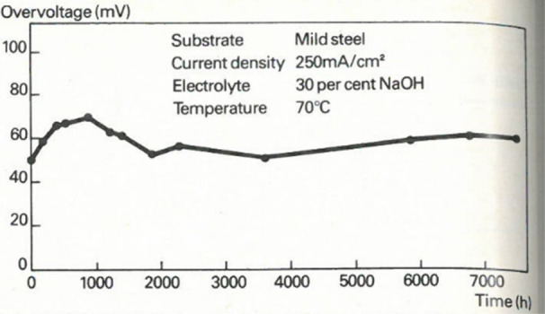
A chronopotentiometric measurement of NixMoy coated mild steel in 30 wt % NaOH at 250 mA/cm2 run for 7500 h showcasing long-term activity toward HER for the treated catalysts. Figure reproduced with permission from ref (430). Copyright 1984 John Wiley and Sons.
A variety of synthesis methods to produce NixMoy catalysts of different compositions exists with notable methods including ball-milling metal powders,431 electrodeposition,432 incorporation of Mo in Raney-Ni,432 and self-templating hydrothermal reaction.433−437
To date, the active site of NixMoy catalysts remains largely elusive, which is part of a continued debate about the intrinsic activity enhanced of NixMoy versus pure Ni.438 These discussions likely stem from the observation that many NixMoy synthesis methods generate very high surface areas, complicating the differentiation between improvements in intrinsic catalytic activity and those arising from a higher density of active sites. As an example, Zu et al. directly grew NiMo2 on high surface area porous carbon nanorods, and reported an η10 of 179 mV with a catalyst loading of 0.50 mg cm–2 and an ECSA of 11.2 mF cm–2.439 Indeed, most enhancements in NixMoy overpotential are likely attributable to an increased surface area, achieved either through higher catalyst loadings or synthesis optimizations that yield a higher density of material on the electrode surface.
Schalenbach et al. attempted to address this experimental issue by comparing arc-melted samples of Ni, Mo, NiMo, Ni2Mo, Ni3Mo, Ni4Mo, and Ni6Mo, with identical electrochemical surface areas, concluding that the activity benefits of alloying Ni with Mo are indeed limited.147 Conversely, results from McKone et al. show, on a mass-specific basis, that NixMoy nanopowders are, in fact, more active per surface atom than their pure Ni counterparts.440 Moreover, Schiller et al. found that by integrating Mo into a Raney Ni framework, the overpotential was substantially reduced, from 134 mV to 60 mV, at a current density of 1000 mA cm–2geo at 70 °C in 25 wt % KOH.441
To examine the trends between overpotential and surface roughness, Gellrich plotted η10 against surface roughness factor for various NixMoy and Ni electrodes, as shown in Figure 23. The data clearly show an improvement of the overpotential from alloying Mo with Ni, even for high surface area Ni catalysts.442
Figure 23.

Plot of NixMoy and Ni overpotentials versus their ECSA divided by the electrode geometric area. The green and red lines and shaded areas are semilogarithmic fits of the activity versus surface roughness factor and the 95% confidence interval, illustrating that data from the literature also indicate that NixMoy is intrinsically more active than Ni. Figure reproduced with permission from ref (442). Copyright 2021 F Gellrich at the Technical University of Denmark.
Doping NixMoy materials is another route toward lower overpotentials. Zhang et al. reacted NiMo with nitrogen using a N2 plasma, a technique that facilitated rapid, low-temperature manipulation of the d-band and significantly increased the catalyst’s surface area. This was also proposed to improve mass transport, the catalyst’s adhesion to the substrate, and its conductivity.443 Xiong et al. demonstrated that NiMoO4 and MoO2 from a hydrothermal reaction subsequently doped with phosphorus increased the electrochemical surface area and reduced the potential of the electrode compared to the same electrode without P-doping.444
An alternative approach to improve the apparent electrode overpotential of a NiMo-treated electrode has demonstrated by Patil et al., who improved the catalyst layer’s conductivity by incorporating carbon black, up to 50 wt %, amplifying both the geometric and mass activities of the NiMo electrode for HER 5-fold.445 Their results suggests that a promising avenue for enhancing NixMoy performance could be to increase the conductivity of the catalyst layer.
The Pourbaix diagram for molybdenum (Figure 20) clearly shows that pure molybdenum lacks stability under highly alkaline conditions (specifically, pH 13 and above) for the HER. While alloying with nickel offers some degree of stabilization, computational analyses reveal that this stabilizing effect is relatively modest, amounting to only a small shift of 0.12 eV. The same calculations indicate that Ni4Mo lacks thermodynamic stability above −100 mV versus RHE.152 Schalenbach et al. conducted pivotal experimental work on the stability of Mo, NiMo, Ni2Mo, Ni3Mo, Ni4Mo, and Ni6Mo, using in-line scanning flow-cell ICP-MS setup.147 They studied the catalysts in two distinct potential windows; −300 mV vs RHE and up to +400 mV vs RHE finding that Mo begins to leach above −150 mV vs RHE at room temperature (Figure 24). These experiments demonstrate that NixMoy catalysts will leach during intermittent operation, if the electrodes go to OCP, unless preventative measures are deployed.
Figure 24.

Mo dissolution from different NixMoy samples in 0.05 M NaOH measured using a scanning flow cell coupled to an ICP-MS. Below the dissolution graphs, the operational pattern is shown. A constant operation step at −200 mV vs RHE is followed by two triangular wave cyclic voltammetry measurements at 2 mV/s and finally the open circuit potential is measured for 500 s. All samples show Mo leaching. Reproduced with permission from ref (147). Copyright 2017 Elsevier.
Despite the lack of stability for NixMoy catalysts above −150 mV vs RHE (Figure 24), studies have demonstrated that improved overpotentials are observed and sustained even during intermittent operation, which may seem to contradict the stability measurements. However, where Schalenbach et al. focused on leaching during an experiment with high control of variable, the experiments claiming stability are based in the continued low overpotentials, without quantification of dissolved products or electrochemically active surface area. Nevertheless, the very long experiments show continued activity toward HER in industrially relevant test conditions and -setups. For example, in a study by Mahmood et al. in 1984, NixMoy dip-coated electrodes were evaluated in terms of their resistance to electrolyzer stack off-periods resembling electricity blackouts and scheduled maintenance.430 The overpotential was measured over an 1100-h chronopotentiometry test, with a one-, two-, and three-day off-period during the experiment. During the off-periods, the anode and cathode terminals were short-circuited, which likely induced reverse current flow. Their data concluded enhanced activity was sustained even after long periods in the dissolving potential regime. In another study, Raj et al. conducted accelerated degradation tests, which involved running multiple slow CVs at 0.5 mV s–1 between −100 mV and 200 mV vs RHE, and found sustained activity of the NiMo samples.446 A noteworthy experiment in 1998 involved operating a model A-WE electrolyzer for 15,000 h under various operation patterns, using Mo-doped Raney Ni cathodes. Interestingly, the total cell voltage decreased–likely due to leaching or uptake of metal impurities–over this duration, suggesting that the functional stability of NiMo may be sufficient for specific application schemes.447
Importantly, the majority of published studies base their assessment of catalyst stability on the measured overpotential or cell voltage over time, and if these stay constant or improve, the NixMoy electrodes are declared stable. Unfortunately, this is insufficient evidence of catalyst stability, although it does provide some merit to the discussion on the possibility of implementing NixMoy for industrial use. Despite the instability of NixMoy subjected to potentials above −150 mV vs RHE, it can still be feasible to create electrodes with sufficiently high loadings to allow for long-term stability. Higher loadings have the added benefit of likely lowering the initial overpotential of the catalyst, as shown in Figure 25.440
Figure 25.
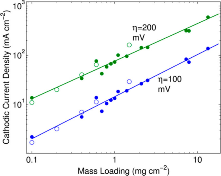
Current density at −100 mV and −200 mV vs RHE for Ti substrates coated with a range of mass loadings of Ni–Mo nanopowder in 2 M KOH. Open and closed circles represent data from two different sets of electrodes. Reproduced with permission from ref (440). Copyright 2012 American Chemical Society.
Despite the significant interest in NixMoy, controversy remains regarding the intrinsic activity of this catalyst family. The electrochemical stability of NixMoy electrodes also remains undeniably flawed, and the continuously record-breaking overpotentials are predominantly based on enhanced electrode surface areas and higher catalyst loadings. However, NixMoy compounds do consistently outperform other high-surface area Ni electrodes, excelling in activity and operational longevity.83 For continued NixMoy electrode development, overpotential reductions may be achieved by improving the catalyst layer’s conductivity. Furthermore, a clearer understanding of the relationship between synthesis parameters, loading, and electrode lifetime is needed.
3.4.2. Phosphides
As discussed previously (Section 3.3.2.), the field of transition metal phosphides for the HER began with studies of phosphides in alkaline electrolyte. Inspired by Budniok’s work on NiP and CoP catalysts in 5 M KOH for isobutyl alcohol oxidation,448 Paseka in 1995,449 and Shervedani and Lasia in 1997,379 synthesized metal phosphides as an alternative to the well-established NiS catalysts already in use for alkaline HER. More than a decade later, Liu and Rodriguez’s DFT study reignited the interest in the field,380 although their findings better apply to acidic electrolytes as is also described in Section 3.3.2.428
Popczun et al. verified the predicted high HER activity of Ni2P in both acidic and alkaline electrolytes but also noted that the catalyst degraded rapidly in 1 M KOH.381 Feng and his colleagues later corroborated the issue with phosphide stability in alkaline electrolytes.450 They conducted a 48-h chronoamperometry experiment and observed that the current density of the Ni2P catalysts halved. Other researchers have reported semistable CP data on Ni2P and NiP2 electrodes for alkaline HER despite the early discouraging results.451,452 For example, Laursen et al. reported that the η10 remained between 24–28 mV vs RHE for 16 h for the Ni5P4 catalyst during a chronopotentiometry measurement in 1 M NaOH. Moreover, ex situ ICP measurements, as shown in Figure 26, showed no Ni-dissolution, even with a substantial catalyst loading of 177 mg cm–2.386 These stability findings are supported by other research groups.453,454 Ledendecker et al. also investigated the stability of Ni5P4 but conversely find a decline in activity (of almost 60%) during a 20-h constant potential measurement.455
Figure 26.

Leached Ni during chronopotentiometric analyses of Ni2P in 1 M H2SO4 and Ni5P4 in 1 M H2SO4 and 1 M NaOH. The measurement shows that Ni does not leach from the Ni5P4 in alkaline solutions. Reproduced with permission from ref (386). Copyright 2015 Royal Society of Chemistry.
The research into transition metal phosphides for alkaline electrolytes has since then mainly focused on Ni, Mo, and Co and combinations thereof. A range of compositions have been tested, most of which have highlighted severe stability issues when assessed with CP and CA experiments. Some of the most notable examples are highlighted below.
MoP was studied by Xiao et al., where, during a 40-h chronopotentiometry experiment, they observed a 60% reduction in activity.389 In contrast, a MoP/Ni2P composite on nickel foam reported by Du et al. demonstrated a greater level of stability, with only a 9% decline observed over a 24-h CP measurement.456
For CoP, one study showed >66% activity decay over 100 h, evidenced by CP and Tafel slopes.457 In another dedicated and thorough investigation into the stability of CoP, researchers found that phosphorus tends to leach more readily than cobalt, leading to the transformation of the CoP phase into Co(OH)2, resulting in an increased overpotential for the HER.135
Bimetallic phosphide compositions have also been tested for HER properties in alkaline conditions. Guan et al. investigated Mo-doped CoP prepared through a reaction of Co-based metal–organic framework (MOF) with Na2MoO4 salt via a wet-synthesis method followed by annealing in an inert atmosphere.458 This process yielded a high-surface area catalyst, demonstrating semistable cathode operation with a 3% difference between the initial and final current densities in a 20-h chronoamperometry measurement. High-surface area NiCoP was tested in 2019 by Pan et al.298 As mentioned in Section 3.3.2, they found that it exhibited good stability in 0.5 M H2SO4, However, in 1 M KOH, the catalyst’s activity dropped from 13 mA cm–2 at η100 to 5 mA cm–2 within 21 h. Liang et al. reported similar results in their study on NiCoP. Initially, they reported a η10 of 32 mV, but after a 24-h CP measurement, the η10 increased to 75 mV. This activity drop represents more than a 10-fold activity drop considering their tafel slope of 37 mV dec–1.459 Co0.59Fe0.41P nanocubes, while demonstrating improved stability, still exhibited an activity drop of 25–30% during a 16-h chronoamperometry measurement.460
Man et al. conducted experimental and theoretical investigations into doping iron, cobalt, manganese, and molybdenum into a Ni2P hexagonal close-packed crystal lattice. Given each metal has a unique d-band properties, this variance enabled the modulation of a range of the final catalysts’ characteristics, such as η10, Tafel slope, and mass activity. Co-doped Ni2P was predicted to be the most active species for AWE applications at high current densities and to have the highest alloying stabilization energy of the calculated compositions. Mo-doped Ni2P was predicted to the most active catalyst at low current densities, which was confirmed experimentally.461 As stated in other sections of this review, it is crucial to note that electrochemical methods such as CA, CP, and CV serve as the most effective initial method for evaluating the stability of a catalyst. However, best practice always requires quantification of the catalyst loading and utilizing ICP quantification to determine the levels of dissolved elements during stability tests. Such data provides the most reliable means for comparing various research studies and offer the most accurate evaluation of a catalyst’s overall lifespan in a constant operation scenario.
In summary, the majority of transition metal phosphides for alkaline HER are active, but not stable. It is interesting to note that compared to acidic electrolyte, under alkaline conditions intrinsic activity metrics (e.g., TOF) are less commonly reported. We recommend that the wider community change this, to ensure catalyst loading and intrinsic activity metrics are always reported. Based on the electrochemical data, the most promising transition metal phosphides in alkaline electrolyte appears to be Ni5P4. Other NixPy phases may prove alternative electrocatalysts candidates, while more research into MoCoP may also prove fruitful.
4. Outlook and Concluding Thoughts
Developing precious metal free HER catalyst has received significant attention from the academic community over the past decade. While there exist many different promising electrolyzer designs, this review focuses on precious metal free catalysts for low temperature water electrolyzers with potential relevance to the various commercial (PEM-WE and A-WE) and precommercial (AEM-WE) electrolyzer technologies. Accordingly, we focus on catalysts characterized in either acidic or alkaline electrolytes.
Various catalyst performance metrics are commonly used to assess and compare catalyst activity and stability for the HER. We find that there have been numerous best practices, editorials and perspectives published for half-cell 3-electrode measurements for the HER, with guidance published on many experimental factors ranging from the choice of electrochemical cell (glass, polymeric etc.), electrolyte, electrode selection (e.g., reference and counter electrodes), cell configurations and electrochemical measurement protocols (e.g., iR correction, electrochemical stability measurements). We note that papers are regularly published which do not follow these recommended best-practices. We highly recommend that the community reconsider their experimental design to align with these recommendations. Activity is commonly reported through geometric activity metrics (e.g., overpotential required for a catalyst to generate 10 mA cm–2geo). We note that throughout the HER literature, the mass loading of the catalyst on the working electrode is often not measured or reported properly, rendering the work highly speculative with regards to assessing differences between catalyst electrodes. We strongly recommend that the field makes every effort to assess catalyst loadings and report HER catalysts with electrochemical surface area normalized currents, mass activities and turnover frequencies. Looking forward, the intrinsic activities of HER catalysts (in one form or another) should become the central metric for comparing precious metal free catalysts.
Beyond assessing catalyst activity, electrocatalyst stability is also essential for commercial deployment. Given the numerous mechanisms by which an HER catalyst can degrade, various electrochemical measurements (typically for a few hours only) are often deployed. Such studies are typically insufficient yet frequently lead to claims of a “highly stable” catalyst. When we consider the aspects of stability, it becomes clear that there is not a one-size-fits-all approach that can describe all scenarios, from RDE-scale measurements to electrolyzer stack applications. Therefore, the type of stability studies conducted, and resultant stability claims should be clearly labeled and put into context with the literature to better clarify the prudent conclusions arising from the selected measurement type. Furthermore, given the absence of literature studies which systematically and quantitively compare the various techniques used to probe stability (e.g., CP, CA, LSVs, etc.) across a series of catalysts the community should consider undertaking such studies to enable recommendations of which technique are superior for describing durability.
Recently, some stability measurements have been coupled to ICP measurements. ICP enables quantification of catalyst dissolution and is commonly deployed through ex situ measurements of the electrolyte. While in situ measurements require complex and expensive dedicated setups, when designed effectively, they can offer significant and critical insight regarding catalyst stability. From such studies, it is clear that precious metal free HER catalysts are particularly prone to dissolution at open circuit voltage, rather than while under reducing potentials (turning over the HER). To reliably examine catalyst dissolution alone, however, we need to take into consideration the factors that may influence the catalyst dissolution measurement. The factors range from catalyst to ionomer ratios, the introduction of catalysts into the electrolyte under potential control, and the electrolyte volume used in the electrochemical cell. Furthermore, the electrochemical cell design deployed for ICP dissolution studies requires careful attention to ensure it can mimic conditions in commercial electrolyzers. For this purpose, a systematic benchmarking exercise to quantify the effect of each of these experimental factors on catalyst activity and catalyst dissolution would be helpful. In summary, assessing an electrocatalyst stability is a complex and challenging undertaking, but efforts must be made to enable more insightful comparisons between different catalysts.
Throughout the precious metal free HER literature, we frequently encounter reports that do not follow most up to date published best practices with regards to the electrochemical setup. We encourage the community to periodically review their standard operating protocols to incorporate the latest adjustments within the field. For example, usage of Pt counter electrodes was ubiquitous early on. The observation that Pt from a counter electrode can migrate to the working electrode led to separation of counter and working electrode compartments and eventually to additionally replace the counter electrodes with graphitic carbons. Specific recommendations are now clearly rationalized for nearly every component of the 3-electrode electrochemical measurements for HER, covering reference electrodes, electrolyte choice, cell design etc.
Across the precious metal free HER catalysis literature, the overwhelming majority of HER studies are tested in a 3-electrode lab-scale half-cell configuration, which enables a relatively simple, rapid, convenient and cost-effective platform for the study of the fundamental properties of HER catalysts. Device testing (e.g., MEAs or A-WE), however, represents a critical experimental platform to enable assessment of the translatability of developed catalysts into electrolyzer technologies. The low rates of translation from half-cell to device is understandable, as the industrially relevant cell environment is notably harsher, often featuring higher electrolyte concentrations, higher current measurements, elevated temperatures, and increased gas pressures. Consequently, it is experimentally and financially challenging to emulate these conditions in academic settings, necessitating certain simplifications and compromises. While we do not consider it possible (or appropriate) for all research groups to translate catalysts into working 2-electrode device testing, a clear recommendation is that the research community who do work with such devices standardize their testing protocols as far as possible. For example, during MEA investigations aiming to understand the translatability of HER catalysts into devices, where possible, all components beyond the cathode are purchased as half MEAs from commercial suppliers. Such practices will facilitate a true comparison between different HER catalysts, rather than differences owing to membrane thickness, catalyst deposition methods, or ink formulations etc from other components than cathode catalyst layers. Additionally, there are numerous critical investigations yet to be undertaken, even for the most frequently reported HER catalysts such as MoS2, Mo2C, and CoP, which would enable assessment of the translatability of precious metal free catalyst to device deployment. For example, studies investigating the role of catalyst loadings, ink formulations, deposition methods, etc. on the performance of an electrolyzer with PGM free HER catalyst as the cathode electrode.
Numerous different catalysts and catalyst structures have been synthesized and characterized for the HER. The structures were derived via various design strategies including nanostructuring, binder-free or self-supported architectures, catalyst–supports, spatial confinement, encapsulated catalysts, single atom catalysts, heterostructured catalysts, and defect engineering. We conclude that the primary objective of such catalyst designs is to boost the catalyst performance through enhancing one of the following: the density of active sites on the catalyst surface, the intrinsic activity of the catalyst, catalyst stability, and/or through improvements in the catalyst (or catalyst layer) conductivity. We recommend that the community should seek careful design of control samples when seeking to claim enhanced HER activity or stability to ensure such catalyst designs are reported appropriately and accurately.
With regards to HER material choice, we highlight that nearly the entire periodic table has been explored in some capacity as an electrocatalyst for the HER. To assess the progress within the field, we focus our review on transition metal sulfides, phosphides and carbides as precious metal free HER catalysts in acidic electrolyte. In alkaline electrolyte we focus on NixMoy and transition metal phosphides. To explore activity trends across precious metal free HER catalysts, we collated a large set of published activity data for the sulfides, phosphides and carbides in acidic electrolyte. It is clear from these data that some materials can reach high geometric activities. However, when activity is normalized by catalyst loading (mass activities) the vast majority of geometric activity improvements are evidently due to increased catalyst loading, rather than any improvement to the intrinsic activity of the precious metal free catalysts. Indeed, when mass activities and turnover frequencies are compared to platinum-base catalysts, it is evident that precious metal free HER catalysts are significantly (3–4 orders of magnitude) inferior. We therefore recommend that future 3-electrode lab-scale testing emphasize mass activity or turnover frequency to benchmark the catalyst performance, rather than seeking higher geometric activities. Furthermore, across the HER literature (and more broadly electrocatalysis), we recommend that activity and stability metrics should include error bars, with average overpotentials with standard deviations used to compare series of catalysts.
Beyond the electrolyzer technologies discussed in this review (A-WE, PEM-WE, and AEM-WE) there remain a wealth of potential alternate applications and opportunities for the precious metal free HER catalysis community. For example, SO-WE technology is on the verge of commercialization. Also undoubtably, commercial electrolyzers of the future may have entirely different cell designs to those deployed today, expanding the operating window with regards to pH. Furthermore, recent literature has highlighted interest in seawater electrolysis, and unprocessed (nondeionized) water feeds may also become important in electrolysis. Hence, the need to quantify, develop and benchmark HER catalyst performance with typical water impurities may indeed prove critical. There are also potential opportunities for the HER beyond water splitting, e.g., through tandem catalysis for electrochemical hydrogenation of CO2 or coupling to an electro-organic oxidation reaction. Looking forward, we encourage continued innovations beyond the scope set out in this review and encourage the community to seek alternative materials and designs that may not be suitable for what is considered state-of-the-art technology currently. However, we remind the community to also ensure that they provide an honest assessment of the activity and stability of the catalyst to enable true comparison to state-of-the-art catalysts; this is essential whether the work is motivated by developing fundamental understanding, new electrolyzer designs, utilizing seawater or developing alternative applications of HER catalysts beyond the water splitting.
Acknowledgments
A.A.F. and J.K. acknowledge funding from Innovation Fund Denmark (IFD) under File No. 1044-00162B. C.W. and J.K. acknowledge funding by Villum Fonden, part of the Villum Center for the Science of Sustainable Fuels and Chemicals (V-SUSTAIN grant 9455). J.K. acknowledge funding from the Pioneer Center for Accelerating P2X Materials Discovery (CAPeX), DNRF grant number P3. D.X., Y.N.R., and L.A.K. are grateful for support from the Catalyst Hub funded by Engineering and Physical Sciences Research Council grant reference EP/R026645/1. L.A.K. also acknowledges the support from the Engineering and Physical Sciences Research Council EP/X009734/1.
Biographies
Anders A. Feidenhans’l is pursuing his Ph.D. in Physics at the Technical University of Denmark’s Center for Surface Physics & Catalysis. Prior to this, he delved into single-crystal X-ray scattering at Aarhus University’s Department of Chemistry under Bo Brummerstedt Iversen. His current research focuses on the causes of degradation of catalytically coated electrodes for the hydrogen evolution reaction. He seeks solutions to enhance their longevity in conditions resembling those in industrial water electrolyzers.
Yagya N. Regmi is a research fellow at Manchester Metropolitan University (MMU), U.K. leading work on renewable energy conversion and storage at the Manchester Fuel Cell Innovation Centre. He joined MMU after spending two years (2018–2019) at Lawrence Berkeley National Laboratories, first as a postdoctoral researcher and then as Project Engineer. Yagya received his Ph.D. in inorganic chemistry at the University of Wyoming (2015) and worked as a postdoctoral researcher at the Centre for Renewable Carbon, University of Tennessee (2016–2017).
Chao Wei is a postdoc, in Department of Physics at Technical University of Denmark (DTU). He started working in DTU since 2021, after a postdoc position in School of Materials Science and Engineering (MSE) at Nanyang Technological University (NTU), Singapore. Chao obtained his Ph.D. (2016) from MSE at NTU. His research focuses on electrochemical water splitting.
Dong Xia received his Ph.D. degree from University of Leeds in 2020. He then joined the National Institute for Materials Science in Japan as a postdoctoral fellow focusing on electrocatalytic hydrogen production (2022). Currently, he is a joint postdoctoral research associate at Manchester Metropolitan University and Oxford University exploring the electrochemical carbon dioxide reduction.
Jakob Kibsgaard is a Professor of Physics at the Technical University of Denmark (DTU). He joined DTU in 2016 after a position as associate staff scientist at SLAC National Accelerator Laboratory and Stanford University, USA, where he spent a total of six years. He received his M.Sc. in Material Physics-Chemistry (2006) and Ph.D. (2008) in Physics and Nanoscience from Aarhus University, Denmark. His research focuses on the development and understanding of thermal and electro-catalysts for sustainable energy conversion.
Laurie A. King is a Professor of Materials Chemistry at Manchester Metropolitan University, U.K. where she works within the Manchester Fuel Cell Innovation Centre leading a research group focused on the design and development of economic and sustainable electrocatalysts for energy technologies. Prior to her current position, she worked as a Research Engineer (2015–2017) and postdoctoral researcher (2015–2017) at the SUNCAT Research Centre at Stanford University, USA. Laurie also spent 2 years as a postdoctoral researcher at the University of Wyoming, after completing her Ph.D. in Materials Chemistry at Imperial College London (2013).
Supporting Information Available
The Supporting Information is available free of charge at https://pubs.acs.org/doi/10.1021/acs.chemrev.3c00712.
The authors declare no competing financial interest.
Special Issue
Published as part of Chemical Reviewsvirtual special issue “Green Hydrogen”.
Supplementary Material
References
- Capurso T.; Stefanizzi M.; Torresi M.; Camporeale S. M. Perspective of the Role of Hydrogen in the 21st Century Energy Transition. Energy Conv. and Manag. 2022, 251, 114898. 10.1016/j.enconman.2021.114898. [DOI] [Google Scholar]
- Falcone P. M.; Hiete M.; Sapio A. Hydrogen Economy and Sustainable Development Goals: Review and Policy Insights. Curr. Opin. Green Sustain. Chem. 2021, 31, 100506. 10.1016/j.cogsc.2021.100506. [DOI] [Google Scholar]
- Zhu J.; Hu L.; Zhao P.; Lee L. Y. S.; Wong K. Y. Recent Advances in Electrocatalytic Hydrogen Evolution Using Nanoparticles. Chem. Rev. 2020, 120 (2), 851–918. 10.1021/acs.chemrev.9b00248. [DOI] [PubMed] [Google Scholar]
- Global Hydrogen Review 2022; IEA, 2022.
- Ayers K. High Efficiency PEM Water Electrolysis: Enabled by Advanced Catalysts, Membranes, and Processes. Curr. Opin. Chem. Eng. 2021, 33, 100719. 10.1016/j.coche.2021.100719. [DOI] [Google Scholar]
- Ayers K.; Danilovic N.; Ouimet R.; Carmo M.; Pivovar B.; Bornstein M. Perspectives on Low-Temperature Electrolysis and Potential for Renewable Hydrogen at Scale. Annu. Rev. Chem. Biomol. Eng. 2019, 10, 219–39. 10.1146/annurev-chembioeng-060718-030241. [DOI] [PubMed] [Google Scholar]
- GREEN HYDROGEN COST REDUCTION SCALING UP ELECTROLYSERS TO MEET THE 1.5 °C CLIMATE GOAL; IRENA, 2020.
- Malkow T.; Pilenga A.; Tsotridis G.. EU Harmonised Test Procedure : Electrochemical Impedance Spectroscopy for Water Electrolysis Cells; European Commission, 2018. [Google Scholar]
- Hydrogen Insights 2023, An Update on the State of the Global Hydrogen Economy, with a Deep Dive into North America; Hydrogen Council, 2023.
- Falcão D. S. Green Hydrogen Production by Anion Exchange Membrane Water Electrolysis: Status and Future Perspectives. Energies 2023, 16 (2), 1–8. 10.3390/en16020943. [DOI] [Google Scholar]
- Du N.; Roy C.; Peach R.; Turnbull M.; Thiele S.; Bock C. Anion-Exchange Membrane Water Electrolyzers. Chem. Rev. 2022, 122 (13), 11830–11895. 10.1021/acs.chemrev.1c00854. [DOI] [PMC free article] [PubMed] [Google Scholar]
- Miller H. A.; Bouzek K.; Hnat J.; Loos S.; Bernäcker C. I.; Weißgärber T.; Röntzsch L.; Meier-Haack J. Green Hydrogen from Anion Exchange Membrane Water Electrolysis: A Review of Recent Developments in Critical Materials and Operating Conditions. Sustain. Energy Fuels. 2020, 4 (5), 2114–2133. 10.1039/C9SE01240K. [DOI] [Google Scholar]
- Tian Y.; Abhishek N.; Yang C.; Yang R.; Choi S.; Chi B.; Pu J.; Ling Y.; Irvine J. T. S.; Kim G. Progress and Potential for Symmetrical Solid Oxide Electrolysis Cells. Matter. 2022, 5, 482–514. 10.1016/j.matt.2021.11.013. [DOI] [Google Scholar]
- Wang L.; Chen M.; Küngas R.; Lin T. E.; Diethelm S.; Maréchal F.; Van herle J. Power-to-Fuels via Solid-Oxide Electrolyzer: Operating Window and Techno-Economics. Renewable Sustainable Energy Rev. 2019, 110, 174–187. 10.1016/j.rser.2019.04.071. [DOI] [Google Scholar]
- Hauch A.; Küngas R.; Blennow P.; Hansen A. B.; Hansen J. B.; Mathiesen B. V.; Mogensen M. B.. Recent Advances in Solid Oxide Cell Technology for Electrolysis. Science 2020, 370 ( (6513), ). 10.1126/science.aba6118 [DOI] [PubMed] [Google Scholar]
- Shiva Kumar S.; Lim H. An Overview of Water Electrolysis Technologies for Green Hydrogen Production. Energy Rep. 2022, 8, 13793–13813. 10.1016/j.egyr.2022.10.127. [DOI] [Google Scholar]
- Hancke R.; Holm T.; Ulleberg Ø. The Case for High-Pressure PEM Water Electrolysis. Energy Convers. Manag. 2022, 261, 115642. 10.1016/j.enconman.2022.115642. [DOI] [Google Scholar]
- Trinke P.; Haug P.; Brauns J.; Bensmann B.; Hanke-Rauschenbach R.; Turek T. Hydrogen Crossover in PEM and Alkaline Water Electrolysis: Mechanisms, Direct Comparison and Mitigation Strategies. J. Electrochem. Soc. 2018, 165 (7), F502–F513. 10.1149/2.0541807jes. [DOI] [Google Scholar]
- Brauns J.; Turek T. Alkaline Water Electrolysis Powered by Renewable Energy: A Review. Processes. 2020, 8 (2), 248. 10.3390/pr8020248. [DOI] [Google Scholar]
- Yu Z. Y.; Duan Y.; Feng X. Y.; Yu X.; Gao M. R.; Yu S. H. Clean and Affordable Hydrogen Fuel from Alkaline Water Splitting: Past, Recent Progress, and Future Prospects. Adv. Mater. 2021, 33 (31), 1–35. 10.1002/adma.202007100. [DOI] [PubMed] [Google Scholar]
- Ehlers J. C.; Feidenhans’l A. A.; Therkildsen K. T.; Larrazábal G. O. Affordable Green Hydrogen from Alkaline Water Electrolysis: Key Research Needs from an Industrial Perspective. ACS Energy Lett. 2023, 8 (3), 1502–1509. 10.1021/acsenergylett.2c02897. [DOI] [Google Scholar]
- Carmo M.; Fritz D. L.; Mergel J.; Stolten D. A Comprehensive Review on PEM Water Electrolysis. Int. J. Hydrog. Energy. 2013, 38 (12), 4901–4934. 10.1016/j.ijhydene.2013.01.151. [DOI] [Google Scholar]
- Aricò A. S.; Siracusano S.; Briguglio N.; Baglio V.; Blasi A.; Antonucci V. Polymer Electrolyte Membrane Water Electrolysis: Status of Technologies and Potential Applications in Combination with Renewable Power Sources. J. Appl. Electrochem. 2013, 43 (2), 107–118. 10.1007/s10800-012-0490-5. [DOI] [Google Scholar]
- Ayers K.; Danilovic N.; Harrison K.; Hui X. PEM Electrolysis, a Forerunner for Clean Hydrogen. Electrochem. Soc. Interface. 2021, 30, 67–71. 10.1149/2.F16214IF. [DOI] [Google Scholar]
- Kusoglu A.; Weber A. Z. New Insights into Perfluorinated Sulfonic-Acid Ionomers. Chem. Rev. 2017, 117 (3), 987–1104. 10.1021/acs.chemrev.6b00159. [DOI] [PubMed] [Google Scholar]
- Phillips R.; Dunnill C. W. Zero Gap Alkaline Electrolysis Cell Design for Renewable Energy Storage as Hydrogen Gas. RSC Adv. 2016, 6 (102), 100643–100651. 10.1039/C6RA22242K. [DOI] [Google Scholar]
- Li D.; Motz A. R.; Bae C.; Fujimoto C.; Yang G.; Zhang F. Y.; Ayers K. E.; Kim Y. S. Durability of Anion Exchange Membrane Water Electrolyzers. Energy Environ. Sci. 2021, 14 (6), 3393–3419. 10.1039/D0EE04086J. [DOI] [Google Scholar]
- Wu X.; Hu X. Anion Exchange Membranes for Hydrogen Technologies: Challenges and Progress. Chimia (Aarau). 2023, 77, 494. 10.2533/chimia.2023.494. [DOI] [PubMed] [Google Scholar]
- Xiao L.; Zhang S.; Pan J.; Yang C.; He M.; Zhuang L.; Lu J. First Implementation of Alkaline Polymer Electrolyte Water Electrolysis Working Only with Pure Water. Energy Environ. Sci. 2012, 5 (7), 7869–7871. 10.1039/c2ee22146b. [DOI] [Google Scholar]
- Segev G.; Kibsgaard J.; Hahn C.; Xu Z. J.; Cheng W. H.; Deutsch T. G.; Xiang C.; Zhang J. Z.; Hammarström L.; Nocera D. G. The 2022 Solar Fuels Roadmap. J. Phys. D. Appl. Phys. 2022, 55 (32), 323003. 10.1088/1361-6463/ac6f97. [DOI] [Google Scholar]
- Santoro C.; Lavacchi A.; Mustarelli P.; Di Noto V.; Elbaz L.; Dekel D. R.; Jaouen F. What Is Next in Anion-Exchange Membrane Water Electrolyzers? Bottlenecks, Benefits, and Future. ChemSusChem. 2022, 15, e202200027 10.1002/cssc.202200027. [DOI] [PMC free article] [PubMed] [Google Scholar]
- Hodges A.; Hoang A. L.; Tsekouras G.; Wagner K.; Lee C. Y.; Swiegers G. F.; Wallace G. G. A High-Performance Capillary-Fed Electrolysis Cell Promises More Cost-Competitive Renewable Hydrogen. Nat. Commun. 2022, 13 (1), 1–11. 10.1038/s41467-022-28953-x. [DOI] [PMC free article] [PubMed] [Google Scholar]
- O’Neil G. D.; Christian C. D.; Brown D. E.; Esposito D. V. Hydrogen Production with a Simple and Scalable Membraneless Electrolyzer. J. Electrochem. Soc. 2016, 163 (11), F3012–F3019. 10.1149/2.0021611jes. [DOI] [Google Scholar]
- Davis J. T.; Qi J.; Fan X.; Bui J. C.; Esposito D. V. Floating Membraneless PV-Electrolyzer Based on Buoyancy-Driven Product Separation. Int. J. Hydrog. Energy. 2018, 43 (3), 1224–1238. 10.1016/j.ijhydene.2017.11.086. [DOI] [Google Scholar]
- Hashemi S. M. H.; Karnakov P.; Hadikhani P.; Chinello E.; Litvinov S.; Moser C.; Koumoutsakos P.; Psaltis D. A Versatile and Membrane-Less Electrochemical Reactor for the Electrolysis of Water and Brine. Energy Environ. Sci. 2019, 12 (5), 1592–1604. 10.1039/C9EE00219G. [DOI] [Google Scholar]
- Esposito D. V. Membraneless Electrolyzers for Low-Cost Hydrogen Production in a Renewable Energy Future. Joule. 2017, 1 (4), 651–658. 10.1016/j.joule.2017.07.003. [DOI] [Google Scholar]
- Rausch B.; Symes M. D.; Chisholm G.; Cronin L. Decoupled Catalytic Hydrogen Evolution from a Molecular Metal Oxide Redox Mediator in Water Splitting. Science. 2014, 345 (6202), 1326–1330. 10.1126/science.1257443. [DOI] [PubMed] [Google Scholar]
- Lagadec M. F.; Grimaud A. Water Electrolysers with Closed and Open Electrochemical Systems. Nat. Mater. 2020, 19 (11), 1140–1150. 10.1038/s41563-020-0788-3. [DOI] [PubMed] [Google Scholar]
- You B.; Sun Y. Innovative Strategies for Electrocatalytic Water Splitting. Acc. Chem. Res. 2018, 51 (7), 1571–1580. 10.1021/acs.accounts.8b00002. [DOI] [PubMed] [Google Scholar]
- Harrison K. W.; Remick R.; Martin G. D.; Hoskin A.. Hydrogen Production: Fundamentals and Case Study Summaries. Conference Paper NREL/CP-550-47302; NREL, 2010; Vol. 78, pp 207–226.
- Erdey-Grúz T.; Volmer M. Zur Theorie Der Wasserstoff Überspannung. Z. Phys. Chem. 1930, 150A (1), 203–213. 10.1515/zpch-1930-15020. [DOI] [Google Scholar]
- Trasatti S. Work Function, Electronegativity, and Electrochemical Behaviour of Metals. III. Electrolytic Hydrogen Evolution in Acid Solutions. J. Electroanal. Chem. 1972, 39 (1), 163–184. 10.1016/S0022-0728(72)80485-6. [DOI] [Google Scholar]
- Hu C.; Zhang L.; Gong J. Recent Progress Made in the Mechanism Comprehension and Design of Electrocatalysts for Alkaline Water Splitting. Energy Environ. Sci. 2019, 12 (9), 2620–2645. 10.1039/C9EE01202H. [DOI] [Google Scholar]
- Lasia A. Mechanism and Kinetics of the Hydrogen Evolution Reaction. Int. J. Hydrog. Energy. 2019, 44 (36), 19484–19518. 10.1016/j.ijhydene.2019.05.183. [DOI] [Google Scholar]
- Tian X.; Zhao P.; Sheng W. Hydrogen Evolution and Oxidation: Mechanistic Studies and Material Advances. Adv. Mater. 2019, 31, 1808066. 10.1002/adma.201808066. [DOI] [PubMed] [Google Scholar]
- Mahmood N.; Yao Y.; Zhang J.; Pan L.; Zhang X.; Zou J. Electrocatalysts for Hydrogen Evolution in Alkaline Electrolytes: Mechanisms, Challenges, and Prospective Solutions. Adv. Sci. 2018, 5, 1700464. 10.1002/advs.201700464. [DOI] [PMC free article] [PubMed] [Google Scholar]
- Zheng Y.; Jiao Y.; Vasileff A.; Qiao S. The Hydrogen Evolution Reaction in Alkaline Solution: From Theory, Single Crystal Models, to Practical Electrocatalysts. Angew. Chem., Int. Ed. Engl. 2018, 57 (26), 7568–7579. 10.1002/anie.201710556. [DOI] [PubMed] [Google Scholar]
- Seh Z. W.; Kibsgaard J.; Dickens C. F.; Chorkendorff I.; Nørskov J. K.; Jaramillo T. F.. Combining Theory and Experiment in Electrocatalysis: Insights into Materials Design. Science. 2017, 355 ( (6321), ). 10.1126/science.aad4998 [DOI] [PubMed] [Google Scholar]
- Kibsgaard J.; Chorkendorff I. Considerations for the Scaling-up of Water Splitting Catalysts. Nat. Energy. 2019, 4 (6), 430–433. 10.1038/s41560-019-0407-1. [DOI] [Google Scholar]
- Zheng Y.; Jiao Y.; Vasileff A.; Qiao S. The Hydrogen Evolution Reaction in Alkaline Solution: From Theory, Single Crystal Models, to Practical Electrocatalysts. Angew. Chem., Int. Ed. Engl. 2018, 57 (26), 7568–7579. 10.1002/anie.201710556. [DOI] [PubMed] [Google Scholar]
- Danilovic N.; Subbaraman R.; Strmcnik D.; Stamenkovic V.; Markovic N. Electrocatalysis of the HER in Acid and Alkaline Media. J. Serb. Chem. Soc. 2013, 78 (12), 2007–2015. 10.2298/JSC131118136D. [DOI] [Google Scholar]
- Hansen J. N.; Prats H.; Toudahl K. K.; Mørch Secher N.; Chan K.; Kibsgaard J.; Chorkendorff I. Is There Anything Better than Pt for HER?. ACS Energy Lett. 2021, 6 (4), 1175–1180. 10.1021/acsenergylett.1c00246. [DOI] [PMC free article] [PubMed] [Google Scholar]
- Zalitis C. M.; Kramer D.; Sharman J.; Wright E.; Kucernak A. R. Pt Nano-Particle Performance for PEFC Reactions At Low Catalyst Loading and High Reactant Mass Transport. ECS Meeting Abstracts MA 2013, 2 (15), 1247. 10.1149/MA2013-02/15/1247. [DOI] [Google Scholar]
- Morales-Guio C. G.; Stern L.-A.; Hu X. Nanostructured Hydrotreating Catalysts for Electrochemical Hydrogen Evolution. Chem. Soc. Rev. 2014, 43 (18), 6555–6569. 10.1039/C3CS60468C. [DOI] [PubMed] [Google Scholar]
- Dubouis N.; Grimaud A. The Hydrogen Evolution Reaction: From Material to Interfacial Descriptors. Chem. Sci. 2019, 10 (40), 9165–9181. 10.1039/C9SC03831K. [DOI] [PMC free article] [PubMed] [Google Scholar]
- Sheng W.; Gasteiger H. A.; Shao-Horn Y. Hydrogen Oxidation and Evolution Reaction Kinetics on Platinum: Acid vs Alkaline Electrolytes. J. Electrochem. Soc. 2010, 157 (11), 1529. 10.1149/1.3483106. [DOI] [Google Scholar]
- Durst J.; Siebel A.; Simon C.; Hasché F.; Herranz J.; Gasteiger H. A. New Insights into the Electrochemical Hydrogen Oxidation and Evolution Reaction Mechanism. Energy Environ. Sci. 2014, 7 (7), 2255–2260. 10.1039/C4EE00440J. [DOI] [Google Scholar]
- Rebollar L.; Intikhab S.; Oliveira N. J.; Yan Y.; Xu B.; McCrum I. T.; Snyder J. D.; Tang M. H. Beyond Adsorption” Descriptors in Hydrogen Electrocatalysis. ACS Catal. 2020, 10 (24), 14747–14762. 10.1021/acscatal.0c03801. [DOI] [Google Scholar]
- Parsons R. The Rate of Electrolytic Hydrogen Evolution and the Heat of Adsorption of Hydrogen. Trans. Faraday Soc. 1958, 54, 1053–1063. 10.1039/tf9585401053. [DOI] [Google Scholar]
- Skúlason E.; Tripkovic V.; Björketun M. E.; Gudmundsdóttir S.; Karlberg G.; Rossmeisl J.; Bligaard T.; Jónsson H.; Nørskov J. K. Modeling the Electrochemical Hydrogen Oxidation and Evolution Reactions on the Basis of Density Functional Theory Calculations. J. Phys. Chem. C 2010, 114 (42), 18182–18197. 10.1021/jp1048887. [DOI] [Google Scholar]
- Nørskov J. K.; Bligaard T.; Logadottir A.; Kitchin J. R.; Chen J. G.; Pandelov S.; Stimming U. Trends in the Exchange Current for Hydrogen Evolution. J. Electrochem. Soc. 2005, 152 (3), J23. 10.1149/1.1856988. [DOI] [Google Scholar]
- Greeley J.; Jaramillo T. F.; Bonde J.; Chorkendorff I.; Nørskov J. K. Computational High-Throughput Screening of Electrocatalytic Materials for Hydrogen Evolution. Nat. Mater. 2006, 5 (11), 909–913. 10.1038/nmat1752. [DOI] [PubMed] [Google Scholar]
- Laursen A. B.; Wexler R. B.; Whitaker M. J.; Izett E. J.; Calvinho K. U. D.; Hwang S.; Rucker R.; Wang H.; Li J.; Garfunkel E.; Greenblatt M.; et al. Climbing the Volcano of Electrocatalytic Activity While Avoiding Catalyst Corrosion: Ni3P, a Hydrogen Evolution Electrocatalyst Stable in Both Acid and Alkali. ACS Catal. 2018, 8 (5), 4408–4419. 10.1021/acscatal.7b04466. [DOI] [Google Scholar]
- Kibsgaard J.; Tsai C.; Chan K.; Benck J. D.; Nørskov J. K.; Abild-Pedersen F.; Jaramillo T. F. Designing an Improved Transition Metal Phosphide Catalyst for Hydrogen Evolution Using Experimental and Theoretical Trends. Energy Environ. Sci. 2015, 8 (10), 3022–3029. 10.1039/C5EE02179K. [DOI] [Google Scholar]
- Yu Y.; Zhou J.; Sun Z. Novel 2D Transition-Metal Carbides: Ultrahigh Performance Electrocatalysts for Overall Water Splitting and Oxygen Reduction. Adv. Funct. Mater. 2020, 30 (47), 1–9. 10.1002/adfm.202000570. [DOI] [Google Scholar]
- Zhang Q.; Jiang Z.; Tackett B. M.; Denny S. R.; Tian B.; Chen X.; Wang B.; Chen J. G. Trends and Descriptors of Metal-Modified Transition Metal Carbides for Hydrogen Evolution in Alkaline Electrolyte. ACS Catal. 2019, 9 (3), 2415–2422. 10.1021/acscatal.8b03990. [DOI] [Google Scholar]
- Seh Z. W.; Fredrickson K. D.; Anasori B.; Kibsgaard J.; Strickler A. L.; Lukatskaya M. R.; Gogotsi Y.; Jaramillo T. F.; Vojvodic A. Two-Dimensional Molybdenum Carbide (MXene) as an Efficient Electrocatalyst for Hydrogen Evolution. ACS Energy Lett. 2016, 1 (3), 589–594. 10.1021/acsenergylett.6b00247. [DOI] [Google Scholar]
- Abghoui Y.; Skúlason E. Hydrogen Evolution Reaction Catalyzed by Transition-Metal Nitrides. J. Phys. Chem. C 2017, 121 (43), 24036–24045. 10.1021/acs.jpcc.7b06811. [DOI] [Google Scholar]
- Kim J.; Jung H.; Jung S. M.; Hwang J.; Kim D. Y.; Lee N.; Kim K. S.; Kwon H.; Kim Y. T.; Han J. W.; Kim J. K. Tailoring Binding Abilities by Incorporating Oxophilic Transition Metals on 3D Nanostructured Ni Arrays for Accelerated Alkaline Hydrogen Evolution Reaction. J. Am. Chem. Soc. 2021, 143 (3), 1399–1408. 10.1021/jacs.0c10661. [DOI] [PubMed] [Google Scholar]
- Quaino P.; Juarez F.; Santos E.; Schmickler W. Volcano Plots in Hydrogen Electrocatalysis-Uses and Abuses. Beilstein J. Nanotechnol. 2014, 5 (1), 846–854. 10.3762/bjnano.5.96. [DOI] [PMC free article] [PubMed] [Google Scholar]
- Zhuang H.; Tkalych A. J.; Carter E. A. Surface Energy as a Descriptor of Catalytic Activity. J. Phys. Chem. C 2016, 120 (41), 23698–23706. 10.1021/acs.jpcc.6b09687. [DOI] [Google Scholar]
- Zeradjanin A. R.; Grote J. P.; Polymeros G.; Mayrhofer K. J. J. A Critical Review on Hydrogen Evolution Electrocatalysis: Re-Exploring the Volcano-Relationship. Electroanalysis. 2016, 28 (10), 2256–2269. 10.1002/elan.201600270. [DOI] [Google Scholar]
- Halck N. B.; Petrykin V.; Krtil P.; Rossmeisl J. Beyond the Volcano Limitations in Electrocatalysis-Oxygen Evolution Reaction. Phys. Chem. Chem. Phys. 2014, 16 (27), 13682–13688. 10.1039/C4CP00571F. [DOI] [PubMed] [Google Scholar]
- Exner K. S. Does a Thermoneutral Electrocatalyst Correspond to the Apex of a Volcano Plot for a Simple Two-Electron Process?. Angew. Chem., Int. Ed. Engl. 2020, 59 (26), 10236–10240. 10.1002/anie.202003688. [DOI] [PubMed] [Google Scholar]
- Ooka H.; Huang J.; Exner K. S. The Sabatier Principle in Electrocatalysis: Basics, Limitations, and Extensions. Front. Energy Res. 2021, 9, 654460. 10.3389/fenrg.2021.654460. [DOI] [Google Scholar]
- Lindgren P.; Kastlunger G.; Peterson A. A. A Challenge to the G ∼ 0 Interpretation of Hydrogen Evolution. ACS Catal. 2020, 10 (1), 121–128. 10.1021/acscatal.9b02799. [DOI] [Google Scholar]
- Kim J.; Jung H.; Jung S. M.; Hwang J.; Kim D. Y.; Lee N.; Kim K. S.; Kwon H.; Kim Y. T.; Han J. W.; Kim J. K. Tailoring Binding Abilities by Incorporating Oxophilic Transition Metals on 3D Nanostructured Ni Arrays for Accelerated Alkaline Hydrogen Evolution Reaction. J. Am. Chem. Soc. 2021, 143 (3), 1399–1408. 10.1021/jacs.0c10661. [DOI] [PubMed] [Google Scholar]
- Wei C.; Rao R. R.; Peng J.; Huang B.; Stephens I. E. L.; Risch M.; Xu Z. J.; Shao-Horn Y. Recommended Practices and Benchmark Activity for Hydrogen and Oxygen Electrocatalysis in Water Splitting and Fuel Cells. Adv. Mater. 2019, 31, e1806296 10.1002/adma.201806296. [DOI] [PubMed] [Google Scholar]
- Benck J. D.; Hellstern T. R.; Kibsgaard J.; Chakthranont P.; Jaramillo T. F. Catalyzing the Hydrogen Evolution Reaction (HER) with Molybdenum Sulfide Nanomaterials. ACS Catal. 2014, 4 (11), 3957–3971. 10.1021/cs500923c. [DOI] [Google Scholar]
- Anantharaj S.; Sagayaraj P. J. J.; Yesupatham M. S.; Arulraj R.; Eswaran K.; Sekar K.; Noda S. The Reference Electrode Dilemma in Energy Conversion Electrocatalysis: “Right vs. Okay vs. Wrong.. J. Mater. Chem. A 2023, 11, 17699–17709. 10.1039/D3TA03145D. [DOI] [Google Scholar]
- Anantharaj S.; Karthik P. E.; Noda S. The Significance of Properly Reporting Turnover Frequency in Electrocatalysis Research. Angew. Chem., Int. Ed. Engl. 2021, 60 (43), 23051–23067. 10.1002/anie.202110352. [DOI] [PMC free article] [PubMed] [Google Scholar]
- Anantharaj S.; Noda S.; Jothi V. R.; Yi S. C.; Driess M.; Menezes P. W. Strategies and Perspectives to Catch the Missing Pieces in Energy-Efficient Hydrogen Evolution Reaction in Alkaline Media. Angew. Chem., Int. Ed. Engl. 2021, 60 (35), 18981–19006. 10.1002/anie.202015738. [DOI] [PMC free article] [PubMed] [Google Scholar]
- McCrory C. C. L.; Jung S.; Ferrer I. M.; Chatman S. M.; Peters J. C.; Jaramillo T. F. Benchmarking Hydrogen Evolving Reaction and Oxygen Evolving Reaction Electrocatalysts for Solar Water Splitting Devices. J. Am. Chem. Soc. 2015, 137 (13), 4347–4357. 10.1021/ja510442p. [DOI] [PubMed] [Google Scholar]
- Callejas J. F.; Read C. G.; Roske C. W.; Lewis N. S.; Schaak R. E. Synthesis, Characterization, and Properties of Metal Phosphide Catalysts for the Hydrogen-Evolution Reaction. Chem. Mater. 2016, 28 (17), 6017–6044. 10.1021/acs.chemmater.6b02148. [DOI] [Google Scholar]
- Voiry D.; Chhowalla M.; Gogotsi Y.; Kotov N. A.; Li Y.; Penner R. M.; Schaak R. E.; Weiss P. S. Best Practices for Reporting Electrocatalytic Performance of Nanomaterials. ACS Nano 2018, 12 (10), 9635–9638. 10.1021/acsnano.8b07700. [DOI] [PubMed] [Google Scholar]
- Bernt M.; Gasteiger H. A. Influence of Ionomer Content in IrO2/TiO2 Electrodes on PEM Water Electrolyzer Performance. J. Electrochem. Soc. 2016, 163 (11), F3179–F3189. 10.1149/2.0231611jes. [DOI] [Google Scholar]
- Xu W.; Scott K. The Effects of Ionomer Content on PEM Water Electrolyser Membrane Electrode Assembly Performance. Int. J. Hydrog. Energy. 2010, 35 (21), 12029–12037. 10.1016/j.ijhydene.2010.08.055. [DOI] [Google Scholar]
- Xue Q.; Zhang R.; Yang D.; Li B.; Ming P.; Zhang C. Effect of Ionomer Content on Cathode Catalyst Layer for PEMFC via Molecular Dynamics Simulations and Experiments. Int. J. Hydrog. Energy. 2022, 47 (55), 23335–23347. 10.1016/j.ijhydene.2022.05.122. [DOI] [Google Scholar]
- Anantharaj S.; Noda S.; Driess M.; Menezes P. W. The Pitfalls of Using Potentiodynamic Polarization Curves for Tafel Analysis in Electrocatalytic Water Splitting. ACS Energy Lett. 2021, 6 (4), 1607–1611. 10.1021/acsenergylett.1c00608. [DOI] [Google Scholar]
- Anantharaj S.; Ede S. R.; Karthick K.; Sam Sankar S.; Sangeetha K.; Karthik P. E.; Kundu S. Precision and Correctness in the Evaluation of Electrocatalytic Water Splitting: Revisiting Activity Parameters with a Critical Assessment. Energy Environ. Sci. 2018, 11 (4), 744–771. 10.1039/C7EE03457A. [DOI] [Google Scholar]
- Chen J. G.; Jones C. W.; Linic S.; Stamenkovic V. R. Best Practices in Pursuit of Topics in Heterogeneous Electrocatalysis. ACS Catal. 2017, 7 (9), 6392–6393. 10.1021/acscatal.7b02839. [DOI] [Google Scholar]
- Galyamin D.; Torrero J.; Elliott J. D.; Rodríguez-García I.; Sánchez D. G.; Salam M. A.; Gago A. S.; Mokhtar M.; Gómez de la Fuente J. L.; Bueno S. V.; et al. Insights into the High Activity of Ruthenium Phosphide for the Production of Hydrogen in Proton Exchange Membrane Water Electrolyzers. Adv. Energy Sustainability Res. 2023, 4, 202300059. 10.1002/aesr.202300059. [DOI] [Google Scholar]
- Gileadi E.; Kirowa-Eisner E. Some Observations Concerning the Tafel Equation and Its Relevance to Charge Transfer in Corrosion. Corros. Sci. 2005, 47 (12), 3068–3085. 10.1016/j.corsci.2005.05.044. [DOI] [Google Scholar]
- Kichigin V. I.; Shein A. B. Diagnostic Criteria for Hydrogen Evolution Mechanisms in Electrochemical Impedance Spectroscopy. Electrochim. Acta 2014, 138, 325–333. 10.1016/j.electacta.2014.06.114. [DOI] [Google Scholar]
- Kibsgaard J.; Jaramillo T. F. Molybdenum Phosphosulfide: An Active, Acid-Stable, Earth-Abundant Catalyst for the Hydrogen Evolution Reaction. Angew. Chem., Int. Ed. Engl. 2014, 53 (52), 14433–14437. 10.1002/anie.201408222. [DOI] [PubMed] [Google Scholar]
- Myers D.; Alia S.; Mukundan R.. H2NEW Hydrogen (H2) from Next-Generation Electrolyzers of Water: H2NEW LTE: Durability and AST Development; U.S. Department of Energy, 2021.
- Alia S. M.; Reeves K. S.; Yu H.; Park J.; Kariuki N.; Kropf A. J.; Myers D. J.; Cullen D. A. Electrolyzer Performance Loss from Accelerated Stress Tests and Corresponding Changes to Catalyst Layers and Interfaces. J. Electrochem. Soc. 2022, 169 (5), 054517. 10.1149/1945-7111/ac697e. [DOI] [Google Scholar]
- Tsotridis G.; Pilenga A.. EU Harmonised Protocols for Testing of Low Temperature Water Electrolysers; EUR 30752 EN, Publications Office of the European Union 2021. [Google Scholar]
- Regmi Y. N.; Peng X.; Fornaciari J. C.; Wei M.; Myers D. J.; Weber A. Z.; Danilovic N. A Low Temperature Unitized Regenerative Fuel Cell Realizing 60% Round Trip Efficiency and 10 000 Cycles of Durability for Energy Storage Applications. Energy Environ. Sci. 2020, 13 (7), 2096–2105. 10.1039/C9EE03626A. [DOI] [Google Scholar]
- Alia S. M.; Danilovic N. Rotating Disk Electrode Standardization and Best Practices in Acidic Oxygen Evolution for Low-Temperature Electrolysis. Front. Energy Res. 2022, 10, 857663. 10.3389/fenrg.2022.857663. [DOI] [Google Scholar]
- Creel E. B.; Lyu X.; McCool G.; Ouimet R. J.; Serov A. Protocol for Screening Water Oxidation or Reduction Electrocatalyst Activity in a Three-Electrode Cell for Alkaline Exchange Membrane Electrolysis. Front. Energy Res. 2022, 10, 871604. 10.3389/fenrg.2022.871604. [DOI] [Google Scholar]
- Li D.; Batchelor-McAuley C.; Compton R. G. Some Thoughts about Reporting the Electrocatalytic Performance of Nanomaterials. Appl. Mater. Today. 2020, 18, 100404. 10.1016/j.apmt.2019.05.011. [DOI] [Google Scholar]
- Oshchepkov A. G. Critical Aspects in the Reliable Assessment of Activity Data for Electrocatalytic Materials. Curr. Opin. Electrochem. 2023, 39, 101266. 10.1016/j.coelec.2023.101266. [DOI] [Google Scholar]
- Dix S. T.; Lu S.; Linic S. Critical Practices in Rigorously Assessing the Inherent Activity of Nanoparticle Electrocatalysts. ACS Catal. 2020, 10 (18), 10735–10741. 10.1021/acscatal.0c03028. [DOI] [Google Scholar]
- Tiwari A.; Maagaard T.; Chorkendorff I.; Horch S. Effect of Dissolved Glassware on the Structure-Sensitive Part of the Cu(111) Voltammogram in KOH. ACS Energy Lett. 2019, 4 (7), 1645–1649. 10.1021/acsenergylett.9b01064. [DOI] [Google Scholar]
- Garsany Y.; Baturina O. A.; Swider-Lyons K. E.; Kocha S. S. Experimental Methods for Quantifying the Activity of Platinum Electrocatalysts for the Oxygen Reduction Reaction. Anal. Chem. 2010, 82 (15), 6321–6328. 10.1021/ac100306c. [DOI] [PubMed] [Google Scholar]
- Márquez R. A.; Kawashima K.; Son Y. J.; Castelino G.; Miller N.; Smith L. A.; Chukwuneke C. E.; Mullins C. B. Getting the Basics Right: Preparing Alkaline Electrolytes for Electrochemical Applications. ACS Energy Lett. 2023, 8 (2), 1141–1146. 10.1021/acsenergylett.2c02847. [DOI] [Google Scholar]
- Liu L.; Twight L. P.; Fehrs J. L.; Ou Y.; Sun D.; Boettcher S. W. Purification of Residual Ni and Co Hydroxides from Fe-Free Alkaline Electrolyte for Electrocatalysis Studies. ChemElectroChem. 2022, 9, e202200279 10.1002/celc.202200279. [DOI] [Google Scholar]
- Zheng J.; Yan Y.; Xu B. Correcting the Hydrogen Diffusion Limitation in Rotating Disk Electrode Measurements of Hydrogen Evolution Reaction Kinetics. J. Electrochem. Soc. 2015, 162 (14), F1470–F1481. 10.1149/2.0501514jes. [DOI] [Google Scholar]
- Jerkiewicz G. Applicability of Platinum as a Counter-Electrode Material in Electrocatalysis Research. ACS Catal. 2022, 12 (4), 2661–2670. 10.1021/acscatal.1c06040. [DOI] [Google Scholar]
- Tian M.; Cousins C.; Beauchemin D.; Furuya Y.; Ohma A.; Jerkiewicz G. Influence of the Working and Counter Electrode Surface Area Ratios on the Dissolution of Platinum under Electrochemical Conditions. ACS Catal. 2016, 6 (8), 5108–5116. 10.1021/acscatal.6b00200. [DOI] [Google Scholar]
- Bird M. A.; Goodwin S. E.; Walsh D. A. Best Practice for Evaluating Electrocatalysts for Hydrogen Economy. ACS Appl. Mater. Interfaces. 2020, 12 (18), 20500–20506. 10.1021/acsami.0c03307. [DOI] [PubMed] [Google Scholar]
- Cui Z.; Sheng W. Thoughts about Choosing a Proper Counter Electrode. ACS Catal. 2023, 13 (4), 2534–2541. 10.1021/acscatal.2c05145. [DOI] [Google Scholar]
- Topalov A. A.; Cherevko S.; Zeradjanin A. R.; Meier J. C.; Katsounaros I.; Mayrhofer K. J. J. Towards a Comprehensive Understanding of Platinum Dissolution in Acidic Media. Chem. Sci. 2014, 5 (2), 631–638. 10.1039/C3SC52411F. [DOI] [Google Scholar]
- Zamora Zeledón J. A.; Jackson A.; Stevens M. B.; Kamat G. A.; Jaramillo T. F. Methods—A Practical Approach to the Reversible Hydrogen Electrode Scale. J. Electrochem. Soc. 2022, 169 (6), 066505. 10.1149/1945-7111/ac71d1. [DOI] [Google Scholar]
- Zheng W.; Liu M.; Lee L. Y. S. Best Practices in Using Foam-Type Electrodes for Electrocatalytic Performance Benchmark. ACS Energy Lett. 2020, 5 (10), 3260–3264. 10.1021/acsenergylett.0c01958. [DOI] [Google Scholar]
- Jin M.; Zhang X.; Niu S.; Wang Q.; Huang R.; Ling R.; Huang J.; Shi R.; Amini A.; Cheng C. Strategies for Designing High-Performance Hydrogen Evolution Reaction Electrocatalysts at Large Current Densities above 1000 MA Cm−2. ACS Nano 2022, 16 (8), 11577–11597. 10.1021/acsnano.2c02820. [DOI] [PubMed] [Google Scholar]
- Luo Y.; Zhang Z.; Chhowalla M.; Liu B. Recent Advances in Design of Electrocatalysts for High-Current-Density Water Splitting. Adv. Mater. 2022, 34, 2108133. 10.1002/adma.202108133. [DOI] [PubMed] [Google Scholar]
- Punathil Meethal R.; Saibi R.; Srinivasan R. Hydrogen Evolution Reaction on Polycrystalline Au Inverted Rotating Disc Electrode in HClO4 and NaOH Solutions. Int. J. Hydrog. Energy. 2022, 47 (31), 14304–14318. 10.1016/j.ijhydene.2022.02.177. [DOI] [Google Scholar]
- Zdunek A. D.; Selman J. R. A Novel Rotating Disk Electrode Cell Design: The Inverted Rotating Disk Electrode. J. Electrochem. Soc. 1992, 139 (9), 2549–2551. 10.1149/1.2221261. [DOI] [Google Scholar]
- Petrovick J. G.; Anderson G. C.; Kushner D. I.; Danilovic N.; Weber A. Z. Method—Using Microelectrodes to Explore Solid Polymer Electrolytes. J. Electrochem. Soc. 2021, 168 (5), 056517. 10.1149/1945-7111/abee5f. [DOI] [Google Scholar]
- Mairhofer K.; Rosenauer P.; Nelhiebel M.; Radl S.; Larisegger S.; Fafilek G. An Inherently Leakage-Free Inverted Rotating Disk Electrode (IRDE) Design. J. Electroanal. Chem. 2022, 917, 116392. 10.1016/j.jelechem.2022.116392. [DOI] [Google Scholar]
- Jiang J.; Kucernak A. Investigations of Fuel Cell Reactions at the Composite Microelectrode|solid Polymer Electrolyte Interface. I. Hydrogen Oxidation at the Nanostructured Pt|Nafion® Membrane Interface. J. Electroanal. Chem. 2004, 567 (1), 123–137. 10.1016/j.jelechem.2003.12.018. [DOI] [Google Scholar]
- Zalitis C. M.; Kramer D.; Kucernak A. R. Electrocatalytic Performance of Fuel Cell Reactions at Low Catalyst Loading and High Mass Transport. Phys. Chem. Chem. Phys. 2013, 15 (12), 4329–4340. 10.1039/c3cp44431g. [DOI] [PubMed] [Google Scholar]
- Smith G.; Dickinson E. J. F. Error, Reproducibility and Uncertainty in Experiments for Electrochemical Energy Technologies. Nat. Commun. 2022, 13, 6832. 10.1038/s41467-022-34594-x. [DOI] [PMC free article] [PubMed] [Google Scholar]
- Zheng W. IR Compensation for Electrocatalysis Studies. ACS Energy Lett. 2023, 8 (4), 1952–1958. 10.1021/acsenergylett.3c00366. [DOI] [Google Scholar]
- Patil R. B.; Mantri A.; House S. D.; Yang J. C.; Mckone J. R. Enhancing the Performance of Ni-Mo Alkaline Hydrogen Evolution Electrocatalysts with Carbon Supports. ACS Appl. Energy Mater. 2019, 2 (4), 2524–2533. 10.1021/acsaem.8b02087. [DOI] [Google Scholar]
- Risch M. Upgrading the Detection of Electrocatalyst Degradation During the Oxygen Evolution Reaction. Curr. Opin. Electrochem. 2023, 38, 101247. 10.1016/j.coelec.2023.101247. [DOI] [Google Scholar]
- Zhai W.; Ma Y.; Chen D.; Ho J. C.; Dai Z.; Qu Y. Recent Progress on the Long-term Stability of Hydrogen Evolution Reaction Electrocatalysts. InfoMater. 2022, 4 (9), e12357. 10.1002/inf2.12357. [DOI] [Google Scholar]
- Kneer A.; Wagner N.; Sadeler C.; Scherzer A.-C.; Gerteisen D. Effect of Dwell Time and Scan Rate during Voltage Cycling on Catalyst Degradation in PEM Fuel Cells. J. Electrochem. Soc. 2018, 165 (10), 805–812. 10.1149/2.0651810jes. [DOI] [Google Scholar]
- Geiger S.; Kasian O.; Ledendecker M.; Pizzutilo E.; Mingers A. M.; Fu W. T.; Diaz-Morales O.; Li Z.; Oellers T.; Fruchter L.; Ludwig A.; Mayrhofer K. J. J.; Koper M. T. M.; Cherevko S. The Stability Number as a Metric for Electrocatalyst Stability Benchmarking. Nat. Catal. 2018, 1 (7), 508–515. 10.1038/s41929-018-0085-6. [DOI] [Google Scholar]
- Kasian O.; Geiger S.; Mayrhofer K. J. J.; Cherevko S. Electrochemical On-Line ICP-MS in Electrocatalysis Research. Chem. Rec. 2019, 19 (10), 2130–2142. 10.1002/tcr.201800162. [DOI] [PubMed] [Google Scholar]
- Cherevko S.; Mayrhofer K. J. J. On-Line Inductively Coupled Plasma Spectrometry in Electrochemistry: Basic Principles and Applications. Encyclopedia of Interfacial Chemistry 2018, 326–335. 10.1016/B978-0-12-409547-2.13292-5. [DOI] [Google Scholar]
- Najafi L.; Bellani S.; Oropesa-Nuñez R.; Martín-García B.; Prato M.; Pasquale L.; Panda J.-K.; Marvan P.; Sofer Z.; Bonaccorso F. TaS2, TaSe2, and Their Heterogeneous Films as Catalysts for the Hydrogen Evolution Reaction. ACS Catal. 2020, 10 (5), 3313–3325. 10.1021/acscatal.9b03184. [DOI] [PMC free article] [PubMed] [Google Scholar]
- Zhang Y.; Gao L.; Hensen E. J. M.; Hofmann J. P. Evaluating the Stability of Co2P Electrocatalysts in the Hydrogen Evolution Reaction for Both Acidic and Alkaline Electrolytes. ACS Energy Lett. 2018, 3 (6), 1360–1365. 10.1021/acsenergylett.8b00514. [DOI] [PMC free article] [PubMed] [Google Scholar]
- Daiane Ferreira da Silva C.; Claudel F.; Martin V.; Chattot R.; Abbou S.; Kumar K.; Jiménez-Morales I.; Cavaliere S.; Jones D.; Rozière J.; et al. Oxygen Evolution Reaction Activity and Stability Benchmarks for Supported and Unsupported IrOx Electrocatalysts. ACS Catal. 2021, 11 (7), 4107–4116. 10.1021/acscatal.0c04613. [DOI] [Google Scholar]
- Hodnik N.; Jovanovič P.; Pavlišič A.; Jozinović B.; Zorko M.; Bele M.; Šelih V. S.; Šala M.; Hočevar S.; Gaberšček M. New Insights into Corrosion of Ruthenium and Ruthenium Oxide Nanoparticles in Acidic Media. J. Phys. Chem. C 2015, 119 (18), 10140–10147. 10.1021/acs.jpcc.5b01832. [DOI] [Google Scholar]
- Homazava N.; Suter T.; Schmutz P.; Toggweiler S.; Grimberg A.; Krähenbühl U.; Ulrich A. Online Hyphenation of Potentiostat to a Microflow-Capillary FI-ICP-MS for Simultaneous in Situ Electrochemical, Time and Element Resolved Characterization of Local Corrosion Processes—an Application for Zr-Bulk Metallic Glass. J. Anal. At. Spectrom. 2009, 24 (9), 1161–1169. 10.1039/b901077g. [DOI] [Google Scholar]
- Kreider M. E.; Kamat G. A.; Zamora Zeledón J. A.; Wei L.; Sokaras D.; Gallo A.; Stevens M. B.; Jaramillo T. F. Understanding the Stability of Manganese Chromium Antimonate Electrocatalysts through Multimodal In Situ and Operando Measurements. J. Am. Chem. Soc. 2022, 144 (49), 22549–22561. 10.1021/jacs.2c08600. [DOI] [PubMed] [Google Scholar]
- Spanos I.; Auer A. A.; Neugebauer S.; Deng X.; Tüysüz H.; Schlögl R. Standardized Benchmarking of Water Splitting Catalysts in a Combined Electrochemical Flow Cell/Inductively Coupled Plasma-Optical Emission Spectrometry (ICP-OES) Setup. ACS Catal. 2017, 7 (6), 3768–3778. 10.1021/acscatal.7b00632. [DOI] [Google Scholar]
- Klemm S. O.; Topalov A. A.; Laska C. A.; Mayrhofer K. J. J. Coupling of a High Throughput Microelectrochemical Cell with Online Multielemental Trace Analysis by ICP-MS. Electrochem. commun. 2011, 13 (12), 1533–1535. 10.1016/j.elecom.2011.10.017. [DOI] [Google Scholar]
- Schuppert A. K.; Topalov A. A.; Katsounaros I.; Klemm S. O.; Mayrhofer K. J. J. A Scanning Flow Cell System for Fully Automated Screening of Electrocatalyst Materials. J. Electrochem. Soc. 2012, 159 (11), F670. 10.1149/2.009211jes. [DOI] [Google Scholar]
- Shkirskiy V.; Speck F. D.; Kulyk N.; Cherevko S. On the Time Resolution of Electrochemical Scanning Flow Cell Coupled to Downstream Analysis. J. Electrochem. Soc. 2019, 166 (16), H866. 10.1149/2.1401915jes. [DOI] [Google Scholar]
- Ledendecker M.; Mondschein J. S.; Kasian O.; Geiger S.; Göhl D.; Schalenbach M.; Zeradjanin A.; Cherevko S.; Schaak R. E.; Mayrhofer K. Stability and Activity of Non-Noble-Metal-Based Catalysts Toward the Hydrogen Evolution Reaction. Angew. Chem., Int. Ed. Engl. 2017, 56 (33), 9767–9771. 10.1002/anie.201704021. [DOI] [PubMed] [Google Scholar]
- Göhl D.; Mingers A. M.; Geiger S.; Schalenbach M.; Cherevko S.; Knossalla J.; Jalalpoor D.; Schüth F.; Mayrhofer K. J. J.; Ledendecker M. Electrochemical Stability of Hexagonal Tungsten Carbide in the Potential Window of Fuel Cells and Water Electrolyzers Investigated in a Half-Cell Configuration. Electrochim. Acta 2018, 270, 70–76. 10.1016/j.electacta.2018.02.129. [DOI] [Google Scholar]
- Holzapfel P. K. R.; Bühler M.; Escalera-López D.; Bierling M.; Speck F. D.; Mayrhofer K. J. J.; Cherevko S.; Pham C. V.; Thiele S. Fabrication of a Robust PEM Water Electrolyzer Based on Non-Noble Metal Cathode Catalyst: [Mo3S13]2- Clusters Anchored to N-Doped Carbon Nanotubes. Small. 2020, 16 (37), 2003161. 10.1002/smll.202003161. [DOI] [PubMed] [Google Scholar]
- Schalenbach M.; Speck F. D.; Ledendecker M.; Kasian O.; Goehl D.; Mingers A. M.; Breitbach B.; Springer H.; Cherevko S.; Mayrhofer K. J. J. Nickel-Molybdenum Alloy Catalysts for the Hydrogen Evolution Reaction: Activity and Stability Revised. Electrochim. Acta 2018, 259, 1154–1161. 10.1016/j.electacta.2017.11.069. [DOI] [Google Scholar]
- Escalera-López D.; Iffelsberger C.; Zlatar M.; Maselj N.; Pham C. Van; Jovanovič P.; Hodnik N.; Thiele S.; Pumera M.; Cherevko S. Phase-Dependent Activity-Stability Relationships of Molybdenum Sulfide Hydrogen Evolution Electrocatalysts. Research Square 2023, 1. 10.21203/rs.3.rs-3152237/v1. [DOI] [PMC free article] [PubMed] [Google Scholar]
- Göhl D.; Rueß H.; Pander M.; Zeradjanin A. R.; Mayrhofer K. J. J.; Schneider J. M.; Erbe A.; Ledendecker M. Transition Metal—Carbon Bond Enthalpies as Descriptor for the Electrochemical Stability of Transition Metal Carbides in Electrocatalytic Applications. J. Electrochem. Soc. 2020, 167 (2), 21501. 10.1149/1945-7111/ab632c. [DOI] [Google Scholar]
- Kim Y.-T.; Lopes P. P.; Park S.-A.; Lee A. Y.; Lim J.; Lee H.; Back S.; Jung Y.; Danilovic N.; Stamenkovic V.; Erlebacher J.; Snyder J.; Markovic N. M. Balancing Activity, Stability and Conductivity of Nanoporous Core-Shell Iridium/Iridium Oxide Oxygen Evolution Catalysts. Nat. Commun. 2017, 8 (1), 1449. 10.1038/s41467-017-01734-7. [DOI] [PMC free article] [PubMed] [Google Scholar]
- Lopes P. P.; Strmcnik D.; Tripkovic D.; Connell J. G.; Stamenkovic V.; Markovic N. M. Relationships between Atomic Level Surface Structure and Stability/Activity of Platinum Surface Atoms in Aqueous Environments. ACS Catal. 2016, 6 (4), 2536–2544. 10.1021/acscatal.5b02920. [DOI] [Google Scholar]
- Wang Z.; Zheng Y. R.; Montoya J.; Hochfilzer D.; Cao A.; Kibsgaard J.; Chorkendorff I.; Nørskov J. K. Origins of the Instability of Nonprecious Hydrogen Evolution Reaction Catalysts at Open-Circuit Potential. ACS Energy Lett. 2021, 6, 2268–2274. 10.1021/acsenergylett.1c00876. [DOI] [Google Scholar]
- Goryachev A.; Gao L.; Zhang Y.; Rohling R. Y.; Vervuurt R. H. J.; Bol A. A.; Hofmann J. P.; Hensen E. J. M. Stability of CoPx Electrocatalysts in Continuous and Interrupted Acidic Electrolysis of Water. ChemElectroChem. 2018, 5 (8), 1230–1239. 10.1002/celc.201701119. [DOI] [PMC free article] [PubMed] [Google Scholar]
- Huang J.; Hao M.; Mao B.; Zheng L.; Zhu J.; Cao M. The Underlying Molecular Mechanism of Fence Engineering to Break the Activity-Stability Trade-Off in Catalysts for the Hydrogen Evolution Reaction. Angew. Chem., Int. Ed. Engl. 2022, 61 (10), e202114899 10.1002/anie.202114899. [DOI] [PubMed] [Google Scholar]
- Wang R.; Huang J.; Zhang X.; Han J.; Zhang Z.; Gao T.; Xu L.; Liu S.; Xu P.; Song B. Two-Dimensional High-Entropy Metal Phosphorus Trichalcogenides for Enhanced Hydrogen Evolution Reaction. ACS Nano 2022, 16 (3), 3593–3603. 10.1021/acsnano.2c01064. [DOI] [PubMed] [Google Scholar]
- King L. A.; Hubert M. A.; Capuano C.; Manco J.; Danilovic N.; Valle E.; Hellstern T. R.; Ayers K.; Jaramillo T. F. A Non-Precious Metal Hydrogen Catalyst in a Commercial Polymer Electrolyte Membrane Electrolyser. Nat. Nanotechnol. 2019, 14 (11), 1071–1074. 10.1038/s41565-019-0550-7. [DOI] [PubMed] [Google Scholar]
- Ehelebe K.; Knöppel J.; Bierling M.; Mayerhöfer B.; Böhm T.; Kulyk N.; Thiele S.; Mayrhofer K. J. J.; Cherevko S. Platinum Dissolution in Realistic Fuel Cell Catalyst Layers. Angew. Chem., Int. Ed. Engl. 2021, 60 (16), 8882–8888. 10.1002/anie.202014711. [DOI] [PMC free article] [PubMed] [Google Scholar]
- Keeley G. P.; Cherevko S.; Mayrhofer K. J. J. The Stability Challenge on the Pathway to Low and Ultra-Low Platinum Loading for Oxygen Reduction in Fuel Cells. ChemElectroChem. 2016, 3 (1), 51–54. 10.1002/celc.201500425. [DOI] [PMC free article] [PubMed] [Google Scholar]
- Knöppel J.; Möckl M.; Escalera-López D.; Stojanovski K.; Bierling M.; Böhm T.; Thiele S.; Rzepka M.; Cherevko S. On the Limitations in Assessing Stability of Oxygen Evolution Catalysts Using Aqueous Model Electrochemical Cells. Nat. Commun. 2021, 12 (1), 2231. 10.1038/s41467-021-22296-9. [DOI] [PMC free article] [PubMed] [Google Scholar]
- Geiger S.; Kasian O.; Mingers A. M.; Nicley S. S.; Haenen K.; Mayrhofer K. J. J.; Cherevko S. Catalyst Stability Benchmarking for the Oxygen Evolution Reaction: The Importance of Backing Electrode Material and Dissolution in Accelerated Aging Studies. ChemSusChem. 2017, 10 (21), 4140–4143. 10.1002/cssc.201701523. [DOI] [PubMed] [Google Scholar]
- Seh Z. W.; Kibsgaard J.; Dickens C. F.; Chorkendorff I.; Nørskov J. K.; Jaramillo T. F. Combining Theory and Experiment in Electrocatalysis: Insights into Materials Design. Science. 2017, 355 (6321), eaad4998 10.1126/science.aad4998. [DOI] [PubMed] [Google Scholar]
- Hochfilzer D.; Chorkendorff I.; Kibsgaard J. Catalyst Stability Considerations for Electrochemical Energy Conversion with Non-Noble Metals: Do We Measure on What We Synthesized?. ACS Energy Lett. 2023, 8 (3), 1607–1612. 10.1021/acsenergylett.3c00021. [DOI] [PMC free article] [PubMed] [Google Scholar]
- Goryachev A.; Gao L.; Zhang Y.; Rohling R. Y.; Vervuurt R. H. J.; Bol A. A.; Hofmann J. P.; Hensen E. J. M. Stability of CoP x Electrocatalysts in Continuous and Interrupted Acidic Electrolysis of Water. ChemElectroChem. 2018, 5 (8), 1230–1239. 10.1002/celc.201701119. [DOI] [PMC free article] [PubMed] [Google Scholar]
- Lazaridis T.; Stühmeier B. M.; Gasteiger H. A.; El-Sayed H. A. Capabilities and Limitations of Rotating Disk Electrodes versus Membrane Electrode Assemblies in the Investigation of Electrocatalysts. Nat. Catal. 2022, 5 (5), 363–373. 10.1038/s41929-022-00776-5. [DOI] [Google Scholar]
- Tricker A. W.; Lee J. K.; Shin J. R.; Danilovic N.; Weber A. Z.; Peng X. Design and Operating Principles for High-Performing Anion Exchange Membrane Water Electrolyzers. J. Power Sources. 2023, 567, 232967. 10.1016/j.jpowsour.2023.232967. [DOI] [Google Scholar]
- Hua D.; Huang J.; Fabbri E.; Rafique M.; Song B. Development of Anion Exchange Membrane Water Electrolysis and the Associated Challenges: A Review. ChemElectroChem. 2023, 10, e2022009 10.1002/celc.202200999. [DOI] [Google Scholar]
- Faqeeh A. H.; Symes M. D. A Standard Electrolyzer Test Cell Design for Evaluating Catalysts and Cell Components for Anion Exchange Membrane Water Electrolysis. Electrochim. Acta 2023, 444, 142030. 10.1016/j.electacta.2023.142030. [DOI] [Google Scholar]
- Xu Q.; Zhang L.; Zhang J.; Wang J.; Hu Y.; Jiang H.; Li C. Anion Exchange Membrane Water Electrolyzer: Electrode Design, Lab-Scaled Testing System and Performance Evaluation. EnergyChem. 2022, 100087. 10.1016/j.enchem.2022.100087. [DOI] [Google Scholar]
- Yang B.; Cunman Z. Progress in Constructing High-Performance Anion Exchange Membrane: Molecular Design, Microphase Controllability and In-Device Property. J. Chem. Eng. 2023, 457, 141094. 10.1016/j.cej.2022.141094. [DOI] [Google Scholar]
- Frisch M. L.; Thanh T. N.; Arinchtein A.; Hager L.; Schmidt J.; Brückner S.; Kerres J.; Strasser P. Seawater Electrolysis Using All-PGM-Free Catalysts and Cell Components in an Asymmetric Feed. ACS Energy Lett. 2023, 8 (5), 2387–2394. 10.1021/acsenergylett.3c00492. [DOI] [Google Scholar]
- Bühler M.; Holzapfel P.; McLaughlin D.; Thiele S. From Catalyst Coated Membranes to Porous Transport Electrode Based Configurations in PEM Water Electrolyzers. J. Electrochem. Soc. 2019, 166 (14), F1070–F1078. 10.1149/2.0581914jes. [DOI] [Google Scholar]
- Hyun Oh J.; Ho Han G.; Kim J.; Eun Lee J.; Kim H.; Kyung Kang S.; Kim H.; Wooh S.; Soo Lee P.; Won Jang H.; Young Kim S.; Hyun Ahn S. Self-Supported Electrodes to Enhance Mass Transfer for High-Performance Anion Exchange Membrane Water Electrolyzer. J. Chem. Eng. 2023, 460, 141727. 10.1016/j.cej.2023.141727. [DOI] [Google Scholar]
- Fan J.; Chen M.; Zhao Z.; Zhang Z.; Ye S.; Xu S.; Wang H.; Li H. Bridging the Gap between Highly Active Oxygen Reduction Reaction Catalysts and Effective Catalyst Layers for Proton Exchange Membrane Fuel Cells. Nat. Energy. 2021, 6 (5), 475–486. 10.1038/s41560-021-00824-7. [DOI] [Google Scholar]
- Peng X.; Taie Z.; Liu J.; Zhang Y.; Peng X.; Regmi Y. N.; Fornaciari J. C.; Capuano C.; Binny D.; Kariuki N. N.; Myers D. J.; Scott M. C.; Weber A. Z.; Danilovic N. Hierarchical Electrode Design of Highly Efficient and Stable Unitized Regenerative Fuel Cells (URFCs) for Long-Term Energy Storage. Energy Environ. Sci. 2020, 13 (12), 4872–4881. 10.1039/D0EE03244A. [DOI] [Google Scholar]
- Ng J. W. D.; Hellstern T. R.; Kibsgaard J.; Hinckley A. C.; Benck J. D.; Jaramillo T. F. Polymer Electrolyte Membrane Electrolyzers Utilizing Non-Precious Mo-Based Hydrogen Evolution Catalysts. ChemSusChem. 2015, 8 (20), 3512–3519. 10.1002/cssc.201500334. [DOI] [PubMed] [Google Scholar]
- Zhiani M.; Majidi S.; Taghiabadi M. M. Comparative Study of On-Line Membrane Electrode Assembly Activation Procedures in Proton Exchange Membrane Fuel Cell. Fuel Cells. 2013, 5, 946–955. 10.1002/fuce.201200139. [DOI] [Google Scholar]
- Wang W.; Li K.; Ding L.; Yu S.; Xie Z.; Cullen D. A.; Yu H.; Bender G.; Kang Z.; Wrubel J. A.; Ma Z.; Capuano C. B.; Keane A.; Ayers K.; Zhang F. Y. Exploring the Impacts of Conditioning on Proton Exchange Membrane Electrolyzers by In Situ Visualization and Electrochemistry Characterization. ACS Appl. Mater. Interfaces. 2022, 14 (7), 9002–9012. 10.1021/acsami.1c21849. [DOI] [PubMed] [Google Scholar]
- Bender G.; Carmo M.; Smolinka T.; Gago A.; Danilovic N.; Mueller M.; Ganci F.; Fallisch A.; Lettenmeier P.; Friedrich K. A.; et al. Initial Approaches in Benchmarking and Round Robin Testing for Proton Exchange Membrane Water Electrolyzers. Int. J. Hydrog. Energy. 2019, 44 (18), 9174–9187. 10.1016/j.ijhydene.2019.02.074. [DOI] [Google Scholar]
- Niaz A. K.; Akhtar A.; Park J. Y.; Lim H. T. Effects of the Operation Mode on the Degradation Behavior of Anion Exchange Membrane Water Electrolyzers. J. Power Sources. 2021, 481, 229093. 10.1016/j.jpowsour.2020.229093. [DOI] [Google Scholar]
- Lim T.; Kim S. K. Non-Precious Hydrogen Evolution Reaction Catalysts: Stepping Forward to Practical Polymer Electrolyte Membrane-Based Zero-Gap Water Electrolyzers. J. Chem. Eng. 2022, 433, 133681. 10.1016/j.cej.2021.133681. [DOI] [Google Scholar]
- Kumar S. S.; Lim H. Recent Advances in Hydrogen Production through Proton Exchange Membrane Water Electrolysis - a Review. Sustain. Energy Fuels. 2023, 7 (15), 3560–3583. 10.1039/D3SE00336A. [DOI] [Google Scholar]
- Kim H.; Park H.; Oh S.; Kim S. Facile Electrochemical Preparation of Nonprecious Co-Cu Alloy Catalysts for Hydrogen Production in Proton Exchange Membrane Water Electrolysis. Int. J. Energy Res. 2020, 44 (4), 2833–2844. 10.1002/er.5099. [DOI] [Google Scholar]
- Ampurdanés J.; Chourashiya M.; Urakawa A. Cobalt Oxide-Based Materials as Non-PGM Catalyst for HER in PEM Electrolysis and in Situ XAS Characterization of Its Functional State. Catal. Today. 2019, 336, 161–168. 10.1016/j.cattod.2018.12.033. [DOI] [Google Scholar]
- Kim H.; Park H.; Kim D.-K.; Oh S.; Choi I.; Kim S.-K. Electrochemically Fabricated NiW on a Cu Nanowire as a Highly Porous Non-Precious-Metal Cathode Catalyst for a Proton Exchange Membrane Water Electrolyzer. ACS Sustain. Chem. Eng. 2019, 7 (9), 8265–8273. 10.1021/acssuschemeng.8b06643. [DOI] [Google Scholar]
- Raja Sulaiman R. R.; Wong W. Y.; Loh K. S. Recent Developments on Transition metal-Based Electrocatalysts for application in Anion Exchange Membrane Water Electrolysis. Int. J. Energy Res. 2022, 46 (3), 2241–2276. 10.1002/er.7380. [DOI] [Google Scholar]
- Li C.; Baek J.-B. The Promise of Hydrogen Production from Alkaline Anion Exchange Membrane Electrolyzers. Nano Energy. 2021, 87, 106162. 10.1016/j.nanoen.2021.106162. [DOI] [Google Scholar]
- Shirvanian P.; Loh A.; Sluijter S.; Li X. Novel Components in Anion Exchange Membrane Water Electrolyzers (AEMWE’s): Status, Challenges and Future Needs. A Mini Review. Electrochem. commun. 2021, 132, 107140. 10.1016/j.elecom.2021.107140. [DOI] [Google Scholar]
- Sugawara Y.; Sankar S.; Miyanishi S.; Illathvalappil R.; Gangadharan P. K.; Kuroki H.; Anilkumar G. M.; Yamaguchi T.. Anion Exchange Membrane Water Electrolyzers: An Overview. J. Chem. Eng. Jpn. 2023, 56 ( (1), ). 10.1080/00219592.2023.2210195 [DOI] [Google Scholar]
- Pham C. V.; Escalera-López D.; Mayrhofer K.; Cherevko S.; Thiele S. Essentials of High Performance Water Electrolyzers - From Catalyst Layer Materials to Electrode Engineering. Adv. Energy Mater. 2021, 11, 2101998. 10.1002/aenm.202101998. [DOI] [Google Scholar]
- Tomić A. Z.; Pivac I.; Barbir F. A Review of Testing Procedures for Proton Exchange Membrane Electrolyzer Degradation. J. Power Sources. 2023, 557, 232569. 10.1016/j.jpowsour.2022.232569. [DOI] [Google Scholar]
- Oshchepkov A. G.; Bonnefont A.; Parmon V. N.; Savinova E. R. On the Effect of Temperature and Surface Oxidation on the Kinetics of Hydrogen Electrode Reactions on Nickel in Alkaline Media. Electrochim. Acta 2018, 269, 111–118. 10.1016/j.electacta.2018.02.106. [DOI] [Google Scholar]
- Schmidt T. J.; Ross P. N.; Markovic N. M. Temperature Dependent Surface Electrochemistry on Pt Single Crystals in Alkaline Electrolytes. J. Electroanal. Chem. 2002, 524–525, 252–260. 10.1016/S0022-0728(02)00683-6. [DOI] [Google Scholar]
- Fleige M. J.; Wiberg G. K. H.; Arenz M. Rotating Disk Electrode System for Elevated Pressures and Temperatures. Rev. Sci. Instrum. 2015, 86, 064101. 10.1063/1.4922382. [DOI] [PubMed] [Google Scholar]
- Leuaa P.; Kraglund M. R.; Chatzichristodoulou C. Decoupling of Reaction Overpotentials and Ionic Transport Losses within 3D Porous Electrodes in Zero-Gap Alkaline Electrolysis Cells. Electrochim. Acta 2023, 470, 143306. 10.1016/j.electacta.2023.143306. [DOI] [Google Scholar]
- Holmin S.; Näslund L. Å.; Ingason Á. S.; Rosen J.; Zimmerman E. Corrosion of Ruthenium Dioxide Based Cathodes in Alkaline Medium Caused by Reverse Currents. Electrochim. Acta 2014, 146, 30–36. 10.1016/j.electacta.2014.09.024. [DOI] [Google Scholar]
- Hu W.; Cao X.; Wang F.; Zhang Y. A NOVEL CATHODE ELECTROLYSIS FOR ALKALINE. Int. J. Hydrogen Energy 1997, 22 (4), 441–443. 10.1016/S0360-3199(96)00086-9. [DOI] [Google Scholar]
- Jović V. D.; Lačnjevac U.; Jović B. M.; Krstajić N. V. Service Life Test of Non-Noble Metal Composite Cathodes for Hydrogen Evolution in Sodium Hydroxide Solution. Electrochim. Acta 2012, 63, 124–130. 10.1016/j.electacta.2011.12.078. [DOI] [Google Scholar]
- Synthesis of the Results of the Second R&d Programme - within the Energy R&D Programme of the Commission of the European Communities 1979–83, 1985.
- Uchino Y.; Kobayashi T.; Hasegawa S.; Nagashima I.; Sunada Y.; Manabe A.; Nishiki Y.; Mitsushima S. Relationship Between the Redox Reactions on a Bipolar Plate and Reverse Current After Alkaline Water Electrolysis. Electrocatalysis. 2018, 9 (1), 67–74. 10.1007/s12678-017-0423-5. [DOI] [Google Scholar]
- Abdel Haleem A.; Huyan J.; Nagasawa K.; Kuroda Y.; Nishiki Y.; Kato A.; Nakai T.; Araki T.; Mitsushima S. Effects of Operation and Shutdown Parameters and Electrode Materials on the Reverse Current Phenomenon in Alkaline Water Analyzers. J. Power Sources. 2022, 535, 231454. 10.1016/j.jpowsour.2022.231454. [DOI] [Google Scholar]
- Abdel Haleem A.; Nagasawa K.; Kuroda Y.; Nishiki Y.; Zaenal A.; Mitsushima S. A New Accelerated Durability Test Protocol for Water Oxidation Electrocatalysts of Renewable Energy Powered Alkaline Water Electrolyzers. Electrochemistry. 2021, 89 (2), 186–191. 10.5796/electrochemistry.20-00156. [DOI] [Google Scholar]
- Kim Y.; Jung S.-M.; Kim K.-S.; Kim H.-Y.; Kwon J.; Lee J.; Cho H.-S.; Kim Y.-T. Cathodic Protection System against a Reverse-Current after Shut-Down in Zero-Gap Alkaline Water Electrolysis. JACS Au. 2022, 2 (11), 2491–2500. 10.1021/jacsau.2c00314. [DOI] [PMC free article] [PubMed] [Google Scholar]
- Maier M.; Smith K.; Dodwell J.; Hinds G.; Shearing P. R.; Brett D. J. L. Mass Transport in PEM Water Electrolysers: A Review. Int. J. Hydrog. Energy. 2022, 47 (1), 30–56. 10.1016/j.ijhydene.2021.10.013. [DOI] [Google Scholar]
- Bodhankar P. M.; Sarawade P. B.; Kumar P.; Vinu A.; Kulkarni A. P.; Lokhande C. D.; Dhawale D. S. Nanostructured Metal Phosphide Based Catalysts for Electrochemical Water Splitting: A Review. Small. 2022, 18 (21), 1–25. 10.1002/smll.202107572. [DOI] [PubMed] [Google Scholar]
- Han N.; Liu P.; Jiang J.; Ai L.; Shao Z.; Liu S. Recent Advances in Nanostructured Metal Nitrides for Water Splitting. J. Mater. Chem. A 2018, 6 (41), 19912–19933. 10.1039/C8TA06529B. [DOI] [Google Scholar]
- Khan N. A.; Rahman G.; Nguyen T. M.; Shah A. U. H. A.; Pham C. Q.; Tran M. X.; Nguyen D. L. T. Recent Development of Nanostructured Nickel Metal-Based Electrocatalysts for Hydrogen Evolution Reaction: A Review;. Top. Catal. 2023, 66, 149–181. 10.1007/s11244-022-01706-2. [DOI] [Google Scholar]
- Chaudhari N. K.; Jin H.; Kim B.; Lee K. Nanostructured Materials on 3D Nickel Foam as Electrocatalysts for Water Splitting. Nanoscale. 2017, 9 (34), 12231–12247. 10.1039/C7NR04187J. [DOI] [PubMed] [Google Scholar]
- Zhang X.; Jia F.; Song S. Recent Advances in Structural Engineering of Molybdenum Disulfide for Electrocatalytic Hydrogen Evolution Reaction. J. Chem. Eng. 2021, 405, 127013. 10.1016/j.cej.2020.127013. [DOI] [Google Scholar]
- Yin X.; Yang L.; Gao Q. Core-Shell Nanostructured Electrocatalysts for Water Splitting. Nanoscale. 2020, 12 (30), 15944–15969. 10.1039/D0NR03719B. [DOI] [PubMed] [Google Scholar]
- Ali A.; Long F.; Shen P. K. Innovative Strategies for Overall Water Splitting Using Nanostructured Transition Metal Electrocatalysts. Electrochemical Energy Reviews. 2022, 6 (1), 1–30. 10.1007/s41918-022-00136-8. [DOI] [Google Scholar]
- Chen S.; Thind S. S.; Chen A. Nanostructured Materials for Water Splitting - State of the Art and Future Needs: A Mini-Review. Electrochem. commun. 2016, 63, 10–17. 10.1016/j.elecom.2015.12.003. [DOI] [Google Scholar]
- Li X.; Hao X.; Abudula A.; Guan G. Nanostructured Catalysts for Electrochemical Water Splitting: Current State and Prospects. J. Mater. Chem. A 2016, 4 (31), 11973–12000. 10.1039/C6TA02334G. [DOI] [Google Scholar]
- Li R.; Li Y.; Yang P.; Wang D.; Xu H.; Wang B.; Meng F.; Zhang J.; An M. Electrodeposition: Synthesis of Advanced Transition Metal-Based Catalyst for Hydrogen Production via Electrolysis of Water. J. Energy Chem. 2021, 57, 547–566. 10.1016/j.jechem.2020.08.040. [DOI] [Google Scholar]
- Hellstern T. R.; Benck J. D.; Kibsgaard J.; Hahn C.; Jaramillo T. F. Engineering Cobalt Phosphide (CoP) Thin Film Catalysts for Enhanced Hydrogen Evolution Activity on Silicon Photocathodes. Adv. Energy Mater. 2016, 6 (4), 1501758. 10.1002/aenm.201501758. [DOI] [Google Scholar]
- Chandrasekaran S.; Khandelwal M.; Dayong F.; Sui L.; Chung J. S.; Misra R. D. K.; Yin P.; Kim E. J.; Kim W.; Vanchiappan A.; Liu Y.; Hur S. H.; Zhang H.; Bowen C. Developments and Perspectives on Robust Nano- and Microstructured Binder-Free Electrodes for Bifunctional Water Electrolysis and Beyond. Adv. Energy Mater. 2022, 12 (23), 1–73. 10.1002/aenm.202200409. [DOI] [Google Scholar]
- Kwon J.; Han H. S.; Choi S.; Park K.; Jo S.; Paik U.; Song T. Current Status of Self-Supported Catalysts for Robust and Efficient Water Splitting for Commercial Electrolyzer. ChemCatChem. 2019, 11 (24), 5898–5912. 10.1002/cctc.201901638. [DOI] [Google Scholar]
- Sun H.; Yan Z.; Liu F.; Xu W.; Cheng F.; Chen J. Self-Supported Transition-Metal-Based Electrocatalysts for Hydrogen and Oxygen Evolution. Adv. Mater. 2020, 32 (3), 1–18. 10.1002/adma.201806326. [DOI] [PubMed] [Google Scholar]
- Wu Y.; Wang H.; Ji S.; Pollet B. G.; Wang X.; Wang R. Engineered Porous Ni2P-Nanoparticle/Ni2P-Nanosheet Arrays via the Kirkendall Effect and Ostwald Ripening towards Efficient Overall Water Splitting. Nano Res. 2020, 13 (8), 2098–2105. 10.1007/s12274-020-2816-7. [DOI] [Google Scholar]
- Senthil Raja D.; Chuah X. F.; Lu S. Y. In Situ Grown Bimetallic MOF-Based Composite as Highly Efficient Bifunctional Electrocatalyst for Overall Water Splitting with Ultrastability at High Current Densities. Adv. Energy Mater. 2018, 8 (23), 1–10. 10.1002/aenm.201801065. [DOI] [Google Scholar]
- Shan X.; Liu J.; Mu H.; Xiao Y.; Mei B.; Liu W.; Lin G.; Jiang Z.; Wen L.; Jiang L. An Engineered Superhydrophilic/Superaerophobic Electrocatalyst Composed of the Supported CoMoSx Chalcogel for Overall Water Splitting. Angew. Chem., Int. Ed. Engl. 2020, 59 (4), 1659–1665. 10.1002/anie.201911617. [DOI] [PubMed] [Google Scholar]
- Koutavarapu R.; Venkata Reddy C.; Babu B.; Reddy K. R.; Cho M.; Shim J. Carbon Cloth/Transition Metals-Based Hybrids with Controllable Architectures for Electrocatalytic Hydrogen Evolution - A Review. Int. J. Hydrog. Energy. 2020, 45, 7716–7740. 10.1016/j.ijhydene.2019.05.163. [DOI] [Google Scholar]
- Wen L.; Yu J.; Xing C.; Liu D.; Lyu X.; Cai W.; Li X. Flexible Vanadium-Doped Ni 2 P Nanosheet Arrays Grown on Carbon Cloth for an Efficient Hydrogen Evolution Reaction. Nanoscale. 2019, 11, 4198–4203. 10.1039/C8NR10167A. [DOI] [PubMed] [Google Scholar]
- Li S.; Wang L.; Su H.; Hong A. N.; Wang Y.; Yang H.; Ge L.; Song W.; Liu J.; Ma T.; Bu X.; Feng P. Electron Redistributed S-Doped Nickel Iron Phosphides Derived from One-Step Phosphatization of MOFs for Significantly Boosting Electrochemical Water Splitting. Adv. Funct. Mater. 2022, 32, 2200733. 10.1002/adfm.202200733. [DOI] [Google Scholar]
- Xiao X.; Huang D.; Fu Y.; Wen M.; Jiang X.; Lv X.; Li M.; Gao L.; Liu S.; Wang M.; Zhao C.; Shen Y. Engineering NiS/Ni2P Heterostructures for Efficient Electrocatalytic Water Splitting. ACS Appl. Mater. Interfaces. 2018, 10, 4689–4696. 10.1021/acsami.7b16430. [DOI] [PubMed] [Google Scholar]
- Gauthier J. A.; King L. A.; Stults F. T.; Flores R. A.; Kibsgaard J.; Regmi Y. N.; Chan K.; Jaramillo T. F. Transition Metal Arsenide Catalysts for the Hydrogen Evolution Reaction. J. Phys. Chem. C 2019, 123 (39), 24007–24012. 10.1021/acs.jpcc.9b05738. [DOI] [Google Scholar]
- Yuan C. Z.; Hui K. S.; Yin H.; Zhu S.; Zhang J.; Wu X. L.; Hong X.; Zhou W.; Fan X.; Bin F.; Chen F.; Hui K. N. Regulating Intrinsic Electronic Structures of Transition-Metal-Based Catalysts and the Potential Applications for Electrocatalytic Water Splitting. ACS Mater. Lett. 2021, 3, 752–780. 10.1021/acsmaterialslett.0c00549. [DOI] [Google Scholar]
- Zhang J.; Zhang Q.; Feng X. Support and Interface Effects in Water-Splitting Electrocatalysts. Adv. Mater. 2019, 31, 1808167. 10.1002/adma.201808167. [DOI] [PubMed] [Google Scholar]
- Murthy A. P.; Madhavan J.; Murugan K. Recent Advances in Hydrogen Evolution Reaction Catalysts on Carbon/Carbon-Based Supports in Acid Media. J. Power Sources. 2018, 398, 9–26. 10.1016/j.jpowsour.2018.07.040. [DOI] [Google Scholar]
- Wang X.; He J.; Yu B.; Sun B.; Yang D.; Zhang X.; Zhang Q.; Zhang W.; Gu L.; Chen Y. CoSe2 Nanoparticles Embedded MOF-Derived Co-N-C Nanoflake Arrays as Efficient and Stable Electrocatalyst for Hydrogen Evolution Reaction. Appl. Catal., B 2019, 258, 117996. 10.1016/j.apcatb.2019.117996. [DOI] [Google Scholar]
- Wang M. Q.; Ye C.; Liu H.; Xu M.; Bao S. J. Nanosized Metal Phosphides Embedded in Nitrogen-Doped Porous Carbon Nanofibers for Enhanced Hydrogen Evolution at All PH Values. Angew. Chem., Int. Ed. Engl. 2018, 57 (7), 1963–1967. 10.1002/anie.201710150. [DOI] [PubMed] [Google Scholar]
- Song H.; Li Y.; Shang L.; Tang Z.; Zhang T.; Lu S. Designed Controllable Nitrogen-Doped Carbon-Dots-Loaded MoP Nanoparticles for Boosting Hydrogen Evolution Reaction in Alkaline Medium. Nano Energy. 2020, 72, 104730. 10.1016/j.nanoen.2020.104730. [DOI] [Google Scholar]
- Vijayakumar E.; Ramakrishnan S.; Sathiskumar C.; Yoo D. J.; Balamurugan J.; Noh H. S.; Kwon D.; Kim Y. H.; Lee H. MOF-Derived CoP-Nitrogen-Doped Carbon@NiFeP Nanoflakes as an Efficient and Durable Electrocatalyst with Multiple Catalytically Active Sites for OER, HER, ORR and Rechargeable Zinc-Air Batteries. J. Chem. Eng. 2022, 428, 131115. 10.1016/j.cej.2021.131115. [DOI] [Google Scholar]
- Chen W.; Pei J.; He C. T.; Wan J.; Ren H.; Wang Y.; Dong J.; Wu K.; Cheong W. C.; Mao J.; Zheng X.; Yan W.; Zhuang Z.; Chen C.; Peng Q.; Wang D.; Li Y. Single Tungsten Atoms Supported on MOF-Derived N-Doped Carbon for Robust Electrochemical Hydrogen Evolution. Adv. Mater. 2018, 30, 1–6. 10.1002/adma.201800396. [DOI] [PubMed] [Google Scholar]
- Zhang C.; Pu Z.; Amiinu I. S.; Zhao Y.; Zhu J.; Tang Y.; Mu S. Co2P Quantum Dot Embedded N, P Dual-Doped Carbon Self-Supported Electrodes with Flexible and Binder-Free Properties for Efficient Hydrogen Evolution Reactions. Nanoscale. 2018, 10, 2902–2907. 10.1039/C7NR08148K. [DOI] [PubMed] [Google Scholar]
- Pu Z.; Amiinu I. S.; Zhang C.; Wang M.; Kou Z.; Mu S. Phytic Acid-Derivative Transition Metal Phosphides Encapsulated in N,P-Codoped Carbon: An Efficient and Durable Hydrogen Evolution Electrocatalyst in a Wide PH Range. Nanoscale. 2017, 9, 3555–3560. 10.1039/C6NR09883E. [DOI] [PubMed] [Google Scholar]
- Wang R.; Dong X. Y.; Du J.; Zhao J. Y.; Zang S. Q. MOF-Derived Bifunctional Cu3P Nanoparticles Coated by a N,P-Codoped Carbon Shell for Hydrogen Evolution and Oxygen Reduction. Adv. Mater. 2018, 30, 1–10. 10.1002/adma.201703711. [DOI] [PubMed] [Google Scholar]
- Chen W.; Santos E. J. G.; Zhu W.; Kaxiras E.; Zhang Z. Tuning the Electronic and Chemical Properties of Monolayer MoS2 Adsorbed on Transition Metal Substrates. Nano Lett. 2013, 13, 509–514. 10.1021/nl303909f. [DOI] [PubMed] [Google Scholar]
- Tsai C.; Abild-Pedersen F.; Nørskov J. K. Tuning the MoS2 Edge-Site Activity for Hydrogen Evolution via Support Interactions. Nano Lett. 2014, 14, 1381–1387. 10.1021/nl404444k. [DOI] [PubMed] [Google Scholar]
- Song F.; Li W.; Yang J.; Han G.; Liao P.; Sun Y. Interfacing Nickel Nitride and Nickel Boosts Both Electrocatalytic Hydrogen Evolution and Oxidation Reactions. Nat. Commun. 2018, 9, 4531. 10.1038/s41467-018-06728-7. [DOI] [PMC free article] [PubMed] [Google Scholar]
- Hellstern T. R.; Kibsgaard J.; Tsai C.; Palm D. W.; King L. A.; Abild-Pedersen F.; Jaramillo T. F. Investigating Catalyst-Support Interactions to Improve the Hydrogen Evolution Reaction Activity of Thiomolybdate [Mo3S13]2- Nanoclusters. ACS Catal. 2017, 7, 7126–7130. 10.1021/acscatal.7b02133. [DOI] [Google Scholar]
- Yu Q.; Luo Y.; Qiu S.; Li Q.; Cai Z.; Zhang Z.; Liu J.; Sun C.; Liu B. Tuning the Hydrogen Evolution Performance of Metallic 2d Tantalum Disulfide by Interfacial Engineering. ACS Nano 2019, 13, 11874–11881. 10.1021/acsnano.9b05933. [DOI] [PubMed] [Google Scholar]
- Wang F.; He P.; Li Y.; Shifa T. A.; Deng Y.; Liu K.; Wang Q.; Wang F.; Wen Y.; Wang Z.; Zhan X.; Sun L.; He J. Interface Engineered WxC@WS2 Nanostructure for Enhanced Hydrogen Evolution Catalysis. Adv. Funct. Mater. 2017, 27, 1–7. 10.1002/adfm.201605802. [DOI] [Google Scholar]
- Li W.; Zhao L.; Jiang X.; Chen Z.; Zhang Y.; Wang S. Confinement Engineering of Electrocatalyst Surfaces and Interfaces. Adv. Funct. Mater. 2022, 32, 2207727. 10.1002/adfm.202207727. [DOI] [Google Scholar]
- Andronescu C.; Masa J.; Tilley R. D.; Gooding J. J.; Schuhmann W. Electrocatalysis in Confined Space. Curr. Opin. Electrochem. 2021, 25, 100644. 10.1016/j.coelec.2020.100644. [DOI] [Google Scholar]
- Luo Y.; Li X.; Cai X.; Zou X.; Kang F.; Cheng H. M.; Liu B. Two-Dimensional MoS2 Confined Co(OH)2 Electrocatalysts for Hydrogen Evolution in Alkaline Electrolytes. ACS Nano 2018, 12, 4565–4573. 10.1021/acsnano.8b00942. [DOI] [PubMed] [Google Scholar]
- Goyal A.; Marcandalli G.; Mints V. A.; Koper M. T. M. Competition between CO2 Reduction and Hydrogen Evolution on a Gold Electrode under Well-Defined Mass Transport Conditions. J. Am. Chem. Soc. 2020, 142, 4154–4161. 10.1021/jacs.9b10061. [DOI] [PMC free article] [PubMed] [Google Scholar]
- Yoon Y.; Hall A. S.; Surendranath Y. Tuning of Silver Catalyst Mesostructure Promotes Selective Carbon Dioxide Conversion into Fuels. Angew. Chem., Int. Ed. Engl. 2016, 55, 15282–15286. 10.1002/anie.201607942. [DOI] [PubMed] [Google Scholar]
- Li X.; Zhang P.; Zhang L.; Zhang G.; Gao H.; Pang Z.; Yu J.; Pei C.; Wang T.; Gong J. Confinement of an Alkaline Environment for Electrocatalytic CO2 Reduction in Acidic Electrolytes. Chem. Sci. 2023, 14, 5602–5607. 10.1039/D3SC01040F. [DOI] [PMC free article] [PubMed] [Google Scholar]
- Han P.; Wang Z.; Kuang M.; Wang Y.; Liu J.; Hu L.; Qian L.; Zheng G. 2D Assembly of Confined Space toward Enhanced CO2 Electroreduction. Adv. Energy Mater. 2018, 8, 1–7. 10.1002/aenm.201801230. [DOI] [Google Scholar]
- Chang K.; Jian X.; Jeong H. M.; Kwon Y.; Lu Q.; Cheng M. J. Improving CO2 Electrochemical Reduction to CO Using Space Confinement between Gold or Silver Nanoparticles. J. Phys. Chem. Lett. 2020, 11, 1896–1902. 10.1021/acs.jpclett.0c00082. [DOI] [PubMed] [Google Scholar]
- Jin H.; Ruqia B.; Park Y.; Kim H. J.; Oh H. S.; Choi S. Il; Lee K. Nanocatalyst Design for Long-Term Operation of Proton/Anion Exchange Membrane Water Electrolysis. Adv. Energy Mater. 2021, 11, 1–23. 10.1002/aenm.202003188. [DOI] [Google Scholar]
- Li G.; Sun Y.; Rao J.; Wu J.; Kumar A.; Xu Q. N.; Fu C.; Liu E.; Blake G. R.; Werner P.; Shao B.; Liu K.; Parkin S.; Liu X.; Fahlman M.; Liou S. C.; Auffermann G.; Zhang J.; Felser C.; Feng X. Carbon-Tailored Semimetal MoP as an Efficient Hydrogen Evolution Electrocatalyst in Both Alkaline and Acid Media. Adv. Energy Mater. 2018, 8, 1–7. 10.1002/aenm.201801258. [DOI] [Google Scholar]
- Cao Y. Roadmap and Direction toward High-Performance MoS2Hydrogen Evolution Catalysts. ACS Nano 2021, 15, 11014–11039. 10.1021/acsnano.1c01879. [DOI] [PubMed] [Google Scholar]
- Deng J.; Ren P.; Deng D.; Bao X. Enhanced Electron Penetration through an Ultrathin Graphene Layer for Highly Efficient Catalysis of the Hydrogen Evolution Reaction. Angew. Chem., Int. Ed. Engl. 2015, 54, 2100–2104. 10.1002/anie.201409524. [DOI] [PubMed] [Google Scholar]
- Zhou Y.; Chen W.; Cui P.; Zeng J.; Lin Z.; Kaxiras E.; Zhang Z. Enhancing the Hydrogen Activation Reactivity of Nonprecious Metal Substrates via Confined Catalysis Underneath Graphene. Nano Lett. 2016, 16, 6058–6063. 10.1021/acs.nanolett.6b02052. [DOI] [PubMed] [Google Scholar]
- Shen L.; Ying J.; Ozoemena K. I.; Janiak C.; Yang X. Y. Confinement Effects in Individual Carbon Encapsulated Nonprecious Metal-Based Electrocatalysts. Adv. Funct. Mater. 2022, 32, 2110851. 10.1002/adfm.202110851. [DOI] [Google Scholar]
- Labrador N. Y.; Songcuan E. L.; De Silva C.; Chen H.; Kurdziel S. J.; Ramachandran R. K.; Detavernier C.; Esposito D. V. Hydrogen Evolution at the Buried Interface between Pt Thin Films and Silicon Oxide Nanomembranes. ACS Catal. 2018, 8, 1767–1778. 10.1021/acscatal.7b02668. [DOI] [Google Scholar]
- Yang Y.; Lin Z.; Gao S.; Su J.; Lun Z.; Xia G.; Chen J.; Zhang R.; Chen Q. Tuning Electronic Structures of Nonprecious Ternary Alloys Encapsulated in Graphene Layers for Optimizing Overall Water Splitting Activity. ACS Catal. 2017, 7, 469–479. 10.1021/acscatal.6b02573. [DOI] [Google Scholar]
- Guo Y.; Yuan P.; Zhang J.; Xia H.; Cheng F.; Zhou M.; Li J.; Qiao Y.; Mu S.; Xu Q. Co2P-CoN Double Active Centers Confined in N-Doped Carbon Nanotube: Heterostructural Engineering for Trifunctional Catalysis toward HER, ORR, OER, and Zn-Air Batteries Driven Water Splitting. Adv. Funct. Mater. 2018, 28, 1–9. 10.1002/adfm.201805641. [DOI] [Google Scholar]
- Chen Z.; Wu R.; Liu Y.; Ha Y.; Guo Y.; Sun D.; Liu M.; Fang F. Ultrafine Co Nanoparticles Encapsulated in Carbon-Nanotubes-Grafted Graphene Sheets as Advanced Electrocatalysts for the Hydrogen Evolution Reaction. Adv. Mater. 2018, 30, 1–10. 10.1002/adma.201802011. [DOI] [PubMed] [Google Scholar]
- Sun H.; Lian Y.; Yang C.; Xiong L.; Qi P.; Mu Q.; Zhao X.; Guo J.; Deng Z.; Peng Y. A Hierarchical Nickel-Carbon Structure Templated by Metal-Organic Frameworks for Efficient Overall Water Splitting. Energy Environ. Sci. 2018, 11, 2363–2371. 10.1039/C8EE00934A. [DOI] [Google Scholar]
- Tavakkoli M.; Kallio T.; Reynaud O.; Nasibulin A. G.; Johans C.; Sainio J.; Jiang H.; Kauppinen E. I.; Laasonen K. Single-Shell Carbon-Encapsulated Iron Nanoparticles: Synthesis and High Electrocatalytic Activity for Hydrogen Evolution Reaction. Angew. Chem., Int. Ed. Engl. 2015, 54, 4535–4538. 10.1002/anie.201411450. [DOI] [PubMed] [Google Scholar]
- Shen Y.; Zhou Y.; Wang D.; Wu X.; Li J.; Xi J. Nickel-Copper Alloy Encapsulated in Graphitic Carbon Shells as Electrocatalysts for Hydrogen Evolution Reaction. Adv. Energy Mater. 2018, 8, 1–7. 10.1002/aenm.201701759. [DOI] [Google Scholar]
- Liu J.; Wang C.; Sun H.; Wang H.; Rong F.; He L.; Lou Y.; Zhang S.; Zhang Z.; Du M. CoOx/CoNy Nanoparticles Encapsulated Carbon-Nitride Nanosheets as an Efficiently Trifunctional Electrocatalyst for Overall Water Splitting and Zn-Air Battery. Appl. Catal., B 2020, 279, 119407. 10.1016/j.apcatb.2020.119407. [DOI] [Google Scholar]
- Yang F.; Chen Y.; Cheng G.; Chen S.; Luo W. Ultrathin Nitrogen-Doped Carbon Coated with CoP for Efficient Hydrogen Evolution. ACS Catal. 2017, 7, 3824–3831. 10.1021/acscatal.7b00587. [DOI] [Google Scholar]
- Song J.; Zhu C.; Xu B. Z.; Fu S.; Engelhard M. H.; Ye R.; Du D.; Beckman S. P.; Lin Y. Bimetallic Cobalt-Based Phosphide Zeolitic Imidazolate Framework: CoPx Phase-Dependent Electrical Conductivity and Hydrogen Atom Adsorption Energy for Efficient Overall Water Splitting. Adv. Energy Mater. 2017, 7, 1–9. 10.1002/aenm.201601555. [DOI] [Google Scholar]
- Xu Y. T.; Xiao X.; Ye Z. M.; Zhao S.; Shen R.; He C. T.; Zhang J. P.; Li Y.; Chen X. M. Cage-Confinement Pyrolysis Route to Ultrasmall Tungsten Carbide Nanoparticles for Efficient Electrocatalytic Hydrogen Evolution. J. Am. Chem. Soc. 2017, 139, 5285–5288. 10.1021/jacs.7b00165. [DOI] [PubMed] [Google Scholar]
- Li J. S.; Wang Y.; Liu C. H.; Li S. L.; Wang Y. G.; Dong L. Z.; Dai Z. H.; Li Y. F.; Lan Y. Q. Coupled Molybdenum Carbide and Reduced Graphene Oxide Electrocatalysts for Efficient Hydrogen Evolution. Nat. Commun. 2016, 7, 11204. 10.1038/ncomms11204. [DOI] [PMC free article] [PubMed] [Google Scholar]
- Liu Q.; Ranocchiari M.; Van Bokhoven J. A. Catalyst Overcoating Engineering towards High-Performance Electrocatalysis. Chem. Soc. Rev. 2022, 51, 188–236. 10.1039/D1CS00270H. [DOI] [PubMed] [Google Scholar]
- Chen S.; Cui M.; Yin Z.; Xiong J.; Mi L.; Li Y. Single-Atom and Dual-Atom Electrocatalysts Derived from Metal Organic Frameworks: Current Progress and Perspectives. ChemSusChem. 2021, 14, 73–93. 10.1002/cssc.202002098. [DOI] [PubMed] [Google Scholar]
- Wang H. F.; Chen L.; Pang H.; Kaskel S.; Xu Q. MOF-Derived Electrocatalysts for Oxygen Reduction, Oxygen Evolution and Hydrogen Evolution Reactions. Chem. Soc. Rev. 2020, 49, 1414–1448. 10.1039/C9CS00906J. [DOI] [PubMed] [Google Scholar]
- Morozan A.; Jaouen F. Metal Organic Frameworks for Electrochemical Applications. Energy Environ. Sci. 2012, 5, 9269. 10.1039/c2ee22989g. [DOI] [Google Scholar]
- Kaiser S. K.; Chen Z.; Faust Akl D.; Mitchell S.; Pérez-Ramírez J. Single-Atom Catalysts across the Periodic Table. Chem. Rev. 2020, 120, 11703–11809. 10.1021/acs.chemrev.0c00576. [DOI] [PubMed] [Google Scholar]
- Wang A.; Li J.; Zhang T. Heterogeneous Single-Atom Catalysis. Nat. Rev. Chem. 2018, 2, 65–81. 10.1038/s41570-018-0010-1. [DOI] [Google Scholar]
- Zhu C.; Shi Q.; Feng S.; Du D.; Lin Y. Single-Atom Catalysts for Electrochemical Water Splitting. ACS Energy Lett. 2018, 3, 1713–1721. 10.1021/acsenergylett.8b00640. [DOI] [Google Scholar]
- Zhu Y.; Sokolowski J.; Song X.; He Y.; Mei Y.; Wu G. Engineering Local Coordination Environments of Atomically Dispersed and Heteroatom-Coordinated Single Metal Site Electrocatalysts for Clean Energy-Conversion. Adv. Energy Mater. 2020, 10, 1902844. 10.1002/aenm.201902844. [DOI] [Google Scholar]
- Li J.; Yue M. F.; Wei Y. M.; Li J. F. Synthetic Strategies of Single-Atoms Catalysts and Applications in Electrocatalysis. Electrochim. Acta 2022, 409, 139835. 10.1016/j.electacta.2022.139835. [DOI] [Google Scholar]
- Lai W. H.; Zhang L. F.; Hua W. B.; Indris S.; Yan Z. C.; Hu Z.; Zhang B.; Liu Y.; Wang L.; Liu M.; Liu R.; Wang Y. X.; Wang J. Z.; Hu Z.; Liu H. K.; Chou S. L.; Dou S. X. General π-Electron-Assisted Strategy for Ir, Pt, Ru, Pd, Fe, Ni Single-Atom Electrocatalysts with Bifunctional Active Sites for Highly Efficient Water Splitting. Angew. Chem., Int. Ed. Engl. 2019, 58, 11868–11873. 10.1002/anie.201904614. [DOI] [PubMed] [Google Scholar]
- Hossain M. D.; Liu Z.; Zhuang M.; Yan X.; Xu G. L.; Gadre C. A.; Tyagi A.; Abidi I. H.; Sun C. J.; Wong H.; Guda A.; Hao Y.; Pan X.; Amine K.; Luo Z. Rational Design of Graphene-Supported Single Atom Catalysts for Hydrogen Evolution Reaction. Adv. Energy Mater. 2019, 9, 201803689. 10.1002/aenm.201803689. [DOI] [Google Scholar]
- Luo W.; Wang Y.; Luo L.; Gong S.; Wei M.; Li Y.; Gan X.; Zhao Y.; Zhu Z.; Li Z. Single-Atom and Bimetallic Nanoalloy Supported on Nanotubes as a Bifunctional Electrocatalyst for Ultrahigh-Current-Density Overall Water Splitting. ACS Catal. 2022, 12, 1167–1179. 10.1021/acscatal.1c04454. [DOI] [Google Scholar]
- Zhang H.; Yu L.; Chen T.; Zhou W.; Lou X. W. Surface Modulation of Hierarchical MoS2 Nanosheets by Ni Single Atoms for Enhanced Electrocatalytic Hydrogen Evolution. Adv. Funct. Mater. 2018, 28, 201807086. 10.1002/adfm.201807086. [DOI] [Google Scholar]
- Liu X.; Zheng L.; Han C.; Zong H.; Yang G.; Lin S.; Kumar A.; Jadhav A. R.; Tran N. Q.; Hwang Y.; Lee J.; Vasimalla S.; Chen Z.; Kim S. G.; Lee H. Identifying the Activity Origin of a Cobalt Single-Atom Catalyst for Hydrogen Evolution Using Supervised Learning. Adv. Funct. Mater. 2021, 31, 202100547. 10.1002/adfm.202100547. [DOI] [Google Scholar]
- Liu X.; Deng Y.; Zheng L.; Kesama M. R.; Tang C.; Zhu Y. Engineering Low-Coordination Single-Atom Cobalt on Graphitic Carbon Nitride Catalyst for Hydrogen Evolution. ACS Catal. 2022, 12, 5517–5526. 10.1021/acscatal.2c01253. [DOI] [Google Scholar]
- Wan J.; Zhao Z.; Shang H.; Peng B.; Chen W.; Pei J.; Zheng L.; Dong J.; Cao R.; Sarangi R.; Jiang Z.; Zhou D.; Zhuang Z.; Zhang J.; Wang D.; Li Y. In Situ Phosphatizing of Triphenylphosphine Encapsulated within Metal-Organic Frameworks to Design Atomic Co1-P1N3 Interfacial Structure for Promoting Catalytic Performance. J. Am. Chem. Soc. 2020, 142, 8431–8439. 10.1021/jacs.0c02229. [DOI] [PubMed] [Google Scholar]
- Kuznetsov D. A.; Chen Z.; Kumar P. V.; Tsoukalou A.; Kierzkowska A.; Abdala P. M.; Safonova O. V.; Fedorov A.; Müller C. R. Single Site Cobalt Substitution in 2D Molybdenum Carbide (MXene) Enhances Catalytic Activity in the Hydrogen Evolution Reaction. J. Am. Chem. Soc. 2019, 141, 17809–17816. 10.1021/jacs.9b08897. [DOI] [PubMed] [Google Scholar]
- Cao L.; Luo Q.; Liu W.; Lin Y.; Liu X.; Cao Y.; Zhang W.; Wu Y.; Yang J.; Yao T.; Wei S. Identification of Single-Atom Active Sites in Carbon-Based Cobalt Catalysts during Electrocatalytic Hydrogen Evolution. Nat. Catal. 2019, 2, 134–141. 10.1038/s41929-018-0203-5. [DOI] [Google Scholar]
- Han A.; Zhou X.; Wang X.; Liu S.; Xiong Q.; Zhang Q.; Gu L.; Zhuang Z.; Zhang W.; Li F.; Wang D.; Li L. J.; Li Y. One-Step Synthesis of Single-Site Vanadium Substitution in 1T-WS2 Monolayers for Enhanced Hydrogen Evolution Catalysis. Nat. Commun. 2021, 12, 709. 10.1038/s41467-021-20951-9. [DOI] [PMC free article] [PubMed] [Google Scholar]
- Chen Z.; Xu Y.; Ding D.; Song G.; Gan X.; Li H.; Wei W.; Chen J.; Li Z.; Gong Z.; Dong X.; Zhu C.; Yang N.; Ma J.; Gao R.; Luo D.; Cong S.; Wang L.; Zhao Z.; Cui Y. Thermal Migration towards Constructing W-W Dual-Sites for Boosted Alkaline Hydrogen Evolution Reaction. Nat. Commun. 2022, 13, 763. 10.1038/s41467-022-28413-6. [DOI] [PMC free article] [PubMed] [Google Scholar]
- Zhao Y.; Ling T.; Chen S.; Jin B.; Vasileff A.; Jiao Y.; Song L.; Luo J.; Qiao S. Z. Non-Metal Single-Iodine-Atom Electrocatalysts for the Hydrogen Evolution Reaction. Angew. Chem., Int. Ed. Engl. 2019, 58, 12252–12257. 10.1002/anie.201905554. [DOI] [PubMed] [Google Scholar]
- Yang Y.; Yang Y.; Qian Y.; Li H.; Zhang Z.; Mu Y.; Do D.; Zhou B.; Dong J.; Yan W.; Qin Y.; Fang L.; Feng R.; Zhou J.; Zhang P.; Dong J.; Yu G.; Liu Y.; Zhang X.; Zhang X.; Fan X.; Fan X. O-Coordinated W-Mo Dual-Atom Catalyst for PH-Universal Electrocatalytic Hydrogen Evolution. Sci. Adv. 2020, 6, eaba6586 10.1126/sciadv.aba6586. [DOI] [PMC free article] [PubMed] [Google Scholar]
- Liu T.; Li A.; Wang C.; Zhou W.; Liu S.; Guo L. Interfacial Electron Transfer of Ni2P-NiP2 Polymorphs Inducing Enhanced Electrochemical Properties. Adv. Mater. 2018, 30, 1803590. 10.1002/adma.201803590. [DOI] [PubMed] [Google Scholar]
- Liu X.; Li W.; Zhao X.; Liu Y.; Nan C. W.; Fan L. Z. Two Birds with One Stone: Metal-Organic Framework Derived Micro-/Nanostructured Ni2P/Ni Hybrids Embedded in Porous Carbon for Electrocatalysis and Energy Storage. Adv. Funct. Mater. 2019, 29, 1901510. 10.1002/adfm.201901510. [DOI] [Google Scholar]
- Zhao Y.; Dongfang N.; Triana C. A.; Huang C.; Erni R.; Wan W.; Li J.; Stoian D.; Pan L.; Zhang P.; Lan J.; Iannuzzi M.; Patzke G. R. Dynamics and Control of Active Sites in Hierarchically Nanostructured Cobalt Phosphide/Chalcogenide-Based Electrocatalysts for Water Splitting. Energy Environ. Sci. 2022, 15, 727–739. 10.1039/D1EE02249K. [DOI] [PMC free article] [PubMed] [Google Scholar]
- Song J.; Chen Y.; Huang H.; Wang J.; Huang S. C.; Liao Y. F.; Fetohi A. E.; Hu F.; Chen H. yi; Li L.; Han X.; El-Khatib K. M.; Peng S. Heterointerface Engineering of Hierarchically Assembling Layered Double Hydroxides on Cobalt Selenide as Efficient Trifunctional Electrocatalysts for Water Splitting and Zinc-Air Battery. Adv. Sci. 2022, 9 (6), 2104522. 10.1002/advs.202104522. [DOI] [PMC free article] [PubMed] [Google Scholar]
- Liu Z.; Tan H.; Liu D.; Liu X.; Xin J.; Xie J.; Zhao M.; Song L.; Dai L.; Liu H. Promotion of Overall Water Splitting Activity Over a Wide PH Range by Interfacial Electrical Effects of Metallic NiCo-Nitrides Nanoparticle/NiCo 2 O 4 Nanoflake/Graphite Fibers. Adv. Sci. 2019, 6, 1801829. 10.1002/advs.201801829. [DOI] [PMC free article] [PubMed] [Google Scholar]
- Hou J.; Zhang B.; Li Z.; Cao S.; Sun Y.; Wu Y.; Gao Z.; Sun L. Vertically Aligned Oxygenated-CoS2-MoS2 Heteronanosheet Architecture from Polyoxometalate for Efficient and Stable Overall Water Splitting. ACS Catal. 2018, 8, 4612–4621. 10.1021/acscatal.8b00668. [DOI] [Google Scholar]
- Regmi Y. N.; Roy A.; King L. A.; Cullen D. A.; Meyer H. M.; Goenaga G. A.; Zawodzinski T. A.; Labbé N.; Chmely S. C. Lattice Matched Carbide-Phosphide Composites with Superior Electrocatalytic Activity and Stability. Chem. Mater. 2017, 29, 9369–9377. 10.1021/acs.chemmater.7b03377. [DOI] [Google Scholar]
- Pan Y.; Sun K.; Lin Y.; Cao X.; Cheng Y.; Liu S.; Zeng L.; Cheong W.-C.; Zhao D.; Wu K.; Liu Z.; Liu Y.; Wang D.; Peng Q.; Chen C.; Li Y. Electronic Structure and D-Band Center Control Engineering over M-Doped CoP (M = Ni, Mn, Fe) Hollow Polyhedron Frames for Boosting Hydrogen Production. Nano Energy. 2019, 56, 411–419. 10.1016/j.nanoen.2018.11.034. [DOI] [Google Scholar]
- Wang Y.; Jiao Y.; Yan H.; Yang G.; Tian C.; Wu A.; Liu Y.; Fu H. Vanadium-Incorporated CoP2 with Lattice Expansion for Highly Efficient Acidic Overall Water Splitting. Angew. Chem., Int. Ed. Engl. 2022, 134, e202116233 10.1002/ange.202116233. [DOI] [PubMed] [Google Scholar]
- Yang L.; Liu R.; Jiao L. Electronic Redistribution: Construction and Modulation of Interface Engineering on CoP for Enhancing Overall Water Splitting. Adv. Funct. Mater. 2020, 30, 1909618. 10.1002/adfm.201909618. [DOI] [Google Scholar]
- Liu J.; Zhu D.; Ling T.; Vasileff A.; Qiao S. Z. S-NiFe2O4 Ultra-Small Nanoparticle Built Nanosheets for Efficient Water Splitting in Alkaline and Neutral PH. Nano Energy. 2017, 40, 264–273. 10.1016/j.nanoen.2017.08.031. [DOI] [Google Scholar]
- An L.; Feng J.; Zhang Y.; Wang R.; Liu H.; Wang G. C.; Cheng F.; Xi P. Epitaxial Heterogeneous Interfaces on N-NiMoO4/NiS2 Nanowires/Nanosheets to Boost Hydrogen and Oxygen Production for Overall Water Splitting. Adv. Funct. Mater. 2019, 29, 1805298. 10.1002/adfm.201805298. [DOI] [Google Scholar]
- Men Y.; Li P.; Yang F.; Cheng G.; Chen S.; Luo W. Nitrogen-Doped CoP as Robust Electrocatalyst for High-Efficiency PH-Universal Hydrogen Evolution Reaction. Appl. Catal., B 2019, 253, 21–27. 10.1016/j.apcatb.2019.04.038. [DOI] [Google Scholar]
- Men Y.; Li P.; Zhou J.; Cheng G.; Chen S.; Luo W. Tailoring the Electronic Structure of Co2P by N Doping for Boosting Hydrogen Evolution Reaction at All PH Values. ACS Catal. 2019, 9, 3744–3752. 10.1021/acscatal.9b00407. [DOI] [Google Scholar]
- Shi Z.; Nie K.; Shao Z.-J.; Gao B.; Lin H.; Zhang H.; Liu B.; Wang Y.; Zhang Y.; Sun X.; Cao X.-M.; Hu P.; Gao Q.; Tang Y. Phosphorus-Mo2C@carbon Nanowires toward Efficient Electrochemical Hydrogen Evolution: Composition, Structural and Electronic Regulation. Energy Environ. Sci. 2017, 10, 1262–1271. 10.1039/C7EE00388A. [DOI] [Google Scholar]
- Ma Y.; Chen M.; Geng H.; Dong H.; Wu P.; Li X.; Guan G.; Wang T. Synergistically Tuning Electronic Structure of Porous β-Mo2C Spheres by Co Doping and Mo-Vacancies Defect Engineering for Optimizing Hydrogen Evolution Reaction Activity. Adv. Funct. Mater. 2020, 30, 2000561. 10.1002/adfm.202000561. [DOI] [Google Scholar]
- Wang X.; Zhang Y.; Si H.; Zhang Q.; Wu J.; Gao L.; Wei X.; Sun Y.; Liao Q.; Zhang Z.; Ammarah K.; Gu L.; Kang Z.; Zhang Y. Single-Atom Vacancy Defect to Trigger High-Efficiency Hydrogen Evolution of MoS2. J. Am. Chem. Soc. 2020, 142, 4298–4308. 10.1021/jacs.9b12113. [DOI] [PubMed] [Google Scholar]
- Li L.; Qin Z.; Ries L.; Hong S.; Michel T.; Yang J.; Salameh C.; Bechelany M.; Miele P.; Kaplan D.; Chhowalla M.; Voiry D. Role of Sulfur Vacancies and Undercoordinated Mo Regions in MoS2 Nanosheets toward the Evolution of Hydrogen. ACS Nano 2019, 13, 6824–6834. 10.1021/acsnano.9b01583. [DOI] [PubMed] [Google Scholar]
- Singh T. I.; Rajeshkhanna G.; Pan U. N.; Kshetri T.; Lin H.; Kim N. H.; Lee J. H. Alkaline Water Splitting Enhancement by MOF-Derived Fe-Co-Oxide/Co@NC-MNS Heterostructure: Boosting OER and HER through Defect Engineering and In Situ Oxidation. Small. 2021, 17, 2101312. 10.1002/smll.202101312. [DOI] [PubMed] [Google Scholar]
- Zou X.; Zhang Y. Noble Metal-Free Hydrogen Evolution Catalysts for Water Splitting. Chem. Soc. Rev. 2015, 44, 5148–5180. 10.1039/C4CS00448E. [DOI] [PubMed] [Google Scholar]
- Anantharaj S.; Ede S. R.; Sakthikumar K.; Karthick K.; Mishra S.; Kundu S. Recent Trends and Perspectives in Electrochemical Water Splitting with an Emphasis on Sulfide, Selenide, and Phosphide Catalysts of Fe, Co, and Ni: A Review. ACS Catal. 2016, 6, 8069–8097. 10.1021/acscatal.6b02479. [DOI] [Google Scholar]
- Chandrasekaran S.; Yao L.; Deng L.; Bowen C.; Zhang Y.; Chen S.; Lin Z.; Peng F.; Zhang P. Recent Advances in Metal Sulfides: From Controlled Fabrication to Electrocatalytic, Photocatalytic and Photoelectrochemical Water Splitting and Beyond. Chem. Soc. Rev. 2019, 48, 4178–4280. 10.1039/C8CS00664D. [DOI] [PubMed] [Google Scholar]
- Guo Y.; Park T.; Yi J. W.; Henzie J.; Kim J.; Wang Z.; Jiang B.; Bando Y.; Sugahara Y.; Tang J.; Yamauchi Y. Nanoarchitectonics for Transition-Metal-Sulfide-Based Electrocatalysts for Water Splitting. Adv. Mater. 2019, 31, 1807134. 10.1002/adma.201807134. [DOI] [PubMed] [Google Scholar]
- Liu Y.; Guo Y.; Liu Y.; Wei Z.; Wang K.; Shi Z. A Mini Review on Transition Metal Chalcogenides for Electrocatalytic Water Splitting: Bridging Material Design and Practical Application. Energy Fuels. 2023, 37, 2608–2630. 10.1021/acs.energyfuels.2c03833. [DOI] [Google Scholar]
- Wang M.; Zhang L.; He Y.; Zhu H. Recent Advances in Transition-Metal-Sulfide-Based Bifunctional Electrocatalysts for Overall Water Splitting. J. Mater. Chem. A 2021, 9, 5320–5363. 10.1039/D0TA12152E. [DOI] [Google Scholar]
- Weng C.-C.; Ren J.-T.; Yuan Z.-Y. Transition Metal Phosphide-Based Materials for Efficient Electrochemical Hydrogen Evolution: A Critical Review. ChemSusChem. 2020, 13, 3357–3375. 10.1002/cssc.202000416. [DOI] [PubMed] [Google Scholar]
- Bhunia K.; Chandra M.; Kumar Sharma S.; Pradhan D.; Kim S.-J. A Critical Review on Transition Metal Phosphide Based Catalyst for Electrochemical Hydrogen Evolution Reaction: Gibbs Free Energy, Composition, Stability, and True Identity of Active Site. Coord. Chem. Rev. 2023, 478, 214956. 10.1016/j.ccr.2022.214956. [DOI] [Google Scholar]
- Ge Z.; Fu B.; Zhao J.; Li X.; Ma B.; Chen Y. A Review of the Electrocatalysts on Hydrogen Evolution Reaction with an Emphasis on Fe, Co and Ni-Based Phosphides. J. Mater. Sci. 2020, 55, 14081–14104. 10.1007/s10853-020-05010-w. [DOI] [Google Scholar]
- Shi Y.; Zhang B. Recent Advances in Transition Metal Phosphide Nanomaterials: Synthesis and Applications in Hydrogen Evolution Reaction. Chem. Soc. Rev. 2016, 45, 1529–1541. 10.1039/C5CS00434A. [DOI] [PubMed] [Google Scholar]
- Xiao P.; Chen W.; Wang X. A Review of Phosphide-Based Materials for Electrocatalytic Hydrogen Evolution. Adv. Energy Mater. 2015, 5, 1500985. 10.1002/aenm.201500985. [DOI] [Google Scholar]
- Chen P.; Ye J.; Wang H.; Ouyang L.; Zhu M. Recent Progress of Transition Metal Carbides/Nitrides for Electrocatalytic Water Splitting. J. Alloys Compd. 2021, 883, 160833. 10.1016/j.jallcom.2021.160833. [DOI] [Google Scholar]
- Wang H.; Li J.; Li K.; Lin Y.; Chen J.; Gao L.; Nicolosi V.; Xiao X.; Lee J.-M. Transition Metal Nitrides for Electrochemical Energy Applications. Chem. Soc. Rev. 2021, 50, 1354–1390. 10.1039/D0CS00415D. [DOI] [PubMed] [Google Scholar]
- Gupta S.; Patel M. K.; Miotello A.; Patel N. Metal Boride-Based Catalysts for Electrochemical Water-Splitting: A Review. Adv. Funct. Mater. 2020, 30, 1906481. 10.1002/adfm.201906481. [DOI] [Google Scholar]
- Chen Z.; Duan X.; Wei W.; Wang S.; Zhang Z.; Ni B.-J. Boride-Based Electrocatalysts: Emerging Candidates for Water Splitting. Nano Res. 2020, 13, 293–314. 10.1007/s12274-020-2618-y. [DOI] [Google Scholar]
- Tributsch H.; Bennett J. C. Electrochemistry and Photochemistry of MoS2 Layer Crystals. I. J. Electroanal Chem. Interfacial Electrochem. 1977, 81, 97–111. 10.1016/S0022-0728(77)80363-X. [DOI] [Google Scholar]
- Hinnemann B.; Moses P. G.; Bonde J.; Jørgensen K. P.; Nielsen J. H.; Horch S.; Chorkendorff I.; Nørskov J. K. Biomimetic Hydrogen Evolution: MoS2 Nanoparticles as Catalyst for Hydrogen Evolution. J. Am. Chem. Soc. 2005, 127, 5308–5309. 10.1021/ja0504690. [DOI] [PubMed] [Google Scholar]
- Jaramillo T. F.; Jorgensen K. P.; Bonde J.; Nielsen J. H.; Horch S.; Chorkendorff I. Identification of Active Edge Sites for Electrochemical H2 Evolution from MoS2 Nanocatalysts. Science. 2007, 317, 100–102. 10.1126/science.1141483. [DOI] [PubMed] [Google Scholar]
- Kibsgaard J.; Chen Z.; Reinecke B. N.; Jaramillo T. F. Engineering the Surface Structure of MoS2 to Preferentially Expose Active Edge Sites for Electrocatalysis. Nat. Mater. 2012, 11, 963–969. 10.1038/nmat3439. [DOI] [PubMed] [Google Scholar]
- Chen Z.; Cummins D.; Reinecke B. N.; Clark E.; Sunkara M. K.; Jaramillo T. F. Core-Shell MoO3-MoS2 Nanowires for Hydrogen Evolution: A Functional Design for Electrocatalytic Materials. Nano Lett. 2011, 11, 4168–4175. 10.1021/nl2020476. [DOI] [PubMed] [Google Scholar]
- Thakurta S. R. G.; Dutta A. K. Electrical Conductivity, Thermoelectric Power and Hall Effect in p-Type Molybdenite (MoS2) Crystal. J. Phys. Chem. Solids. 1983, 44, 407–416. 10.1016/0022-3697(83)90068-9. [DOI] [Google Scholar]
- Kong D.; Wang H.; Cha J. J.; Pasta M.; Koski K. J.; Yao J.; Cui Y. Synthesis of MoS2 and MoSe2 Films with Vertically Aligned Layers. Nano Lett. 2013, 13, 1341–1347. 10.1021/nl400258t. [DOI] [PubMed] [Google Scholar]
- Wang H.; Lu Z.; Xu S.; Kong D.; Cha J. J.; Zheng G.; Hsu P.-C.; Yan K.; Bradshaw D.; Prinz F. B.; Cui Y. Electrochemical Tuning of Vertically Aligned MoS2 Nanofilms and Its Application in Improving Hydrogen Evolution Reaction. PNAS. 2013, 110, 19701–19706. 10.1073/pnas.1316792110. [DOI] [PMC free article] [PubMed] [Google Scholar]
- Voiry D.; Salehi M.; Silva R.; Fujita T.; Chen M.; Asefa T.; Shenoy V. B.; Eda G.; Chhowalla M. Conducting MoS2 Nanosheets as Catalysts for Hydrogen Evolution Reaction. Nano Lett. 2013, 13, 6222–6227. 10.1021/nl403661s. [DOI] [PubMed] [Google Scholar]
- Merki D.; Fierro S.; Vrubel H.; Hu X. Amorphous Molybdenum Sulfide Films as Catalysts for Electrochemical Hydrogen Production in Water. Chem. Sci. 2011, 2, 1262–1267. 10.1039/C1SC00117E. [DOI] [Google Scholar]
- Kibsgaard J.; Jaramillo T. F.; Besenbacher F. Building an Appropriate Active-Site Motif into a Hydrogen-Evolution Catalyst with Thiomolybdate [Mo3S13]2- Clusters. Nat. Chem. 2014, 6, 248–253. 10.1038/nchem.1853. [DOI] [PubMed] [Google Scholar]
- Li Y.; Wang H.; Xie L.; Liang Y.; Hong G.; Dai H. MoS2 Nanoparticles Grown on Graphene: An Advanced Catalyst for the Hydrogen Evolution Reaction. J. Am. Chem. Soc. 2011, 133, 7296–7299. 10.1021/ja201269b. [DOI] [PubMed] [Google Scholar]
- Li D. J.; Maiti U. N.; Lim J.; Choi D. S.; Lee W. J.; Oh Y.; Lee G. Y.; Kim S. O. Molybdenum Sulfide/N-Doped CNT Forest Hybrid Catalysts for High-Performance Hydrogen Evolution Reaction. Nano Lett. 2014, 14, 1228–1233. 10.1021/nl404108a. [DOI] [PubMed] [Google Scholar]
- Tang Y.-J.; Wang Y.; Wang X.-L.; Li S.-L.; Huang W.; Dong L.-Z.; Liu C.-H.; Li Y.-F.; Lan Y.-Q. Molybdenum Disulfide/Nitrogen-Doped Reduced Graphene Oxide Nanocomposite with Enlarged Interlayer Spacing for Electrocatalytic Hydrogen Evolution. Adv. Energy Mater. 2016, 6, 1600116. 10.1002/aenm.201600116. [DOI] [Google Scholar]
- Benck J. D.; Chen Z.; Kuritzky L. Y.; Forman A. J.; Jaramillo T. F. Amorphous Molybdenum Sulfide Catalysts for Electrochemical Hydrogen Production: Insights into the Origin of Their Catalytic Activity. ACS Catal. 2012, 2, 1916–1923. 10.1021/cs300451q. [DOI] [Google Scholar]
- Vrubel H.; Merki D.; Hu X. Hydrogen Evolution Catalyzed by MoS3 and MoS2 Particles. Energy Environ. Sci. 2012, 5, 6136–6144. 10.1039/c2ee02835b. [DOI] [Google Scholar]
- Lee S. C.; Benck J. D.; Tsai C.; Park J.; Koh A. L.; Abild-Pedersen F.; Jaramillo T. F.; Sinclair R. Chemical and Phase Evolution of Amorphous Molybdenum Sulfide Catalysts for Electrochemical Hydrogen Production. ACS Nano 2016, 10, 624–632. 10.1021/acsnano.5b05652. [DOI] [PubMed] [Google Scholar]
- Acrivos J. V.; Liang W. Y.; Wilson J. A.; Yoffe A. D. Optical Studies of Metal-Semiconductor Transmutations Produced by Intercalation. J. Phys. C: Solid State Phys. 1971, 4, L18. 10.1088/0022-3719/4/1/022. [DOI] [Google Scholar]
- Mattheiss L. F. Band Structures of Transition-Metal-Dichalcogenide Layer Compounds. Phys. Rev. B 1973, 8, 3719–3740. 10.1103/PhysRevB.8.3719. [DOI] [Google Scholar]
- Py M. A.; Haering R. R. Structural Destabilization Induced by Lithium Intercalation in MoS2 and Related Compounds. Can. J. Phys. 1983, 61, 76–84. 10.1139/p83-013. [DOI] [Google Scholar]
- Lukowski M. A.; Daniel A. S.; Meng F.; Forticaux A.; Li L.; Jin S. Enhanced Hydrogen Evolution Catalysis from Chemically Exfoliated Metallic MoS2 Nanosheets. J. Am. Chem. Soc. 2013, 135, 10274–10277. 10.1021/ja404523s. [DOI] [PubMed] [Google Scholar]
- Geng X.; Sun W.; Wu W.; Chen B.; Al-Hilo A.; Benamara M.; Zhu H.; Watanabe F.; Cui J.; Chen T. Pure and Stable Metallic Phase Molybdenum Disulfide Nanosheets for Hydrogen Evolution Reaction. Nat. Commun. 2016, 7, 10672. 10.1038/ncomms10672. [DOI] [PMC free article] [PubMed] [Google Scholar]
- Tang Q.; Jiang D. Mechanism of Hydrogen Evolution Reaction on 1T-MoS2 from First Principles. ACS Catal. 2016, 6, 4953–4961. 10.1021/acscatal.6b01211. [DOI] [Google Scholar]
- Yu Y.; Nam G.-H.; He Q.; Wu X.-J.; Zhang K.; Yang Z.; Chen J.; Ma Q.; Zhao M.; Liu Z.; Ran F.-R.; Wang X.; Li H.; Huang X.; Li B.; Xiong Q.; Zhang Q.; Liu Z.; Gu L.; Du Y.; Huang W.; Zhang H. High Phase-Purity 1T′-MoS2- and 1T′-MoSe2-Layered Crystals. Nat. Chem. 2018, 10, 638–643. 10.1038/s41557-018-0035-6. [DOI] [PubMed] [Google Scholar]
- Huang Y.; Sun Y.; Zheng X.; Aoki T.; Pattengale B.; Huang J.; He X.; Bian W.; Younan S.; Williams N.; Hu J.; Ge J.; Pu N.; Yan X.; Pan X.; Zhang L.; Wei Y.; Gu J. Atomically Engineering Activation Sites onto Metallic 1T-MoS2 Catalysts for Enhanced Electrochemical Hydrogen Evolution. Nat. Commun. 2019, 10, 982. 10.1038/s41467-019-08877-9. [DOI] [PMC free article] [PubMed] [Google Scholar]
- Lei Z.; Zhan J.; Tang L.; Zhang Y.; Wang Y. Recent Development of Metallic (1T) Phase of Molybdenum Disulfide for Energy Conversion and Storage. Adv. Energy Mater. 2018, 8, 1703482. 10.1002/aenm.201703482. [DOI] [Google Scholar]
- Tang J.; Huang J.; Ding D.; Zhang S.; Deng X. Research Progress of 1T-MoS2 in Electrocatalytic Hydrogen Evolution. Int. J. Hydrog. Energy. 2022, 47, 39771–39795. 10.1016/j.ijhydene.2022.09.162. [DOI] [Google Scholar]
- Prats H.; Chan K. The Determination of the HOR/HER Reaction Mechanism from Experimental Kinetic Data. Phys. Chem. Chem. Phys. 2021, 23, 27150–27158. 10.1039/D1CP04134G. [DOI] [PubMed] [Google Scholar]
- Tang Q.; Jiang D. Mechanism of Hydrogen Evolution Reaction on 1T-MoS2 from First Principles. ACS Catal. 2016, 6, 4953–4961. 10.1021/acscatal.6b01211. [DOI] [Google Scholar]
- Huang Y.; Nielsen R. J.; Goddard W. A. Reaction Mechanism for the Hydrogen Evolution Reaction on the Basal Plane Sulfur Vacancy Site of MoS 2 Using Grand Canonical Potential Kinetics. J. Am. Chem. Soc. 2018, 140, 16773–16782. 10.1021/jacs.8b10016. [DOI] [PubMed] [Google Scholar]
- Zhao N.; Wang L.; Zhang Z.; Li Y. Activating the MoS 2 Basal Planes for Electrocatalytic Hydrogen Evolution by 2H/1T′ Structural Interfaces. ACS Appl. Mater. Interfaces. 2019, 11, 42014–42020. 10.1021/acsami.9b11708. [DOI] [PubMed] [Google Scholar]
- Zhang T.; Zhu H.; Guo C.; Cao S.; Wu C.-M. L.; Wang Z.; Lu X. Theoretical Investigation on the Hydrogen Evolution Reaction Mechanism at MoS 2 Heterostructures: The Essential Role of the 1T/2H Phase Interface. Catal. Sci. Technol. 2020, 10, 458–465. 10.1039/C9CY01901D. [DOI] [Google Scholar]
- Xu Y.; Ge R.; Yang J.; Li J.; Li S.; Li Y.; Zhang J.; Feng J.; Liu B.; Li W. Molybdenum Disulfide (MoS2)-Based Electrocatalysts for Hydrogen Evolution Reaction: From Mechanism to Manipulation. J. Energy Chem. 2022, 74, 45–71. 10.1016/j.jechem.2022.06.031. [DOI] [Google Scholar]
- Li H.; Tsai C.; Koh A. L.; Cai L.; Contryman A. W.; Fragapane A. H.; Zhao J.; Han H. S.; Manoharan H. C.; Abild-Pedersen F.; Nørskov J. K.; Zheng X. Activating and Optimizing MoS2 Basal Planes for Hydrogen Evolution through the Formation of Strained Sulphur Vacancies. Nat. Mater. 2016, 15, 48–53. 10.1038/nmat4465. [DOI] [PubMed] [Google Scholar]
- Tsai C.; Li H.; Park S.; Park J.; Han H. S.; Nørskov J. K.; Zheng X.; Abild-Pedersen F. Electrochemical Generation of Sulfur Vacancies in the Basal Plane of MoS2 for Hydrogen Evolution. Nat. Commun. 2017, 8, 15113. 10.1038/ncomms15113. [DOI] [PMC free article] [PubMed] [Google Scholar]
- Li G.; Zhang D.; Qiao Q.; Yu Y.; Peterson D.; Zafar A.; Kumar R.; Curtarolo S.; Hunte F.; Shannon S.; Zhu Y.; Yang W.; Cao L. All The Catalytic Active Sites of MoS2 for Hydrogen Evolution. J. Am. Chem. Soc. 2016, 138, 16632–16638. 10.1021/jacs.6b05940. [DOI] [PubMed] [Google Scholar]
- Zhu J.; Wang Z.-C.; Dai H.; Wang Q.; Yang R.; Yu H.; Liao M.; Zhang J.; Chen W.; Wei Z.; Li N.; Du L.; Shi D.; Wang W.; Zhang L.; Jiang Y.; Zhang G. Boundary Activated Hydrogen Evolution Reaction on Monolayer MoS2. Nat. Commun. 2019, 10, 1348. 10.1038/s41467-019-09269-9. [DOI] [PMC free article] [PubMed] [Google Scholar]
- Tsai C.; Chan K.; Nørskov J. K.; Abild-Pedersen F. Rational Design of MoS2 Catalysts: Tuning the Structure and Activity via Transition Metal Doping. Catal. Sci. Technol. 2015, 5, 246–253. 10.1039/C4CY01162G. [DOI] [Google Scholar]
- Deng J.; Li H.; Xiao J.; Tu Y.; Deng D.; Yang H.; Tian H.; Li J.; Ren P.; Bao X. Triggering the Electrocatalytic Hydrogen Evolution Activity of the Inert Two-Dimensional MoS2 Surface via Single-Atom Metal Doping. Energy Environ. Sci. 2015, 8, 1594–1601. 10.1039/C5EE00751H. [DOI] [Google Scholar]
- Merki D.; Vrubel H.; Rovelli L.; Fierro S.; Hu X. Fe, Co, and Ni Ions Promote the Catalytic Activity of Amorphous Molybdenum Sulfide Films for Hydrogen Evolution. Chem. Sci. 2012, 3, 2515–2525. 10.1039/c2sc20539d. [DOI] [Google Scholar]
- Qi K.; Cui X.; Gu L.; Yu S.; Fan X.; Luo M.; Xu S.; Li N.; Zheng L.; Zhang Q.; Ma J.; Gong Y.; Lv F.; Wang K.; Huang H.; Zhang W.; Guo S.; Zheng W.; Liu P. Single-Atom Cobalt Array Bound to Distorted 1T MoS2 with Ensemble Effect for Hydrogen Evolution Catalysis. Nat. Commun. 2019, 10, 5231. 10.1038/s41467-019-12997-7. [DOI] [PMC free article] [PubMed] [Google Scholar]
- Staszak-Jirkovský J.; Malliakas C. D.; Lopes P. P.; Danilovic N.; Kota S. S.; Chang K.-C.; Genorio B.; Strmcnik D. S.; Stamenkovic V. R.; Kanatzidis M. G.; Marković N. M. Design of Active and Stable Co-Mo-S x Chalcogels as PH-Universal Catalysts for the Hydrogen Evolution Reaction. Nat. Mater. 2016, 15, 197–203. 10.1038/nmat4481. [DOI] [PubMed] [Google Scholar]
- Sun X.; Dai J.; Guo Y.; Wu C.; Hu F.; Zhao J.; Zeng X.; Xie Y. Semimetallic Molybdenum Disulfide Ultrathin Nanosheets as an Efficient Electrocatalyst for Hydrogen Evolution. Nanoscale. 2014, 6, 8359–8367. 10.1039/C4NR01894J. [DOI] [PubMed] [Google Scholar]
- Bolar S.; Shit S.; Kumar J. S.; Murmu N. C.; Ganesh R. S.; Inokawa H.; Kuila T. Optimization of Active Surface Area of Flower like MoS2 Using V-Doping towards Enhanced Hydrogen Evolution Reaction in Acidic and Basic Medium. Appl. Catal., B 2019, 254, 432–442. 10.1016/j.apcatb.2019.04.028. [DOI] [Google Scholar]
- Li M.; Cai B.; Tian R.; Yu X.; Breese M. B. H.; Chu X.; Han Z.; Li S.; Joshi R.; Vinu A.; Wan T.; Ao Z.; Yi J.; Chu D. Vanadium Doped 1T MoS2 Nanosheets for Highly Efficient Electrocatalytic Hydrogen Evolution in Both Acidic and Alkaline Solutions. J. Chem. Eng. 2021, 409, 128158. 10.1016/j.cej.2020.128158. [DOI] [Google Scholar]
- Xiao W.; Liu P.; Zhang J.; Song W.; Feng Y. P.; Gao D.; Ding J. Dual-Functional N Dopants in Edges and Basal Plane of MoS2 Nanosheets Toward Efficient and Durable Hydrogen Evolution. Adv. Energy Mater. 2017, 7, 1602086. 10.1002/aenm.201602086. [DOI] [Google Scholar]
- Xie J.; Zhang J.; Li S.; Grote F.; Zhang X.; Zhang H.; Wang R.; Lei Y.; Pan B.; Xie Y. Controllable Disorder Engineering in Oxygen-Incorporated MoS2 Ultrathin Nanosheets for Efficient Hydrogen Evolution. J. Am. Chem. Soc. 2013, 135, 17881–17888. 10.1021/ja408329q. [DOI] [PubMed] [Google Scholar]
- Liu P.; Zhu J.; Zhang J.; Xi P.; Tao K.; Gao D.; Xue D. P Dopants Triggered New Basal Plane Active Sites and Enlarged Interlayer Spacing in MoS2 Nanosheets toward Electrocatalytic Hydrogen Evolution. ACS Energy Lett. 2017, 2, 745–752. 10.1021/acsenergylett.7b00111. [DOI] [Google Scholar]
- Jaramillo T. F.; Bonde J.; Zhang J.; Ooi B.-L.; Andersson K.; Ulstrup J.; Chorkendorff I. Hydrogen Evolution on Supported Incomplete Cubane-Type [Mo3S4]4+ Electrocatalysts. J. Phys. Chem. C 2008, 112, 17492–17498. 10.1021/jp802695e. [DOI] [Google Scholar]
- Hou Y.; Abrams B. L.; Vesborg P. C. K.; Björketun M. E.; Herbst K.; Bech L.; Setti A. M.; Damsgaard C. D.; Pedersen T.; Hansen O.; Rossmeisl J.; Dahl S.; Nørskov J. K.; Chorkendorff I. Bioinspired Molecular Co-Catalysts Bonded to a Silicon Photocathode for Solar Hydrogen Evolution. Nat. Mater. 2011, 10, 434–438. 10.1038/nmat3008. [DOI] [PubMed] [Google Scholar]
- Tran P. D.; Tran T. V.; Orio M.; Torelli S.; Truong Q. D.; Nayuki K.; Sasaki Y.; Chiam S. Y.; Yi R.; Honma I.; Barber J.; Artero V. Coordination Polymer Structure and Revisited Hydrogen Evolution Catalytic Mechanism for Amorphous Molybdenum Sulfide. Nat. Mater. 2016, 15, 640–646. 10.1038/nmat4588. [DOI] [PMC free article] [PubMed] [Google Scholar]
- Lei Y.; Yang M.; Hou J.; Wang F.; Cui E.; Kong C.; Min S. Thiomolybdate [Mo3S13]2- Nanocluster: A Molecular Mimic of MoS2 Active Sites for Highly Efficient Photocatalytic Hydrogen Evolution. Chem. Commun. 2018, 54, 603–606. 10.1039/C7CC08178B. [DOI] [PubMed] [Google Scholar]
- Lee C.-H.; Lee S.; Lee Y.-K.; Jung Y. C.; Ko Y.-I.; Lee D. C.; Joh H.-I. Understanding the Origin of Formation and Active Sites for Thiomolybdate [Mo3S13]2- Clusters as Hydrogen Evolution Catalyst through the Selective Control of Sulfur Atoms. ACS Catal. 2018, 8, 5221–5227. 10.1021/acscatal.8b01034. [DOI] [Google Scholar]
- Crousier J.; Hanane Z.; Crousier J.-P. A Cyclic Voltammetry Study of the NiP Electrodeposition. Electrochim. Acta 1993, 38, 261–266. 10.1016/0013-4686(93)85137-N. [DOI] [Google Scholar]
- Shervedani R. K.; Lasia A. Studies of the Hydrogen Evolution Reaction on Ni-P Electrodes. J. Electrochem. Soc. 1997, 144, 511. 10.1149/1.1837441. [DOI] [Google Scholar]
- Liu P.; Rodriguez J. A. Catalysts for Hydrogen Evolution from the [NiFe] Hydrogenase to the Ni2P(001) Surface: The Importance of Ensemble Effect. J. Am. Chem. Soc. 2005, 127, 14871–14878. 10.1021/ja0540019. [DOI] [PubMed] [Google Scholar]
- Popczun E. J.; McKone J. R.; Read C. G.; Biacchi A. J.; Wiltrout A. M.; Lewis N. S.; Schaak R. E. Nanostructured Nickel Phosphide as an Electrocatalyst for the Hydrogen Evolution Reaction. J. Am. Chem. Soc. 2013, 135, 9267–9270. 10.1021/ja403440e. [DOI] [PubMed] [Google Scholar]
- Xu Y.; Wu R.; Zhang J.; Shi Y.; Zhang B. Anion-Exchange Synthesis of Nanoporous FeP Nanosheets as Electrocatalysts for Hydrogen Evolution Reaction. Chem. Commun. 2013, 49, 6656–6658. 10.1039/c3cc43107j. [DOI] [PubMed] [Google Scholar]
- Popczun E. J.; Read C. G.; Roske C. W.; Lewis N. S.; Schaak R. E. Highly Active Electrocatalysis of the Hydrogen Evolution Reaction by Cobalt Phosphide Nanoparticles. Angew. Chem., Int. Ed. Engl. 2014, 53, 5427–5430. 10.1002/anie.201402646. [DOI] [PubMed] [Google Scholar]
- Tian J.; Liu Q.; Asiri A. M.; Sun X. Self-Supported Nanoporous Cobalt Phosphide Nanowire Arrays: An Efficient 3D Hydrogen-Evolving Cathode over the Wide Range of PH 0–14. J. Am. Chem. Soc. 2014, 136, 7587–7590. 10.1021/ja503372r. [DOI] [PubMed] [Google Scholar]
- Huang Z.; Chen Z.; Chen Z.; Lv C.; Humphrey M. G.; Zhang C. Cobalt Phosphide Nanorods as an Efficient Electrocatalyst for the Hydrogen Evolution Reaction. Nano Energy. 2014, 9, 373–382. 10.1016/j.nanoen.2014.08.013. [DOI] [Google Scholar]
- Laursen A. B.; Patraju K. R.; Whitaker M. J.; Retuerto M.; Sarkar T.; Yao N.; Ramanujachary K. V.; Greenblatt M.; Dismukes G. C. Nanocrystalline Ni5P4: A Hydrogen Evolution Electrocatalyst of Exceptional Efficiency in Both Alkaline and Acidic Media. Energy Environ. Sci. 2015, 8, 1027–1034. 10.1039/C4EE02940B. [DOI] [Google Scholar]
- Tian J.; Liu Q.; Cheng N.; Asiri A. M.; Sun X. Self-Supported Cu3P Nanowire Arrays as an Integrated High-Performance Three-Dimensional Cathode for Generating Hydrogen from Water. Angew. Chem., Int. Ed. Engl. 2014, 53, 9577–9581. 10.1002/anie.201403842. [DOI] [PubMed] [Google Scholar]
- McEnaney J. M.; Crompton J. C.; Callejas J. F.; Popczun E. J.; Biacchi A. J.; Lewis N. S.; Schaak R. E. Amorphous Molybdenum Phosphide Nanoparticles for Electrocatalytic Hydrogen Evolution. Chem. Mater. 2014, 26, 4826–4831. 10.1021/cm502035s. [DOI] [PubMed] [Google Scholar]
- Xiao P.; Sk M. A.; Thia L.; Ge X.; Lim R. J.; Wang J.-Y.; Lim K. H.; Wang X. Molybdenum Phosphide as an Efficient Electrocatalyst for the Hydrogen Evolution Reaction. Energy Environ. Sci. 2014, 7, 2624–2629. 10.1039/C4EE00957F. [DOI] [Google Scholar]
- McEnaney J. M.; Chance Crompton J.; Callejas J. F.; Popczun E. J.; Read C. G.; Lewis N. S.; Schaak R. E. Electrocatalytic Hydrogen Evolution Using Amorphous Tungsten Phosphide Nanoparticles. Chem. Commun. 2014, 50, 11026–11028. 10.1039/C4CC04709E. [DOI] [PubMed] [Google Scholar]
- Pan Y.; Liu Y.; Zhao J.; Yang K.; Liang J.; Liu D.; Hu W.; Liu D.; Liu Y.; Liu C. Monodispersed Nickel Phosphide Nanocrystals with Different Phases: Synthesis, Characterization and Electrocatalytic Properties for Hydrogen Evolution. J. Mater. Chem. A 2015, 3, 1656–1665. 10.1039/C4TA04867A. [DOI] [Google Scholar]
- Kucernak A. R. J.; Naranammalpuram Sundaram V. N. Nickel Phosphide: The Effect of Phosphorus Content on Hydrogen Evolution Activity and Corrosion Resistance in Acidic Medium. J. Mater. Chem. A 2014, 2, 17435–17445. 10.1039/C4TA03468F. [DOI] [Google Scholar]
- Callejas J. F.; Read C. G.; Popczun E. J.; McEnaney J. M.; Schaak R. E. Nanostructured Co2P Electrocatalyst for the Hydrogen Evolution Reaction and Direct Comparison with Morphologically Equivalent CoP. Chem. Mater. 2015, 27, 3769–3774. 10.1021/acs.chemmater.5b01284. [DOI] [Google Scholar]
- Pan Y.; Lin Y.; Chen Y.; Liu Y.; Liu C. Cobalt Phosphide-Based Electrocatalysts: Synthesis and Phase Catalytic Activity Comparison for Hydrogen Evolution. J. Mater. Chem. A 2016, 4, 4745–4754. 10.1039/C6TA00575F. [DOI] [Google Scholar]
- Tang C.; Gan L.; Zhang R.; Lu W.; Jiang X.; Asiri A. M.; Sun X.; Wang J.; Chen L. Ternary FexCo1-XP Nanowire Array as a Robust Hydrogen Evolution Reaction Electrocatalyst with Pt-like Activity: Experimental and Theoretical Insight. Nano Lett. 2016, 16, 6617–6621. 10.1021/acs.nanolett.6b03332. [DOI] [PubMed] [Google Scholar]
- Cabán-Acevedo M.; Stone M. L.; Schmidt J. R.; Thomas J. G.; Ding Q.; Chang H.-C.; Tsai M.-L.; He J.-H.; Jin S. Efficient Hydrogen Evolution Catalysis Using Ternary Pyrite-Type Cobalt Phosphosulphide. Nat. Mater. 2015, 14, 1245–1251. 10.1038/nmat4410. [DOI] [PubMed] [Google Scholar]
- Cao E.; Chen Z.; Wu H.; Yu P.; Wang Y.; Xiao F.; Chen S.; Du S.; Xie Y.; Wu Y.; Ren Z. Boron-Induced Electronic-Structure Reformation of CoP Nanoparticles Drives Enhanced PH-Universal Hydrogen Evolution. Angew. Chem., Int. Ed. Engl. 2020, 59, 4154–4160. 10.1002/anie.201915254. [DOI] [PubMed] [Google Scholar]
- Riyajuddin S.; Azmi K.; Pahuja M.; Kumar S.; Maruyama T.; Bera C.; Ghosh K. Super-Hydrophilic Hierarchical Ni-Foam-Graphene-Carbon Nanotubes-Ni2P-CuP2 Nano-Architecture as Efficient Electrocatalyst for Overall Water Splitting. ACS Nano 2021, 15, 5586–5599. 10.1021/acsnano.1c00647. [DOI] [PubMed] [Google Scholar]
- Yang X.; Lu A.-Y.; Zhu Y.; Hedhili M. N.; Min S.; Huang K.-W.; Han Y.; Li L.-J. CoP Nanosheet Assembly Grown on Carbon Cloth: A Highly Efficient Electrocatalyst for Hydrogen Generation. Nano Energy. 2015, 15, 634–641. 10.1016/j.nanoen.2015.05.026. [DOI] [Google Scholar]
- Mishra I. K.; Zhou H.; Sun J.; Qin F.; Dahal K.; Bao J.; Chen S.; Ren Z. Hierarchical CoP/Ni5P4/CoP Microsheet Arrays as a Robust PH-Universal Electrocatalyst for Efficient Hydrogen Generation. Energy Environ. Sci. 2018, 11, 2246–2252. 10.1039/C8EE01270A. [DOI] [Google Scholar]
- Zhou Q.; Shen Z.; Zhu C.; Li J.; Ding Z.; Wang P.; Pan F.; Zhang Z.; Ma H.; Wang S.; Zhang H. Nitrogen-Doped CoP Electrocatalysts for Coupled Hydrogen Evolution and Sulfur Generation with Low Energy Consumption. Adv. Mater. 2018, 30, 1800140. 10.1002/adma.201800140. [DOI] [PubMed] [Google Scholar]
- Du C.; Yang L.; Yang F.; Cheng G.; Luo W. Nest-like NiCoP for Highly Efficient Overall Water Splitting. ACS Catal. 2017, 7, 4131–4137. 10.1021/acscatal.7b00662. [DOI] [Google Scholar]
- Levy R. B.; Boudart M. Platinum-Like Behavior of Tungsten Carbide in Surface Catalysis. Science. 1973, 181, 547–549. 10.1126/science.181.4099.547. [DOI] [PubMed] [Google Scholar]
- Chen J. G. Carbide and Nitride Overlayers on Early Transition Metal Surfaces: Preparation, Characterization, and Reactivities. Chem. Rev. 1996, 96, 1477–1498. 10.1021/cr950232u. [DOI] [PubMed] [Google Scholar]
- Böhm H. Adsorption Und Anodische Oxydation von Wasserstoff an Wolframcarbid. Electrochim. Acta 1970, 15 (7), 1273–1280. 10.1016/0013-4686(70)85020-4. [DOI] [Google Scholar]
- Vrubel H.; Hu X. Molybdenum Boride and Carbide Catalyze Hydrogen Evolution in Both Acidic and Basic Solutions. Angew. Chem., Int. Ed. Engl. 2012, 51, 12703–12706. 10.1002/anie.201207111. [DOI] [PubMed] [Google Scholar]
- Wan C.; Regmi Y. N.; Leonard B. M. Multiple Phases of Molybdenum Carbide as Electrocatalysts for the Hydrogen Evolution Reaction. Angew. Chem., Int. Ed. Engl. 2014, 53, 6407–6410. 10.1002/anie.201402998. [DOI] [PubMed] [Google Scholar]
- Wu H. B.; Xia B. Y.; Yu L.; Yu X.-Y.; Lou X. W. Porous Molybdenum Carbide Nano-Octahedrons Synthesized via Confined Carburization in Metal-Organic Frameworks for Efficient Hydrogen Production. Nat. Commun. 2015, 6, 6512. 10.1038/ncomms7512. [DOI] [PMC free article] [PubMed] [Google Scholar]
- Han N.; Yang K. R.; Lu Z.; Li Y.; Xu W.; Gao T.; Cai Z.; Zhang Y.; Batista V. S.; Liu W.; Sun X. Nitrogen-Doped Tungsten Carbide Nanoarray as an Efficient Bifunctional Electrocatalyst for Water Splitting in Acid. Nat. Commun. 2018, 9, 924. 10.1038/s41467-018-03429-z. [DOI] [PMC free article] [PubMed] [Google Scholar]
- Yu F.; Gao Y.; Lang Z.; Ma Y.; Yin L.; Du J.; Tan H.; Wang Y.; Li Y. Electrocatalytic Performance of Ultrasmall Mo2C Affected by Different Transition Metal Dopants in Hydrogen Evolution Reaction. Nanoscale. 2018, 10, 6080–6087. 10.1039/C8NR00908B. [DOI] [PubMed] [Google Scholar]
- Miao M.; Pan J.; He T.; Yan Y.; Xia B. Y.; Wang X. Molybdenum Carbide-Based Electrocatalysts for Hydrogen Evolution Reaction. Chem. - Eur. J. 2017, 23, 10947–10961. 10.1002/chem.201701064. [DOI] [PubMed] [Google Scholar]
- Wang S.; Lu A.; Zhong C.-J. Hydrogen Production from Water Electrolysis: Role of Catalysts. Nano Converg. 2021, 8, 4. 10.1186/s40580-021-00254-x. [DOI] [PMC free article] [PubMed] [Google Scholar]
- Chen W.-F.; Wang C.-H.; Sasaki K.; Marinkovic N.; Xu W.; Muckerman J. T.; Zhu Y.; Adzic R. R. Highly Active and Durable Nanostructured Molybdenum Carbide Electrocatalysts for Hydrogen Production. Energy Environ. Sci. 2013, 6, 943–951. 10.1039/c2ee23891h. [DOI] [Google Scholar]
- Zhang K.; Zhao Y.; Fu D.; Chen Y. Molybdenum Carbide Nanocrystal Embedded N-Doped Carbon Nanotubes as Electrocatalysts for Hydrogen Generation. J. Mater. Chem. A 2015, 3, 5783–5788. 10.1039/C4TA06706A. [DOI] [Google Scholar]
- Zhang H.; Ma Z.; Liu G.; Shi L.; Tang J.; Pang H.; Wu K.; Takei T.; Zhang J.; Yamauchi Y.; Ye J. Highly Active Nonprecious Metal Hydrogen Evolution Electrocatalyst: Ultrafine Molybdenum Carbide Nanoparticles Embedded into a 3D Nitrogen-Implanted Carbon Matrix. NPG Asia Mater. 2016, 8, e293 10.1038/am.2016.102. [DOI] [Google Scholar]
- Wang Z.; Tang M. T.; Cao A.; Chan K.; Nørskov J. K. Insights into the Hydrogen Evolution Reaction on 2D Transition-Metal Dichalcogenides. J. Phys. Chem. C 2022, 126, 5151–5158. 10.1021/acs.jpcc.1c10436. [DOI] [Google Scholar]
- Pourbaix M.Atlas of Electrochemical Equilibria in Aqueous Solutions; National Association of Corrosion, 1974. [Google Scholar]
- Schalenbach M.; Tjarks G.; Carmo M.; Lueke W.; Mueller M.; Stolten D. Acidic or Alkaline? Towards a New Perspective on the Efficiency of Water Electrolysis. J. Electrochem. Soc. 2016, 163, F3197–F3208. 10.1149/2.0271611jes. [DOI] [Google Scholar]
- Singh A. K.; Zhou L.; Shinde A.; Suram S. K.; Montoya J. H.; Winston D.; Gregoire J. M.; Persson K. A. Electrochemical Stability of Metastable Materials. Chem. Mater. 2017, 29, 10159–10167. 10.1021/acs.chemmater.7b03980. [DOI] [Google Scholar]
- Hochfilzer D.; Chorkendorff I.; Kibsgaard J. Catalyst Stability Considerations for Electrochemical Energy Conversion with Non-Noble Metals: Do We Measure on What We Synthesized?. ACS Energy Lett. 2023, 8, 1607–1612. 10.1021/acsenergylett.3c00021. [DOI] [PMC free article] [PubMed] [Google Scholar]
- Jain A.; Ong S. P.; Hautier G.; Chen W.; Richards W. D.; Dacek S.; Cholia S.; Gunter D.; Skinner D.; Ceder G.; Persson K. A. Commentary: The Materials Project: A Materials Genome Approach to Accelerating Materials Innovation. APL Mater. 2013, 1, 011002. 10.1063/1.4812323. [DOI] [Google Scholar]
- Patel A. M.; Nørskov J. K.; Persson K. A.; Montoya J. H. Efficient Pourbaix Diagrams of Many-Element Compounds. Phys. Chem. Chem. Phys. 2019, 21, 25323–25327. 10.1039/C9CP04799A. [DOI] [PubMed] [Google Scholar]
- Persson K. A.; Waldwick B.; Lazic P.; Ceder G. Prediction of Solid-Aqueous Equilibria: Scheme to Combine First-Principles Calculations of Solids with Experimental Aqueous States. Phys. Rev. B 2012, 85, 235438. 10.1103/PhysRevB.85.235438. [DOI] [Google Scholar]
- Safizadeh F.; Ghali E.; Houlachi G. Electrocatalysis Developments for Hydrogen Evolution Reaction in Alkaline Solutions - A Review. Int. J. Hydrog. Energy. 2015, 40, 256–274. 10.1016/j.ijhydene.2014.10.109. [DOI] [Google Scholar]
- Theerthagiri J.; Lee S. J.; Murthy A. P.; Madhavan J.; Choi M. Y. Fundamental Aspects and Recent Advances in Transition Metal Nitrides as Electrocatalysts for Hydrogen Evolution Reaction: A Review. Curr. Opin. Solid State Mater. Sci. 2020, 24, 100805. 10.1016/j.cossms.2020.100805. [DOI] [Google Scholar]
- Wang Y.; Kong B.; Zhao D.; Wang H.; Selomulya C. Strategies for Developing Transition Metal Phosphides as Heterogeneous Electrocatalysts for Water Splitting. Nano Today. 2017, 15, 26–55. 10.1016/j.nantod.2017.06.006. [DOI] [Google Scholar]
- Park S. H.; To D. T.; Myung N. V. A Review of Nickel-Molybdenum Based Hydrogen Evolution Electrocatalysts from Theory to Experiment. Appl. Catal. A Gen. 2023, 651, 119013. 10.1016/j.apcata.2022.119013. [DOI] [Google Scholar]
- Wang X.; Zheng Y.; Sheng W.; Xu Z. J.; Jaroniec M.; Qiao S.-Z. Strategies for Design of Electrocatalysts for Hydrogen Evolution under Alkaline Conditions. Mater. Today. 2020, 36, 125–138. 10.1016/j.mattod.2019.12.003. [DOI] [Google Scholar]
- Brown D. E.; Mahmood M. N.; Turner A. K.; Hall S. M.; Fogarty P. O. LOW OVERVOLTAGE ELECTROCATALYSTS FOR HYDROGEN EVOLVING ELECTRODES. Int. J. Hydrogen Energy. 1982, 7, 405–410. 10.1016/0360-3199(82)90051-9. [DOI] [Google Scholar]
- N Mahmood M.; Turner A. K.; Man M. C. M.; Fogarty P. O. Hydrogen as a By-Product of Chlorine-Caustic Production. Chem. Ind. 1984, 50–54. [Google Scholar]
- Huot J. Y.; Trudeau M. L.; Schulz R. Low Hydrogen Overpotential Nanocrystalline Ni-Mo Cathodes for Alkaline Water Electrolysis. J. Electrochem. Soc. 1991, 138, 1316–1321. 10.1149/1.2085778. [DOI] [Google Scholar]
- Divisek J.; Schmitz H.; Balej J. Ni and Mo Coatings as Hydrogen Cathodes. J. Appl. Electrochem. 1989, 19, 519–530. 10.1007/BF01022108. [DOI] [Google Scholar]
- Jin Y.; Shen P. K. Nanoflower-like Metallic Conductive MoO2 as a High-Performance Non-Precious Metal Electrocatalyst for the Hydrogen Evolution Reaction. J. Mater. Chem. A 2015, 3, 20080–20085. 10.1039/C5TA06018D. [DOI] [Google Scholar]
- Jin Y.; Yue X.; Shu C.; Huang S.; Shen P. K. Three-Dimensional Porous MoNi4 Networks Constructed by Nanosheets as Bifunctional Electrocatalysts for Overall Water Splitting. J. Mater. Chem. A 2017, 5, 2508–2513. 10.1039/C6TA10802D. [DOI] [Google Scholar]
- Chen Y. Y.; Zhang Y.; Zhang X.; Tang T.; Luo H.; Niu S.; Dai Z. H.; Wan L. J.; Hu J. S. Self-Templated Fabrication of MoNi4/MoO3-x Nanorod Arrays with Dual Active Components for Highly Efficient Hydrogen Evolution. Adv. Mater. 2017, 29, 1703311. 10.1002/adma.201703311. [DOI] [PubMed] [Google Scholar]
- Fang M.; Gao W.; Dong G.; Xia Z.; Yip S. P.; Qin Y.; Qu Y.; Ho J. C. Hierarchical NiMo-Based 3D Electrocatalysts for Highly-Efficient Hydrogen Evolution in Alkaline Conditions. Nano Energy. 2016, 27, 247–254. 10.1016/j.nanoen.2016.07.005. [DOI] [Google Scholar]
- Zhang J.; Wang T.; Liu P.; Liao Z.; Liu S.; Zhuang X.; Chen M.; Zschech E.; Feng X. Efficient Hydrogen Production on MoNi 4 Electrocatalysts with Fast Water Dissociation Kinetics. Nat. Commun. 2017, 8, 15437. 10.1038/ncomms15437. [DOI] [PMC free article] [PubMed] [Google Scholar]
- McKone J. R.; Marinescu S. C.; Brunschwig B. S.; Winkler J. R.; Gray H. B. Earth-Abundant Hydrogen Evolution Electrocatalysts. Chem. Sci. 2014, 5, 865–878. 10.1039/C3SC51711J. [DOI] [Google Scholar]
- Yu Z.; Duan Y.; Gao M.; Lang C.; Zheng Y.; et al. A One-Dimensional Porous Carbon-Supported Ni/Mo2C Dual Catalyst for Efficient Water Splitting. Chem. Sci. 2017, 8, 968–973. 10.1039/C6SC03356C. [DOI] [PMC free article] [PubMed] [Google Scholar]
- McKone J. R.; Sadtler B. F.; Werlang C. A.; Lewis N. S.; Gray H. B. Ni-Mo Nanopowders for Efficient Electrochemical Hydrogen Evolution. ACS Catal. 2013, 3 (2), 166–169. 10.1021/cs300691m. [DOI] [Google Scholar]
- Schiller G.; Henne R.; Borck V. Vacuum Plasma Spraying of High-Performance Electrodes for Alkaline Water Electrolysis. J. Therm. Spray Technol. 1995, 4, 185–194. 10.1007/BF02646111. [DOI] [Google Scholar]
- Gellrich F.Electrochemical and Spectroelectrochemical Characterization of Electrocatalysts for the Alkaline Water Electrolysis; DTU Energy, 2021. [Google Scholar]
- Zhang Y.; Ouyang B.; Xu J.; Chen S.; Rawat R. S.; Fan H. J. 3D Porous Hierarchical Nickel - Molybdenum Nitrides Synthesized by RF Plasma as Highly Active and Stable. Adv. Energy Mater. 2016, 6, 1600221. 10.1002/aenm.201600221. [DOI] [Google Scholar]
- Xiong T.; Huang B.; Wei J.; Yao X.; Xiao R.; Zhu Z.; Yang F.; Huang Y.; Yang H.; Balogun M. S. Unveiling the Promotion of Accelerated Water Dissociation Kinetics on the Hydrogen Evolution Catalysis of NiMoO4 Nanorods. J. Energy Chem. 2022, 67, 805–813. 10.1016/j.jechem.2021.11.025. [DOI] [Google Scholar]
- Patil R. B.; Mantri A.; House S. D.; Yang J. C.; Mckone J. R. Enhancing the Performance of Ni-Mo Alkaline Hydrogen Evolution Electrocatalysts with Carbon Supports. ACS Appl. Energy Mater. 2019, 2 (4), 2524–2533. 10.1021/acsaem.8b02087. [DOI] [Google Scholar]
- Raj I. A.; Vasu K. I. Transition Metal-Based Hydrogen Electrodes in Alkaline Solution - Electrocatalysis on Nickel Based Binary Alloy Coatings. J. Appl. Electrochem. 1990, 20, 32–38. 10.1007/BF01012468. [DOI] [Google Scholar]
- Schiller G. High Performance Electrodes for an Advanced Intermittently Operated 10-KW Alkaline Water Electrolyzer. Int. J. Hydrog. Energy. 1998, 23, 761–765. 10.1016/S0360-3199(97)00122-5. [DOI] [Google Scholar]
- Budniok A.; Matyja P. The Structure and Electrochemical Modification of Electrolytic Alloys of Nickel and Cobalt with Phosphorus for Electrocatalytic Purposes. Thin Solid Films. 1991, 201, 305–315. 10.1016/0040-6090(91)90119-I. [DOI] [Google Scholar]
- Paseka I. Evolution of Hydrogen and Its Sorption on Remarkable Active Amorphous Smooth NiP(x) Electrodes. Electrochim. Acta 1995, 40, 1633–1640. 10.1016/0013-4686(95)00077-R. [DOI] [Google Scholar]
- Feng L.; Vrubel H.; Bensimon M.; Hu X. Easily-Prepared Dinickel Phosphide (Ni2P) Nanoparticles as an Efficient and Robust Electrocatalyst for Hydrogen Evolution. Phys. Chem. Chem. Phys. 2014, 16, 5917–5921. 10.1039/c4cp00482e. [DOI] [PubMed] [Google Scholar]
- You B.; Jiang N.; Sheng M.; Bhushan M. W.; Sun Y. Hierarchically Porous Urchin-Like Ni2P Superstructures Supported on Nickel Foam as Efficient Bifunctional Electrocatalysts for Overall Water Splitting. ACS Catal. 2016, 6, 714–721. 10.1021/acscatal.5b02193. [DOI] [Google Scholar]
- Kim W.-S.; Cho D. K.; Lim H. W.; Kim K.-H.; Hong S.-H.; Kim J. Y. Phase-Dependent Hydrogen Evolution Activity of Nickel Phosphide Nanosheet Arrays in Alkaline Electrolytes. Electrochim. Acta 2020, 344, 136116. 10.1016/j.electacta.2020.136116. [DOI] [Google Scholar]
- Huang Y.; Hu L.; Liu R.; Hu Y.; Xiong T.; Qiu W.; Balogun M.-S.; Pan A.; Tong Y. Nitrogen Treatment Generates Tunable Nanohybridization of Ni5P4 Nanosheets with Nickel Hydr(Oxy)Oxides for Efficient Hydrogen Production in Alkaline, Seawater and Acidic Media. Appl. Catal., B 2019, 251, 181–194. 10.1016/j.apcatb.2019.03.037. [DOI] [Google Scholar]
- Li J.; Li J.; Zhou X.; Xia Z.; Gao W.; Ma Y.; Qu Y. Highly Efficient and Robust Nickel Phosphides as Bifunctional Electrocatalysts for Overall Water-Splitting. ACS Appl. Mater. Interfaces. 2016, 8, 10826–10834. 10.1021/acsami.6b00731. [DOI] [PubMed] [Google Scholar]
- Ledendecker M.; Calderon S. K.; Papp C.; Steinrueck H.-P.; Antonietti M.; Shalom M. The Synthesis of Nanostructured Ni5P4 Films and Their Use as a Non-Noble Bifunctional Electrocatalyst for Full Water Splitting. Angew. Chem., Int. Ed. 2015, 54, 12361–12365. 10.1002/anie.201502438. [DOI] [PubMed] [Google Scholar]
- Du C.; Shang M.; Mao J.; Song W. Hierarchical MoP/Ni2P Heterostructures on Nickel Foam for Efficient Water Splitting. J. Mater. Chem. A 2017, 5, 15940–15949. 10.1039/C7TA03669H. [DOI] [Google Scholar]
- Zhang R.; Ren X.; Hao S.; Ge R.; Liu Z.; Asiri A. M.; Chen L.; Zhang Q.; Sun X. Selective Phosphidation: An Effective Strategy toward CoP/CeO2 Interface Engineering for Superior Alkaline Hydrogen Evolution Electrocatalysis. J. Mater. Chem. A 2018, 6, 1985–1990. 10.1039/C7TA10237B. [DOI] [Google Scholar]
- Guan C.; Xiao W.; Wu H.; Liu X.; Zang W.; Zhang H.; Ding J.; Feng Y. P.; Pennycook S. J.; Wang J. Hollow Mo-Doped CoP Nanoarrays for Efficient Overall Water Splitting. Nano Energy. 2018, 48, 73–80. 10.1016/j.nanoen.2018.03.034. [DOI] [Google Scholar]
- Liang H.; Gandi A. N.; Anjum D. H.; Wang X.; Schwingenschlögl U.; Alshareef H. N. Plasma-Assisted Synthesis of NiCoP for Efficient Overall Water Splitting. Nano Lett. 2016, 16, 7718–7725. 10.1021/acs.nanolett.6b03803. [DOI] [PubMed] [Google Scholar]
- Hao J.; Yang W.; Zhang Z.; Tang J. Metal-Organic Frameworks Derived CoxFe1-xP Nanocubes for Electrochemical Hydrogen Evolution. Nanoscale. 2015, 7, 11055–11062. 10.1039/C5NR01955A. [DOI] [PubMed] [Google Scholar]
- Man H.-W.; Tsang C.-S.; Li M. M.-J.; Mo J.; Huang B.; Lee L. Y. S.; Leung Y.; Wong K.-Y.; Tsang S. C. E. Transition Metal-Doped Nickel Phosphide Nanoparticles as Electro- and Photocatalysts for Hydrogen Generation Reactions. Appl. Catal., B 2019, 242, 186–193. 10.1016/j.apcatb.2018.09.103. [DOI] [Google Scholar]
Associated Data
This section collects any data citations, data availability statements, or supplementary materials included in this article.