

Abstract
Background:
Many type 1 diabetes patients using continuous subcutaneous insulin infusion (CSII) suffer from the phenomenon of unexplained hypoglycemia or “site loss.” Site loss is hypothesized to be caused by toxic excipients, for example, phenolic compounds within insulin formulations that are used as preservatives and stabilizers. Here, we develop a bioinspired polyelectrolyte-modified carbon electrode for effective electrooxidative removal of phenol from insulin and eventual incorporations into an infusion set of a CSII device.
Methods:
We modified a carbon screen printed electrode (SPE) with poly-L-lysine (PLL) to avoid passivation due to polyphenol deposition while still removing phenolic compounds from insulin injections. We characterized these electrodes using scanning electron microscopy (SEM) and electrochemical impedance spectroscopy (EIS) and compared their data with data from bare SPEs. Furthermore, we performed electrochemical measurements to determine the extent of passivation, and high-performance liquid chromatography (HPLC) measurements to confirm both the removal of phenol and the integrity of insulin after phenol removal.
Results:
Voltammetry measurements show that electrode passivation due to polyphenol deposition is reduced by a factor of 2X. HPLC measurements confirm a 10x greater removal of phenol by our modified electrodes relative to bare electrodes.
Conclusion:
Using bioinspired polyelectrolytes to modify a carbon electrode surface aids in the electrooxidation of phenolic compounds from insulin and is a step toward integration within an infusion set for mitigating site loss.
Keywords: phenol, phenolic compound, electrooxidation, passivation, insulin pump, infusion set
Introduction
Continuous subcutaneous insulin infusion (CSII) is a preferred method of insulin delivery for patients with type 1 diabetes as it eliminates the need for continuous multiple daily injections (MDIs) and instead allows for continuous basal insulin flow along with real-time bolus administration, providing maximal flexibility in addressing varying glucose levels.1,2 Additionally, the infusion can automatically adapt insulin delivery to glucose levels using closed loop delivery systems and thus may effectively act as an artificial pancreas. 3
Unfortunately, almost all commercially available pumps only have a wear life of 3 days. 4 Even though recently developed 7 days infusion set has been approved by Food and Drug Organization (FDA),5,6 this remains problematic not only because of the continual need to change the infusion set on the body, but also because most continuous glucose monitors can last 7 to 14 days. Reasons for the short wear time duration include the instability of insulin, blockage caused by bubbles in the insulin pump and tube, kinked tubing or cannula upon insertion into the body, and other issues grouped together and labeled as “site loss.”7-9 Even with rational pump designs, better canular materials, and stable insulin formulations that improve pump lifetimes, “site loss” and tissue inflammation still might occur, where meal bolus injections as well as basal delivery have less effectiveness thus rendering the site less effective.10-14
One hypothesis for this “site loss” is due to the toxic preservatives within the insulin formulation, specifically, phenolic compounds.15-17 These excipients are crucial to the stability of insulin,18,19 but also may cause damage at the site of injection as well as within the body. Therefore, it has been posited that removing phenolic compounds within the cannula during injection into the body will not only allow for the insulin to be preserved longer, but also reduce tissue irritation at the injection site which reduces site loss issues and thus allows the pump to operate for longer duration. 15
Although there are many potential methods to reduce the amount of preservatives that a patient will be exposed to upon infusion, such as diffusional reduction of volatile phenolics by incorporating a material into the infusion set that is highly permeable to phenol/m-cresol, or adsorption of the preservative onto a passive surface in the catheter,20,21 none of these methods are practical for insulin pumping applications as they require high power supply and spectial material fabrication. However, electrochemical methods, such as electrooxidation, can remove phenolic excipients from insulin within the infusion set or cannula itself, by simply incorporating an electrode and applying the appropriate electrical waveform to oxidize phenol. There are several advantages of electrochemical oxidization—such as ease of integration into the infusion set and selective oxidization of phenol through the proper voltage application. Furthermore, unlike in chemical oxidization, electrochemical treatment avoids the addition of oxidants and thus makes the resulting formulation safer within the body.
Electrooxidation has not been practically achievable to date because electrode passivation is observed widely whenever phenolic compounds are present in the solution.22,23 Polyphenol is the major oxidative product that forms when phenols are oxidized in solution. As it is nonconducting, it forms an insulating layer on the electrode upon the application of an electric field which, in turn, causes the passivation and prevents further oxidation, 24 thus limiting the efficacy of the method. Further complicating the situation, this deposited layer is extremely adherent to the electrode, so only physically invasive methods, such as mechanical polishing, can effectively remove it, 25 which is certainly impractical to preform in situ within an insulin cannula. Researchers have developed different approaches to address passivation including alternating solvent with insulin, 26 applying high potential,27,28 and introducing enzymes.29-34 However, all of these methods are neither biocompatible nor commercially practical. Furthermore, all the work published to date are limited to removing only a low amount of phenol (<0.02 mg/mL),25,35,36 while the phenolic compounds in insulin are around 1.7 to 3.2 mg/mL.37,38 Hence, if electrooxidation is to be a practical solution for the removal of phenolic compounds within a cannula, we need a solution that overcomes the electrode passivation problem and is both biocompatible and commercially viable.
In this work, we show a novel bioinspired method that can overcome passivation by modifying an electrode with a polyelectrolyte, specifically poly-L-lysine (PLL). We show that our unique deposition method and formulation avoids polyphenol deposition and build up, while removing the phenolic compound from insulin injections with a very low applied voltage. We believe this is a crucial first step in improving insulin pumps for longer duration use, allowing for a more effective artificial pancreas system.
Study Rationale
To prove our method, we used a commercially available carbon SPE (Metrohm DropSens, inc.) for our working electrode with an Ag/AgCl reference electrode. Carbon is a good choice as a baseline electrode for electrooxidation as it has high electrical conductivity, good chemical stability, low toxicity, and a wide electrochemical potential window. In addition, carbon electrodes are relatively inexpensive and easily sourced. However, carbon itself cannot achieve the levels of phenol removal needed because of the passivation problem described previously. Therefore, to make this system work, we have to modify the surface to eliminate passivation and allow sufficient electrooxidation of phenol.
Passivation is in large part due to polyphenol, a complex that is produced during the electrooxidation of phenol. To eliminate the production of polyphenol, we modified the electrode surface with chemicals that will convert the phenol to other complexes that will not passivate the surface. From the scientific literature regarding polymer metal complexes,31,33,34 we found that tyrosinase is a natural phenol oxidase that selectively oxidizes phenol to catechol instead of polyphenol. Preferential production of catechol will reduce electrode passivation due to catechol’s higher solubility in water. The catalytic center of tyrosinase is a peptide-copper complex, whose mechanism has been well studied, with arginine rich domain being the peptide that helps with the reaction.39-42 However, tyrosinase does not easily attach to carbon and thus requires a mediating ligand. Therefore, we first modified the SPE surface with polydopamine (PDA), a natural adhesive which is used by mussels. Polydopamine has a high affinity for most of the surfaces as well as the ability to form stable and durable coatings on carbon materials.43-46 Additionally, PDA has α-β unsaturated ketones that can react with amine groups through Michael addition, allowing us to modify the PDA coated surface with desirable peptide molecules. Furthermore, given the similarity in molecular structure between lysine and arginine, we hypothesized that the substitution of poly-lysine for arginine would favor catechol generation. Also, the poly-L-lysine-copper (II) complex showed good catalytic activity for the oxidation of phenolic compounds to quinone, 47 and poly-L-lysine also showed the ability to increase the stability of PDA on surfaces. 48 Hence, we deposited a thin layer of PDA to introduce reactive sites on the carbon electrode, so that poly-L-lysine could react with the PDA coating through Michael addition reaction, then forming PLL-Cu (II) complexes on the electrode (Figure 1a). We hypothesized that this modification would allow for improved electrooxidation and removal of phenol during infusion of insulin into a cannula.
Figure 1.

Preparation and characterization of PDA-PLL-Cu coated electrodes. (a) Schematic illustration of coating PDA, PLL and Cu2+ on SPE. (b) Scanning electron microscopy (SEM) image of PDA coated SPE (left) and PDA-PLL coated SPE (right) scale bar: 200 nm. (c) Nyquist plots of bare SPE, PDA coated SPE and PDA-PLL coated SPE in 1X phosphate buffer saline (PBS) solution. Abbreviations: PDA, polydopamine; PLL, poly-L-lysine; SPE, screen printed electrode.
Methods and Experiments
Preparation of Polyelectrolytes
To modify the carbon SPE, poly-L-lysine was synthesized through ring-opening polymerization via the N-carboxyanhydride (NCA) intermediates as according to the literature. 49
Electrode Modification
A commercial carbon SPE with Ag/AgCl as reference electrode from Metrohm (Switzerland) was modified with the procedures showed in Figure 1a. SPE was covered with parafilm and only the working electrode was exposed for modification. First, the working electrode was immersed with dopamine coating solution for 60 minute. The coating solution was made by dissolving dopamine hydrochloride in 10 mM pH 8.5 Tris buffer to a concentration of 2 mg/mL. We then rinsed the electrode three times with Milli Q water and air dried. Next, the poly-L-lysine hydrobromide was dissolved in Milli Q water to a concentration of 10 mg/mL and neutralized with triethylamine. Then the prepared polyelectrolyte solution was pipetted on the working electrode and reacted for 24 hours at room temperature. After that, 2 mg/mL copper bromide aqueous solution was deposited on to the polyelectrolyte modified surface to form a copper complex. Finally, the electrode was rinsed with water and dried under air. The electrode was refrigerated at 4°C until use.
Electrode Characterization
The morphology of the electrode’s surface coating was characterized by SEM. After electrodes were modified and dried at room temperature, SEM scanning was performed using FEI XL-30 SIRION Thermal Field Emission SEM. The electrical properties of the electrode were characterized using EIS.
Electrochemical Measurements
All the electrochemical measurements were performed using a Biologic SP-200 potentiostat equipped with an ultra-low current module and EC-Lab software. The cell was a one-compartment glass vial with an internal volume of 10 mL. All experiments were typically conducted at room temperature. Pure nitrogen was purged into the solution for deaeration. Cyclic voltametric experiments were performed by cycling the potential between 0 V and 1.0 V at a scan rate of 50 mV/s in an electrochemical cell containing a 1 X pH 7.4 phosphate-buffer supporting electrolyte 3 mg/mL phenol and 20 mg/mL glycerol to mimic insulin injection formula. Amperometry measurements were carried out under batch conditions in the same solution. A potential at the peak voltage measured by CV was applied along with magnetic stirring.
HPLC Measurements
HPLC was used to analyze phenol concentration and insulin integrity before and after electrooxidization. Phenol samples were diluted 10× with water and insulin samples were diluted 100× with water before characterization. Calibration curves were made for ACQUITY H-Class UPLC® System Waters and Xevo G2-XS ESI with ACQUITY UPLC BEH C18 column (1.7 μm, 2.1 mm x 50 mm) for phenol, or Shimadzu UFLC system and Kinetex F5 C18 column (2.1 x 100 mm 1.7 um particle size) for insulin. For phenols, the mobile phase A was water with 0.1% HCOOH, mobile phase B was acetonitrile with 0.1% HCOOH, and flow rate was 0.220 mL/min. Gradient elution with 100% A for 1 minute, 95% A over 1 minute, isocratic 90% A for 5 minute. At the end of this sequence, the column was equilibrated under initial conditions for 10 minute. For insulin, the mobile phase A was 0.2% acetic acid in water, mobile phase B was acetonitrile, and flow rate was 2 mL/min. Gradient elution with 12% B to 45% B in 6.5 minute. At the end of this sequence, the column was equilibrated under initial conditions for 10 minute. Three sets of calibration standard solutions of phenol containing 5 concentrations: 0.400 mg/mL to 0.300 mg/ml, 0.200 mg/mL, 0.150 mg/mL, and 0.100 mg/mL were freshly prepared. The accumulated chromatograms of these solutions are presented in Supplemental Figure S1 and the linearity was tested by calculating the correlation coefficient and plotted in Supplemental Figure S1. The experiments were performed in triplicates to give more precise results. The values were expressed as mean value in terms of total amount of phenol removal, using linear equation based on the calibration curve of standard phenol with regression coefficient value of 0.9996.
Results and Discussion
Electrode Modification and Characterization
After coating with PDA, we can see from our SEM images (Figure 1b left and Supplemental Figure S2) that PDA formed a very thin layer on the SPE surface. The PLL layer smoothly and completely covered the entire electrode surface (Figure 1b right). From impedance results (Figure 1c), we determined that both PDA and PDA-PLL coatings cause higher resistance compared with the bare electrode. Polarization on a bare electrode is due to a combination of kinetic and diffusion processes: the rate determining step is semi-infinite diffusion at low frequency and kinetic control at high frequency. PDA coating brings a higher charge transfer resistance to the electrode, and PLL coating yields an electrode that primarily shows a semi-infinite diffusion controlled Warburg impedance. Therefore, we were confident that we adequately covered the surface with our chemistry.
Overcoming Passivation
Our overarching hypothesis is that PDA-PLL-Cu modified electrode can reduce the passivation. Consequently, we expect less current decay in subsequent cycles of cyclic voltammetry (CV) with modified electrodes relative to bare electrodes. Specifically, the modified electrode should show a steady and slow current decay in chronoamperometry experiments, while for bare electrodes we would expect the current to rapidly decay to zero in several seconds to minutes.
Before examining phenol oxidization, we tested the background current using phenol-free solution on electrodes with and without modification. It is worth mentioning that in Supplemental Figure S3, we can see an oxidative peak from the modified electrodes only in the first scan—presumably caused by PDA coating on the surface of electrode, for PDA can be irreversibly oxidized due to the catechol moiety in the polymer back bone. After modification of PLL, the scan showed a higher background current, which is because of the increasing capacitance current. The current is still much smaller than the oxidation current observed when phenol was added. Next, to mimic insulin formulations, we added phenol or m-cresol in 1X PBS to 3 mg/mL with an additional 20 mg/mL glycerol. From CV (Figure 2a, and Supplemental Figure S3), polyphenol passivation occurred on the bare carbon SPE. We know this because neither solvent nor other excipients in the solution would lead to the current decrease (Supplemental Figure S4), so the passivation must be mainly caused by the addition of phenol. Despite the existence of a coating of PDA, the PDA modified SPE still showed significant passivation. However, the current drop for the PDA-PLL-Cu modified SPE was radically decreased. For the oxidation CV curve of phenol on bare electrode, the current decayed with each round, declining to less than 10% of the original current intensity after 10 cycles (Figure 2b). PDA coating did not show improved anti-fouling with respect to phenol oxidation, exhibiting a CV response similar to that of the bare electrode. In contrast, the current measured with the PLL coated electrode only decreased to 50% of the initial current after 4 cycles and then remained stable through 10 runs of CV. We clearly observed a reversible redox peak emerging around 0.38 V, which indicates the presence of catechol, our preferred oxidation product of phenol. In contrast, there are negligible catechol peaks appearing on the CVs for the unmodified SPE and PDA-modified SPE.
Figure 2.

Cyclic voltammetry (CV) measurement and peak current change of 3 mg/mL phenol or m-cresol in 1X pH 7.4 phosphate buffer saline (PBS) and 20 mg/mL glycerol on screen printed electrodes (a, b) without or (c, d) with stirring. The oxidization current intensity reduces significantly on the bare SPE, while on the PDA-PLL-Cu SPE the current decrease is alleviated, which indicates that polyphenol passivation is highly reduced on the modified SPE. Abbreviations: PDA, polydopamine; PLL, poly-L-lysine; SPE, screen printed electrode.
Note that the current decay on the PLL modified electrode could be due to partial fouling of the electrode and the growth of a phenol depleted region around the electrode, resulting in diffusion-limited transport of phenols to the electrode. Hence, during CV scanning, we gently stirred the solution using a pipette to enhance the transport of phenol to the electrode and remove the oxidative product. With stirring, the current decay was reduced on the PDA-PLL-Cu SPE, but the current decay remained, and even increased, on the bare SPE (Figures 2c, d and Supplemental Figure S3).
After 10 cycles of CV scans, we cleaned the electrode surface by rinsing in water then air drying. CV scans were performed using the cleaned electrodes under the same conditions. The current signal showed an increase back to 60% of the initial scan current for the PDA-PLL-Cu modified electrode, which further confirms that the current drop is primarily due to depletion limitation. However, the bare SPE and PDA coated SPE failed to show a recovery in oxidization current, indicating the current drop is caused by passivation (Figure 3). The current difference between the first run and the second run on the modified electrode could be due to the rearrangement and conformational change of polylysine on the surface of electrode. The first run was conducted directly after modification without pretreatment. To confirm this, we cleaned the electrode surface after another 10 cycles of CV measurements then did a third run of CV. The peak current almost fully recovered compared to the second run and remained little changed afterward, thus proving our hypothesis.
Figure 3.

Cyclic voltammetry (CV) measurement of 3 mg/mL phenol or m-cresol in 1X pH 7.4 phosphate buffer saline (PBS) and 20 mg/mL glycerol before and after rinsing with water, and the oxidation peak current of first scan before and after rinsing with water several times. The signal mostly recovers for the PDA-PLL-Cu modified electrode, while the bare SPE and PDA coated SPE showed no recovery of oxidization current, which suggests that the current decrease for the PDA-PLL-Cu SPE is mainly due to diffusion limitation, while the decrease for the bare SPE is due to passivation. Abbreviations: PDA, polydopamine; PLL, poly-L-lysine; SPE, screen printed electrode.
Because poly-L-lysine has a pKa of approximately 10, phenol on the PLL coated electrode can be considered to be surrounded in a basic microenvironment. However, increasing the solution’s pH to 10 doesn’t prevent the passivation on un-modified electrode, which means it is not because of deprotonation of phenol caused by higher pH environment (Supplemental Figure S5). We also tested the electrode performance at a lower concentration of phenol. Using the modified SPE and a test solution with a concentration of 0.1 mg/mL phenol, we observed a slower current decay on repeated CV scans as well as a larger signal recovery after washing (Supplemental Figure S6).
The chronoamperometry (CA) results in Figure 4 provide further evidence for passivation alleviation with the PDA-PLL-Cu modified SPE. For our CA experiments, we set the applied voltages to the oxidation peak voltages determined from our CV experiments, specifically 0.7 V on PDA-PLL-Cu modified SPE and 0.6 V on bare SPE for phenol; 0.6 V on PDA-PLL-Cu modified SPE and 0.5 V on bare SPE for m-cresol. On bare SPE, the current decayed more than 90% in 10 minute after adding 3 mg/mL phenol (Figure 4). After modification with PDA-PLL-Cu, the current decreased only 55% in the first 10 minute, then slowly decreased over 1 hour, finally stabilizing at approximately 25% of the initial current. For 0.1 mg/mL phenol, the current only decayed by 50% after 1 hour with the PDA-PLL-Cu modified electrode, while the current decayed by greater than 90% with the bare electrode (Supplemental Figure S7). For m-cresol, on the modified electrode, the current decreased less than 54% of the initial current, while the current drop on bare electrode was 91% due to passivation.
Figure 4.

Chronoamperometry (CA) measurement of 3 mg/mL phenol or m-cresol in 1X pH 7.4 phosphate buffer saline (PBS) and 20 mg/mL glycerol on screen printed electrodes. Current decay is reduced on the modified electrode which indicates that the passivation is alleviated. Abbreviations: PDA, polydopamine; PLL, poly-L-lysine; SPE, screen printed electrode.
Since current decay is reduced on the modified electrode, we interpret this to mean that passivation is alleviated. A possible reason for passivation alleviation is that phenol converts more easily to quinone than polyphenol on the modified electrode, resulting from the destabilization of oxygen radical. In addition, the polyelectrolyte provides a “soft” surface on the electrode, hence although polyphenol is produced during electrooxidation, it can hardly deposit on the polyelectrolyte surface. To be more specific, the polymeric products of phenols are types of poly phenyl ethers. Phenyl ethers do not show strong interactions with charged molecules. Poly-L-lysine also shows less affinity to hydrophobic molecules due to its positive charges and hydrogen bonds. Moreover, flexibility of the polymer chains reduces nonspecific adsorption via steric exclusion mechanisms. 50 To explain the alleviation of the unspecific interaction with proteins, in our case, insulin, we note that the poly-L-lysine coating has been reported to be anti-fouling against proteins.48,51 The hydration layer coupled with the polymeric surface layers thus acts as a barrier to prevent such protein fouling.
Phenol Removal and Preservation of Insulin Integrity
Finally, it is important to demonstrate both phenol removal and insulin preservation under flow conditions that mimic basal insulin delivery from an insulin pump. Therefore, we used HPLC to confirm the phenol removal as well as to measure the insulin integrity after the electrooxidation treatment. The efficiency of phenol removal was tested using a flow cell containing an electrode to electrooxidize a solution of 3 mg/mL phenol in 1X PBS with an additional 20 mg/mL glycerol. The solution was brought into the flow cell by a syringe pump at a steady flow rate of 10 µL/h, to approximate the basal delivery of insulin. The voltages applied to the electrodes were 0.7 V for the PDA-PLL-Cu modified SPE and 0.6 V for the bare SPE. The eluent from the first hour was collected for subsequent measurement of the phenol concentration using UPLC-MS (Figure 5). For the negative control, we applied no voltage during the injection. Here, we see a slight difference compared to the 3 mg/mL phenol aqueous standard solution, which can be explained with a deviation introduced by the addition of glycerol when preparing the phenol solution. The phenol concentration decreased by approximately 2% after the oxidation removal process with a bare electrode, where passivation limited the reaction efficiency compared with the negative control. With the PDA-PLL-Cu modified electrode, the concentration of phenol was reduced by 32%. Calculating from the current and electron transfer, the estimated removal of phenol with the bare SPE and modified SPE were 13.05 nmol and 134.73 nmol, respectively, which are close to the experimental results: 14.00 nmol on the bare SPE and 104.20 nmol on the modified SPE.
Figure 5.
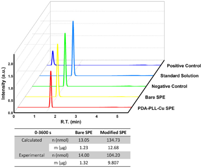
High-performance liquid chromatography (HPLC) results showing phenol concentration changes after 1 hour of electrooxidation. The table shows both the phenol reduction calculated from the chronoamperometry (CA) current and the exact phenol reduction measured via HPLC. On the PDA-PLL-Cu modified electrode, the concentration of phenol was reduced by 32%, while on the bare electrode the phenol concentration only reduced by 2% after oxidation removal. Abbreviations: PDA, polydopamine; PLL, poly-L-lysine; SPE, screen printed electrode.
As shown in Figure 6, insulin was preserved throughout the oxidization process. We changed the solution to human insulin injection (Myxredlin, Humulin R U-100, Novolin R) that pumped to flow cell. After an hour of electrooxidation, the first 10 µL was collected and measured on an HPLC system. The insulin peak intensity and integrated peak area did not change following electrooxidation. No other peaks appeared on the HPLC results indicating the insulin remained integral.
Figure 6.
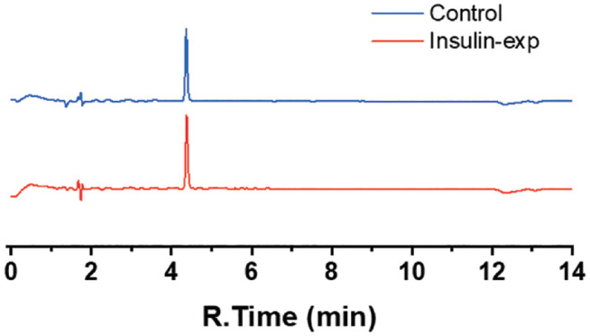
High-performance liquid chromatography (HPLC) results for insulin samples. Control is the insulin directly injected from human insulin injection without electrooxidation treatment. Insulin-exp is the insulin collected from flow cell after electrooxidation treatment. The intensity and integral area of insulin peak didn’t change between insulin collected from flow cell after electrooxidation and untreated insulin injection, indicating the insulin remained integrate in the solution after electrooxidation of phenols.
Conclusion
Electro-oxidization of phenolic compounds on polyelectrolyte modified surfaces can remove toxic preservatives while maintaining the integrity of insulin. As a proof of the concept, we used carbon screen printed electrodes, and achieved 32% removal of phenol from the solution in 1 hour. We consider this a very promising result, although increased removal may be required to achieve the desired reduction in tissue irritation. The performance of the screen printed electrode is inherently limited by its flat surface and low surface area/volume ratio (1.26 mm-1 for the SPEs used in our study). We believe that improved performance can be achieved by optimizing the design of the electrode, for example, by using a water permeable carbon electrode with higher surface area, like a porous carbon felt electrode with a surface area/volume ratio that can reach 22.1 to 22.7 mm-1. 52 For diabetes patients wearing infusion sets, an increase in wear times will mean better clinical outcomes, greater patient quality of life, reduced expenditures on supplies, and relief of pain from frequent canular exchange and injection. Increasing the lifetime of an infusion set has the potential to save billions of dollars in treating patients with diabetes.
Supplemental Material
Supplemental material, sj-docx-1-dst-10.1177_19322968221123083 for Electrooxidation of Phenol on Polyelectrolyte Modified Carbon Electrodes for Use in Insulin Pump Infusion Sets by Lingyun Zhou, David E. Huber, Bill van Antwerp and Sumita Pennathur in Journal of Diabetes Science and Technology
Acknowledgments
The authors would like to thank Dr Yude Su from University of Science and Technology of China, Suzhou Institute for Advanced Research, Qi Xie from Department of Chemistry Johns Hopkins University, Zhifang Du and Dr Jakkarin Limwongyut from Department of Chemistry and Biochemistry, University of California, Santa Barbara for the help on experimental setups and data analysis.
Footnotes
Abbreviations: CSII, continuous subcutaneous insulin infusion; SPE, screen printed electrode; PLL, poly-L-lysine; SEM, scanning electron microscopy; EIS, electrochemical impedance spectroscopy; HPLC, high-performance liquid chromatography; MDIs, multiple daily injections; PDA, polydopamine; CV, cyclic voltammetry; CA, chronoamperometry; PBS, phosphate buffer saline.
Authorship Confirmation/Contribution Statement: Lingyun Zhou: Conceptualization (equal); writing—original draft (lead); formal analysis (lead); writing—review and editing (equal). David Huber: Supervision (support); writing—original draft (supporting); Writing—review and editing (equal). Bill van Antwerp: Conceptualization (equal); Sumita Pennathur: Funding acquisition; supervision (lead); Writing—original draft (supporting); Writing—review and editing (equal).
The author(s) declared no potential conflicts of interest with respect to the research, authorship, and/or publication of this article.
Funding: The author(s) disclosed receipt of the following financial support for the research, authorship, and/or publication of this article: This work was supported in part by the Leona M. and Harry B. Helmsley Charitable Trust (Grant Number: 2019PGT1D022) and the American Diabetes Association Research Foundation (Grant Number: 1-17-VSN-18)
ORCID iDs: Lingyun Zhou  https://orcid.org/0000-0002-8506-856X
David E. Huber
https://orcid.org/0000-0001-5707-2097
Supplemental Material: Supplemental material for this article is available online.
References
- 1. Bruttomesso D, Costa S, Baritussio A. Continuous subcutaneous insulin infusion (CSII) 30 years later: still the best option for insulin therapy. Diabetes Metab Res Rev. 2009;25(2):99-111. doi: 10.1002/dmrr.931. [DOI] [PubMed] [Google Scholar]
- 2. Priesterroth L, Grammes J, Clauter M, Kubiak T. Diabetes technologies in people with type 1 diabetes mellitus and disordered eating: a systematic review on continuous subcutaneous insulin infusion, continuous glucose monitoring and automated insulin delivery. Diabet Med. 2021;38(7):e14581. doi: 10.1111/dme.14581. [DOI] [PubMed] [Google Scholar]
- 3. The DCCT Research Group. The Diabetes Control and Complications Trial (DCCT): design and methodologic considerations for the feasibility phase. Diabetes. 1986;35(5):530-545. doi: 10.2337/diab.35.5.530. [DOI] [PubMed] [Google Scholar]
- 4. Berget C, Messer LH, Forlenza GP. A clinical overview of insulin pump therapy for the management of diabetes: past, present, and future of intensive therapy. Diabetes Spectr. 2019;32(3):194-204. doi: 10.2337/ds18-0091. [DOI] [PMC free article] [PubMed] [Google Scholar]
- 5. Brazg R, Garg SK, Bhargava A, et al. Evaluation of extended infusion set performance in adults with type 1 diabetes: infusion set survival rate and glycemic outcomes from a pivotal trial. Diabetes Technol Ther. 2022;24(8):535-543. doi: 10.1089/dia.2021.0540. [DOI] [PMC free article] [PubMed] [Google Scholar]
- 6. Zhang G, Cohen O, Chattaraj S. Development of the extended infusion set and its mechanism of action. J Diabetes Sci Technol. 2022:19322968221112120. doi: 10.1177/19322968221112120. [DOI] [PMC free article] [PubMed] [Google Scholar]
- 7. Van Antwerp W. Insulin for implantable pumps. Annu Int Conf IEEE Eng Med Biol Soc. 2009:2009:238-241. doi: 10.1109/IEMBS.2009.5332860. [DOI] [PubMed] [Google Scholar]
- 8. Diaz D, Dinesen AR, Khalf A, et al. Functionality evaluation of investigational continuous subcutaneous insulin infusion (CSII) set vs. commercially available sets—assessment of 3D volume and surface area over eight days. Diabetes. 2018;67:980-P. doi: 10.2337/db18-980-P. [DOI] [Google Scholar]
- 9. Ponder SW, Skyler JS, Kruger DF, Matheson D, Brown BW. Unexplained hyperglycemia in continuous subcutaneous insulin infusion. Diabetes Educ. 2008;34(2):327-333. doi: 10.1177/0145721708315682. [DOI] [PubMed] [Google Scholar]
- 10. Kastner JR, Venkatesh N, Brown K, et al. Feasibility study of a prototype extended-wear insulin infusion set in adults with type 1 diabetes. Diabetes Obes Metab. 2022;24(6):1143-1149. doi: 10.1111/dom.14685. [DOI] [PubMed] [Google Scholar]
- 11. Hauzenberger JR, Münzker J, Kotzbeck P, et al. Systematic in vivo evaluation of the time-dependent inflammatory response to steel and Teflon insulin infusion catheters. Sci Rep. 2018;8:1132. doi: 10.1038/s41598-017-18790-0. [DOI] [PMC free article] [PubMed] [Google Scholar]
- 12. Swinney MR, Cox AL, Hawkins ED, et al. Insulin, not the preservative m-cresol, instigates loss of infusion site patency over extended durations of CSII in diabetic swine. J Pharm Sci. 2021;110:1418-1426. doi: 10.1016/j.xphs.2020.12.008. [DOI] [PubMed] [Google Scholar]
- 13. Kerr D, Morton J, Whately-Smith C, Everett J, Begley JP. Laboratory-based nonclinical comparison of occlusion rates using three rapid-acting insulin analogs in continuous subcutaneous insulin infusion catheters using low flow rates. J Diabetes Sci Technol. 2008;2(3):450-455. doi: 10.1177/193229680800200314. [DOI] [PMC free article] [PubMed] [Google Scholar]
- 14. Kastner JR, Eisler G, Torjman MC, et al. In vivo study of the inflammatory tissue response surrounding a novel extended-wear kink-resistant insulin infusion set prototype compared with a commercial control over two weeks of wear time. J Diabetes Sci Technol. 2022:19322968221093362. doi: 10.1177/19322968221093362. [DOI] [PMC free article] [PubMed] [Google Scholar]
- 15. Kesserwan S, Mulka A, Sharafieh R, et al. Advancing continuous subcutaneous insulin infusion in vivo: new insights into tissue challenges. J Biomed Mater Res. 2021;109:1065-1079. doi: 10.1002/jbm.a.37097. [DOI] [PMC free article] [PubMed] [Google Scholar]
- 16. Weber C, Kammerer D, Streit B, Licht AH. Phenolic excipients of insulin formulations induce cell death, pro-inflammatory signaling and MCP-1 release. Toxicol Rep. 2015;2:194-202. doi: 10.1016/j.toxrep.2014.11.019. [DOI] [PMC free article] [PubMed] [Google Scholar]
- 17. Michałowicz J, Duda W. Phenols—sources and toxicity. Pol J Environ Stud. 2007;16:347-362. [Google Scholar]
- 18. Sykes G, Hooper MC. Phenol as the preservative in insulin injections. J Pharm Pharmacol. 2011;6:552-557. doi: 10.1111/j.2042-7158.1954.tb10986.x. [DOI] [PubMed] [Google Scholar]
- 19. Teska BM, Alarcón J, Pettis RJ, Randolph TW, Carpenter JF. Effects of phenol and meta-cresol depletion on insulin analog stability at physiological temperature. J Pharm Sci. 2014;103(8):2255-2267. doi: 10.1002/jps.24039. [DOI] [PubMed] [Google Scholar]
- 20. Mulka A, Lewis BE, Mao L, et al. Phenolic preservative removal from commercial insulin formulations reduces tissue inflammation while maintaining euglycemia. ACS Pharmacol Transl Sci. 2021;4:1161-1174. doi: 10.1021/acsptsci.1c00047. [DOI] [PMC free article] [PubMed] [Google Scholar]
- 21. Eriksson H. Removal of toxic preservatives in pharmaceutical preparations of insulin by the use of ultra-stable zeolite Y. Biotechnol Tech. 1998;12:329-334. doi: 10.1023/A:1008866717990. [DOI] [Google Scholar]
- 22. Wang J, Jiang M, Lu F. Electrochemical quartz crystal microbalance investigation of surface fouling due to phenol oxidation. J Electroanal Chem. 1998;444:127-132. doi: 10.1016/S0022-0728(97)00583-4. [DOI] [Google Scholar]
- 23. Yang X, Kirsch J, Fergus J, Simonian A. Modeling analysis of electrode fouling during electrolysis of phenolic compounds. Electrochim Acta. 2013;94:259-268. doi: 10.1016/j.electacta.2013.01.019. [DOI] [Google Scholar]
- 24. Liu X, You S, Ma F, Zhou H. Characterization of electrode fouling during electrochemical oxidation of phenolic pollutant. Front Environ Sci Eng. 2021;15:53. doi: 10.1007/s11783-020-1345-7. [DOI] [Google Scholar]
- 25. Safavi A, Maleki N, Tajabadi F. Highly stable electrochemical oxidation of phenolic compounds at carbon ionic liquid electrode. Analyst. 2007;132(1):54-58. doi: 10.1039/b612672c. [DOI] [PubMed] [Google Scholar]
- 26. Andreescu S, Andreescu D, Sadik OA. A new electrocatalytic mechanism for the oxidation of phenols at platinum electrodes. Electrochem Commun. 2003;5:681-688. doi: 10.1016/S1388-2481(03)00166-8. [DOI] [Google Scholar]
- 27. Wang YQ, Gu B, Xu WL. Electro-catalytic degradation of phenol on several metal-oxide anodes. J Hazard Mater. 2009;162:1159-1164. doi: 10.1016/j.jhazmat.2008.05.164. [DOI] [PubMed] [Google Scholar]
- 28. Feng YJ, Li XY. Electro-catalytic oxidation of phenol on several metal-oxide electrodes in aqueous solution. Water Res. 2003;37(10):2399-2407. doi: 10.1016/S0043-1354(03)00026-5. [DOI] [PubMed] [Google Scholar]
- 29. Skládal P, Morozova NO, Reshetilov AN. Amperometric biosensors for detection of phenol using chemically modified electrodes containing immobilized bacteria. Biosens Bioelectron. 2002;17(10):867-873. doi: 10.1016/S0956-5663(02)00076-3. [DOI] [PubMed] [Google Scholar]
- 30. Lou C, Jing T, Zhou J, et al. Laccase immobilized polyaniline/magnetic graphene composite electrode for detecting hydroquinone. Int J Biol Macromol. 2020;149:1130-1138. doi: 10.1016/j.ijbiomac.2020.01.248. [DOI] [PubMed] [Google Scholar]
- 31. Noh S, Yang H. Sensitive phenol detection using tyrosinase-based phenol oxidation combined with redox cycling of catechol. Electroanalysis. 2014;26:2727-2731. doi: 10.1002/elan.201400383. [DOI] [Google Scholar]
- 32. Hua Z, Qin Q, Bai X, Huang X, Zhang Q. An electrochemical biosensing platform based on 1-formylpyrene functionalized reduced graphene oxide for sensitive determination of phenol. RSC Adv. 2016;6:25427-25434. doi: 10.1039/c5ra27563f. [DOI] [Google Scholar]
- 33. Rogers KR, Becker JY, Cembrano J. Improved selective electrocatalytic oxidation of phenols by tyrosinase-based carbon paste electrode biosensor. Electrochim Acta. 2000;45:4373-4379. doi: 10.1016/S0013-4686(00)00544-2. [DOI] [Google Scholar]
- 34. Önnerfjord P, Emnéus J, Marko-Varga G, Gorton L, Ortega F, Domínguez E. Tyrosinase graphite-epoxy based composite electrodes for detection of phenols. Biosens Bioelectron. 1995;10:607-619. doi: 10.1016/0956-5663(95)96937-T. [DOI] [Google Scholar]
- 35. Pirvu C, Manole CC. Electrochemical surface plasmon resonance for in situ investigation of antifouling effect of ultra thin hybrid polypyrrole/PSS films. Electrochim Acta. 2013;89:63-71. doi: 10.1016/j.electacta.2012.11.045. [DOI] [Google Scholar]
- 36. Wang J, Deo RP, Musameh M. Stable and sensitive electrochemical detection of phenolic compounds at carbon nanotube modified glassy carbon electrodes. Electroanalysis. 2003;15:1830-1834. doi: 10.1002/elan.200302772. [DOI] [Google Scholar]
- 37. Humalog [package insert]. Eli Lilly and Company; 2011. [Google Scholar]
- 38. Novolog [package insert]. Novo Nordisk Inc.; 2009. [Google Scholar]
- 39. Fujieda N, Umakoshi K, Ochi Y, et al. Copper–oxygen dynamics in the tyrosinase mechanism. Angew Chem. 2020;132:13487-13492. doi: 10.1002/ange.202004733. [DOI] [PubMed] [Google Scholar]
- 40. Hoffmann A, Citek C, Binder S, et al. Catalytic phenol hydroxylation with dioxygen: extension of the tyrosinase mechanism beyond the protein matrix. Angew Chem Int Ed. 2013;52:5398-5401. doi: 10.1002/anie.201301249. [DOI] [PMC free article] [PubMed] [Google Scholar]
- 41. Fenoll LG, Peñalver MJ, Rodríguez-López JN, Varón R, García-Cánovas F, Tudela J. Tyrosinase kinetics: discrimination between two models to explain the oxidation mechanism of monophenol and diphenol substrates. Int J Biochem Cell Biol. 2004;36(2):235-246. doi: 10.1016/S1357-2725(03)00234-6. [DOI] [PubMed] [Google Scholar]
- 42. Mirica LM, Vance M, Rudd DJ, et al. Tyrosinase reactivity in a model complex: an alternative hydroxylation mechanism. Science. 2005;308:1890-1892. doi: 10.1126/science.1112081. [DOI] [PubMed] [Google Scholar]
- 43. Lee H, Dellatore SM, Miller WM, Messersmith PB. Mussel-inspired surface chemistry for multifunctional coatings. Science. 2007;318:426-430. doi: 10.1126/science.1147241. [DOI] [PMC free article] [PubMed] [Google Scholar]
- 44. Kim M, Song KH, Doh J. PDMS bonding to a bio-friendly photoresist via self-polymerized poly(dopamine) adhesive for complex protein micropatterning inside microfluidic channels. Colloids Surf B Biointerfaces. 2013;112:134-138. doi: 10.1016/j.colsurfb.2013.07.021. [DOI] [PubMed] [Google Scholar]
- 45. Lee HA, Ma Y, Zhou F, Hong S, Lee H. Material-independent surface chemistry beyond polydopamine coating. Acc Chem Res. 2019;52:704-713. doi: 10.1021/acs.accounts.8b00583. [DOI] [PubMed] [Google Scholar]
- 46. Ou J, Wang J, Liu S, Zhou J, Yang S. Self-assembly and tribological property of a novel 3-layer organic film on silicon wafer with polydopamine coating as the interlayer. J Phys Chem C. 2009;113:20429-20434. doi: 10.1021/jp9073416. [DOI] [Google Scholar]
- 47. Hatano M, Nozawa T, Ikeda S, Yamamoto T. The catalytic activity of the poly-L-lysine-copper(II) complex on the oxidation of 3.4-dihydroxyphenylalanine. Makromol Chem. 1971;141:11-19. doi: 10.1002/macp.1971.021410102. [DOI] [Google Scholar]
- 48. Zhang Y, Lynge ME, Teo BM, Ogaki R, Städler B. Mixed poly(dopamine)/poly(L-lysine) (composite) coatings: from assembly to interaction with endothelial cells. Biomater Sci. 2015;3(8):1188-1196. doi: 10.1039/c5bm00093a. [DOI] [PubMed] [Google Scholar]
- 49. Daly WH, Poché D. The preparation of N-carboxyanhydrides of α-amino acids using bis(trichloromethyl)carbonate. Tetrahedron Lett. 1988;29:5859-5862. doi: 10.1016/S0040-4039(00)82209-1. [DOI] [Google Scholar]
- 50. Vermette P, Meagher L. Interactions of phospholipid- and poly(ethylene glycol)-modified surfaces with biological systems: relation to physico-chemical properties and mechanisms. Colloids Surf B Biointerfaces. 2003;28:153-198. doi: 10.1016/S0927-7765(02)00160-1. [DOI] [Google Scholar]
- 51. Bellassai N, Marti A, Spoto G, Huskens J. Low-fouling, mixed-charge poly-l-lysine polymers with anionic oligopeptide side-chains. J Mater Chem B. 2018;6:7662-7673. doi: 10.1039/C8TB01619D. [DOI] [PubMed] [Google Scholar]
- 52. González-García J, Bonete P, Expósito E, Montiel V, Aldaz A, Torregrosa-Maciá R. Characterization of a carbon felt electrode: structural and physical properties. J Mater Chem. 1999;9:419-426. doi: 10.1039/a805823g. [DOI] [Google Scholar]
Associated Data
This section collects any data citations, data availability statements, or supplementary materials included in this article.
Supplementary Materials
Supplemental material, sj-docx-1-dst-10.1177_19322968221123083 for Electrooxidation of Phenol on Polyelectrolyte Modified Carbon Electrodes for Use in Insulin Pump Infusion Sets by Lingyun Zhou, David E. Huber, Bill van Antwerp and Sumita Pennathur in Journal of Diabetes Science and Technology