Abstract
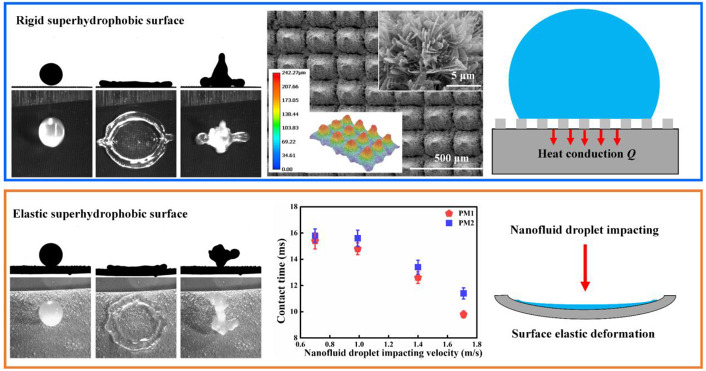
Ice accumulation on cold surfaces is a common and serious phenomenon that exists in numerous industrial fields, such as power transmission, wind turbines, and aircraft. Despite recent efforts in mitigating ice accumulation on the cold surface, it remains a challenge to achieve robust anti-icing on the cold surface in terms of nanofluid droplet. Here, we report a rigid superhydrophobic Cu surface and an elastic polydimethylsiloxane (PDMS) superhydrophobic surface to enhance water-repellency performance, characterized by a significant reduction in contact time and a decrease in the spreading ratio. As for the rigid superhydrophobic Cu surface, the underlying mechanism is ascribed to the existence of stable air cushions between the micropillar array, which reduce the contact area and further suppress the heat conduction. As for the elastic PDMS superhydrophobic surface, the rapid detachment of the nanofluid droplet relies on superior surface elasticity, which can further suppress the nanofluid droplet splashing at a high impacting velocity. We believe that this work can provide a new view for the improvement of water-repellency for a wide range of applications.
1. Introduction
Ice accumulation on cold surfaces presents a serious hazard in numerous industrial fields such as power transmission, wind turbines, and aircraft.1−3 The occurrence of ice accretion on the windward surface of the aircraft not only affects the aerodynamic performance but also damages the safety of the aircraft.4,5 Therefore, it is of great practical importance to develop an effective and reliable method to reduce ice accumulation. As such, numerous strategies have been proposed to mitigate ice accumulation on the cold surface. One research strategy is to remove ice through external stimuli such as electric,6,7 thermal,8−10 chemical,11 and pneumatics.12,13 However, this method of alleviating ice accumulation is energy-consuming and inefficient. The other research strategy is to suppress ice formation by reducing ice adhesion,14−16 which is considered as the most effective way because it does not require any external energy. To this end, much attention has been paid to develop surfaces with anti-icing properties to reduce ice adhesion.
Foremost among these studies to reduce ice adhesion is the utilization of a superhydrophobic surface because of the ice-repellent property and the high nucleation barrier in a limited range.17−21 It should be noted that the superhydrophobic surface is not always effective for anti-icing due to the increased substrate-ice interfacial area and enhanced ice adhesion strength once the ice is formed on the surface.22 It is reported that the superhydrophobic surface with hierarchical micro/nanostructures can reduce ice adhesion and delay ice formation by reducing contact area and suppressing heat conduction from the nanofluid droplet to the cold surface.23−25 For example, a superhydrophobic surface with a hierarchical structure shows robust water and ice repellency at low temperatures (−20 °C) for three months.26 The icephobicity and superhydrophobicity of the hierarchically structured surfaces were superior to those of the single-structured surface.27 The low adhesion was measured on the superhydrophobic surface due to the presence of stable air cushion compared to the smooth surface.28 It is possible that hierarchically structured surfaces direct the rolling of the droplet because of their high vapor-to-solid ratios.29,30 In addition to surface structure, surface stiffness is found to be another key factor that can enhance superhydrophobicity and reduce ice adhesion under dynamic conditions.31−33 There is a broad palette of surfaces in nature and technology that is characterized by some degree of elasticity, i.e., leaves, construction materials, textiles,34etc. Extensive work has been done to prove that contact time reduction and heat conduction suppression can be achieved on a cold elastic surface.35,36
Nanofluid, an emerging material of heat transfer medium, is a kind of suspension of nanoparticles such as Al2O3, TiO2, and CuO in a base fluid.37,38 Owing to the excellent heat transfer rate and the enhanced thermal conductivity, nanofluid has made substantial research progress in thermal applications like air conditioning, solar panels, and heat exchangers.39,40 For instance, a water-based Al2O3 nanofluid was suggested for improving the thermal performance of solar thermal collectors at low temperatures.41 Unfortunately, most of them which utilize the nanofluid as the work fluid will lose the enhanced thermal performance when in a subzero degree condition. The reason for losing thermal performance is that the nanofluid would freeze at a subzero temperature. Accordingly, it is still a great challenge for rigid or elastic superhydrophobic surfaces to achieve anti-icing/deicing performance in terms of the nanofluid droplet, which is essential to understand the feasibility of implementing nanofluids for phase change enhancement.
Herein, we developed a rigid superhydrophobic Cu surface and an elastic polydimethylsiloxane (PDMS) superhydrophobic surface to reduce the contact time and achieve water-repellency. The hierarchical micro/nanostructure of the micropillar array on the rigid superhydrophobic Cu surface induces stable air cushions underneath the nanofluid droplet. The air cushions between the nanofluid droplet and the cold superhydrophobic Cu surface reduce the contact area and further suppress the heat conduction. In addition, owing to the superior surface elasticity, the elastic PDMS superhydrophobic surface motivates the rapid detachment of the nanofluid droplet. Compared to the rigid superhydrophobic Cu surface, the introduction of surface elasticity effectively reduces the contact time and suppresses nanofluid droplet splashing. The underlying mechanism is explored based on the heat transfer and the energy conversion during the impacting process. Moreover, the influence of the nanofluid droplet impact velocity on the cold rigid and elastic superhydrophobic surfaces is quantitatively analyzed. Note that all of the impacting nanofluid droplets on the cold rigid superhydrophobic Cu surface or on the cold elastic PDMS superhydrophobic surface can rebound off the surface without ice crystal formation, which validates the water-repellency of the as-fabricated surface in this work.
2. Experimental Section
2.1. Materials
Al2O3 nanoparticles (diameter of 10–15 nm) were purchased from Shanghai Chaowei Nano Technology Co. Ltd., China. Na3PO4·12H2O was supplied by Shanghai Macklin Biochemical Co. Ltd., China. NaClO2 was obtained from Shanghai Aladdin Biochemical Technology Co. Ltd., China. 1H,1H,2H,2H-Perfluorooctyl-trichlorosilane was provided from Alfa Aisha Chemical Co. Ltd., China. Polydimethylsiloxane (PDMS) prepolymer (Sylgard 184) and curing agent were purchased from Dow Corning. All of the chemicals were used as received. Poly(methyl methacrylate) (PMMA) was provided from a local store. The copper foils were purchased from a local market.
2.2. Fabrication of Al2O3 Nanofluid
The Al2O3 nanoparticles (diameter of 10–15 nm) of 0.05, 0.10, and 0.15 g were weighed using an electronic balance. The nanofluid with three different concentrations of 0.5, 1, and 1.5 wt % was successfully synthesized by dispersing the Al2O3 nanoparticles with different weights in 10 mL of pure water, respectively. In order to avoid settling, the mixtures were ultrasonically vibrated for 30 min before use.
2.3. Fabrication of Rigid Superhydrophobic Cu Surface
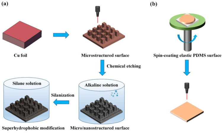
We fabricated the rigid superhydrophobic Cu surface via a combined laser-ablation and wet chemical etching method (Figure 1a). Copper foils (20 × 20 × 1 mm) were first polished by using sandpaper sheets of grit size 180, 320, 600, 1000, 1500, and 2000, sequentially. The polished copper foils were cleaned with ethanol, isopropyl alcohol, and deionized (DI) water under ultrasonic treatment for 30 min. Then, an array of square patterns with spacing of 100 μm, 125 μm, and 150 μm was selectively inscribed on the copper substrates using a commercial fiber laser-engraving system (PLS6MW, Universal Laser Systems, Inc., Scottsdale, AZ; 40 W, laser wavelength = 1.06 μm, laser beam diameter = 0.001 in) at a laser power of 28 W, speed of 0.1788 m/s, and frequency of 30 kHz. Excess copper particles were observed on the samples with 2 M HCl aqueous solution and DI water. After that, to obtain nanostructures of samples, the copper surfaces with micropillars array were immersed in a hot alkaline solution (95 ± 5 °C) for 30 min which was composed of NaClO2, NaOH, Na3PO4·12H2O, and DI water (3.75:5:10:100 wt %), followed by being washed with DI water. Furthermore, to render the surfaces superhydrophobicity, the samples were immersed in a 1 mM n-hexane solution of 1H,1H,2H,2H-perfluorooctyl-trichlorosilane for 30 min and then heated at ∼150 °C for 1 h. In this work, three sets of rigid hierarchical micro/nanostructured superhydrophobic Cu surfaces with pillar edge-to-edge spacing of 100 μm (MN100), 125 μm (MN125), and 150 μm (MN150) were successfully fabricated (Figure S1 and Table S1, Supporting Information). For comparison, the nanostructured (N) superhydrophobic Cu surface without the existence of the micropillars array was also prepared by using the chemical etching technology as mentioned above.
Figure 1.
(a) Schematic drawing of the fabrication process of the rigid superhydrophobic Cu surface. (b) Schematic drawing of the fabrication process of the elastic PDMS superhydrophobic surface.
2.4. Fabrication of Elastic PDMS Superhydrophobic Surface
We constructed the elastic PDMS surface based on
spin-coating technology (Figure 1b). The PDMS prepolymer and curing agent were first
mixed in a weight ratio of 30:1 and degassed in a vacuum chamber for
1 h. The PDMS solution was then rotated on a poly(methyl methacrylate)
(PMMA) substrate by spin-coating to get a thin layer. After the thin
layer of PDMS solution was cured at 80 °C for 4 h, the PDMS elastic
surface was successfully fabricated by being carefully peeled off
the PMMA substrate. The length l and the width w of the PDMS elastic surface are 16 mm and 8 mm, respectively.
The thickness h of the PDMS elastic surface can be
adjusted by the duration and speed of the spin coating process. Finally,
in order to induce low surface energy of the PDMS elastic surface,
the laser raster-scanning process was employed to gently ablate the
superficial layer of the PDMS elastic surface at a laser power of
20 W, speed of 2.54 m/s, and frequency of 30 kHz. In this work, two
sets of PDMS elastic surfaces with stiffness k (
 ) of ∼0.65 N/m (h ∼ 0.5 mm, denoted as PM1) and k of ∼5.21
N/m (h ∼ 1 mm, denoted as PM2) were fabricated,
where E is the elastic modulus (E ≈ 0.67 MPa) and I (
 ) is the area moment of inertia.
2.5. Characterization
The morphologies of hierarchical micro/nanostructured superhydrophobic Cu surfaces and elastic PDMS superhydrophobic surfaces were observed by scanning electron microscopy (SEM, FEI Quant 250FEG). The larger 3D structures of the samples were observed by using a digital microscope (Keyence/VHX-6000, VH-Z100R wide-range zoom lens). The static contact angles and contact angle hysteresis were measured with a Ramé-Hart goniometer (model 290-U1). Droplets of ∼10 μL volume were gently deposited on the samples. The static contact angles were measured using goniometer optics. The value of contact angle hysteresis was calculated by measuring the advancing and receding angles via adding and removing liquid from a droplet deposited on the surface. The difference between the advancing angle and the receding angle was defined as the value of the contact angle hysteresis. To ensure the repeatability of the results, all experiments were repeated three times at different locations on each sample.
2.6. Visualization Experimental Setup of Nanofluid Droplet Impacting Process
During the experiment, the ambient temperature is 25 ± 1 °C and the relative humidity is 55 ± 5%. The visualization experiment of nanofluid droplet impact was carried out on a sealed PMMA chamber. To avoid condensation and frost formation, dry nitrogen was constantly filled into the sealed PMMA chamber. The relative humidity of the sealed chamber was recorded with a humidity sensor (Testo 605i, Thermo-Hygrometer Smart Probe, German). The relative humidity inside the sealed PMMA chamber was kept at 5 ± 0.5%. The ambient temperature inside the sealed PMMA chamber was recorded by using a thermometer (LE506, deLi), and it was maintained at 25 ± 1 °C. Initially, the cold samples were horizontally placed on the sealed PMMA chamber. For comparison purposes, the nanofluid droplet impacting dynamic was also conducted on the cold rigid PDMS superhydrophobic surface (surface temperature ∼ −5 °C). The rigid PDMS surface was simulated by placing a glass slide under a cold elastic PDMS superhydrophobic surface. The temperature of the hierarchical micro/nanostructured superhydrophobic Cu surface, the temperature of the elastic PDMS superhydrophobic surface, and the temperature of the rigid PDMS superhydrophobic surface were acquired by a thermocouple temperature meter (AS887, Smart Sensor) and were all fixed at −5 °C in the experiment. A nanofluid droplet (nanoparticle concentration ∼1 wt %) with a diameter of ∼2.6 mm formed at the tip of a steel needle from a syringe pump (LSPO1–1A, LongerPump) impacted the center of the sample due to the gravitational force. The temperature of the nanofluid droplet (25 ± 1 °C) is constant with ambient temperature in the sealed PMMA chamber. To vary the impact velocity, the impact height of the nanofluid droplet was changed by adjusting the distance between the needle and the sample. The dynamic process of the droplet impingement was captured at 5000 fps by two high-speed cameras mounted horizontally (v1212, Phantom) and vertically (Y4–S1, IDT).
The experimental platform of the nanofluid droplet impacting elastic PDMS superhydrophobic surfaces was the same as the platform of the nanofluid droplet impacting hierarchical micro/nanostructured superhydrophobic Cu surfaces apart from the cooling system. As for the nanofluid droplet impacting on the hierarchical micro/nanostructured superhydrophobic Cu surfaces, the hierarchical micro/nanostructured superhydrophobic Cu surfaces were directly placed at a cooling stage (Cole-Parmer Standard Benchtop Chilling Block) and the sample temperature was kept at −5 °C. As for the nanofluid droplet impacting on elastic PDMS superhydrophobic surfaces, the elastic PDMS superhydrophobic surfaces which were supported by fixing both ends on the mountings were hung on the cold side of the semiconductor cooler (XH-C1206, SINHEA ELECTRON). The temperature of the elastic PDMS superhydrophobic surfaces was maintained at −5 °C. The temperature (−30 °C) of the cold side of the semiconductor cooler was controlled by the DC regulated power supply. The temperature (−10 °C) of the heat side of the semiconductor cooler was cooled by the cooling stage (Cole-Parmer Standard Benchtop Chilling Block).
2.7. Statistical Analysis
The droplet dynamics were analyzed with Phantom v1212 (Vision Research, USA) and ImageJ (National Institutes of Health, USA) software. Statistical analysis was done by using Origin 8.0 (Origin-Lab Corporation, USA) software, and all results were reported as means ± standard deviation. In all the statistical analyses, the differences between multiple groups were analyzed using the one-way analysis of variance (ANOVA), and the values of p < 0.05 were considered as statistically significant.
3. Results and Discussion
3.1. Fabrication and Characterization of the Rigid and Elastic Superhydrophobic Surface
We fabricated a rigid superhydrophobic Cu surface via a combined laser-ablation and wet chemical etching method (Figure 1a), and we constructed an elastic PDMS surface based on spin-coating technology (Figure 1b). In this work, three sets of rigid hierarchical micro/nanostructured superhydrophobic Cu surfaces with pillar edge-to-edge spacing of 100 μm (MN100), 125 μm (MN125), and 150 μm (MN150) were successfully fabricated, respectively (Figure S1 and Table S1, Supporting Information). For comparison, the nanostructured (N) superhydrophobic Cu surface without the existence of the micropillar array was also prepared. Meanwhile, two sets of PDMS elastic surfaces with stiffness k of ∼0.65 N/m (h ∼ 0.5 mm, denoted as PM1) and k of ∼5.21 N/m (h ∼ 1 mm, denoted as PM2) were fabricated (see Experimental Section in detail).
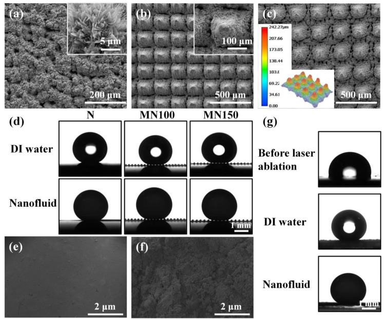
Figure 2a–c shows the scanning electron microscopy (SEM) images of N, MN100, and MN150 Cu surfaces, respectively. After chemical etching treatment, the N, MN100, and MN150 Cu surfaces were all covered with a layer of CuO sheets, giving the surface a rough nanostructure (Figure 2a). The SEM images of the MN100 surface and MN150 surface exhibit a uniform tapered micropillar array with edge-to-edge spacing of 100 and 150 μm, respectively (Figure 2b). As can be seen from the top-view image in Figure 2c, the micropillar array of MN150 has a height larger than 200 μm. After a silanization treatment, the N, MN100, and MN150 Cu surfaces are superhydrophobic. The static contact angle and contact angle hysteresis of a DI water droplet or a nanofluid droplet (nanoparticle concentration ∼1 wt %) on the N, MN100, and MN150 surfaces is ∼160° and ∼2°, respectively (Figure 2d). Moreover, air trapping can be seen at the solid–vapor interfaces of MN100 and MN150 surfaces. The high static contact angle and the low contact angle hysteresis of the samples, as well as the existence of an air-trapping phenomenon, confirm the Cassie–Baxter wetting state of MN100 and MN150 surfaces. Besides, SEM images of the elastic PDMS surfaces before and after laser ablation can be seen in Figure 2e,f. The pristine elastic PDMS surface is almost smooth without rough structures before laser ablation, while after laser ablation, the elastic PDMS surface is covered with microparticles. The existence of microparticles endows the surface with superhydrophobicity. The static contact angle of a DI water/nanofluid droplet (nanoparticle concentration ∼1 wt %) on the elastic PDMS surface increases from 120° to 160° after laser ablation (Figure 2g).
Figure 2.
SEM images of (a) N superhydrophobic Cu surface, (b) MN100 superhydrophobic Cu surface, and (c) MN150 superhydrophobic Cu surface, respectively. (d) Local DI water contact angle and local nanofluid contact angle on the N, MN100, and MN150 superhydrophobic Cu surfaces, respectively. SEM images of PDMS elastic surface (e) before laser ablation and (f) after laser ablation. (g) The local DI water contact angle on the elastic PDMS surface before laser ablation, DI water contact angle after laser ablation, and nanofluid contact angle after ablation, respectively.
3.2. Dynamic Process of the Nanofluid Droplet Impacting on the Cold Rigid and Elastic Superhydrophobic Surfaces
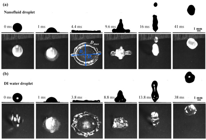
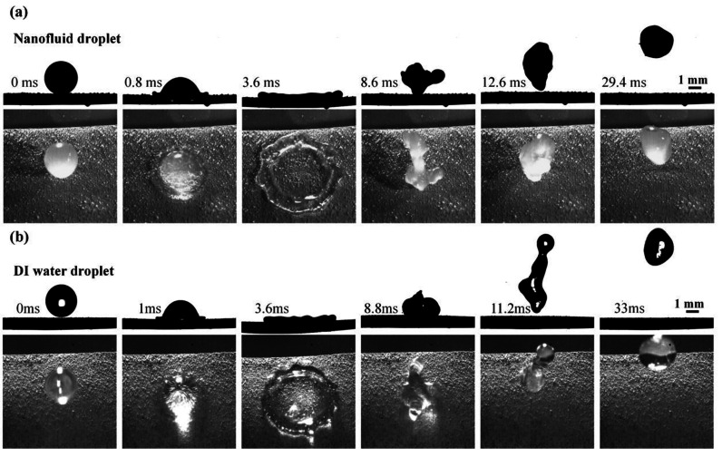
Figure 3 shows the impacting
dynamics of a nanofluid droplet on the cold MN100 Cu superhydrophobic
surface with an impacting velocity of 1.4 m/s (Figure S2, Supporting Information). The effect of the nanoparticle
concentration of nanofluid droplets on impact dynamics is shown in Figure S3 and Figure S4 (Section S1, Supporting Information).
Upon touching the surface, the nanofluid droplet spreads to its maximum
diameter Dmax at 4.4 ms in an approaching
circle shape (see the top-view image in Figure 3). Here, 
 , where Dl is
the maximum lateral diameter of the droplet and Dv is the maximum vertical diameter of the droplet. The
circle shape of the nanofluid droplet is surrounded by an edge bump,
which is attributed to a synergy of the surface tension and surface
wettability. Then the nanofluid droplet retracts at 9.6 ms and completely
bounces off of the cold MN100 superhydrophobic surface at 16 ms. After
the nanofluid droplet bounces off the cold surface, there is no residue
of tiny droplets left on the surface, demonstrating the superior superhydrophobicity
of the MN100 surface. The comparison of DI water droplet impacting
dynamics on the cold MN100 Cu superhydrophobic surface with an impacting
velocity of 1.4 m/s is illustrated in Figure 3b. It can be seen that the DI water droplet
exhibits similar impacting behavior. The DI water droplet reaches
its maximum spreading diameter Dmax at
3.8 ms, which is earlier than that of the nanofluid droplet. Besides,
the detaching time of the DI water droplet is ∼13.8 ms, which
is shorter than that of the impacting nanofluid droplet on the cold
MN100 superhydrophobic surface.
Figure 3.
Selected snapshots of (a) a nanofluid droplet and (b) a DI water droplet impacting the cold MN100 superhydrophobic Cu surface (−5 °C) at a velocity of 1.4 m/s.
Nanofluid droplet impact dynamics is also strongly affected by the surface stiffness k. Figure 4 exhibits the selective snapshots of a nanofluid droplet at the velocity of 1.4 m/s impacting the cold elastic PM1 superhydrophobic surface. Differing from the dynamic impacting process of the nanofluid droplet on the cold MN100 superhydrophobic Cu surface, the impacting nanofluid droplet on the cold elastic PDMS surface is accompanied by surface elastic deformation. When the nanofluid droplet spreads on the cold elastic surface at 3.6 ms, a downward movement of the elastic surface is simultaneously induced by the elastic surface deformation. Accordingly, before the nanofluid droplet fully spreads on the cold elastic surface, an upward movement of the elastic surface is triggered. After that, the nanofluid droplet bounces off the surface at 12.6 ms before fully recoiling. Similarly, a DI water droplet at a velocity of 1.4 mm/s impacting the cold elastic PM1 superhydrophobic surface is shown in Figure 4b. The spreading diameter Dmax of the DI water droplet is smaller than that of the nanofluid droplet within the same time interval at 3.6 ms, leading to a shorter contact time of the DI water droplet (∼11.2 ms) under the same experimental conditions.
Figure 4.
Selected snapshots of (a) a nanofluid droplet and (b) a DI water droplet impacting the cold elastic PM1 superhydrophobic surface (−5 °C) at a velocity of 1.4 m/s.
3.3. Mechanism of the Nanofluid Droplet Impacting on the Cold Rigid Superhydrophobic Surface
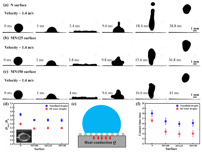
To elucidate the mechanism of the nanofluid droplet impacting the cold rigid superhydrophobic Cu surface, we investigate the influence of micropillar edge-to-edge spacing on the nanofluid droplet impacting dynamics. Figure 5a–c shows the selected snapshots of a nanofluid droplet impacting on the cold N (without micropillar array), MN125, and MN150 surfaces at a velocity of 1.4 m/s. During the impacting process, the nanofluid droplet on the cold N and the cold MN Cu surfaces displays different spreading behaviors, which are quantified by using the spreading ratio Dmax/D0 (see the inset image in Figure 5d). It can be seen that the spreading ratio Dmax/D0 of the impinging nanofluid droplet on the cold N surface (∼2.9) is much larger than the nanofluid droplet on the cold MN surfaces.
Figure 5.
(a) Selected snapshots of a nanofluid droplet impacting the cold N superhydrophobic Cu surface (−5 °C) at a velocity of 1.4 m/s. (b) Selected snapshots of a nanofluid droplet impacting the cold MN125 superhydrophobic Cu surface (−5 °C) at a velocity of 1.4 m/s. (c) Selected snapshots of a nanofluid droplet impacting the cold MN150 superhydrophobic Cu surface (−5 °C) at a velocity of 1.4 m/s. (d) Comparison of spreading ratio Dmax/D0 of the nanofluid droplet and the DI water droplet on the cold N, MN100, MN125, and MN150 superhydrophobic Cu surfaces (−5 °C) at a velocity of 1.4 m/s. (e) Schematic illustration of heat transfer from the nanofluid droplet to the cold Cu superhydrophobic surface. (f) Contact time of the nanofluid droplet and the DI water droplet on the cold N, MN100, MN125, and MN150 superhydrophobic Cu surfaces (−5 °C) at a velocity of 1.4 m/s.
The manifestation of the large spreading ratio Dmax/D0 of the nanofluid droplet on the cold N surface is due to the lack of micropillars, which would further prolong the contact time on the N surface. When a nanofluid droplet impacts the cold MN surfaces, the air cushions between the micropillar array reduce the contact area between the nanofluid droplet and the cold surfaces, resulting in a small spreading ratio Dmax/D0. Notably, the smallest spreading ratio Dmax/D0 of nanofluid droplets is ∼2.6, which appears on the cold MN150 surface. For comparison, the spreading ratio Dmax/D0 of DI water droplets on the cold N, MN125, and MN150 surfaces with a velocity of 1.4 m/s is also displayed in Figure 5d. It can be seen that the spreading ratio Dmax/D0 of the DI water droplet on the MN150 surface (with a micropillar array) is significantly smaller than that of the DI water droplet on the N surface (without micropillars array). However, the spreading ratio Dmax/D0 of the DI water droplet is much smaller than that of the nanofluid droplet on the same surface, which is due to the difference in heat transfer between the DI water droplet and the nanofluid droplet on the cold surface.
For a better understanding of the heat transfer process of the nanofluid droplet on the cold superhydrophobic Cu surface, we establish a heat transfer model that links the heat conduction from the nanofluid droplet to the cold rigid superhydrophobic Cu surface. As is depicted in Figure 5e, by ignoring the influence of heat conduction from air to the nanofluid droplet and heat irradiation from the nanofluid droplet to the cold surface, the value of heat conduction can be expressed as
| 1 |
where k is the thermal conductivity between the droplet and the cold micro/nanostructured superhydrophobic Cu surface, A is the contact area of the droplet on the cold surface, ΔT is the temperature difference between the nanofluid droplet and the cold rigid Cu surface, and δ is the thickness of thermal conduction layer between the nanofluid droplet and the cold rigid superhydrophobic Cu surface.
Apparently, the value of Q is highly dependent on k and A. The small contact area A (characterized by Dmax/D0) between the nanofluid droplet and the cold surface would give rise to a decreased Q. In terms of the impacting nanofluid droplet on the cold N surface, it has the largest contact area A. Compared with the nanofluid droplet on the cold N surface, the impacting nanofluid droplet on the cold MN surface shows a smaller A. The decrease in the contact area A results from the air pockets trapped underneath the nanofluid droplets on the MN surfaces, which is induced by the micropillar array with large edge-to-edge spacing. It should be emphasized that, when in a limited range, the larger the micropillars array edge-to-edge spacing of the MN surfaces is, the smaller A and the smaller Q is. When the micropillar array spacing is larger than the limited range, the Laplace pressure inside the microcavities decreases. Therefore, the impacting nanofluid droplet might penetrate inside the microvities, resulting in an increase in A.42,43 In this work, the minimum value and the maximum value of heat conduction Q appear on the cold MN150 Cu surface and on the cold N Cu surface, respectively. In addition, in terms of a DI water droplet impacting the cold superhydrophobic Cu surface, the heat conduction Q between the DI water droplet and the cold surface is much smaller than that of the nanofluid droplet. This mainly relies on two factors: first, the heat conductivity of the DI water droplet (∼0.60 W/(m·K)) is smaller than that of the nanofluid droplet (∼0.65 W/(m·K));44−46 second, the DI water droplet owns a smaller contact area A on the cold surface (Figure 5d). Furthermore, the contact time of the nanofluid droplet is depicted in Figure 5f. As shown, the contact time of the nanofluid droplet on the cold MN surfaces is smaller than that of the nanofluid droplet on the cold N Cu surface. For example, the contact time of the nanofluid droplet on the cold N surface is ∼18.0 ms, whereas the contact time of the nanofluid droplet on the MN125 surface is ∼15.9 ms. Besides, owing to the smaller heat conduction Q between the DI water droplet and the cold suprahydrophobic Cu surface, the contact time of the DI water droplet is shorter than that of the nanofluid droplet under the same experimental conditions.
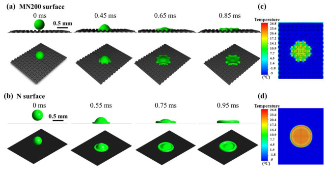
As heat conduction plays a vital role in affecting the outcome of the nanofluid droplet impacting dynamics, we further demonstrate how the heat transfer rate influences the impacting dynamics of the nanofluid droplet by using numerical simulations.47,48 We perform numerical simulation of the nanofluid droplet (diameter = 0.5 mm, nanofluid droplet temperature = 25 °C) impacting on the cold MN200 and cold N superhydrophobic surfaces (surface temperature = −5 °C) at an impacting velocity of 1.4 mm/s by using the Volume-of-Fluid (VOF) method. The temperature distribution of the cold surface upon the nanofluid droplet impact is calculated via the Pressure-Implicit Splitting of Operators (PISO) algorithm. Figure 6a,b shows the nanofluid spreading period from the moment that the nanofluid droplet touches the surface to the moment that the nanofluid droplet reaches the maximum spreading ratio. As shown, the simulated nanofluid droplet spreads to its maximum diameter in an approaching circle shape and is also surrounded by an edge bump, which is in accordance with the experimental observation. Meanwhile, the nanofluid droplet reaches its maximum spreading ratio on the MN200 surface at 8.5 ms, which is earlier than the nanofluid droplet on the N surface (∼9.5 ms). The maximum spreading ratio of the nanofluid droplet on the MN200 surface is ∼1.8, and the maximum spreading ratio of the nanofluid droplet on the N surface is ∼2.1.
Figure 6.
(a) Simulations of the dynamic process of a nanofluid droplet impacting the cold MN200 superhydrophobic Cu surface (−5 °C) at a velocity of 1.4 m/s. (b) Simulations of the dynamic process of a nanofluid droplet impacting the cold N superhydrophobic Cu surface (−5 °C) at a velocity of 1.4 m/s. (c) Simulations of the temperature distribution on the cold MN200 superhydrophobic Cu surface at the moment when the nanofluid droplet reaches its maximum spreading ratio. (d) Simulations of the temperature distribution on the cold N superhydrophobic Cu surface at the moment when the nanofluid droplet reaches its maximum spreading ratio.
The differences in impacting dynamics of the nanofluid droplet on the cold MN200 and N surfaces are further explained based on the heat transfer rate. Figure 6c,d exhibits the temperature distribution on the MN200 and N surfaces when the nanofluid droplet reaches its maximum spreading ratio. At the moment when the nanofluid droplet reaches its maximum spreading ratio, there is a temperature rise both on the MN 200 surface and N surface due to the heat transfer. A higher surface temperature is ascribed to a larger heat transfer rate of the nanofluid droplet to the cold surface. As for the nanofluid droplet impact on the same surface, the heat transfer rate of the impacting center and the heat transfer rate of the rim of the lamella are different. As is depicted in Figure 6c, the maximum surface temperature of the micropillar at the impacting center on the MN200 surface is ∼21.5 °C, and the maximum surface temperature of the micropillar at the rim of the lamella on the MN200 surface is ∼12.8 °C. This means the heat transfer rate at the impacting center is larger than that at the rim of the lamella. Besides, the average temperature on the MN200 surface is ∼17.2 °C, and the average temperature on the N surface is ∼23.3 °C. Accordingly, the heat transfer rate of the nanofluid droplet on the N200 surface is larger than that of the nanofluid droplet on the MN200 surface. With a larger heat transfer rate, the nanofluid droplet is easier to spread on the cold surface. Therefore, the spreading ratio of the nanofluid droplet on the N surface is larger than that of the nanofluid droplet on the MN200 surface.
3.4. Mechanism of the Nanofluid Droplet Impacting on the Cold Elastic Superhydrophobic Surface
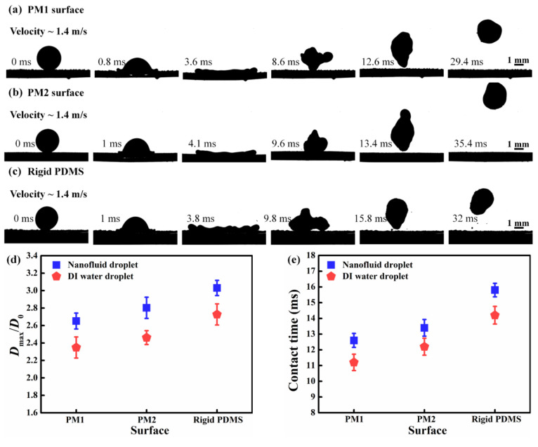
To better understand the mechanism of nanofluid droplet impact on the cold elastic PDMS superhydrophobic surfaces, we analyze the energy conversion of the nanofluid droplet impacting process. As is shown in Figure 7a, the impacting nanofluid droplet with a velocity of 1.4 m/s on the cold elastic PM1 superhydrophobic surface undergoes spreading, recoiling, and rebounding stages. During the nanofluid droplet spreading stage, a downward elastic deformation gradually increases on the cold PDMS elastic surface. The maximum surface deformation of the cold elastic surface occurs at the moment that the nanofluid droplet reaches the maximum spreading diameter Dmax (∼3.6 ms). At this stage, the kinetic energy of the nanofluid droplet is transformed into the surface energy of the nanofluid droplet and the elastic energy of the cold elastic surface and is dissipated by the adhesion energy between the nanofluid droplet and the cold elastic surface. After that, the nanofluid droplet begins to recoil, accompanied by the upward movement of the cold elastic surface. The surface deformation of the cold elastic surface is gradually decreased. During the recoiling stage, the elastic energy of the surface is converted to the kinetic energy of the nanofluid droplet. The superior surface elasticity of the cold PDMS surface shortens the contact time. After that, the nanofluid droplet rebounds off the surface at 12.6 ms with no tiny residual droplets left.
Figure 7.
(a) Selected snapshots of a nanofluid droplet impacting on the cold elastic PM1 superhydrophobic surface (−5 °C) at a velocity of 1.4 m/s. (b) Selected snapshots of a nanofluid droplet impacting on the cold elastic PM2 superhydrophobic surface (−5 °C) at a velocity of 1.4 m/s. (c) Selected snapshots of a nanofluid droplet impacting on the cold rigid PDMS superhydrophobic surface (−5 °C) at a velocity of 1.4 m/s. (d) Comparison of spreading ratio Dmax/D0 of the nanofluid droplet and the DI water droplet on the cold elastic PDMS superhydrophobic surfaces (−5 °C) with various stiffness at a velocity of 1.4 m/s. (e) Contact time of the nanofluid droplet and the DI water droplet on the cold elastic PDMS superhydrophobic surfaces (−5 °C) with various stiffness at a velocity of 1.4 m/s.
When the nanofluid droplet impacts the cold elastic surface with a higher k of 5.21 N/m at the same velocity (1.4 m/s), the lessened surface elasticity leads to a small degree of surface deformation (Figure 7b). Accordingly, the induced elastic energy of the cold elastic PM2 superhydrophobic surface is smaller than that of the cold elastic PM1 superhydrophobic surface. During the nanofluid droplet spreading stage, most proportion of the nanofluid droplet kinetic energy is transformed into the surface energy of the nanofluid droplet. The maximum spreading diameter Dmax of the nanofluid droplet is larger compared to the condition when the nanofluid droplet impacts the cold elastic PM1 superhydrophobic surface. Meanwhile, the increased spreading diameter of the nanofluid droplet enhances the heat conduction from the nanofluid droplet to the cold elastic surface, inducing an elevated adhesion energy. During the droplet rebounding period, the decreased elastic energy and the elevated adhesion energy lead to an increase in the contact time. The nanofluid droplet completely detaches from the cold elastic PM2 superhydrophobic surface at 13.4 ms.
For comparison purposes, the nanofluid droplet impacting the cold rigid PDMS superhydrophobic surface is also investigated. As can be seen from Figure 7c, there is no surface elastic deformation on the cold surface during the nanofluid droplet spreading stage. The kinetic energy of the nanofluid droplet is converted into the surface energy of the nanofluid droplet and the adhesion energy. The surface energy of the nanofluid droplet is larger than that of the nanofluid droplet on the cold elastic surface. Besides, there is a small droplet residue left on the cold rigid PDMS surface at 15.8 ms. This might be ascribed to the increased heat conduction and increased adhesion energy between the nanofluid droplet and the cold rigid surface, whereas the nanofluid droplet can completely detach from the cold elastic PM1 and PM2 superhydrophobic surfaces without residual droplet left, which confirms that the introduction of surface elasticity can significantly improve the water-repellency of the cold surface.
The nanofluid droplet impact dynamics on the cold elastic PDMS surface are characterized by the spreading ratio Dmax/D0 and the contact time. As depicted in Figure 7d, the nanofluid droplet on the cold rigid PDMS superhydrophobic surface shows the largest spreading ratio Dmax/D0 of (∼3.0), which is comparable with the spreading ratio Dmax/D0 of the nanofluid droplet on the cold N surface (∼2.9). With the increase of surface elasticity, the nanofluid droplet spreading ratio Dmax/D0 decreases from ∼2.8 (on the cold elastic PM2 superhydrophobic surface) to ∼2.7 (on the cold elastic PM1 superhydrophobic surface). Moreover, surface elasticity governs the contact time reduction, further accelerating the nanofluid droplet to detach from the cold surface. As can be seen in Figure 7e, the contact time of the nanofluid droplet on the cold elastic PM2 superhydrophobic surface is 20% shorter than that on the cold rigid PDMS superhydrophobic surface. Compared with the nanofluid droplet on the cold MN125 (contact time ∼15.9 ms), the nanofluid droplet on the cold elastic PM1 superhydrophobic surface possesses the shortest contact time (∼12.6 ms), indicating that the surface elasticity can effectively shorten the contact time of the nanofluid droplet. Furthermore, the spreading ratio Dmax/D0 and contact time of the DI water droplet are also shown in Figure 6e, which are much smaller than those of the nanofluid droplet on the cold elastic PDMS superhydrophobic surface under the same experimental conditions.
3.5. Effect of the Nanofluid Droplet Impact Velocity on the Cold Rigid and Elastic Superhydrophobic Surfaces
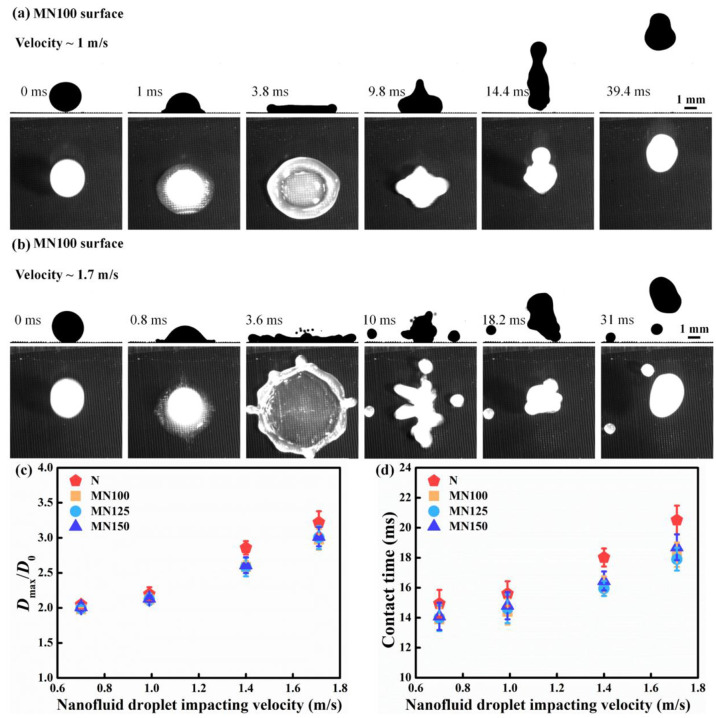
Despite the surface structure and surface stiffness, the impact velocity is also a key factor that influences the impacting behavior of the nanofluid droplet. Figure 8 presents the impacting process of a nanofluid droplet on the cold MN100 superhydrophobic Cu surface at different impacting velocities. As shown in Figure 8a, when the impacting velocity is 1 m/s, the spreading nanofluid droplet is surrounded by an edge bump. Then the nanofluid droplet detaches from the cold MN100 surface with an elongated shape at 14.4 ms. At a higher impacting velocity of 1.7 m/s (Figure 8b), the nanofluid droplet spreads and breaks into several tiny droplets from the edge bump of the spreading circle at 10 ms (see the top view snapshots in Figure 8b), owing to the elevated kinetic energy of the nanofluid droplet. The number of tiny breakup nanofluid droplets is increased with the increase of nanofluid droplet impacting velocity. During the nanofluid droplet rebounding period, these tiny breakup droplets cannot detach from the surface. As presented in Figure 8c,d, the spreading ratio Dmax/D0 of the nanofluid droplet on the cold rigid superhydrophobic Cu surfaces shows a rising trend with the increase of the impacting velocity, leading to an increased contact time. The nanofluid droplet at an impacting velocity of 1.7 m/s on the cold N superhydrophobic surface exhibits the largest spreading ratio Dmax/D0 (∼3.2) and the longest contact time (∼20.5 ms).
Figure 8.
(a) Selected snapshots of a nanofluid droplet impacting on the cold MN100 superhydrophobic Cu surface (−5 °C) at a velocity of 1 m/s. (b) Selected snapshots of a nanofluid droplet impacting on the cold MN100 superhydrophobic Cu surface (−5 °C) at a velocity of 1.7 m/s. (c) Spreading ratio Dmax/D0 of the nanofluid droplet on the cold MN100 superhydrophobic Cu surface (−5 °C) with the impacting velocity ranging from 0.7 to 1.4 m/s. (e) Contact time of the nanofluid droplet on the cold MN100 superhydrophobic Cu surface (−5 °C) with the impacting velocity ranging from 0.7 to 1.4 m/s.
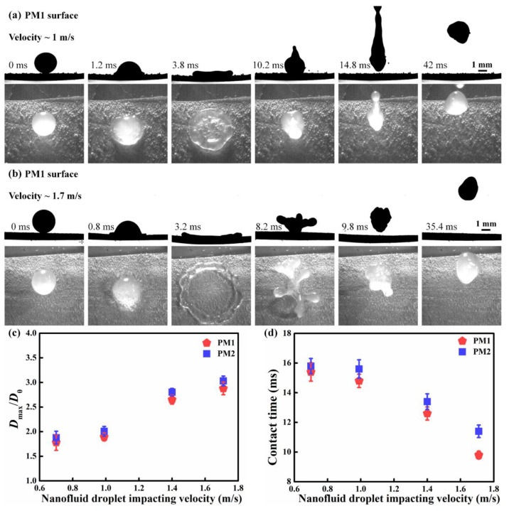
The impacting nanofluid droplet exhibits a contact time reduction and a splash delay on the cold elastic PM1 superhydrophobic surface when compared to the nanofluid droplet on the cold rigid superhydrophobic Cu surface. As can be seen in Figure 9a, at a velocity of 1 m/s, the contact time of the nanofluid droplet is 14.8 ms, which is smaller than that of the nanofluid droplet on the cold MN100 surface with the same velocity. Further increasing the nanofluid droplet impact velocity to 1.7 m/s (Figure 9b) significantly increases the kinetic energy of the nanofluid droplet. When the nanofluid droplet impacts on the cold elastic surface, the deformation degree of the cold elastic surface is significantly increased, leading to an increased surface elastic energy. The increased surface elastic energy further accelerates the nanofluid droplet to rebound off the cold elastic surface. Interestingly, even at the high impact velocity, the entire nanofluid droplet can bounce off the cold elastic surface without tiny droplets breaking. Figure 9c,d gives the spreading ratio Dmax/D0 and contact time of the nanofluid droplet on the cold elastic PM1 and PM2 superhydrophobic surfaces with varied impacting velocities. It can be seen that when the impact velocity rises from 0.7 to 1.7 m/s, the nanofluid droplet on the cold elastic surface shows a significantly decreased contact time even with an increased spreading ratio. For example, when on the cold elastic PM1 superhydrophobic surface at a velocity of 1.7 m/s, the nanofluid droplet shows the shortest contact time of ∼9.8 ms, which is much less than that of the nanofluid droplet on the cold rigid superhydrophobic surfaces. These results validate that the introduction of surface elasticity can effectively reduce the contact time and suppress nanofluid droplet splashing at a high impacting velocity.
Figure 9.
(a) Selected snapshots of a nanofluid droplet impacting on the cold elastic PM1 superhydrophobic surface (−5 °C) at a velocity of 1 m/s. (b) Selected snapshots of a nanofluid droplet impacting on the cold elastic PM1 superhydrophobic surface (−5 °C) at a velocity of 1.7 m/s. (c) Spreading ratio Dmax/D0 of the nanofluid droplet on the cold elastic PM1 and PM2 superhydrophobic surfaces (−5 °C) with the impacting velocity ranging from 0.7 to 1.4 m/s. (e) Contact time of the nanofluid droplet on the cold elastic PM1 and PM2 superhydrophobic surfaces (−5 °C) with the impact velocity ranging from 0.7 to 1.4 m/s.
4. Conclusions
In summary, we developed a rigid superhydrophobic Cu surface and an elastic PDMS superhydrophobic surface to repel the impacting nanofluid droplet from the cold substrate. The introduction of a hierarchically micro/nanostructured micropillar array induces superior surface superhydrophobicity. The trapped air pockets between the micropillar array trigger low heat conduction between the nanofluid droplet and the cold surface, further leading to the rapid detachment of the nanofluid droplet without ice crystal formation. With a larger edge-to-edge spacing of micropillars array on the cold rigid superhydrophobic Cu surface in a limited range, the smaller is the spreading ratio Dmax/D0 and the smaller is the contact time of the nanofluid droplet. Meanwhile, benefiting from the surface elasticity of the cold PDMS elastic surface, the nanofluid droplet can completely rebound off the cold surface without tiny droplets left. With a lower surface stiffness (k ∼ 0.65 N/m), the increased degree of surface elastic deformation induces an elevated elastic energy and decreased adhesion energy, which further shortens the contact time. Furthermore, at a higher impacting velocity, the nanofluid droplet on the cold elastic surface shows a significantly reduced contact time and the splash suppression, when compared to the nanofluid droplet on the cold rigid superhydrophobic Cu surface. We envision this work could provide potential for a wide range of applications including anti-icing, deicing, and self-cleaning.
Acknowledgments
The authors acknowledge the financial support from the National Natural Science Foundation of China (52276071 and U2241252).
Supporting Information Available
The Supporting Information is available free of charge at https://pubs.acs.org/doi/10.1021/acsomega.3c10409.
More details regarding the dimension parameter of the micropillars array on the hierarchical micro/nanostructured superhydrophobic Cu surface; detailed information regarding the visualized experimental setup for nanofluid droplet impacting on the as-fabricated cold surface; a description of the effect of nanoparticle concentration on the nanofluid droplet impacting dynamics on the cold MN100 surface (PDF)
Author Contributions
† Chenlu Qian and Xiaoyang Li contributed equally to this work.
The authors declare no competing financial interest.
Supplementary Material
References
- Bendel W. B.; Paton D. A Review of the Effect of Ice Storms on the Power Industry. Journal of Applied Meteorology and Climatology 1981, 20 (12), 1445–1449. . [DOI] [Google Scholar]
- Lynch F. T.; Khodadoust A. Effects of Ice Accretions on Aircraft Aerodynamics. Progress in Aerospace Sciences 2001, 37 (8), 669–767. 10.1016/S0376-0421(01)00018-5. [DOI] [Google Scholar]
- Kraj A. G.; Bibeau E. L. Phases of Icing on Wind Turbine Blades Characterized by Ice Accumulation. Renewable Energy 2010, 35 (5), 966–972. 10.1016/j.renene.2009.09.013. [DOI] [Google Scholar]
- Lian W.; Xuan Y. Experimental Investigation on a Novel Aero-Engine Nose Cone Anti-Icing System. Applied Thermal Engineering 2017, 121, 1011–1021. 10.1016/j.applthermaleng.2017.04.160. [DOI] [Google Scholar]
- Stebbins S. J.; Loth E.; Broeren A. P.; Potapczuk M. Review of Computational Methods for Aerodynamic Analysis of Iced Lifting Surfaces. Progress in Aerospace Sciences 2019, 111, 100583. 10.1016/j.paerosci.2019.100583. [DOI] [Google Scholar]
- Latham J.; Saunders C. P. R. Aggregation of Ice Crystals in Strong Electric Fields. Nature 1964, 204 (4965), 1293–1294. 10.1038/2041293a0. [DOI] [Google Scholar]
- Chang T.; Zhao G. Ice Inhibition for Cryopreservation: Materials, Strategies, and Challenges. Advanced Science 2021, 8 (6), 2002425. 10.1002/advs.202002425. [DOI] [PMC free article] [PubMed] [Google Scholar]
- Liu Y.; Wu Y.; Liu Y.; Xu R.; Liu S.; Zhou F. Robust Photothermal Coating Strategy for Efficient Ice Removal. ACS Appl. Mater. Interfaces 2020, 12 (41), 46981–46990. 10.1021/acsami.0c13367. [DOI] [PubMed] [Google Scholar]
- Ma W.; Li Y.; Chao C. Y. H.; Tso C. Y.; Huang B.; Li W.; Yao S. Solar-Assisted Icephobicity down to −60°C with Superhydrophobic Selective Surfaces. Cell Reports Physical Science 2021, 2 (3), 100384. 10.1016/j.xcrp.2021.100384. [DOI] [Google Scholar]
- Niu W.; Chen G. Y.; Xu H.; Liu X.; Sun J. Highly Transparent and Self-Healable Solar Thermal Anti-/Deicing Surfaces: When Ultrathin MXene Multilayers Marry a Solid Slippery Self-Cleaning Coating. Adv. Mater. 2022, 34 (10), 2108232. 10.1002/adma.202108232. [DOI] [PubMed] [Google Scholar]
- Li T.; Ibáñez-Ibáñez P. F.; Håkonsen V.; Wu J.; Xu K.; Zhuo Y.; Luo S.; He J.; Zhang Z. Self-Deicing Electrolyte Hydrogel Surfaces with Pa-Level Ice Adhesion and Durable Antifreezing/Antifrost Performance. ACS Appl. Mater. Interfaces 2020, 12 (31), 35572–35578. 10.1021/acsami.0c06912. [DOI] [PMC free article] [PubMed] [Google Scholar]
- Shi Z.; Kang Z.; Xie Q.; Tian Y.; Zhao Y.; Zhang J. Ultrasonic Deicing Efficiency Prediction and Validation for a Flat Deicing System. Applied Sciences 2020, 10 (19), 6640. 10.3390/app10196640. [DOI] [Google Scholar]
- Li Y.; Shen H.; Guo W. Simulation and Experimental Study on the Ultrasonic Micro-Vibration De-Icing Method for Wind Turbine Blades. Energies 2021, 14 (24), 8246. 10.3390/en14248246. [DOI] [Google Scholar]
- Zhuo Y.; Xiao S.; Håkonsen V.; He J.; Zhang Z. Anti-Icing Ionogel Surfaces: Inhibiting Ice Nucleation, Growth, and Adhesion. ACS Materials Lett. 2020, 2 (6), 616–623. 10.1021/acsmaterialslett.0c00094. [DOI] [Google Scholar]
- Azimi Yancheshme A.; Momen G.; Jafari Aminabadi R. Mechanisms of Ice Formation and Propagation on Superhydrophobic Surfaces: A Review. Adv. Colloid Interface Sci. 2020, 279, 102155. 10.1016/j.cis.2020.102155. [DOI] [PubMed] [Google Scholar]
- Zhou X.; Sun Y.; Liu J. Designing Anti-Icing Surfaces by Controlling Ice Formation. Advanced Materials Interfaces 2021, 8 (17), 2100327. 10.1002/admi.202100327. [DOI] [Google Scholar]
- Milles S.; Soldera M.; Voisiat B.; Lasagni A. F. Fabrication of Superhydrophobic and Ice-Repellent Surfaces on Pure Aluminium Using Single and Multiscaled Periodic Textures. Sci. Rep 2019, 9 (1), 13944. 10.1038/s41598-019-49615-x. [DOI] [PMC free article] [PubMed] [Google Scholar]
- Wang D.; Sun Q.; Hokkanen M. J.; Zhang C.; Lin F.-Y.; Liu Q.; Zhu S.-P.; Zhou T.; Chang Q.; He B.; Zhou Q.; Chen L.; Wang Z.; Ras R. H. A.; Deng X. Design of Robust Superhydrophobic Surfaces. Nature 2020, 582 (7810), 55–59. 10.1038/s41586-020-2331-8. [DOI] [PubMed] [Google Scholar]
- Dong Z.; Vuckovac M.; Cui W.; Zhou Q.; Ras R. H. A.; Levkin P. A. 3D Printing of Superhydrophobic Objects with Bulk Nanostructure. Adv. Mater. 2021, 33 (45), 2106068. 10.1002/adma.202106068. [DOI] [PMC free article] [PubMed] [Google Scholar]
- Boinovich L. B.; Emelyanenko K. A.; Emelyanenko A. M. Superhydrophobic versus SLIPS: Temperature Dependence and the Stability of Ice Adhesion Strength. J. Colloid Interface Sci. 2022, 606, 556–566. 10.1016/j.jcis.2021.08.030. [DOI] [PubMed] [Google Scholar]
- Feng X.; Zhang X.; Tian G. Recent Advances in Bioinspired Superhydrophobic Ice-Proof Surfaces: Challenges and Prospects. Nanoscale 2022, 14 (16), 5960–5993. 10.1039/D2NR00964A. [DOI] [PubMed] [Google Scholar]
- Kulinich S. A.; Farhadi S.; Nose K.; Du X. W. Superhydrophobic Surfaces: Are They Really Ice-Repellent?. Langmuir 2011, 27 (1), 25–29. 10.1021/la104277q. [DOI] [PubMed] [Google Scholar]
- Teisala H.; Butt H.-J. Hierarchical Structures for Superhydrophobic and Superoleophobic Surfaces. Langmuir 2019, 35 (33), 10689–10703. 10.1021/acs.langmuir.8b03088. [DOI] [PubMed] [Google Scholar]
- Liu S.; Zhang X.; Seeger S. Solvent-Free Fabrication of Flexible and Robust Superhydrophobic Composite Films with Hierarchical Micro/Nanostructures and Durable Self-Cleaning Functionality. ACS Appl. Mater. Interfaces 2019, 11 (47), 44691–44699. 10.1021/acsami.9b15318. [DOI] [PubMed] [Google Scholar]
- Tang Y.; Yang X.; Li Y.; Lu Y.; Zhu D. Robust Micro-Nanostructured Superhydrophobic Surfaces for Long-Term Dropwise Condensation. Nano Lett. 2021, 21 (22), 9824–9833. 10.1021/acs.nanolett.1c01584. [DOI] [PubMed] [Google Scholar]
- Wang L.; Gong Q.; Zhan S.; Jiang L.; Zheng Y. Robust Anti-Icing Performance of a Flexible Superhydrophobic Surface. Adv. Mater. 2016, 28 (35), 7729–7735. 10.1002/adma.201602480. [DOI] [PubMed] [Google Scholar]
- Wang G.; Shen Y.; Tao J.; Luo X.; Zhang L.; Xia Y. Fabrication of a Superhydrophobic Surface with a Hierarchical Nanoflake-Micropit Structure and Its Anti-Icing Properties. RSC Adv. 2017, 7 (16), 9981–9988. 10.1039/C6RA28298A. [DOI] [Google Scholar]
- Bengaluru Subramanyam S.; Kondrashov V.; Rühe J.; Varanasi K. K. Low Ice Adhesion on Nano-Textured Superhydrophobic Surfaces under Supersaturated Conditions. ACS Appl. Mater. Interfaces 2016, 8 (20), 12583–12587. 10.1021/acsami.6b01133. [DOI] [PubMed] [Google Scholar]
- Jung Y. C.; Bhushan B. Mechanically Durable Carbon Nanotube-Composite Hierarchical Structures with Superhydrophobicity, Self-Cleaning, and Low-Drag. ACS Nano 2009, 3 (12), 4155–4163. 10.1021/nn901509r. [DOI] [PubMed] [Google Scholar]
- Koch K.; Bhushan B.; Jung Y. C.; Barthlott W. Fabrication of Artificial Lotus Leaves and Significance of Hierarchical Structure for Superhydrophobicity and Low Adhesion. Soft Matter 2009, 5 (7), 1386–1393. 10.1039/b818940d. [DOI] [Google Scholar]
- Weisensee P. B.; Tian J.; Miljkovic N.; King W. P. Water Droplet Impact on Elastic Superhydrophobic Surfaces. Sci. Rep 2016, 6 (1), 30328. 10.1038/srep30328. [DOI] [PMC free article] [PubMed] [Google Scholar]
- Vasileiou T.; Gerber J.; Prautzsch J.; Schutzius T. M.; Poulikakos D. Superhydrophobicity Enhancement through Substrate Flexibility. Proc. Natl. Acad. Sci. U.S.A. 2016, 113 (47), 13307–13312. 10.1073/pnas.1611631113. [DOI] [PMC free article] [PubMed] [Google Scholar]
- Markodimitrakis I. E.; Sema D. G.; Chamakos N. T.; Papadopoulos P.; Papathanasiou A. G. Impact of Substrate Elasticity on Contact Angle Saturation in Electrowetting. Soft Matter 2021, 17 (16), 4335–4341. 10.1039/D0SM02281K. [DOI] [PMC free article] [PubMed] [Google Scholar]
- Zimmermann J.; Reifler F. A.; Fortunato G.; Gerhardt L.-C.; Seeger S. A Simple, One-Step Approach to Durable and Robust Superhydrophobic Textiles. Adv. Funct. Mater. 2008, 18 (22), 3662–3669. 10.1002/adfm.200800755. [DOI] [Google Scholar]
- Mangili S.; Antonini C.; Marengo M.; Amirfazli A. Understanding the Drop Impact Phenomenon on Soft PDMS Substrates. Soft Matter 2012, 8 (39), 10045–10054. 10.1039/c2sm26049b. [DOI] [Google Scholar]
- Pepper R. E.; Courbin L.; Stone H. A. Splashing on Elastic Membranes: The Importance of Early-Time Dynamics. Phys. Fluids 2008, 20 (8), 082103. 10.1063/1.2969755. [DOI] [Google Scholar]
- Chen R.-H.; Phuoc T. X.; Martello D. Effects of Nanoparticles on Nanofluid Droplet Evaporation. Int. J. Heat Mass Transfer 2010, 53 (19), 3677–3682. 10.1016/j.ijheatmasstransfer.2010.04.006. [DOI] [Google Scholar]
- Aksoy Y. T.; Liu L.; Abboud M.; Vetrano M. R.; Koos E. Role of Nanoparticles in Nanofluid Droplet Impact on Solid Surfaces. Langmuir 2023, 39 (1), 12–19. 10.1021/acs.langmuir.2c02578. [DOI] [PMC free article] [PubMed] [Google Scholar]
- Zhang H.; Zhao Y.; Fang W.; Zhang C.; Zhu F.; Jin L.; Yang C. Active Control of the Freezing Process of a Ferrofluid Droplet with Magnetic Fields. Applied Thermal Engineering 2020, 176, 115444. 10.1016/j.applthermaleng.2020.115444. [DOI] [Google Scholar]
- Zarasvand K. A.; Nazemi A.; Lahiri S. K.; Tetreault A.; Milani A. S.; Bender T. P.; Golovin K. Skin-Inspired Nanofluid-Filled Surfaces with Tunable Icephobic, Photothermal, and Energy Absorption Properties. Adv. Funct. Mater. 2023, 33 (46), 2305517. 10.1002/adfm.202305517. [DOI] [Google Scholar]
- Rubbi F.; Das L.; Habib K.; Aslfattahi N.; Saidur R.; Rahman M. T. State-of-the-Art Review on Water-Based Nanofluids for Low Temperature Solar Thermal Collector Application. Sol. Energy Mater. Sol. Cells 2021, 230, 111220. 10.1016/j.solmat.2021.111220. [DOI] [Google Scholar]
- Patil N. D.; Bhardwaj R.; Sharma A. Droplet Impact Dynamics on Micropillared Hydrophobic Surfaces. Experimental Thermal and Fluid Science 2016, 74, 195–206. 10.1016/j.expthermflusci.2015.12.006. [DOI] [Google Scholar]
- Kim S. H.; Lee G.; Kim H.; Kim M. H. Leidenfrost Point and Droplet Dynamics on Heated Micropillar Array Surface. Int. J. Heat Mass Transfer 2019, 139, 1–9. 10.1016/j.ijheatmasstransfer.2019.04.093. [DOI] [Google Scholar]
- Mahbubul I. M.; Elcioglu E. B.; Amalina M. A.; Saidur R. Stability, Thermophysical Properties and Performance Assessment of Alumina-Water Nanofluid with Emphasis on Ultrasonication and Storage Period. Powder Technol. 2019, 345, 668–675. 10.1016/j.powtec.2019.01.041. [DOI] [Google Scholar]
- Hemmat Esfe M.; Saedodin S.; Mahian O.; Wongwises S. Thermal Conductivity of Al2O3/Water Nanofluids. J. Therm Anal Calorim 2014, 117 (2), 675–681. 10.1007/s10973-014-3771-x. [DOI] [Google Scholar]
- Mukherjee S.; Mishra P. C.; Chaudhuri P.; Chakrabarty S. Experimental Investigation on Thermal Conductivity of Surfactant-Less Aluminium Oxide (Al2O3) in Water Nanofluid Using Acoustic Velocity Measurements. Curr. Sci. 2021, 121 (8), 1032. 10.18520/cs/v121/i8/1032-1038. [DOI] [Google Scholar]
- Park S. C.; Kim M. H.; Wongwises S.; Yu D. I.; Ahn H. S. Explosive Lift-off Triggering Mechanism on a Surface with Micropillar Arrays: Liquid-Vapor Interface Behavior between Micropillars during Drop Impingement. Applied Thermal Engineering 2022, 201, 117739. 10.1016/j.applthermaleng.2021.117739. [DOI] [Google Scholar]
- Zhang S.; Zhang L.-Z. Bouncing Modes and Heat Transfer of Impacting Droplets on Textured Superhydrophobic Surfaces. Int. J. Heat Mass Transfer 2024, 219, 124875. 10.1016/j.ijheatmasstransfer.2023.124875. [DOI] [Google Scholar]
Associated Data
This section collects any data citations, data availability statements, or supplementary materials included in this article.


