Abstract
Indoor exposure to outdoor pollutants adversely affects health, varying with building dimensions and particularly ventilation that have critical role on their indoor dispersion. This study assesses the impact of outdoor air on indoor air quality in a child care center. Computational fluid dynamics was utilized to analyze the dispersion of particulate matter, with a specific focus on window screens featuring 6 distinct pore sizes ranging from 0.8 mm to 2 mm and 2 different thicknesses of 0.5 mm and 0.1 mm. Results indicate that the presence of a window screen offers significant advantages in controlling particle infiltration compared to scenarios without a screen, as larger particles tend to pass directly through the window within the breathing zone. The scenario without window screens minimizes pressure drop but lacks enhanced particle capture capabilities. However, for effective particle reduction, the window screen with a pore size of 0.8 mm (R0.8T2) and a thickness of 0.5 mm proves to be the most beneficial, achieving the particle filtering efficiency of approximately 54.16%, while the larger window screen with a pore size of 2 mm and a thickness of 1 mm exhibits the lowest efficiency at about 23.85%. Nonetheless, screens with very small sizes are associated with a high-pressure drop, impacting energy efficiency, and overall window performance. Larger pores with smaller thicknesses (0.5 mm) reduced particle count by approximately 45.97%. Therefore, the significance of window screen thickness beyond pore size for particle reduction efficiency is highlighted, emphasizing screens’ role in indoor air quality and health protection.
Keywords: CFD, indoor air quality, natural ventilation, window screen
Introduction
The deterioration of the atmospheric environment in urban areas is a prominent environmental issue in numerous countries intensified as a consequence of accelerated industrialization, urbanization, and the proliferation of motor vehicles, all driven by human activities. 1 This has led to human-caused air pollution becoming a significant global public health threat, responsible for approximately 4.2 million premature deaths worldwide per year in 2019. 2 Among air pollutants, particulate matter (PM), specifically PM2.5, poses a significant health concern due to its small size and ability to penetrate human lungs and bronchial passages.3,4
In developed countries, people are dedicating an increasing amount of their time, typically ranging from 80% to 90%, to various indoor environments.5,6 This highlights the significance of indoor air quality on public health, particularly for vulnerable groups, such as children and the elderly.7 -9 Given that most people prefer to spend their time indoors, it is important to understand the PM levels in the indoor air.
Preschools and childcare centers serve as the primary indoor environments where young children spend a significant portion of the day. The activities undertaken by children, such as playing with toys on carpets and bedcovers, have a considerable impact on the concentration of air pollutants.10,11 It is critical to increase the awareness that children are physiologically more prone to the negative health repercussions of air pollution compared to adults. This heightened susceptibility is due to their higher volume of air intake relative to their body mass and the ongoing development of their lungs.12,13
Indoor air quality (IAQ) is primarily influenced by building attributes, such as ventilation, building location, cleaning practices, and the operability of windows. Achieving improved indoor air quality is accomplished by ventilating rooms with external air.14 -16 There are 3 main ventilation methods: natural, mechanical, and hybrid (mixed mode). 17 Among these, natural ventilation is the most efficient and environmentally friendly due to its reliance on the elements and the presence of large openings. 18 However, controlling the natural ventilation can be challenging and requires careful planning.
Air filtration methods have demonstrated both high particle removal efficiency and relatively low air resistance. In previous studies, researchers have noted that window screens, acting as supportive substrates, can effectively block outdoor PM2.5 from entering indoor spaces when windows are open, especially during natural ventilation.19 -22 Notably, the high-efficiency particulate air filter, renowned for its ability to remove 99.97% of particles measuring ⩾0.3 μm in diameter, stands out as a highly effective technology for enhancing IAQ. 23 Despite high particle removal efficiency achieved with these filters, a significant increase in energy consumption in heating, ventilation, and air-conditioning (HVAC) systems can be brought about by the large air resistance. 24
In previous studies, the exploration of window screen properties involved a combination of experimental investigations and modeling analyses. It was reported that nanofiber filters were recommended as a viable option for use as window screens to prevent outdoor PM2.5 from entering indoor spaces through natural ventilation during the open window.24 -26 An aspect to consider is that nanofiber filters may be less reusable due to the challenge of cleaning PM particles deeply embedded within the nanofiber structure. 27 Another type of air filtration system is the porous membrane filter, typically constructed by creating minute pores within a solid substrate or a thin film, meticulously designed to target larger PM particles. 28 In addition to pore size, the filtration process benefits from various essential mechanisms, including inertial impaction, interception, Brownian motion, gravitational settling, and electrostatic forces. 29 Previous research has demonstrated the impressive performance of isoporous through-hole membrane filters, with exceptional filtration efficiency maintained while achieving a low pressure drop. 27 Furthermore, the ease of maintenance is provided by these filters, allowing for convenient cleaning through simple wipe with a damp cloth or a gentle spray with water. Additionally, they are designed for multiple uses, making them a cost-effective and eco-friendly choice. 27
Computational fluid dynamics (CFD) is a well-established tool for assessing and understanding ventilation and pollutant dispersion patterns across various scales in the urban environment. 30 CFD simulations have been extensively applied in various fields, including the food industry, biotechnology processes, agro-environmental applications, and the design of indoor and outdoor environments.31 -35 The CFD models are widely used for analysis of airflow, temperature, and contaminant distributions in a diverse range of applications, providing detailed thermal and contaminant data through simulation, particularly emphasizing natural ventilation scenarios.36 -38
In CFD models, particle dispersion can be approached via 2 methods: Eulerian and Lagrangian. Eulerian methods treat particles as a continuous medium, deriving particle concentration fields from conservation equations to understand dispersion broadly. In contrast, the Lagrangian discrete phase model meticulously tracks individual particle dynamics and is particularly effective for modeling dust dispersion.39,40 Therefore, in this study, the discrete phase model was selected to conduct the investigation of particle dispersion.
The primary objective of this study is to perform a numerical analysis exploring the impact of outdoor air on indoor air characteristics, examining the dispersion of particulate matter. Additionally, the study aims to assess the influence of window screens with different pore sizes and thicknesses on the air characteristics in a childcare center using CFD. The finding can assist childcare centers located near small scale industrial areas in formulating plans to implement suitable measures for controlling indoor air pollutant exposure, with a particular focus on the use of window screens.
Materials and Methods
Study area
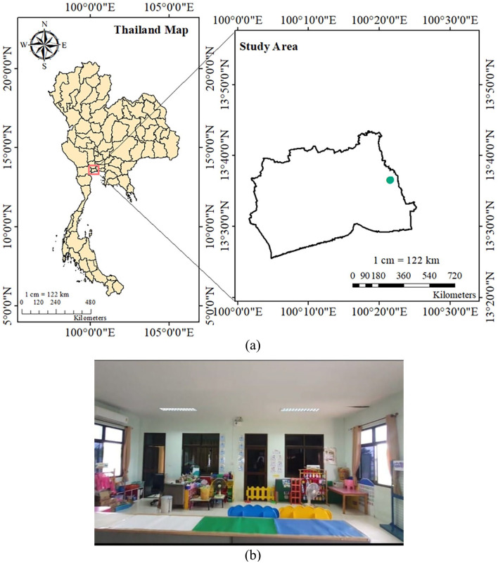
The research site was located in Samut Sakhon province, approximately 48 km away from Bangkok, as illustrated in Figure 1a. This area is known for its substantial metal smelting industry, with the childcare center (Figure 1b) situated about 1 km from the small scale industrial area.
Figure 1.
Study area (a); childcare center (b).
Data collection
The meteorological data, including various wind speeds used in this study, were collected from the King Mongkut’s University of Technology Thonburi meteorological station during the cool and hot dry seasons. 41 During cool dry periods: November 17th, 2022. During this period, there was about 20-40 mm of rain with a relative humidity of 70%-75% and an average temperature of 29.0°C ± 5.8°C. In contrast, the hot dry season in February experienced 10-20 mm of rain, lower relative humidity (65%-70%), and a higher average temperature of 30.2°C ± 5.9°C. 42 These measurements were recorded over an 8-hour (07.00 AM-03.00 PM) duration during each period.
Case description
The simulation was conducted using Autodesk inventor 2020 and ANSYS 2021 R2. The study primarily examined the horizontal sliding window type, a prevalent configuration in this study area where windows are commonly fully open. During this period, 2 scenarios were investigated: one with the window fully open without a window screen, and the other with the window fully open while using a window screen.
Geometry design
In CFD simulations, the generation of a highly detailed geometric model of the simulated area is essential before the simulation mesh is created. This study, specifically, focused on a selected room within the childcare center, as depicted in Figure 2a. The arrangement of window screen placement is illustrated in Figure 2b, presenting a side view of the window where the screen will be installed on the horizontal sliding window type. The window screen examined in this study closely mirrors an insect screen. The configuration of the air window screen is established through the porous jump method. 43
Figure 2.
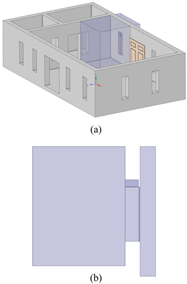
Isometric view of (a) the observation room; (b) the side view window with window screen.
In this model, the thin perforated plate is represented as a porous medium with a limited thickness (equation (1)). The decrease in pressure arises from a blend of Darcy’s law and an extra inertial loss factor. 44
| (1) |
where, represent viscosity and density of air, C2 stands for the pressure-jump coefficient, denotes the velocity perpendicular to the porous plate, and ∆m represents the plate’s thickness.
Meshing strategies
The constructed room’s geometry was exported to ANSYS, where the model underwent numerical discretization through mesh generation. The computational domain had the dimensions of the classroom, serving as the primary focus of the study (3.75 m × 2.68 m × 2.96 m). Furthermore, the assessment of the mesh geometric quality in this study was achieved by examining parameters related to orthogonal quality and skewness (Figure 3) with mesh details presented in Table 1. The computation grid resolution, with varying element sizes set to 0.03 m for the filter, 0.065 m for the environment room, and 0.06 m for the window zone, resulted in mesh quality showing acceptable skewness (0.25-0.50) and very good orthogonality (0.70-0.95). In this study, the grid is first constructed in a horizontal plane before being extended vertically. This method provides a high level of control over the shapes and sizes of the individual cells. 45 The structured grid was generated in ANSYS Mesh using the sweep method, along with edge sizing applied to parallel corresponding edges. These parameters were rated on a scale ranging from 0 to 1, where values higher values closer to 1 indicate better orthogonal quality and lower values closer to 0 suggest improved skewness. 46
Figure 3.
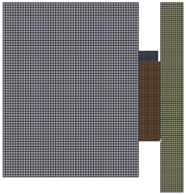
The mesh used for the simulation.
Table 1.
The details of the mesh structure.
| Quality | Orthogonal quality | Skewness |
|---|---|---|
| Min | 0.261 | 1.357e-10 |
| Max | 1 | 0.739 |
| Average | 0.730 | 0.269 |
| Standard deviation | 0.120 | 0.120 |
| Nodes | 434265 | 434265 |
| Elements | 22293777 | 2223777 |
Boundary condition
The accuracy of CFD simulations is dependent on the correct configuration of boundary conditions and numerical simulation parameters. 47 Figure 4 depicts the boundary conditions, consisting of a mass flow inlet (Figure 4a) where the primary wind enters perpendicular to the inflow area, with its direction and velocity determined by the inflow area’s boundary conditions. The outlet and wall conditions are illustrated in Figure 4b. For the outflow area, boundary conditions must align with those of the inflow area to ensure conservation of flux within the computational domain. The walls are characterized by the fluid velocity profile near the contact area, determined by y+, a dimensionless value representing the distance between the fluid and the wall and assessing turbulent effects according to the law of walls.48,49
Figure 4.
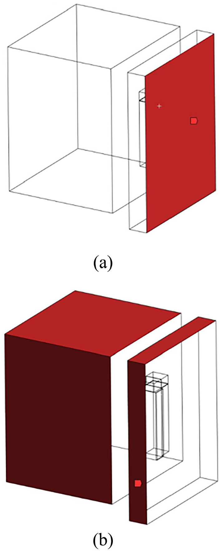
Boundary conditions (a) inlet; (b) outlet and wall.
In Table 2, the numerical parameters utilized in this study were drawn from field data and existing literature,50 -52 with the assumption that the wind velocity and particle velocity were equal. The wind velocity was determined based on the average wind speed over an 8-hour period. In this study, 3 different groups were formed, consisting of round perforated sheets: R0.8T2, R1T2, and R2T3, with each assigned a thickness of 0.5 mm and 1 mm, as shown in Table 3. The open area was reported as a percentage that reflects the extent to which the sheet is occupied by holes. Furthermore, the range of particle diameters employed in this study was set as 1 to 100 µm.
Table 2.
| Parameters | Unit | Values |
|---|---|---|
| Wind velocity (cool dry season) | m/s | 0.791 |
| Wind velocity (hot dry season) | m/s | 1.322 |
| Particle velocity | m/s | 0.791 |
| Particle size (min) | m | 10−8 |
| Particle size (max) | m | 10−6 |
| Air density | kg/m3 | 1.225 |
| Viscosity | kg/ms | 1.789 × 10⁻⁵ |
| Room size | m | 3.75 × 2.68 × 2.96 |
| Window size | m | 1.57 × 0.28 |
Table 3.
Window screen properties.
| Types | Open area (%) | ID | Pore size (D) (mm) | Pitch (C) (mm) | Thickness (Δm) (mm) |
|---|---|---|---|---|---|
| R0.8T2 | 14.51 | A | 0.8 | 2 | 0.5 |
| B | 0.8 | 2 | 1 | ||
| R1T2 | 22.67 | C | 1 | 2 | 0.5 |
| D | 1 | 2 | 1 | ||
| R2T3 | 40.31 | E | 2 | 3 | 0.5 |
| F | 2 | 3 | 1 |
Numerical setup
The numerical setup assumed the continuous phase characterized as air with its flow simulated based on the realizable model, while the dust particles were regarded as the discrete phase, and the trajectory of each particle was computed utilizing the discrete phase model (DPM).
Governing equation
The movement of air is governed by the Navier-Stokes equation, which are given in equation (2) to equation (5)53,54:
| (2) |
| (3) |
| (4) |
| (5) |
where, are static pressure, gas density, gas volume fraction, gas velocity, and gravity acceleration, while is the viscous stress tensor, respectively. μ, µt, k, I, and F are the molecular viscosity, turbulent viscosity, turbulent kinetic energy unit tensor, and volumetric momentum transfer rate between particles and gas phases. Furthermore, in this study, the standard k − ε model is widely employed as the predominant turbulence model (equations (6)-(9)).
| (6) |
| (7) |
| (8) |
| (9) |
where , are turbulent dissipation rate and turbulent production with the following values for the constant: are set to 0.09, 1.44, 19.92, 1, and 1.3.
Discrete Phase Model (DPM)
The Euler-Lagrange model approach within the DPM is utilized for tracking particle movements. The continuous phase is coupled with the k-ε turbulence model to facilitate calculations alongside the discrete phase. 55 Based on the DPM each particle was traced during the whole dispersion process.
In accordance with Newton’s second law of motion, the movement of particles within the airflow field can be described as in equation (10):
| (10) |
where, represents the particle mass; signifies particle velocity; is the gravitational force, while represents drag force as in equation (11):
| (11) |
where, is particle velocity and signifies particle diameter. Additionally, represents the drag coefficient that can be considered as in equation (12):
| (12) |
where, and represent constants relevant to smooth spherical particles within multiple Reynolds number ( ranges while µ stands for dynamic viscous as in equation (13).51,52
| (13) |
Mass imbalance
Due to the limited availability of experimental data, the mass imbalance method was employed in this study. In a previous study, the mass imbalance method was considered an indicator of result accuracy.56 -59 The mass imbalance in this study serves as a measure of the simulation error, determined by comparing the mass flow rates entering and leaving the computational domain. Subsequently, the results were examined and compared based on the mass imbalance factor at the conclusion of the modeling practice. A recommended practice is to target solution imbalances of less than 1%, as indicated by equation (14). 60
| (14) |
Window screen efficiency
The window screen efficiency is defined in equation (15) 61
| (15) |
where, represents the window screen efficiency and and represent the number of particles at the inlet and outlet.
Result and Discussion
Comparison of pressure distribution between without and with a window screen
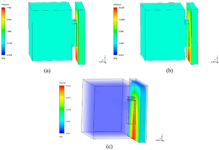
In this study, a pressure outlet boundary condition was specified at the air outlet. Within this configuration, static pressure is set as a constant at this boundary, and all other flow properties are derived from the internal flow. The careful management of pressure is considered important for regulating the transfer of airborne contaminants between the indoor and outdoor spaces of the building. 62 The pressure distribution during the full open window condition without the presence of a window screen is depicted in Figure 5. Notably, high pressure is observed at the inlet, where it is recorded at 7.184 Pa with a pressure drop to 0.176 Pa (Figure 5a). However, during the hot dry season (Figure 5b), the pressure value significantly, reaching 20.287 Pa. A more substantial pressure drop of 0.481 Pa is also noted during this season. The fluctuations in indoor pressure, after air passes through natural ventilation in this study, are linked to the principles of the Bernoulli equation which suggests that a pressure disparity emerges when the airflow channel undergoes narrowing or experiences alterations in its geometry. 63 Furthermore, Window Screen E was selected to show an overview of pressure distribution (Figure 5c) during cool dry season. Its inclusion offers a visual representation of the associated pressure values, allowing for a comparison of different pressure values with and without the window screen. In the realm of natural ventilation, these pressure variations play a pivotal role in shaping the broader dynamics of airflow within the indoor environment. 64 Significantly, this investigation reveals a dynamic in which the indoor air pressure is reduced, resulting in the creation of a negative pressure differential compared to the outdoor air pressure. 65 This imbalance, as unveiled in this study, leads to the infiltration of outdoor air into the building through the window. It should be noted that the high pressure drop across a window screen is directly related to 2 key factors: velocity profile and filter thickness. 25 With an increased pressure drop, greater removal efficiency is achieved, 66 reinforcing the significance of the filter’s role in maintaining indoor air quality.
Figure 5.
Pressure distribution without window screen: (a) cool dry season, (b) hot dry season, and (c) with Window Screen E.
Comparison of velocity distribution between without and with a window screen
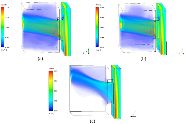
The velocity distribution across the domain is presented in Figure 6. A peak velocity of around 3.219 m/s was documented (Figure 6a), signifying the airflow speed in the absence of a window screen. In contrast, a notably higher maximum velocity of around 5.395 m/s was observed during the hot dry season (Figure 6b). This significant difference between the 2 seasons suggests a pronounced variation in airflow characteristics, with swifter air movement featured during the hot dry season, surpassing that of the cool dry season. The introduction of Window Screen E during cool dry season resulted in a higher maximum velocity of 6.092 m/s (Figure 6c). Notably, both cases experienced a considerable reduction in velocity, potentially attributed to friction between air molecules and the complete opening of a horizontally sliding window. This particular window type, when fully opened, can impede the airflow, leading to a reduction in velocity. As demonstrated by Heiselberg et al., 67 a direct correlation is found between the angle at which a window is opened and the ensuing impact on airflow and velocity levels. The more open the window, the greater the airflow and velocity it accommodates.
Figure 6.
Velocity distribution without window screen: (a) cool dry season, (b) hot dry season, and (c) with Window Screen E.
In Table 4, the summary of pressure and velocity results in an open window condition without a window screen is presented. These findings are in agreement with the results observed in the previous study, where a decrease in pressure and an increase in velocity were observed. 68
Table 4.
Summary results of inlet and outlet in open window condition without window screen.
| Variable | Inlet value | Outlet value |
|---|---|---|
| Cool dry season | ||
| Pressure (Pa) | 2.543 | 0.092 |
| Velocity (m/s) | 1.599 | 2.619 |
| Hot dry season | ||
| Pressure (Pa) | 7.125 | 0.285 |
| Velocity (m/s) | 2.676 | 4.375 |
Mass imbalance without a window screen
The summary of the mass imbalance of a window without a screen is presented in Table 5. The numerical model results consistently indicate the presence of mass imbalance, a critical aspect to consider. It is noteworthy mentioning that previous research has emphasized the importance of achieving the lowest possible mass imbalance 59 as it often leads to the most favorable outcomes in numerical simulations. Throughout this study, it was determined that the percentage of mass imbalance is 0.05%, which confirms reliability of the numerical model applied in this study.
Table 5.
The summary details of mass imbalance in an open window condition without window screen.
| Position | Value (kg/s) |
|---|---|
| Inlet | 10.76 |
| Outlet (indoor) | −2.10 |
| Outlet (outdoor) | −8.66 |
| Net | −0.01 |
| Percentage of mass imbalance | −|0.05|% |
The result of inlet 10.76 kg/s represents the mass flow rate of the air. The cross-sectional area equals the surface area of the classroom, and in this study, the surface area plays a crucial role in determining whether a given mass flow rate is appropriate. A larger surface area can disperse and accommodate a larger mass flow rate more effectively.
Comparison of particle dispersion between without and with a window screen
Figure 7 illustrates the dispersion of outdoor aerosol particles indoors, influenced by natural ventilation. The particle range considered in this study ranges from 1 μm to 100 μm, assumed to be transported indoors via a widely opened horizontally sliding window. The results show that without a window screen (Figure 7a), the particles pass directly through the window within the height of the breathing zone with some of larger particles found to be deposited quickly on the floor. Previous research has reported a symmetrical distribution of velocity profiles and pollutant concentrations, particularly for particles equal to or smaller than 0.8 μm, which tend to exhibit higher concentrations under lower wind speeds, primarily due to the accumulation process.69,70 Figure 7b illustrates the dispersion of particles with the addition of Window Screen F. Despite the largest pore size among the window screens considered in the study, an elevated dispersion profile emerges, indicating fewer particles passing through when using the window screens, suggesting on the reduced distribution of the outdoor air particles in the indoor environment.
Figure 7.
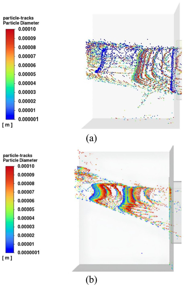
Particle dispersion (a) without a window screen, (b) with a Window Screen F.
Window screen efficiency
The effectiveness of the 6 different types of window screens on limiting the entry of particles into a childcare center was assessed and presented in Table 6. The pressure jump coefficient (C2) is a parameter that accounts for the depth of the porous medium to estimate the pressure drop across the porous jump zone, allowing for the determination of the pressure drop across the study area. The investigation revealed a significant range in window efficiency, influencing the potential particle entry into the childcare facility, with efficiencies ranging from 23.85% to 54.16%, respectively. Furthermore, the mass imbalances of the window screen simulations were recorded at less than 0.1% across the 6 window screen types. The study revealed that the smaller the pore size in the window screen the higher the efficiency in preventing outdoor atmospheric particles from entering indoors, with window screen A, featuring a 0.8 mm pore size and 0.5 mm thickness, emerging as the most efficient at 54.16% with the highest pressure drop. It has been reported that there is a relationship between pressure drop and particle removal. 71 When there is a higher pressure drop in a filtration system, it becomes more difficult for air to move through the filter. Consequently, this resistance prevents airborne particles from entering easily, acting as a protective measure to prevent the infiltration of contaminants. Conversely, the Window Screen F with the largest pore size (2 mm) and thickness (1 mm) displayed the lowest efficiency at 23.85%. The study also showed that screen thickness of 0.5 mm has higher efficiencies than screens with larger thickness of 1 mm. This might be due to the higher pressure across the window screen, indicating improved airflow dynamics and enhanced performance. This study aligns with previous findings that indicate higher capture efficiency in screens with lower thickness. 72 Additionally, it is important to note that the high filtration efficiency, despite the larger pore size compared to the particle diameters, can be attributed to various filtration mechanisms such as interception, diffusion, electrostatic attraction, inertial impaction, and Brownian motion. 73
Table 6.
Summary details of mass imbalance, pressure, velocity, and window screen efficiency in filtering outdoor particles from entering indoors.
| ID | C2 (m−1) | Massimbalance(%) | Pressure (Pa) | Velocity (m/s) | η (%) | ||
|---|---|---|---|---|---|---|---|
| Inlet | Outlet | Inlet | Outlet | ||||
| A | 177733.067 | 0.05 | 21.137 | 0.009 | 0.117 | 1.486 | 54.16 |
| B | 88866.53348 | 0.06 | 19.680 | 0.042 | 0.755 | 1.358 | 51.17 |
| C | 55314.70209 | 0.07 | 18.431 | 0.189 | 1.423 | 1.502 | 52.22 |
| D | 27657.35104 | 0.06 | 18.016 | 0.221 | 1.388 | 1.466 | 41.38 |
| E | 8797.409893 | 0.05 | 18.789 | 0.188 | 1.324 | 1.361 | 45.97 |
| F | 4398.704947 | 0.06 | 13.380 | 0.209 | 1.850 | 2.693 | 23.85 |
C2 = pressure jump coef.
Conclusion
Indoor air quality holds significant importance, particularly as people spend more time indoors, and it relies heavily on building attributes, such as ventilation. Natural ventilation can inadvertently introduce contaminants from outdoors to indoors, potentially causing adverse health effects on individuals. In this study, a numerical analysis was conducted to explore the impact of outdoor air on indoor air quality within a childcare center located near a small-scale industrial area. The findings revealed that the presence of a window screen provides notable advantages in controlling particle infiltration when compared to scenarios without a screen. Specifically, larger particles tend to pass directly through the window within the height of the breathing zone. On the other hand, even with a screen featuring larger pores, there is a discernible shift in dispersion patterns, indicating a reduction in particle penetration through the window. In a comparative study of window screens with diameters ranging from 0.8 mm to 2 mm and varying thickness, this research examined pressure and velocity distributions, revealing distinctions in maximum velocities and pressures. The introduction of window screens resulted in a notable reduction in velocity, with the smallest screen size (R0.8T2) exhibiting the highest velocities. Pressure variations were associated with screen size effects. Nevertheless, introducing a smaller window screen in the childcare center led to a significant increase in pressure drop compared to configurations without any window screen and with a larger pore size window screen. Prioritizing particle reduction, it was found that the window screen, R0.8T2 with 0.5 mm thickness had the highest efficiency (54.16%) in particle removal, while the larger pore size (R2T3) with a larger thickness of 1 mm showed the lowest efficiency (23.85%). However, beyond pore size, the study emphasizes the critical role played by thickness in determining window screen efficiency. This study recommends considering window screens for particle reduction in the childcare center, for the protection of human health.
Footnotes
Funding: The author(s) disclosed receipt of the following financial support for the research, authorship, and/or publication of this article: This study was supported by Fundamental Fund (BRF2-NDFR29/2564) from Mahidol University and the On-site Laboratory Initiative from the Graduate School of Global Environmental Studies, Kyoto University, Japan and International Macquarie Research Excellence Scholarship (iMQRES), Macquarie University, Sydney, Australia.
The author(s) declare that they have no known competing financial interest or personal relationships that could have appeared to influence the work reported in this paper.
Author Contribution Statement: Cathleen Ariella Simatupang: Conceptualization, Methodology, Formal analysis, Investigation, Writing - Original Draft. Vladimir Strezov: Conceptualization, Writing – Review & Editing, Supervision. Suwanna Kitpati Boontanon: Conceptualization, Writing – Review & Editing, Funding acquisition, Visualization, Supervision. Prapat Pongkiatkul: Conceptualization, Methodology, Investigation, Formal analysis, Writing – Review & Editing. Narin Boontanon: Writing – Review & Editing, Visualization, Supervision. Ranjna Jindal: Writing – Review & Editing, Visualization, Supervision.
Ethics Approval and Consent to Participate: Not applicable.
Consent for Publication: All authors approved the manuscript for publication.
Availability of Data and Material: The authors confirm that the data supporting the findings of this study are available within the article. Data will be made available on request.
References
- 1. Tong STY, Lam KC. Are nursery schools and kindergartens safe for our kids? The Hong Kong study. Sci Total Environ. 1998;216:217-225. [DOI] [PubMed] [Google Scholar]
- 2. WHO. Ambient (outdoor) air pollution. 2022. Accessed September 19, 2023. https://www.who.int/news-room/fact-sheets/detail/ambient-(outdoor)-air-quality-and-health
- 3. Pope CA, Ezzati M, Dockery DW. Fine-particulate air pollution and life expectancy in the United States. N Engl J Med. 2009;360:376-386. [DOI] [PMC free article] [PubMed] [Google Scholar]
- 4. Anenberg SC, Horowitz LW, Tong DQ, West JJ. An estimate of the global burden of anthropogenic ozone and fine particulate matter on premature human mortality using atmospheric modeling. Environ Health Perspect. 2010;118:1189-1195. [DOI] [PMC free article] [PubMed] [Google Scholar]
- 5. Dimitroulopoulou S, Dudzińska MR, Gunnarsen L, et al. Indoor air quality guidelines from across the world: an appraisal considering energy saving, health, productivity, and comfort. Environ Int. 2023;178:108127. [DOI] [PubMed] [Google Scholar]
- 6. Pillarisetti A, Ye W, Chowdhury S. Indoor air pollution and health: bridging perspectives from developing and developed countries. Annu Rev Environ Resour. 2022;47:197-229. [Google Scholar]
- 7. Nazaroff WW, Goldstein AH. Indoor chemistry: research opportunities and challenges. Indoor Air. 2015;25:357-361. [DOI] [PubMed] [Google Scholar]
- 8. Farrow A, Taylor H, Golding J. Time spent in the home by different family members. Environ Technol (United Kingdom). 1997;18:605-613. [Google Scholar]
- 9. Bateson TF, Schwartz J. Children’s response to air pollutants. J Toxicol Environ Heal - Part A Curr Issues. 2008;71:238-243. [DOI] [PubMed] [Google Scholar]
- 10. Branco PTBS, Alvim-Ferraz MCM, Martins FG, Sousa SIV. Indoor air quality in urban nurseries at Porto city: particulate matter assessment. Atmos Environ. 2014;84:133-143. [Google Scholar]
- 11. Yoon C, Lee K, Park D. Indoor air quality differences between urban and rural preschools in Korea. Environ Sci Pollut Res. 2011;18:333-345. [DOI] [PubMed] [Google Scholar]
- 12. Manisalidis I, Stavropoulou E, Stavropoulos A, Bezirtzoglou E. Environmental and health impacts of air pollution: a review. Front Public Heal. 2020;8:1-13. [DOI] [PMC free article] [PubMed] [Google Scholar]
- 13. Chen T, Liu X, Li X, et al. Heavy metal sources identification and sampling uncertainty analysis in a field-scale vegetable soil of Hangzhou, China. Environ Pollut. 2009;157:1003-1010. [DOI] [PubMed] [Google Scholar]
- 14. Pallarés S, Gómez ET, Martínez A, Jordán MM. The relationship between indoor and outdoor levels of PM10 and its chemical composition at schools in a coastal region in Spain. Heliyon. 2019;5:e02270. [DOI] [PMC free article] [PubMed] [Google Scholar]
- 15. Majd E, McCormack M, Davis M, et al. Indoor air quality in inner-city schools and its associations with building characteristics and environmental factors. Environ Res. 2019;170:83-91. [DOI] [PMC free article] [PubMed] [Google Scholar]
- 16. Swamy GSNVKSN. Development of an indoor air purification system to improve ventilation and air quality. Heliyon. 2021;7:e08153. [DOI] [PMC free article] [PubMed] [Google Scholar]
- 17. Peng Y, Lei Y, Tekler ZD, Antanuri N, Lau SK, Chong A. Hybrid system controls of natural ventilation and HVAC in mixed-mode buildings: a comprehensive review. Energy Build. 2022;276:112509. [Google Scholar]
- 18. Chilton A, Novo P, Mcbride N, Lewis-Nunes A, Johnston I, Rene J. Natural ventilation and acoustic comfort to cite this version. Proceedings of the Acoustics. 23-27 April 2012, Nantes, France. 2012:8. Accessed August 18, 2021. https://hal.archives-ouvertes.fr/hal-00810623 [Google Scholar]
- 19. Liu C, Hsu PC, Lee HW, et al. Transparent air filter for high-efficiency PM 2.5 capture. Nat Commun. 2015;6:6205. [DOI] [PubMed] [Google Scholar]
- 20. Huang WR, He Z, Wang JL, Liu JW, Yu SH. Mass production of nanowire-nylon flexible transparent smart windows for PM2.5 capture. iScience. 2019;12:333-341. [DOI] [PMC free article] [PubMed] [Google Scholar]
- 21. Zhao X, Wang S, Yin X, Yu J, Ding B. Slip-effect functional air filter for efficient purification of PM 2.5. Sci Rep. 2016;6:1-11. [DOI] [PMC free article] [PubMed] [Google Scholar]
- 22. Khalid B, Bai X, Wei H, Huang Y, Wu H, Cui Y. Direct blow-spinning of nanofibers on a window screen for highly efficient PM2.5 removal. Nano Lett. 2017;17:1140-1148. [DOI] [PubMed] [Google Scholar]
- 23. USEPA. What is a HEPA Filter? 2023. Accessed September 19, 2023. https://www.epa.gov/indoor-air-quality-iaq/what-hepa-filter
- 24. Bian Y, Wang S, Zhang L, Chen C. Influence of fiber diameter, filter thickness, and packing density on PM2.5 removal efficiency of electrospun nanofiber air filters for indoor applications. Build Environ. 2020;170:106628. [Google Scholar]
- 25. Xia T, Bian Y, Shi S, Zhang L, Chen C. Influence of nanofiber window screens on indoor PM2.5 of outdoor origin and ventilation rate: an experimental and modeling study. Build Simul. 2020;13:873-886. [Google Scholar]
- 26. Shi S, Bian Y, Zhang L, Chen C. A method for assessing the performance of nanofiber films coated on window screens in reducing residential exposures to PM2.5 of outdoor origin in Beijing. Indoor Air. 2017;27:1190-1200. [DOI] [PubMed] [Google Scholar]
- 27. Choi YH, Lee J, Khang DY. A reusable, isoporous through-hole membrane filter for airborne particulate matter removal. J Memb Sci. 2020;612:118474. [Google Scholar]
- 28. Zhang X, Zhang W, Yi M, et al. High-performance inertial impaction filters for particulate matter removal. Sci Rep. 2018;8:4757. [DOI] [PMC free article] [PubMed] [Google Scholar]
- 29. Wang C-S, Otani Y. Removal of nanoparticles from gas streams by fibrous filters: a review. Ind Eng Chem Res. 2013;52:5-17. [Google Scholar]
- 30. Lateb M, Meroney RN, Yataghene M, Fellouah H, Saleh F, Boufadel MC. On the use of numerical modelling for near-field pollutant dispersion in urban environments - a review. Environ Pollut. 2016;208:271-283. [DOI] [PubMed] [Google Scholar]
- 31. Norton T, Sun DW, Grant J, Fallon R, Dodd V. Applications of computational fluid dynamics (CFD) in the modelling and design of ventilation systems in the agricultural industry: a review. Bioresour Technol. 2007;98:2386-2414. [DOI] [PubMed] [Google Scholar]
- 32. Sharma C, Malhotra D, Rathore AS. Review of computational fluid dynamics applications in biotechnology processes. Biotechnol Prog. 2011;27:1497-1510. [DOI] [PubMed] [Google Scholar]
- 33. Xia B, Sun DW. Applications of computational fluid dynamics (CFD) in the food industry: a review. Comput Electron Agric. 2002;34:5-24. [Google Scholar]
- 34. Chen Q, Srebric J. Application of CFD tools for indoor and outdoor environment design. Int J Archit Sci. 2000;1:14-29. [Google Scholar]
- 35. Lee IB, Bitog JPP, Hong SW, et al. The past, present and future of CFD for agro-environmental applications. Comput Electron Agric. 2013;93:168-183. [Google Scholar]
- 36. Tsou JY. Strategy on applying computational fluid dynamic for building performance evaluation. Autom Constr. 2001;10:327-335. [Google Scholar]
- 37. Chu CR, Yang KJ. Transport process of outdoor particulate matter into naturally ventilated buildings. Build Environ. 2022;207:108424. [Google Scholar]
- 38. Chu CR, Lan TW, Tasi RK, Wu TR, Yang CK. Wind-driven natural ventilation of greenhouses with vegetation. Biosyst Eng. 2017;164:221-234. [Google Scholar]
- 39. Panjwani B, Olsen JE. Design and modelling of dust capturing system in thermally stratified flowing conditions. Build Environ. 2020;171:106607. [Google Scholar]
- 40. Xu G, Wang J. CFD modeling of particle dispersion and deposition coupled with particle dynamical models in a ventilated room. Atmos Environ. 2017;166:300-314. [Google Scholar]
- 41. KMUTT. Weather station. 2022. Accessed October 3, 2023. http://emtrontech.com/KMUTT_MET/dashboard.html?v7&id=2
- 42. TMD. Meteorological department | weather forecast for February 2023. 2022. Accessed August 4, 2023. https://www.tmd.go.th/forecast/monthly/022023
- 43. Marco Specialty Steel. Perforated metal open area calculations - marco specialty steel. 2023. Accessed October 30, 2023. https://www.marcospecialtysteel.com/perforated-metal-open-area-calculations/
- 44. Wang L, Zhang L, Lian G. A CFD simulation of 3D air flow and temperature variation in refrigeration cabinet. Procedia Eng. 2015;102:1599-1611. [Google Scholar]
- 45. Gousseau P, Blocken B, Stathopoulos T, van Heijst GJF. CFD simulation of near-field pollutant dispersion on a high-resolution grid: a case study by LES and RANS for a building group in downtown Montreal. Atmos Environ. 2011;45:428-438. [Google Scholar]
- 46. Alvear Pérez LC, Anaya Acosta MJ, Pedraza Yepes CA. CFD simulation data of a pico-hydro turbine. Data Br. 2020;33:106596. [DOI] [PMC free article] [PubMed] [Google Scholar]
- 47. Chen Q, Srebric J. A procedure for verification, validation, and reporting of indoor environment CFD analyses. HVAC R Res. 2002;8:201-216. [Google Scholar]
- 48. Choi J, Hong J, Hong T. Analysis of the effect of dust barriers on particulate matter dispersion from a construction site using CFD simulation. Environ Pollut. 2023;338:122679. [DOI] [PubMed] [Google Scholar]
- 49. Li Q, Wu B, Liu J, Zhang H, Cai X, Song Y. Characteristics of the atmospheric boundary layer and its relation with PM2.5 during haze episodes in winter in the North China Plain. Atmos Environ. 2020;223:117265. [Google Scholar]
- 50. Xie W, Fan Y, Zhang X, Tian G, Si P. A mathematical model for predicting indoor PM2.5 concentration under different ventilation methods in residential buildings. Build Serv Eng Res Technol. 2020;41:694-708. [Google Scholar]
- 51. Geng F, Luo G, Wang Y, et al. Dust dispersion in a coal roadway driven by a hybrid ventilation system: a numerical study. Process Saf Environ Prot. 2018;113:388-400. [Google Scholar]
- 52. Feng X, Geng F, Teng H, et al. Field measurement and numerical simulation of dust migration in a high-rise building of the mine hoisting system. Environ Sci Pollut Res. 2022;29:38038-38053. [DOI] [PubMed] [Google Scholar]
- 53. Tancharoen A, Ponpesh P. Investigation of PM2.5 dispersion in Din Daeng District, Bangkok, using computational fluid dynamics modeling. Eng J. 2023;27:1-9. [Google Scholar]
- 54. Xu G, Chang P, Mullins B, Zhou F, Hu S. Numerical study of diesel particulate matter distribution in an underground mine isolated zone. Powder Technol. 2018;339:947-957. [Google Scholar]
- 55. Gui C, Geng F, Tang J, et al. Gas–solid two-phase flow in an underground mine with an optimized air-curtain system: a numerical study. Process Saf Environ Prot. 2020;140:137-150. [Google Scholar]
- 56. Danilishin AM, Kozhukhov YV, Yun VK. Multi-objective optimization for impeller shroud contour, the width of vane diffuser and the number of blades of the centrifugal compressor stage based on the CFD calculation. IOP Conf Ser Mater Sci Eng. 2015;90:012046. [Google Scholar]
- 57. Rane S, He L. CFD analysis of flashing flow in two-phase geothermal turbine design. J Comput Des Eng. 2020;7:238-250. [Google Scholar]
- 58. Chougule AB, Cam MTCAD. Pusher Configured Turboprop Engine Oil Cooler Ejector Performance: CFD Analysis And Validation. 2017. Proceedings of the 6th International and 43rd National Conference on Fluid Mechanics and Fluid Power. December 15-17, 2016, MNNITA, Allahabad, U.P., India. [Google Scholar]
- 59. Vosoughifar HR, Dolatshah A, Shokouhi SKS, Nezhad SRH. Evaluation of fluid flow over stepped spillways using the finite volume method as a novel approach. Stroj Vestnik/J Mech Eng. 2013;59:301-310. [Google Scholar]
- 60. Kuron M. 3 Criteria for assessing CFD convergence. EngineeringCom; 2015. Accessed October 9, 2023. https://www.engineering.com/story/3-criteria-for-assessing-cfd-convergence [Google Scholar]
- 61. Xiong J, Shao W, Wang L, et al. High-performance anti-haze window screen based on multiscale structured polyvinylidene fluoride nanofibers. J Colloid Interface Sci. 2022;607:711-719. [DOI] [PubMed] [Google Scholar]
- 62. Shajahan A, Culp CH, Williamson B. Effects of indoor environmental parameters related to building heating, ventilation, and air conditioning systems on patients’ medical outcomes: a review of scientific research on hospital buildings. Indoor Air. 2019;29:161-176. [DOI] [PMC free article] [PubMed] [Google Scholar]
- 63. Demirel Y. 5.2 energy conservation. In Comprehensive Energy Systems (Vols. 5–5). https://doi.org/10.1016/B978-0-12-809597-3.00505-8 [Google Scholar]
- 64. Leivo V, Kiviste M, Aaltonen A, Turunen M, Haverinen-Shaughnessy U. Air pressure difference between indoor and outdoor or staircase in multi-family buildings with exhaust ventilation system in Finland. Energy Procedia. 2015;78:1218-1223. [Google Scholar]
- 65. Choi DH, Kang DH. Indoor/Outdoor relationships of airborne particles under controlled pressure difference across the building envelope in Korean multifamily apartments. Sustain. 2018;10:4074. [Google Scholar]
- 66. Wu B, Men J, Chen J. Numerical study on particle removal performance of pickup head for a street vacuum sweeper. Powder Technol. 2010;200:16-24. [Google Scholar]
- 67. Heiselberg P, Svidt K, Nielsen PV. Characteristics of airflow from open windows. Build Environ. 2001;36:859-869. [Google Scholar]
- 68. Bassiouny MK, Martin H. Flow distribution and pressure drop in plate heat exchangers-I U-type arrangement. Chem Eng Sci. 1984;39:693-700. [Google Scholar]
- 69. Ma Y, Jiang Y, Li L. Numerical simulation of PM2.5 distribution in indoor air. Procedia Eng. 2015;121:1939-1947. [Google Scholar]
- 70. Orza JAG, Cabello M, Lidón V, Martínez J. Contribution of resuspension to particulate matter inmission levels in SE Spain. J Arid Environ. 2011;75:545-554. [Google Scholar]
- 71. Teng G, Shi G, Zhu J, Qi J. A numerical simulation method for pressure drop and normal air velocity of pleated filters during dust loading. PLoS One. 2023;18:e0282026. [DOI] [PMC free article] [PubMed] [Google Scholar]
- 72. Sabirova A, Wang S, Falca G, Hong PY, Nunes SP. Flexible isoporous air filters for high-efficiency particle capture. Polymer (Guildf). 2021;213:123278. [Google Scholar]
- 73. Han S, Kim J, Ko SH. Advances in air filtration technologies: structure-based and interaction-based approaches. Mater Today Adv. 2021;9:100134. [Google Scholar]


