Abstract
Sodium-ion batteries (SIBs) is a promising technology for next-generation energy storage. However, their performance is limited at low temperatures due to the inferior bulk and interfacial resistance of current electrolytes. Here we present a systematic study to evaluate carboxylate ester-based electrolytes for SIB applications, due to their favorable properties (i.e., low melting point, low viscosity and high dielectric constant). The effects of salt, concentration and solvent molecular structure were systematically examined and compared with those of carbonate-based electrolytes. By combining electrochemical tests with spectroscopic characterization, the performance of selective carboxylate ester-based electrolytes in hard carbon/Na and Na3V2(PO4)3/Na half-cells was evaluated. We found carboxylates enable high electrolyte conductivities, especially at low temperatures. However, carboxylates alone are inadequate to form a stable interphase due to their high reactivity, which can be addressed by choosing a suitable anion and facilitating anion-rich Na+ solvation by increasing salt concentration. Fundamental knowledge on the chemistry–property–performance correlation of this new family of electrolytes was obtained, and their benefits and pitfalls were thoroughly discussed. These discoveries and knowledge will shed light on the potential of carboxylate ester-based electrolytes and provide the foundation for further electrolyte engineering.
Carboxylate is promising solvent type for low-temperature sodium-ion batteries.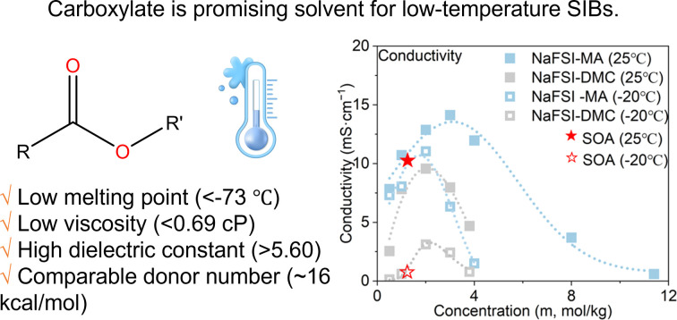
Introduction
The progressive greenhouse effect is having a discernible impact on the earth's climate, giving rise to increasingly extreme weather patterns. A significant contributor to this problem is CO2 emissions. Among various economic sectors, transportation and electricity generation are the two primary sources of CO2 emissions. To decarbonize these sectors, we must phase out the internal combustion engine in favor of electric vehicles and scale up renewable electricity generation from solar and wind. Both require high-performance and cost-effective energy storage technology. Rechargeable batteries are a promising solution for this need, but the mainstream Li-ion batteries (LIBs) are expensive (the current price is $151 per kW h)1 due to the usage of costly metals such as Li, Co and Ni.2–4 Due to their potentially lower cost and better sustainability, Na-ion batteries (SIBs) are attracting increasing attention as an alternative to LIBs.
The development of SIBs faces several challenges.5 First, most anode materials have a low initial coulombic efficiency (ICE) of 30–70%.6 Such low ICE means that a large portion of Na+ extracted from the cathode during the first charge is consumed by side reactions, which significantly compromises the energy density and cycling stability. Second, their rate capability and cycling stability are inferior to those of LIBs. The sluggish diffusion of the large Na+ leads to a poor rate capability. The huge volume changes upon Na insertion and the unsatisfactory surface passivation at the anode/cathode surface compromise cycling stability.7,8 Thirdly, they have poor low-temperature performance. Researchers have explored various types of solvent to compose SIB electrolytes (Table S1†), including carbonate, ether, phosphate, etc. Among them, the state-of-the-art (SOA) SIB electrolyte, typically made of 1 M NaClO4 or NaPF6 dissolved into a blend of cyclic carbonate and linear carbonate (Table S2†), generally has the highest conductivity, and has potential application at low temperatures. However, such carbonate-type SOA has a minimum operating temperature of ca. −20 °C. This cannot satisfy the needs for stationary energy storage applications, especially for regions at high altitudes and/or latitudes where outdoor temperatures can fall below −20 °C or even −30 °C during the winter. At such low temperatures, SIB electrolytes can crystallize or even freeze, thus causing battery failure.9 Despite a lot of work having been done to address the first two challenges, less attention has been given to resolving the low-temperature shortcomings.
Among various battery design factors, electrolytes play a pivotal role in governing low-temperature performance for three reasons: (1) they determine the concentration of free ions and their mobility, thereby regulating electrolyte conductivity; (2) their decomposition dictates the composition of the cathode/solid electrolyte interphase (CEI/SEI), thereby regulating the interphase resistance; (3) they determine the solvent–cation interaction, thereby regulating the de-solvation energy during the interfacial charge transfer reaction.
The poor low-temperature performance of current SIB electrolytes can be attributed to their inferior bulk and interfacial properties. The main solvent, EC, has a high melting point (37 °C) and it becomes very viscous or even solidifies at low temperatures, which significantly reduces electrolyte conductivity and increases interfacial resistance. For example, at −20 °C, the conductivity of 1.0 M NaPF6-EC/EMC (EC: ethylene carbonate; EMC: ethyl methyl carbonate) reduces to 1.4 mS cm−1, and the charge transfer resistance increases by two orders of magnitude from 322 Ω to ∼31 000 Ω.10 Such a dramatic loss of performance can be seen in other SIB electrolytes, as summarized in Table S3.†
To address this challenge, many strategies have been explored. Adding a co-solvent with a low melting point and low viscosity can prevent electrolytes from freezing and increase their conductivity at low temperatures. For example, adding 25% methyl acetate (MA) into 1 M LiPF6-EC/DEC/DMC (1 : 1 : 1) (DEC: diethyl carbonate; DMC: dimethyl carbonate) can increase its conductivity at −60 °C by one order of magnitude from <0.1 mS cm−1 to ∼1 mS cm−1.11 This design is effective, but it compromises the compatibility of electrolytes with electrodes at high operating temperatures (such as 45 °C).12,13 Another approach involves suppressing the solvent–cation interaction by using weakly polar solvents14–16 to decrease charge transfer resistance. For example, the Li+–solvent binding energy can be reduced by ∼25% when the polarity of ethyl acetate is weakened by grafting two F atoms to the acetyl group.16 However, this strategy leads to poor salt dissociation17 and low conductivity due to the reduced solvent polarity.
From the perspective of solvent selection, the ideal solvent for low-temperature electrolytes should have: (1) a low melting point so it does not freeze at low temperatures; (2) a high dielectric constant and a low viscosity to ensure good conductivity; (3) a low donor number (DN) that leads to weak solvent–cation binding and fast charge transfer kinetics. Among various solvent families, linear carboxylate esters are a promising one that satisfies all the above requirements with low melting points (below −70 °C), low viscosities (<0.6 cP), high dielectric constants (above 5.6) and low DNs (∼16 kcal mol−1) (Table S4†). Motivated by these benefits, carboxylate esters have been widely used as co-solvents in electrolyte formulation to enhance LIBs' low-temperature performance. For example, adding 20% carboxylate ester into 1 M LiPF6-EC/EMC can significantly enhance the low-temperature performance of LIBs.12 In a few studies, they are explored as the main solvent.18 For example, Dahn et al.19 studied MA based electrolytes and found that they can double the electrolyte conductivity and reduce the Li+ de-solvation energy compared to carbonate ester-based electrolytes. Consequently, this carboxylate ester-based electrolyte increases the capacity of LIBs by three times at low temperatures.
Despite their promising potential, carboxylate esters are seldom used in the formulation of SIB electrolytes. To the best of our knowledge, only one study13 investigated a carboxylate ester as the co-solvent (20%), and there are no studies exploring carboxylate esters as the main solvent (≥90%). Previous studies on LIBs found that carboxylate esters generally cannot form a stable SEI because of their high reactivity.19–24 For this reason, they were always used as the co-solvents (less than 60%).12,19,21,25 However, the salt effect was seldom taken into consideration when evaluating carboxylates during electrolyte engineering. Many recent studies have revealed that by tuning the solvation shell structure, it is possible to enable anions to participate in SEI formation.26–28 This opens the possibility of curbing the reactivity of carboxylate esters by forming anion-derived SEIs and utilizing them as the main solvent for low-temperature electrolyte design.
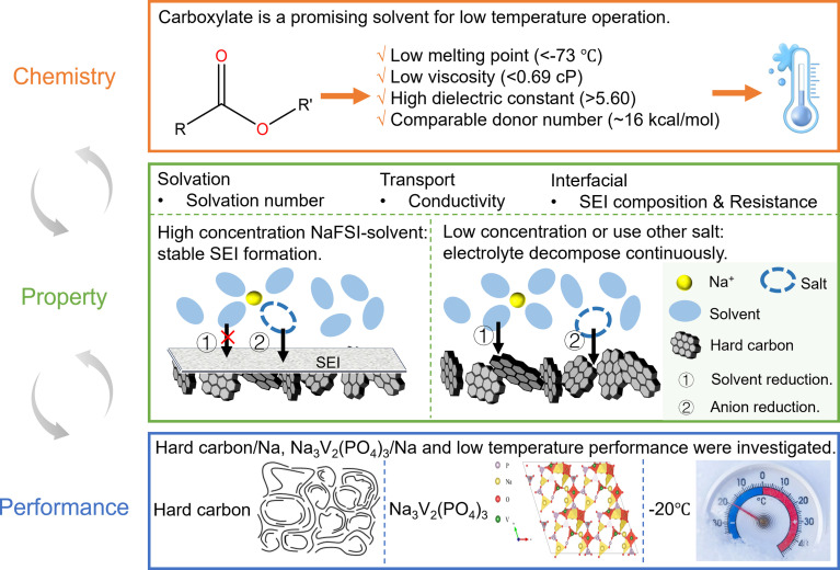
In this work, we aim to comprehensively explore linear carboxylate esters (Table 1) as the main solvent for SIB electrolyte design and assess their potential in enhancing the low-temperature performance (Fig. 1). A systematic study that includes salt screening, concentration optimization and comparison with carbonates was performed to examine the multiple design freedoms of carboxylate ester-based electrolytes. By combining electrochemical tests with spectroscopic characterization, we evaluated the performance of selective carboxylate ester-based electrolytes in hard carbon (HC)/Na and Na3V2(PO4)3 (NVP)/Na half-cells and correlated their performance with their structure and properties (both transport and interfacial). Fundamental knowledge of the chemistry–property–performance correlation of this new family of electrolytes was obtained, and their benefits and pitfalls were thoroughly discussed. These discoveries and knowledge will shed light on the potential of carboxylate ester-based electrolytes and provide the foundation for further electrolyte engineering.
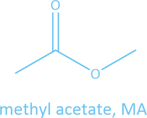
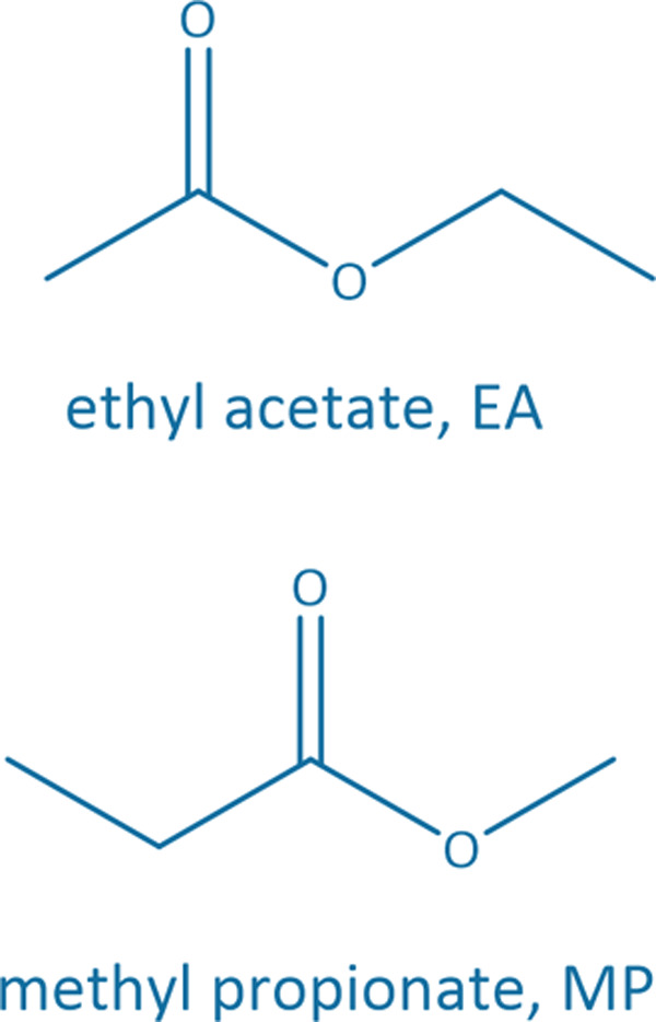
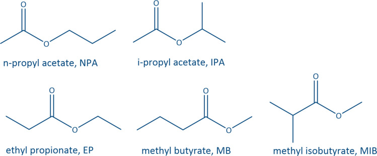
Common linear carboxylate ester and carbonate ester molecules.
| 3-Carbon | 4-Carbon | 5-Carbon | |
|---|---|---|---|
| Carboxylates |
|
|
|
| Carbonates |
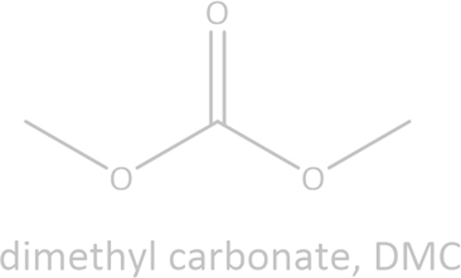
|
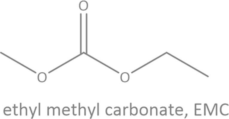
|
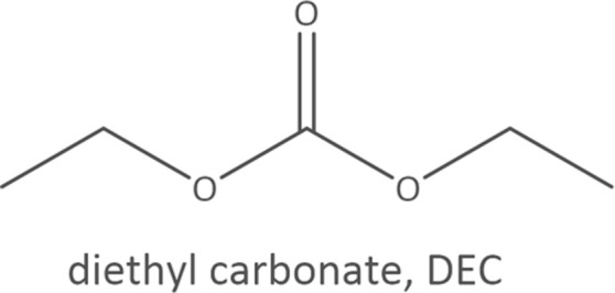
|
Fig. 1. Scope of this work. The structures of hard carbon29 and Na3V2(PO4)3 30 are cited from the literature.
Results
Physical properties
Common linear carboxylate ester (abbreviated as carboxylate hereafter) molecules are given in Table 1 and compared with carbonate esters (abbreviated as carbonate hereafter). Structurally, a carboxylate (formula: RC( O)OR′, where R and R′ are alkyl groups) contains a carbonyl group in which the C atom is singly bonded to a second oxygen atom, while a carbonate (formula: ROC( O)OR′) consists of a carbonyl group flanked by two alkoxy groups. Specifically, methyl acetate (MA), ethyl acetate (EA) and n-propyl acetate (NPA) have the same CH3C( O)OR1 structure with different R1 groups. Methyl propionate (MP) and ethyl propionate (EP) have the same CH3CH2C( O)OR2 structure with different R2 groups. EA and MP are isomers, and NPA, isopropyl acetate (IPA), EP, methyl butyrate (MB) and methyl isobutyrate (MIB) are isomers.
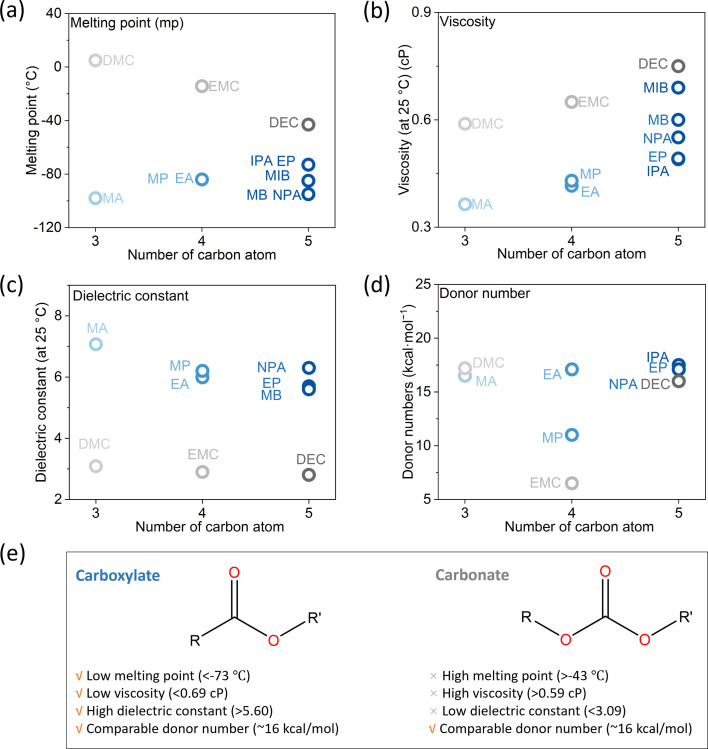
Among different properties, the melting point, the dielectric constant and viscosity, and the donor number (DN) respectively determine the liquid range, the conductivity, and the de-solvation energy of the electrolyte, thereby influencing the low-temperature performance. These properties are plotted against the number of carbon atoms in the molecules in Fig. 2, S1 and Table S4,† and compared with the corresponding carbonate. Generally, all carboxylates have melting points below −70 °C, lower than those of carbonates and far below those of SOA electrolytes (−30 °C).9 Their viscosities are in the range of 0.36–0.69 cP, lower than those of carbonates. Due to the asymmetry of the molecular structure, they are much more polar than carbonates, with dielectric constants above 5.6. Their donor numbers, around 16 kcal mol−1, are comparable to those of carbonates except for EMC and MP. As the chain length increases, the melting point and viscosity increase due to the larger intermolecular interaction, while the dielectric constant decreases due to the larger molecular size and, consequently, higher molecular polarizabilities. Overall, compared with carbonates, carboxylates have lower melting points and viscosities, higher dielectric constants, and comparable donor numbers. These features make them ideal candidates for making low-temperature electrolytes. Among all carboxylates, MA stands out because it has the lowest melting point, the lowest viscosity, and the highest dielectric constant. Therefore, in the below discussion, we choose MA as the representative carboxylate for a systematic study. A carbonate with the same chain length as MA, i.e., DMC, is used for comparison whenever possible.
Fig. 2. Physical properties. (a) Melting point, (b) viscosity, (c) dielectric constant and (d) donor number. The dielectric constant of MIB and IPA, as well as the donor number of MB and MIB, are not available in the literature. (e) The benefits of carboxylates compared to carbonates.
Salt effect
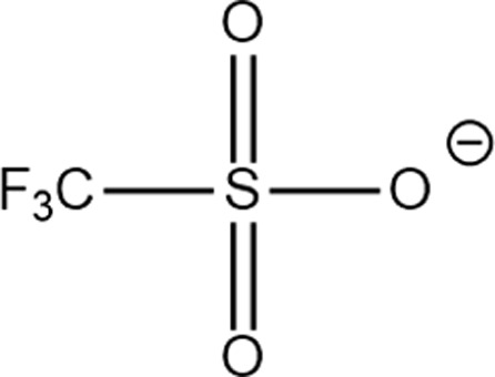
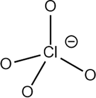
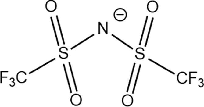
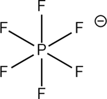
Previous studies on linear carboxylate-based electrolytes are limited to NaPF6 salt,13,22 whereas other salts have never been studied. Here, a systematic screening was performed to identify the best salt(s) for making carboxylate-based electrolytes. Six commercially available Na salts (Table 2) were compared in terms of solubility and conductivity. In addition, their compatibility with the SOA SIB anode material, hard carbon (HC), was also compared.
Structure of different Na salts and their room-temperature solubility in MA.
| Salt | NaBF4 | NaOTf | NaClO4 | NaTFSI | NaPF6 | NaFSI | |
|---|---|---|---|---|---|---|---|
| Chemical structure of the anion |
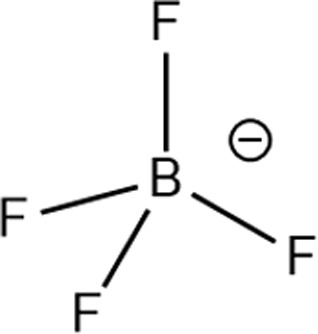
|
|
|
|
|
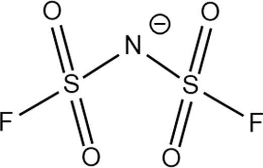
|
|
| Solubility in MA | Molality (m, mol kg−1) | <0.01 | 0.1–0.2 | 1.6–1.8 | 5.2–6.0 | 6.0–7.0 | 11.0–11.8 |
| Molarity (M, mol L−1) | <0.01 | 0.1–0.2 | 1.5–1.7 | 4.8–5.6 | 5.6–6.5 | 10.3–11.0 | |
The room-temperature solubility of these Na salts follows the order of NaBF4 ≪ NaOTf ≪ NaClO4 < NaTFSI < NaPF6 < NaFSI (Table 2). The salt solubility depends on a comparison of the lattice energy and the solvation energy. The former depends on the sum of the anion and cation radii, whereas the latter has separate anion and cation terms. Since the solvation of smaller ions (Na+ here) dominates the salt solvation energy, the difference in salt solubility here is mainly related to their lattice energy: salts with higher lattice energy have lower solubility.31 Owing to their extremely low solubilities, NaBF4 and NaOTf were excluded from further study. At a salt concentration of 1 m, the conductivity of MA electrolytes made with different Na salts follows the order of NaClO4 < NaTFSI < NaPF6 < NaFSI (Fig. 3a). For all salts, the conductivity shows a non-monotonic dependence on salt concentration and peaks at an intermediate concentration of 1–3 m due to the competing effect of charge carrier concentration and viscosity. NaFSI enables the highest conductivity among different salts, showing a maximum conductivity of 14.1 mS cm−1 at a concentration of 3 m.
Fig. 3. Salt effect. (a) The conductivity of MA-based electrolytes with different Na salts and (b and c) CV curves of the HC/Na cell using 1 m and 4 m MA-based electrolytes with different Na salts.
The compatibility of different salts with HC was examined by conducting cyclic voltammetry (CV) in HC/Na cells (Fig. 3b and c). During the cathodic scan, both Na+ intercalation into HC and electrolyte decomposition can happen. If there is a reversible reaction, an anodic peak is expected during the subsequent anodic scan. For NaFSI-MA electrolyte, there are both reduction and oxidation peaks at a normal salt concentration (1 m) and a high concentration (4 m). In contrast, no oxidation peaks are observed for NaClO4-MA, NaTFSI-MA and NaPF6-MA at either 1 m or 4 m, suggesting the reduction reaction in these electrolytes is likely only irreversible electrolyte decomposition. This difference can be explained by the well-known nature of FSI− to form a stable anion-dominated SEI upon reduction9 that can prevent continuous electrolyte decomposition.
Summarizing the salt effect study, NaFSI stands out among all six sodium salts due to its highest solubility, highest conductivity, and compatibility with HC. Therefore, NaFSI was selected as the salt for further study as discussed below.
Salt concentration effect
Salt concentration plays an important role in determining the bulk and interfacial properties of electrolytes by regulating the cation solvation shell, as evidenced by recent studies on high concentration electrolytes32,33 and ultralow concentration electrolytes.34 Here, we study how the salt concentration of the NaFSI-MA electrolyte affects the performance of HC/Na half cells. Specifically, the capacity, CE and cycling stability were characterized and correlated with interfacial properties and electrolyte structures.
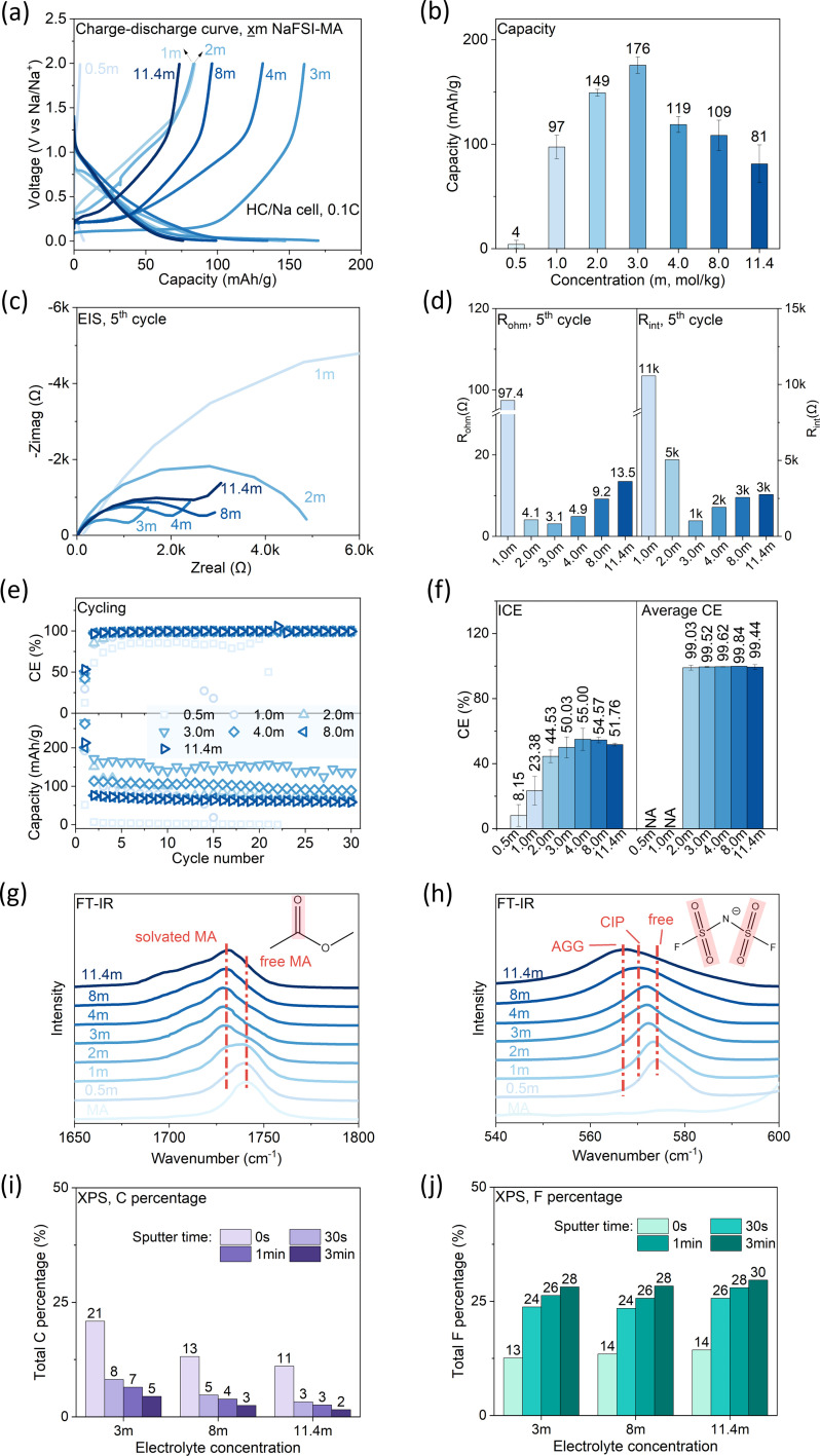
The charge–discharge profiles of the HC/Na half cells (Fig. 4a) show a typical slope–plateau curve, where the slope corresponds to Na+ insertion into parallel graphene layers of HC, while the plateau corresponds to Na+ insertion into HC nanopores.35–37 The capacity is non-monotonically dependent on salt concentration (Fig. 4b), and a maximum capacity of 176 mA h g−1 is observed at a concentration of 3 m. The electrochemical impedance spectra (EIS) were collected (Fig. 4c), and the ohmic resistance (Rohm) (Fig. 4d, left) and interfacial resistance (Rint) (Fig. 4d, right) were obtained by fitting EIS with an equivalent circuit (Fig. S2†). Here the interfacial resistance includes both the charge transfer resistance (Rct) and the SEI resistance (RSEI), but they cannot be deconvoluted from only one semi-circle in the EIS. Both Rohm and Rint show a non-monotonic dependence on salt concentration and reach the minimum at 3 m, consistent with the capacity–concentration correlation. This suggests the capacity's dependence on concentration can be explained by the internal resistance, i.e., cells with higher internal resistance are more prone to reach cut-off voltage under constant-current operation, therefore delivering less capacity. Another key observation is that Rint is 2–3 orders higher than Rohm, indicating the internal resistance is dominated by interfacial resistance. The coulombic efficiency (CE) is compared in Fig. 4e and f. The ICE shows a non-monotonic dependence on salt concentration and 4 m electrolyte shows the maximum ICE (55.00%). After 30 cycles, high concentration electrolytes (≥3 m) all demonstrate average CE of >99.4%, suggesting the formation of a stable SEI. In contrast, low concentration electrolytes (≤1 m) cannot form a stable SEI as indicated by the fast capacity decay, the low ICE (<25%) and low average CE. Correspondingly, they show much higher interfacial resistance than other electrolytes.
Fig. 4. Concentration effect of NaFSI-MA electrolytes. Salt concentration in molality (x = 0.5, 1, 2, 3, 4, 8, 11.4). Discharge and charge rates: 0.1C. (a) Charging and discharging profiles of the 2nd cycle; (b) specific discharge capacity vs. concentration; (c) EIS after the 5th cycle; (d) Rohm and Rintvs. concentration; (e) CE (top) and capacity (bottom) vs. cycle number; (f) ICE (left) and average CE (21st–30th) (right) vs. concentration. (g and h) FT-IR profiles of NaFSI-MA with different salt concentrations; (i) C and (j) F atomic percentage of the SEI on the cycled HC anode surface characterized by XPS.
The CE's dependence on salt concentration can be explained by considering the solvation structure of Na+ ions in these electrolytes. The Na+ solvation structure was examined by Fourier-transform infrared spectroscopy (FT-IR). The peak at 1710–1770 cm−1 (Fig. 4g) is assigned to the C O stretching in MA,38 in which the feature at 1740 cm−1 corresponds to uncoordinated (free) MA. Its intensity decreases gradually, while another band attributed to solvated MA emerges at ∼1730 cm−1 and increases with salt concentration. This observation indicates that the fraction of free MA molecules decreases with salt concentration. The peak at ∼574 cm−1 (Fig. 4h) is assigned to the δaSO2 of FSI−,39 and is attributed to free FSI− and/or FSI− within a solvent-separated ion pair (SSIP) without direct coordination to Na+. As NaFSI concentration increases, this peak shifts from 574 to 567 cm−1, indicating the coordination of FSI− with Na+. When the FSI− anion coordinates with Na+, different local structures29 include contact ion pair (CIP) and aggregate (AGG) forms. The results show there are fewer free anions and more Na-anion coordination as salt concentration increases. Such coordination of FSI− with Na+ in a concentrated electrolyte lowers the lowest unoccupied molecular orbital (LUMO) level of FSI−, rendering it more prone to reduction compared to free FSI.40 Given the high reactivity of MA, free MA molecules are susceptible to reduction at the HC anode, but their decomposition does not form a stable SEI. The change of Na+ solvation structure in high-concentration electrolytes suppresses the reduction of MA while promoting the reduction of FSI−, thus allowing the formation of a stable SEI. This hypothesis is supported by X-ray photoelectron spectroscopy (XPS) results (Fig. 4i and j and S3†). In the SEI on cycled HC, the amount of organic components, an indicator of MA decomposition, decreases with salt concentration (Fig. 4i). In contrast, the amount of inorganic components, indicative of anion decomposition, increases with the salt concentration (Fig. 4j). In summary, increasing salt concentration leads to an anion-rich solvation shell, which favors anion decomposition that can form a stable SEI on the HC anode. In addition, 3 m NaFSI-MA electrolyte shows the highest capacity due to its lowest internal resistance.
Solvent effect: carboxylates vs. carbonates
To understand the uniqueness of carboxylate chemistry, we conducted a systematic comparison of carboxylates and carbonates. Of particular interest is how the minor difference in molecular structure between carboxylates and carbonates affects their physical properties and solvation structure, thus governing their electrochemical performance. As a representative linear carbonate, DMC is widely used as a co-solvent to reduce electrolyte melting point and viscosity. Structurally, it has a symmetric molecular structure compared to the asymmetric structure of MA, making it less polar but more resistant to reduction. Here, we first compared the conductivity, solvation structure and electrochemical performance of MA and DMC in both HC/Na and NVP/Na cells, and then examined the influence of chain length and molecule configuration.
Physical properties
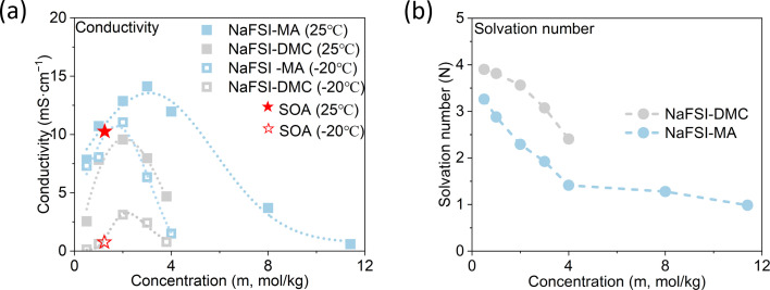
NaFSI-MA electrolytes show much higher conductivity than NaFSI-DMC electrolytes at both 25 °C and −20 °C (Fig. 5a), which can be attributed to MA's lower melting point, lower viscosity and higher dielectric constant. Specifically, 1 m NaFSI-MA shows a room temperature conductivity of 10.72 mS cm−1 and it decreases to 8.06 mS cm−1 at −20 °C, whereas 1 m NaFSI-DMC has a room temperature conductivity of 7.82 mS cm−1 and it decreases dramatically to 0.61 mS cm−1 at −20 °C. The FT-IR profiles (Fig. 4g and h and S4†) of both electrolytes were measured and the solvation number, i.e., the average number of solvent molecules coordinated to Na+, was calculated and compared in Fig. 5b (methods shown in the ESI†). At all measured concentrations, NaFSI-MA electrolytes have a lower solvation number than NaFSI-DMC electrolytes, similar to what was observed in the Li system.19 At 3 m, the solvation number of NaFSI-MA is 1.92, while that of NaFSI-DMC is 3.07. This result indicates there is less solvent and more anions in the Na+ solvation shell of NaFSI-MA compared to NaFSI-DMC.
Fig. 5. Solvent effect on bulk electrolyte. (a) Conductivity and (b) solvation number of NaFSI-DMC and NaFSI-MA electrolytes.
HC anode performance
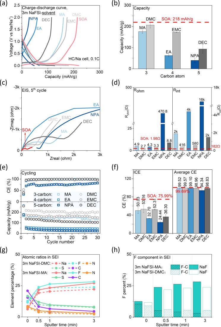
The cell with NaFSI-MA delivers less capacity than that with NaFSI-DMC (176 mA h g−1vs. 207 mA h g−1), and both show lower capacities than SOA electrolyte (218 mA h g−1) (1 M NaPF6-EC/DEC 1 : 1 by volume was chosen to represent SOA electrolyte) (Fig. 6a and b). This is consistent with the impedance study (Fig. 6c and d), which shows NaFSI-MA has higher ohmic (4.9 Ω vs. 2.7 Ω) and interfacial resistance (2000 Ω vs. 416 Ω) than its carbonate counterpart. Notably, the interfacial resistance of NaFSI-MA is almost 10 times higher than that of SOA electrolytes (182 Ω), suggesting the highly resistive SEI.41 Cells with NaFSI-MA and NaFSI-DMC show comparable ICE (50.03% vs. 53.16%) and average CE (99.52% vs. 99.57%) (Fig. 6e and f), both lower than those of SOA electrolyte (75.99% and 99.69%). EC, an indispensable component in SOA electrolyte, can form an alkyl carbonate (sodium double alkyl carbonate, NEDC)42 in the SEI. Such alkyl carbonate is believed to play a key role in forming a stable SEI in SOA electrolyte.43 The inferior CE of NaFSI-MA and NaFSI-DMC can be attributed to their solvent reactivity at low potential22,44 and inability to form a stable SEI. The lower ICE of NaFSI-MA than NaFSI-DMC can be explained by the different Na+ solvation structures. As previously discussed, the anion-rich solvation shell of NaFSI-MA leads to more anion decomposition, as confirmed by XPS (Fig. 6g and S5†). In general, the SEIs formed in the two electrolytes have similar organic and inorganic species. However, NaFSI-MA shows stronger peak density of Na 1s, S 2p, F 1s, N 1s and C 1s in SEI, indicating more electrolyte decomposition, consistent with its low CE and higher interfacial resistance. Moreover, the SEI in NaFSI-MA has more NaF (Fig. 6h), a decomposition product of FSI−, than its carbonate counterpart. These findings demonstrate that the anion-domain solvation shell in NaFSI-MA gives rise to an inorganic-rich SEI on the HC surface, and the low ICE and high interfacial resistance suggest stable SEI formation needs more electrolyte decomposition.
Fig. 6. Solvent effect on anode performance (solvent = carboxylate (MA, EA, NPA) or carbonate (DMC, EMC, DEC). Representative SOA electrolyte: 1 M NaPF6-EC/DEC 1 : 1 by volume). Discharge/charge rate: 0.1C. (a) Charging and discharging profiles of the 2nd cycle; (b) specific discharge capacity; (c) EIS curve of each cell after the 5th cycle; (d) Rohm and Rint after the 5th cycle; (e) CE (top) and capacity (bottom) with cycling; (f) ICE and average CE (21st–30th); (g and h) SEI component analyzed by XPS.
Molecule structure effect
Building on the understanding of MA and DMC, next we studied how the chain length and structure of the carboxylate affect their electrochemical performance. For both the carboxylate and carbonate, cell capacity decreases as the solvent chain length increases, and cells with carboxylate show less capacity than their carbonate counterparts (Fig. 6a and b) due to their larger internal resistance (Fig. 6c and d). Additionally, the internal resistance is dominated by the interfacial resistance, which increases with solvent chain length probably due to the decreasing cathodic stability.11 Of particular interest is that the interfacial resistances of the carboxylate electrolyte are one order of magnitude higher than those of the carbonate-based electrolyte, suggesting the decomposition products from the carboxylate are much more resistive to Na+ conduction. Cells with carboxylate-based electrolytes show lower ICE, but the average CEs become comparable with cycling (Fig. 6e and f). This suggests the carboxylate can form a stable SEI on the HC anode, albeit at the expense of more electrolyte decomposition. In addition, the difference in ICE becomes larger as solvent chain length increases, suggesting the carboxylate molecules become much more reactive as they are longer.11 Their compatibility with hard carbon was further assessed by CV (Fig. S6†), which shows molecules with shorter chain length are more compatible with HC. After 30 cycles, cells using carboxylate-based electrolytes lose more capacity than their carbonate counterparts (Fig. 6e). For example, the cell with NaFSI-MA exhibits a capacity retention of 55.39%, whereas the cell with NaFSI-DMC shows a capacity retention of 89.90%. This confirms our conjecture that the carboxylate needs to decompose more to form a stable SEI. Interestingly, the capacity retention becomes worse as solvent chain length increases both for carboxylate and carbonate-based electrolytes, indicating smaller molecules exhibit greater stability in performance.
We also compared various isomers of carboxylate (Table S5†). Their consistent electrolyte conductivity means the solvent configuration has a negligible effect on electrolyte conductivity. For example, 5-carbon carboxylates with different configurations all exhibit a conductivity of approximately 7 mS cm−1. Electrolytes using acetate show higher capacity and CE than those using propionate and butyrate, which means acetates are most stable in HC/Na cells. For example, the electrolyte using EA delivers higher capacity (63 mA h g−1vs. 44 mA h g−1), ICE (32.70% vs. 25.28%) and CE (99.10% vs. 98.75%) than electrolytes using its isomer, MP. For carboxylates with branched chains (IPA and MIB), they are incapable of completing 30 charge–discharge cycles, highlighting the adverse effect of branched chains on forming a stable SEI.
In summary, NaFSI-carboxylate electrolytes show lower capacity, lower CE and lower capacity retention than NaFSI-carbonate electrolytes in HC/Na half-cells. While carboxylate-based electrolytes do possess better bulk properties (conductivity), their electrochemical performance is greatly limited by their inferior interfacial properties, including higher internal resistance and more electrolyte decomposition. Furthermore, both the chain length and configuration of the carboxylate affect its performance. The capacity and ICE worsen as solvent chain length increases. Molecules with the same formula but different configurations display similar conductivity, but acetates show the best performance.
NVP cathode performance
So far, our systematic study on salt and solvent suggests that NaFSI-MA stands out among all carboxylate-based electrolytes. Next, we assess its anodic stability and compatibility with the battery cathode by examining NVP/Na half cells.
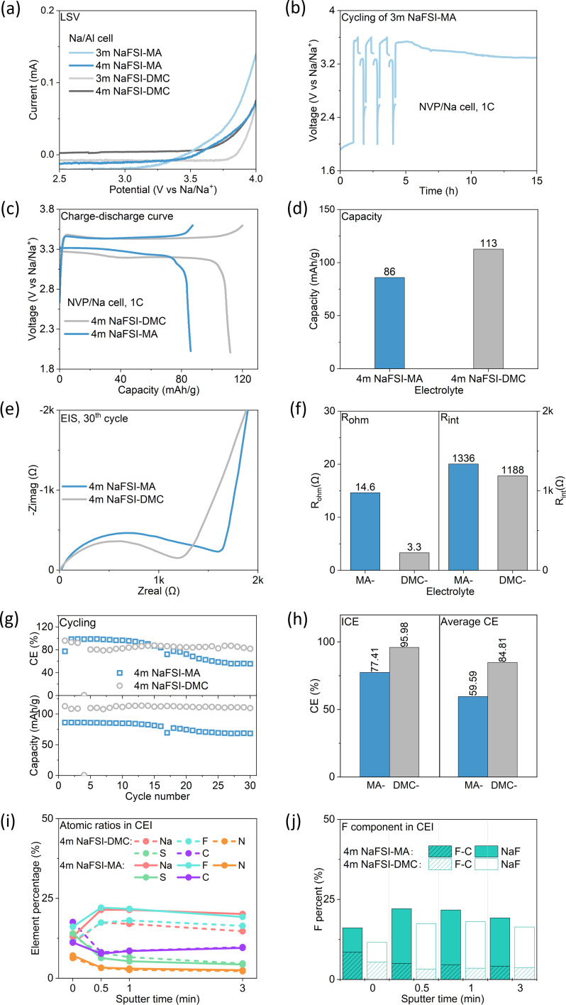
The anodic stability of the electrolyte, i.e., the resistance against oxidation under high voltage, was examined by linear sweep voltammetry (LSV) in Na/Al half-cells (Fig. 7a). 3 m NaFSI-MA and 3 m NaFSI-DMC start to oxidize at 3.2 V and 3.6 V, respectively, suggesting that MA-based electrolytes are less resistant to oxidation than DMC-based electrolytes. Consequently, 3 m NaFSI-MA electrolyte failed in NVP/Na cells (Fig. 7b) and cannot be charged beyond 3.5 V. A long plateau at ∼3.3 V is observed which indicates continuous electrolyte oxidation. Apparently, the electrolyte decomposition fails to form a stable CEI on the cathode surface. By increasing the concentration to 4 m the anodic stability of NaFSI-MA can be improved to 3.5 V (Fig. 7a) and it enables a successful charge to 3.6 V (Fig. 7c). However, a lower capacity (93 mA h g−1vs. 113 mA h g−1) is observed (Fig. 7d), consistent with its higher internal resistance (Fig. 7e and f). It also exhibits a lower capacity retention (79.46% at the 30th cycle) than that of NaFSI-DMC (97.23% at the 30th cycle) (Fig. 7g). Meanwhile, 4 m NaFSI-MA electrolyte shows lower ICE (77.41%) and average CE (59.59%) compared to its DMC counterpart (95.98% and 84.81%) (Fig. 7g and h), suggesting more electrolyte consumption during charging, consistent with its inferior anodic stability. As evidenced by the XPS results (Fig. 7i and j), the CEI of NaFSI-MA electrolyte shows more anion decomposition product, NaF, than that of NaFSI-DMC electrolyte. Furthermore, we conducted the same charge–discharge process for higher NaFSI concentration (8 m NaFSI-MA) using NVP/Na cells. The results (Fig. S7†) show improved CE, demonstrating that high salt concentration can inhibit side reactions like electrolyte decomposition. While the 8 m electrolyte shows lower capacity in the first four cycles, its capacity increases in the following cycles and stabilizes at around 90 mA h g−1, which is higher than that of the 4 m electrolyte (around 68 mA h g−1). These results indicate salt decomposition contributes to the CEI formation, and the anion-derived CEI is evolving with cycling in the high concentration electrolyte. Although the 8 m electrolyte shows lower conductivity than the 4 m electrolyte, its superior interface can offset that. Overall, we can draw a similar conclusion to the HC/Na half-cell studies: despite carboxylate-based electrolytes possessing better bulk properties than their carbonate counterparts, their electrochemical performance is compromised due to their inferior interfacial properties, including the poor ability to form an interphase, more electrolyte decomposition, and the resulting high interfacial resistance.
Fig. 7. Solvent effect on cathode performance. (a) LSV of NaFSI-MA and NaFSI-DMC in an Na/Al cell; (b) voltage–time profile of an NVP/Na cell using 3 m NaFSI-MA electrolyte; (c–h) comparison of electrochemical performance and internal resistance between 4 m NaFSI-MA and 4 m NaFSI-DMC for the NVP/Na cell, discharged and charged at 1C rate. (c) Charging and discharging profiles of the 2nd cycle; (d) capacity; (e) EIS curve of each cell after the 5th cycle; (f) Rohm and Rint after the 30th cycle; (g) CE (top) and capacity (bottom) with cycling; (h) ICE and average CE (21st–30th); (i and j) CEI component analyzed by XPS.
Low temperature performance
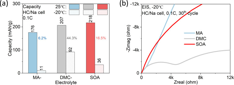
Finally, we examined the low temperature performance of NaFSI-MA and compared it with that of NaFSI-DMC and SOA electrolyte in HC/Na half cells (Fig. 8a). Respectively, at −20 °C they keep 6.2%, 44.3% and 16.5% of their room-temperature capacity. The unsatisfactory low temperature capacity of SOA electrolyte can be explained by its low conductivity, which decreases from 10.42 mS cm−1 at room temperature to 0.79 mS cm−1 at −20 °C (Fig. 5a). In contrast, NaFSI-MA shows the worst capacity retention at low temperatures because of its highest interfacial resistance (Fig. 8b). Meanwhile, NaFSI-DMC shows a moderate conductivity (2.43 mS cm−1) at low temperatures and interfacial resistance, which leads to the highest low-temperature performance.
Fig. 8. Low temperature performance. (a) Capacity comparison between 3 m NaFSI-MA, 3 m NaFSI-DMC and SOA electrolyte for the HC/Na cell both at 25 °C and −20 °C, discharged and charged at 0.1C rate. (b) EIS curve of the cell cycled at −20 °C after 30 cycles.
Discussion
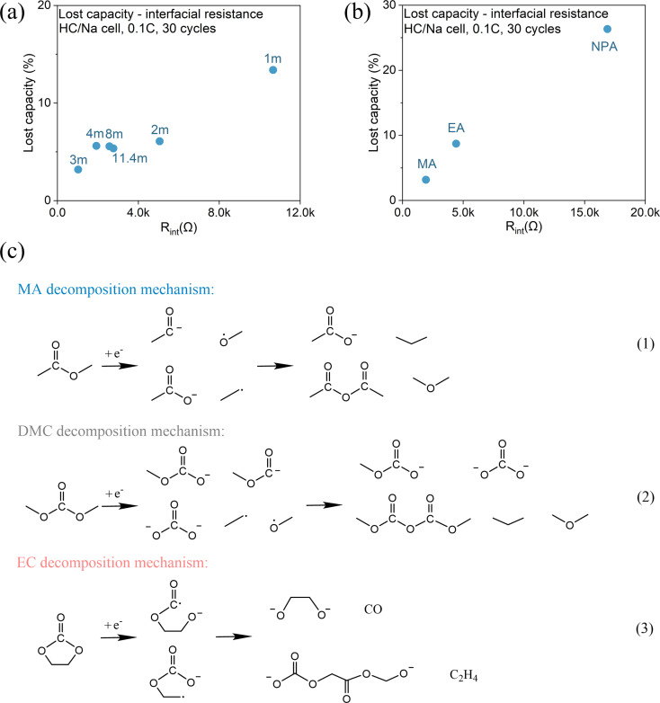
In summary, we presented a systematic investigation of carboxylate-based electrolytes for SIBs and examined the effect of salt chemistry, concentration, and molecular structure on the electrochemical performance of both HC/Na and NVP/Na half-cells. Carboxylate-based electrolytes demonstrate better transport properties (conductivity) at both room and low temperatures than their carbonate counterparts due to their lower melting point, lower viscosity and stronger polarity, as well as comparable CE after SEI formation. However, they are more reactive, which leads to low ICE, larger interfacial resistance, and lower capacity. The interfacial resistance of the HC/Na half-cells in the carboxylate-based electrolytes is 5–8 times higher than that in the carbonate-based electrolytes, and 1–2 orders of magnitude higher than that in the SOA SIB electrolyte. The large interfacial resistance in the carboxylate-based electrolytes is likely a result of the thick and resistive SEI due to a large amount of irreversible electrolyte decomposition. This hypothesis is confirmed by the low ICE and a linear correlation between the accumulated lost capacity and the total interfacial resistance (Fig. 9a and b). Our study also shows that carboxylate-based electrolytes can form a stable SEI after cycling with comparable average CE to carbonate-based electrolytes and SOA electrolytes. However, this can only be achieved when an anion participates in SEI formation at a salt concentration >2 m.
Fig. 9. Correlation between interfacial resistance with total lost capacity after cycling: (a) concentration effect and (b) chain length effect. (c) Reductive decomposition mechanism of MA, DMC and EC.
To understand the difference between carboxylates and carbonates, the reductive decomposition mechanisms of MA45 (representative carboxylate), DMC46,47 (representative carbonate) and EC43 (indispensable component in SOA electrolytes) are reviewed and compared. As shown in Fig. 9c, they follow different reaction routes and generate different products. Alkyl carbonates formed by EC decomposition, such as NEDC in SIBs and LEDC in LIBs, are believed to be the key ingredient to form a stable SEI, because of their propensity to form a multimer conformation network.43 In contrast, extensive studies have demonstrated that carboxylates,12,48 including linear carbonates,23,44 are incapable of forming a stable interphase. This deficiency implies that their decomposition products are less effective in inhibiting continuous electrolyte reduction, evidenced by the lower ICE and higher interfacial resistance in MA- and DMC- based electrolytes than those of SOA electrolyte. In addition, considering that carboxylates exhibit higher dielectric constants than their carbonate counterparts, it can be inferred that their SEI is more prone to dissolve. Consequently, the SEI formed in a carboxylate may experience continuous dissolution–regeneration, which results in larger interfacial resistance and continuous capacity loss. This provides a plausible explanation for the lower CE of carboxylate electrolytes than their carbonate counterparts.
Since carboxylates alone cannot form a stable interphase, the role of salt becomes crucial. We demonstrate that by using NaFSI salt, it is possible to make carboxylates compatible with HC and achieve high CE. In contrast, electrolytes with other salts are not compatible with HC and exhibit irreversible electrolyte decomposition. Previous studies9 have shown that the organic content (mainly formed by solvent decomposition) of the SEI on sodiated hard carbon decreases in the order: NaPF6 > NaClO4 > NaTFSI > NaFSI, which suggests that the first three anions are less effective in contributing to SEI formation compared to NaFSI. This further explains the capability of FSI− to form a stable SEI compared to other salts. A notable observation in our results is the improvement of ICE and capacity with NaFSI concentration. This enhancement can be ascribed to the unique feature of high concentration electrolyte. As the salt concentration increases, more anions enter the solvation shell, driving the LUMO shift from the solvent to the anion and making anions more prone to decompose.27 As a result, the SEI formed in high concentration electrolytes exhibits an inorganic-rich, anion-derived composition.
So far there has been no single solvent that can simultaneously possess a low melting point (to prevent freezing at low temperatures), high dielectric permittivity and low viscosity (to facilitate ion transport), while still enabling both a stable SEI and CEI. Carboxylates have shown potential to provide superior mass transport properties in the bulk at both room and low temperatures. Their poor ability to form a stable interface can potentially be addressed by mixing co-solvent and/or additives, which will be the topics of future research.
Conclusion
In conclusion, to evaluate the potential of carboxylate-based electrolytes in enhancing the low-temperature performance of SIBs, we systematically examined the effect of salt, concentration and solvent molecular structure and compared the results with those of carbonate-based electrolytes. We found carboxylates enable high electrolyte conductivities, especially at low temperatures, due to their favorable properties (i.e., low melting point, low viscosity and high dielectric constant). However, carboxylates alone are inadequate to form a stable interphase due to their high reactivity, leading to low CE and fast capacity degradation. By facilitating anion-rich Na+ solvation via increasing salt concentration, it is possible to leverage anion decomposition to form an inorganic-rich SEI that can stabilize the interface, thereby permitting stable cycling of SIBs. However, the large extent of electrolyte decomposition leads to very large interfacial resistance, which significantly compromises the low-temperature performance of the carboxylate electrolytes.
At a fundamental level, the comprehensive results presented in this work establish a clear chemistry–property–performance correlation of carboxylate-based electrolytes for SIB application. Despite the studied system not offering great electrochemical performance, the obtained knowledge sheds light on the fundamental nature of the unique advantages and limitations of carboxylate-based electrolytes, which provides valuable insights for rational design. Based on the discovery, future efforts on carboxylate electrolyte design should focus on interphase engineering to curb their poor ability to form a stable interphase and utilize their advantageous bulk transport properties. Experience from LIB electrolyte design, including co-solvent and additive engineering, can be leveraged to accelerate progress in this endeavor.
Methods
Electrolytes and electrodes
The electrolytes were prepared by dissolving sodium fluoroborate (NaBF4, 99.9%, Aladdin), sodium trifluoromethanesulfonate (NaOTf, 99.5%, Solvionic), sodium perchlorate (NaClO4, 98%, Thermo Scientific Chemicals), sodium hexafluorophosphate (NaPF6, 99+%, Thermo Scientific Chemicals), sodium bis(trifluoromethanesulfonyl)imide (NaTFSI, 99.5%, Solvionic), and sodium bis(fluorosulfonyl)imide (NaFSI, 99.9%, Solvionic) respectively as per the required concentrations in various carboxylate and carbonate solvents in an argon-filled glovebox. All the salts were dried in a vacuum at 100 °C for 24 h, and the solvents were dried over fresh 3 Å molecular sieves for three days. The representative SOA electrolyte, 1 M NaPF6-EC/DEC 1 : 1 by volume, was bought from Canrd, China.
The hard carbon anode was prepared as follows: a slurry made up of 90 wt% hard carbon powder (Kureha Co), 5 wt% carbon black, and 5 wt% poly(vinylidene fluoride) in N-methyl-2-pyrrolidone solution was pasted onto Al foil. This electrode was dried overnight at room temperature, and then punched into circles with a 5/16-inch diameter. The HC loading amount was 1.2–1.8 mg cm−2, and its theoretical capacity was 250 ± 30 mA h g−1 on the weight basis of the HC active material. The NVP powder was purchased from Kejing Star Technology Co., Ltd (Shenzhen). Then, it was well mixed with poly(vinylidene fluoride) and carbon black (8 : 1 : 1 wt%), and further coated on aluminum foil. This electrode was dried overnight at room temperature, and then punched into circles with a 5/16-inch diameter. The NVP loading amount was 1.2–1.4 mg cm−2. Both the HC anode and NVP cathode were dried in a vacuum at 100 °C overnight before use.
Electrochemical tests
All experiments were conducted using 2023-type coin cells assembled in an argon-filled glovebox, where both the moisture and oxygen contents were maintained at below 1 ppm. The coin cells used a glassy fiber membrane as the separator and thick Na foil as the counter electrode, and 40 μl of electrolyte. The CV tests were conducted using a Gamry Interface 1010T. The scan range is within 0.001–1 V with a 0.5 mV s−1 scan rate. The charge–discharge performances were carried out on a Landt CT3001A battery test system. For the HC/Na half-cell cycling, a 0.1C rate charging and discharging protocol was used within the voltage range of 0.001–2 V. 1C rate corresponds to 300 mA h g−1 on the weight basis of the HC active material. Each sample was tested twice in parallel to ensure the accuracy of the results. For low temperature testing of HC/Na, cells were discharged and charged for 5 cycles at 0.1C rate at room temperature first, and then soaked in a low-temperature thermostatic bath to maintain them at −20 °C for 2 hours. Subsequently, the as-made cells were cycled at 0.1C rate. For NVP/Na half cells, cycling was performed at 2.0–3.6 V at 1C rate.
The conductivity of the electrolyte was assessed using electrochemical impedance spectroscopy (EIS) using a Gamry Interface 1010T. Symmetrical cells (SS|electrolyte|SS, SS denotes stainless steel) were assembled with one piece of glass fiber membrane soaked with electrolyte (40 μl) and two pieces of stainless steel. This cell was used for conducting a potentiostatic EIS test in the frequency range of 1 to 200 000 Hz. The ionic conductivity of the electrolyte was estimated using the following equation: σ = (1/R) × (l/S), where R is the resistance, S is the area of the membrane, and σ is the ionic conductivity. For the low-temperature conductivity test, the cell was held in an oil bath capable of cooling down to −20 °C.
Characterization
Fourier-transform infrared spectroscopy (FT-IR) was performed using a Nicolet iS50 FTIR spectrometer with a diamond ATR crystal, on which the electrolyte was placed directly on the window testing holders during the test. All FTIR spectra were deconvoluted with the Gauss Amp function using PeakFit software.
X-ray photoelectron spectroscopy (XPS) and argon sputtering were performed using a Kratos Axis Ultra DLD. Samples were transferred through the antechamber to avoid any air contact. An area of 300 μm × 700 μm was irradiated using a filament voltage of 15 kV, an emission current of 8 mA, and a pass energy of 40 eV for high-resolution scans and 160 eV for the low-resolution survey scans. For the XPS sputter depth profiling measurements, a sputter crater of 3 mm × 3 mm area was produced by the Ar+ ion beam using an emission current of 20 mA and a filament voltage of 4 kV. The XPS spectra were calibrated by referencing sp2 carbon to 284.0 eV.
Data availability
All data are available in the manuscript and in the ESI.†
Author contributions
Yunan Qin designed the experiment plans, analyzed all results and wrote the manuscript. Seong-Gyu Choi and Lucia Mason prepared the electrolytes and assembled coin cells. Jing Liu assisted in the spectral analysis, and Zongjian Li contributed to the interpretation of the experimental results. Tao Gao supervised and revised the manuscript. All authors discussed the results and commented on the manuscript.
Conflicts of interest
There are no conflicts to declare.
Supplementary Material
Acknowledgments
This work was supported by the National Science Foundation under grant no. 2247407. We also acknowledge the contribution from Michael Barkdull, who was an undergraduate research assistant in our lab.
Electronic supplementary information (ESI) available. See DOI: https://doi.org/10.1039/d4sc02266a
References
- Veronika Henze. Lithium-ion Battery Pack Prices Rise for First Time to an Average of $151 per kW h, https://about.bnef.com/blog/lithium-ion-battery-pack-prices-rise-for-first-time-to-an-average-of-151-kwh/
- Tarascon J. M. Is Lithium the New Gold? Nat. Chem. 2010;2(6):510. doi: 10.1038/nchem.680. doi: 10.1038/nchem.680. [DOI] [PubMed] [Google Scholar]
- Grosjean C. Herrera Miranda P. Perrin M. Poggi P. Assessment of World Lithium Resources and Consequences of Their Geographic Distribution on the Expected Development of the Electric Vehicle Industry. Renewable Sustainable Energy Rev. 2012;16(3):1735–1744. doi: 10.1016/j.rser.2011.11.023. doi: 10.1016/j.rser.2011.11.023. [DOI] [Google Scholar]
- Vikström H. Davidsson S. Höök M. Lithium Availability and Future Production Outlooks. Appl. Energy. 2013;110:252–266. doi: 10.1016/j.apenergy.2013.04.005. doi: 10.1016/j.apenergy.2013.04.005. [DOI] [Google Scholar]
- Peters J. Buchholz D. Passerini S. Weil M. Life Cycle Assessment of Sodium-Ion Batteries. Energy Environ. Sci. 2016;9(5):1744–1751. doi: 10.1039/c6ee00640j. doi: 10.1039/c6ee00640j. [DOI] [Google Scholar]
- He H. Sun D. Tang Y. Wang H. Shao M. Understanding and Improving the Initial Coulombic Efficiency of High-Capacity Anode Materials for Practical Sodium Ion Batteries. Energy Storage Mater. 2019;23(March):233–251. doi: 10.1016/j.ensm.2019.05.008. doi: 10.1016/j.ensm.2019.05.008. [DOI] [Google Scholar]
- Ponrouch A. Dugas R. Iermakova D. Iermakova D. I. Dugas R. Palac M. R. On the Comparative Stability of Li and Na Metal Anode Interfaces in Conventional Alkyl Carbonate Electrolytes On the Comparative Stability of Li and Na Metal Anode Interfaces in Conventional Alkyl Carbonate Electrolytes. J. Electrochem. Soc. 2015;162:A7060. doi: 10.1149/2.0091513jes. doi: 10.1149/2.0091513jes. [DOI] [Google Scholar]
- Mogensen R. Brandell D. Younesi R. Solubility of the Solid Electrolyte Interphase (SEI) in Sodium Ion Batteries. ACS Energy Lett. 2016;1:1173–1178. doi: 10.1021/acsenergylett.6b00491. doi: 10.1021/acsenergylett.6b00491. [DOI] [Google Scholar]
- Eshetu G. G. Diemant T. Hekmatfar M. Grugeon S. Behm R. J. Laruelle S. Armand M. Passerini S. Impact of the Electrolyte Salt Anion on the Solid Electrolyte Interphase Formation in Sodium Ion Batteries. Nano Energy. 2019;55:327–340. doi: 10.1016/j.nanoen.2018.10.040. doi: 10.1016/j.nanoen.2018.10.040. [DOI] [Google Scholar]
- Liu X. Zheng X. Qin X. Deng Y. Dai Y. Zhao T. Wang Z. Yang H. Luo W. Temperature-Responsive Solid-Electrolyte-Interphase Enabling Stable Sodium Metal Batteries in a Wide Temperature Range. Nano Energy. 2022;103:107746. doi: 10.1016/j.nanoen.2022.107746. doi: 10.1016/j.nanoen.2022.107746. [DOI] [Google Scholar]
- Smart M. C. Ratnakumar B. V. Surampudi S. Use of Organic Esters as Cosolvents in Electrolytes for Lithium-Ion Batteries with Improved Low Temperature Performance. J. Electrochem. Soc. 2002;149(4):A361. doi: 10.1149/1.1453407. doi: 10.1149/1.1453407. [DOI] [Google Scholar]
- Smart M. C. Ratnakumar B. V. Chin K. B. Whitcanack L. D. Lithium-Ion Electrolytes Containing Ester Cosolvents for Improved Low Temperature Performance. J. Electrochem. Soc. 2010;157(12):A1361. doi: 10.1149/1.3501236. doi: 10.1149/1.3501236. [DOI] [Google Scholar]
- Desai P. Abou-Rjeily J. Tarascon J. M. Mariyappan S. Practicality of Methyl Acetate as a Co-Solvent for Fast Charging Na-Ion Battery Electrolytes. Electrochim. Acta. 2022;416:140217. doi: 10.1016/j.electacta.2022.140217. doi: 10.1016/j.electacta.2022.140217. [DOI] [Google Scholar]
- Tang Z. Wang H. Wu P. Zhou S. Huang Y. Zhang R. Sun D. Tang Y. Wang H. Electrode–Electrolyte Interfacial Chemistry Modulation for Ultra-High Rate Sodium-Ion Batteries. Angew. Chem., Int. Ed. 2022;61:e202200475. doi: 10.1002/anie.202200475. doi: 10.1002/anie.202200475. [DOI] [PubMed] [Google Scholar]
- Li Z. Liu J. Bi X. Qin Y. Gao T. Single-Oxygen Linear Ether (SOLE) Based Electrolytes for Fast-Charging and Low-Temperature Li-Ion Batteries. J. Mater. Chem. A. 2023;11(37):19996–20010. doi: 10.1039/d3ta01956j. doi: 10.1039/d3ta01956j. [DOI] [Google Scholar]
- Mo Y. Liu G. Yin Y. Tao M. Chen J. Peng Y. Wang Y. Fluorinated Solvent Molecule Tuning Enables Fast-Charging and Low-Temperature Lithium-Ion. Batteries. 2023;2301285:1–13. doi: 10.1002/aenm.202301285. [DOI] [Google Scholar]
- Zhou J. Wang Y. Wang J. Liu Y. Li Y. Cheng L. Ding Y. Dong S. Zhu Q. Tang M. Wang Y. Bi Y. Sun R. Wang Z. Wang H. Low-Temperature and High-Rate Sodium Metal Batteries Enabled by Electrolyte Chemistry. Energy Storage Mater. 2022;50:47–54. doi: 10.1016/j.ensm.2022.05.005. doi: 10.1016/j.ensm.2022.05.005. [DOI] [Google Scholar]
- Cho Y. G. Li M. Holoubek J. Li W. Yin Y. Meng Y. S. Chen Z. Enabling the Low-Temperature Cycling of NMC‖Graphite Pouch Cells with an Ester-Based Electrolyte. ACS Energy Lett. 2021;6(5):2016–2023. doi: 10.1021/acsenergylett.1c00484. doi: 10.1021/acsenergylett.1c00484. [DOI] [Google Scholar]
- Logan E. R. Hall D. S. Cormier M. M. E. Taskovic T. Bauer M. Hamam I. Hebecker H. Molino L. Dahn J. R. Ester-Based Electrolytes for Fast Charging of Energy Dense Lithium-Ion Batteries. J. Phys. Chem. C. 2020;124(23):12269–12280. doi: 10.1021/acs.jpcc.0c02370. doi: 10.1021/acs.jpcc.0c02370. [DOI] [Google Scholar]
- Petibon R. Harlow J. Le D. B. Dahn J. R. The Use of Ethyl Acetate and Methyl Propanoate in Combination with Vinylene Carbonate as Ethylene Carbonate-Free Solvent Blends for Electrolytes in Li-Ion Batteries. Electrochim. Acta. 2015;154:227–234. doi: 10.1016/j.electacta.2014.12.084. doi: 10.1016/j.electacta.2014.12.084. [DOI] [Google Scholar]
- Li Z. Yao N. Li Z. Yao N. Yu L. Yao Y. Jin C. Yang Y. Xiao Y. Yue X. Inhibiting Gas Generation to Achieve Ultralong- Lifespan Lithium-Ion Batteries at Low Temperatures to Achieve Ultralong-Lifespan. Matter. 2023:1–19. doi: 10.1016/j.matt.2023.04.012. [DOI] [Google Scholar]
- Mogensen R. Colbin S. Younesi R. An Attempt to Formulate Non-Carbonate Electrolytes for Sodium-Ion Batteries. Batteries Supercaps. 2021;4(5):791–814. doi: 10.1002/batt.202000252. doi: 10.1002/batt.202000252. [DOI] [Google Scholar]
- Salomon M. Lin H. Plichta E. J. Hendrickson M. Temperature Effects on Li-Ion Cell Performance. Adv. Lithium-Ion Batteries. 2002:309–344. doi: 10.1007/0-306-47508-1_12. [DOI] [Google Scholar]
- Tan S., Shadike Z., Cai X., Lin R., Kludze A., Borodin O., Lucht B. L., Wang C., Hu E., Xu K. and Yang X. Q., Review on Low-Temperature Electrolytes for Lithium-Ion and Lithium Metal Batteries, Springer Nature Singapore, 2023, vol 6, 10.1007/s41918-023-00199-1 [DOI] [Google Scholar]
- Smart M. C. Lucht B. L. Dalavi S. Krause F. C. Ratnakumar B. V. The Effect of Additives upon the Performance of MCMB/LiNixCo1−xO2 Li-Ion Cells Containing Methyl Butyrate-Based Wide Operating Temperature Range Electrolytes. J. Electrochem. Soc. 2012;159(6):A739–A751. doi: 10.1149/2.058206jes. doi: 10.1149/2.058206jes. [DOI] [Google Scholar]
- Wang J. Yamada Y. Sodeyama K. Watanabe E. Takada K. Tateyama Y. Yamada A. Fire-Extinguishing Organic Electrolytes for Safe Batteries. Nat. Energy. 2018;3(1):22–29. doi: 10.1038/s41560-017-0033-8. doi: 10.1038/s41560-017-0033-8. [DOI] [Google Scholar]
- Yamada Y. Wang J. Ko S. Watanabe E. Yamada A. Advances and Issues in Developing Salt-Concentrated Battery Electrolytes. Nat. Energy. 2019;4(4):269–280. doi: 10.1038/s41560-019-0336-z. doi: 10.1038/s41560-019-0336-z. [DOI] [Google Scholar]
- Wang J. Yamada Y. Sodeyama K. Chiang C. H. Tateyama Y. Yamada A. Superconcentrated Electrolytes for a High-Voltage Lithium-Ion Battery. Nat. Commun. 2016;7:1–9. doi: 10.1038/ncomms12032. [DOI] [PMC free article] [PubMed] [Google Scholar]
- Molaiyan P. Dos Reis G. S. Karuppiah D. Subramaniyam C. M. García-Alvarado F. Lassi U. Recent Progress in Biomass-Derived Carbon Materials for Li-Ion and Na-Ion Batteries—A Review. Batteries. 2023;9(2):116. doi: 10.3390/batteries9020116. doi: 10.3390/batteries9020116. [DOI] [Google Scholar]
- He Y. Li H. Recent Research Process of Carbon Engineering on Na3V2(PO4)3 for Sodium-Ion Battery Cathodes: A Mini Review. Electron. Mater. 2023;4(1):17–32. doi: 10.3390/electronicmat4010003. doi: 10.3390/electronicmat4010003. [DOI] [Google Scholar]
- Tian Z. Zou Y. Liu G. Wang Y. Yin J. Ming J. Alshareef H. N. Electrolyte Solvation Structure Design for Sodium Ion Batteries. Adv. Sci. 2022;9(22):1–29. doi: 10.1002/advs.202201207. [DOI] [PMC free article] [PubMed] [Google Scholar]
- Yamada Y. Yamada A. Review—Superconcentrated Electrolytes for Lithium Batteries. J. Electrochem. Soc. 2015;162(14):A2406–A2423. doi: 10.1149/2.0041514jes. doi: 10.1149/2.0041514jes. [DOI] [Google Scholar]
- Cao X. Jia H. Xu W. Zhang J.-G. Review—Localized High-Concentration Electrolytes for Lithium Batteries. J. Electrochem. Soc. 2021;168(1):010522. doi: 10.1149/1945-7111/abd60e. doi: 10.1149/1945-7111/abd60e. [DOI] [Google Scholar]
- Li Y. Yang Y. Lu Y. Zhou Q. Qi X. Meng Q. Rong X. Chen L. Hu Y. S. Ultralow-Concentration Electrolyte for Na-Ion Batteries. ACS Energy Lett. 2020;5(4):1156–1158. doi: 10.1021/acsenergylett.0c00337. doi: 10.1021/acsenergylett.0c00337. [DOI] [Google Scholar]
- Stevens D. A. Dahn J. R. High Capacity Anode Materials for Rechargeable Sodium-Ion Batteries. J. Electrochem. Soc. 2000;147(4):1271. doi: 10.1149/1.1393348. doi: 10.1149/1.1393348. [DOI] [Google Scholar]
- Stevens D. A. Dahn J. R. The Mechanisms of Lithium and Sodium Insertion in Carbon Materials. J. Electrochem. Soc. 2001;148(8):A803. doi: 10.1149/1.1379565. doi: 10.1149/1.1379565. [DOI] [Google Scholar]
- Dahbi M. Yabuuchi N. Kubota K. Tokiwa K. Komaba S. Negative Electrodes for Na-Ion Batteries. Phys. Chem. Chem. Phys. 2014;16(29):15007–15028. doi: 10.1039/c4cp00826j. doi: 10.1039/c4cp00826j. [DOI] [PubMed] [Google Scholar]
- Sivaraman B. Nair B. G. Lo J. I. Kundu S. Davis D. Prabhudesai V. Raja Sekhar B. N. Mason N. J. Cheng B. M. Krishnakumar E. Vacuum Ultraviolet and Infrared Spectra of Condensed Methyl Acetate on Cold Astrochemical Dust Analogs. Astrophys. J. 2013;778(2):2–6. doi: 10.1088/0004-637X/778/2/157. [DOI] [Google Scholar]
- Huang J. Hollenkamp A. F. Thermal Behavior of Ionic Liquids Containing the FSI Anion and the Li+ Cation. J. Phys. Chem. C. 2010;114(49):21840–21847. doi: 10.1021/jp107740p. doi: 10.1021/jp107740p. [DOI] [Google Scholar]
- Yamada Y. Furukawa K. Sodeyama K. Kikuchi K. Yaegashi M. Tateyama Y. Yamada A. Unusual Stability of Acetonitrile-Based Superconcentrated Electrolytes for Fast-Charging Lithium-Ion Batteries. J. Am. Chem. Soc. 2014;136(13):5039–5046. doi: 10.1021/ja412807w. doi: 10.1021/ja412807w. [DOI] [PubMed] [Google Scholar]
- Smart M. C. Ratnakumar B. V. Surampudi S. Wang Y. Zhang X. Greenbaum S. G. Hightower A. Ahn C. C. Fultz B. Irreversible Capacities of Graphite in Low-Temperature Electrolytes for Lithium-Ion Batteries. J. Electrochem. Soc. 1999;146(11):3963–3969. doi: 10.1149/1.1392577. doi: 10.1149/1.1392577. [DOI] [Google Scholar]
- Eshetu G. G. Grugeon S. Kim H. Jeong S. Wu L. Gachot G. Laruelle S. Armand M. Passerini S. Comprehensive Insights into the Reactivity of Electrolytes Based on Sodium Ions. ChemSusChem. 2016;9(5):462–471. doi: 10.1002/cssc.201501605. doi: 10.1002/cssc.201501605. [DOI] [PubMed] [Google Scholar]
- Xu K. Von Cresce A. Interfacing Electrolytes with Electrodes in Li Ion Batteries. J. Mater. Chem. 2011;21(27):9849–9864. doi: 10.1039/c0jm04309e. doi: 10.1039/c0jm04309e. [DOI] [Google Scholar]
- Xia X. Dahn J. R. Study of the Reactivity of Na/Hard Carbon with Different Solvents and Electrolytes. J. Electrochem. Soc. 2012;159(5):A515–A519. doi: 10.1149/2.jes111637. doi: 10.1149/2.jes111637. [DOI] [Google Scholar]
- Lei S. Zeng Z. Yan H. Qin M. Liu M. Wu Y. Zhang H. Cheng S. Xie J. Nonpolar Cosolvent Driving LUMO Energy Evolution of Methyl Acetate Electrolyte to Afford Lithium-Ion Batteries Operating at −60 °C. Adv. Funct. Mater. 2023;33(34):2301028. doi: 10.1002/adfm.202301028. doi: 10.1002/adfm.202301028. [DOI] [Google Scholar]
- Huang J. Guo X. Du X. Lin X. Huang J. Tan H. Zhu Y. Zhang B. Nanostructures of Solid Electrolyte Interphases and Their Consequences for Microsized Sn Anodes in Sodium Ion Batteries. Environ. Sci. 2019:1550–1557. doi: 10.1039/c8ee03632b. [DOI] [Google Scholar]
- Michan A. L. Leskes M. Grey C. P. Voltage Dependent Solid Electrolyte Interphase Formation in Silicon Electrodes: Monitoring the Formation of Organic Decomposition Products. Chem. Mater. 2016;28(1):385–398. doi: 10.1021/acs.chemmater.5b04408. doi: 10.1021/acs.chemmater.5b04408. [DOI] [Google Scholar]
- Li J. Li H. Ma X. Stone W. Glazier S. Logan E. Tonita E. M. Gering K. L. Dahn J. R. Methyl Acetate as a Co-Solvent in NMC532/Graphite Cells. J. Electrochem. Soc. 2018;165(5):A1027–A1037. doi: 10.1149/2.0861805jes. doi: 10.1149/2.0861805jes. [DOI] [Google Scholar]
Associated Data
This section collects any data citations, data availability statements, or supplementary materials included in this article.
Supplementary Materials
Data Availability Statement
All data are available in the manuscript and in the ESI.†


