Abstract
The coupling electrosynthesis involving CO2 upgrade conversion is of great significance for the sustainable development of the environment and energy but is challenging. Herein, we exquisitely constructed the self‐supported bimetallic array superstructures from the Cu(OH)2 array architecture precursor, which can enable high‐performance coupling electrosynthesis of formate and adipate at the anode and the cathode, respectively. Concretely, the faradaic efficiencies (FEs) of CO2‐to‐formate and cyclohexanone‐to‐adipate conversion simultaneously exceed 90% at both electrodes with excellent stabilities. Such high‐performance coupling electrosynthesis is highly correlated with the porous nanosheet array superstructure of CuBi alloy as the cathode and the nanosheet‐on‐nanowire array superstructure of CuNi hydroxide as the anode. Moreover, compared to the conventional electrolysis process, the cell voltage is substantially reduced while maintaining the electrocatalytic performance for coupling electrosynthesis in the two‐electrode electrolyzer with the maximal FEformate and FEadipate up to 94.2% and 93.1%, respectively. The experimental results further demonstrate that the bimetal composition modulates the local electronic structures, promoting the reactions toward the target products. Prospectively, our work proposes an instructive strategy for constructing adaptive self‐supported superstructures to achieve efficient coupling electrosynthesis.
Keywords: coupling electrosynthesis, electrocatalysis, superstructures
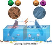
The self‐supported bimetallic array superstructures were constructed for high‐performance coupling electrosynthesis of formate and adipate at the anode and cathode, respectively. Thanks to the unique nanostructure features and the promotion effect of adaptive reactions, the resulting electrocatalysts delivered remarkable performance for both CO2‐to‐formate and cyclohexanone‐to‐adipate conversion with high Faradaic efficiencies and current densities.
1. INTRODUCTION
Different from other energy and environment‐related reactions, electrochemical carbon dioxide reduction to produce valuable products can realize efficient utilization of intermittent renewable energy, which is an effective way to reduce the concentration of CO2 in the atmosphere and promote a sustainable closed carbon cycle.[ 1 ] It holds great significance in mitigating global warming and reducing the depletion of traditional energy resources.[ 2 ] Specifically, a typical CO2 electroconversion system includes a cathodic CO2 reduction reaction (CO2RR) and the anodic oxygen evolution reaction (OER). However, the slow OER necessitates a high onset potential, significantly limiting the rate of electrochemical CO2RR and resulting in substantial energy losses.[ 3 ] As a result, to fully harness the electrical energy, a more kinetically favorable oxidation reaction should be used to replace the OER, which is also expected to produce value‐added products.[ 4 ]
Adipic acid is a pivotal molecule in the polymer industry, possessing a broad range of applications and experiencing high demand.[ 5 ] However, the current method for industrial adipic acid preparation relies on the thermo‐catalytic oxidation of KA oil (a combination of cyclohexanone and cyclohexanol) under harsh conditions involving the use of highly corrosive nitric acid as an oxidant. This process causes significant energy consumption and results in hazardous gas emissions.[ 6 ] Therefore, it is highly desirable to seek a more environmentally friendly and sustainable adipic acid synthesis process.[ 7 ] Electrocatalytic cyclohexanone oxidation reaction (CHOR) driven by electrical energy offers an excellent opportunity for adipic acid production toward a more sustainable chemical industry.[ 8 ] Particularly and prospectively, coupling electrochemical CO2RR with CHOR can not only reduce the energy input of the electrolysis system but also realize the green electrochemical synthesis of adipic acid (Scheme 1A). However, the key to achieving this coupling electrosynthesis lies in developing highly active and stable electrocatalysts. Notably, among many materials, the self‐supported electrocatalytic materials with bimetallic configuration can realize the accurate integration of morphology engineering and electronic structure engineering,[ 9 ] which are expected to propel efficient coupling of cathodic CO2RR and anodic CHOR for integrated industrial production; however, there is a lack of in‐depth systematic exploration.
SCHEME 1.
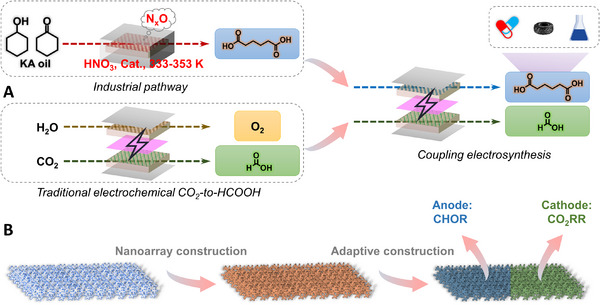
A, Schematic illustration of upgrading the traditional (electro)synthesis to coupling electrosynthesis of formate and adipate, and B, fabricated illustration of electrocatalysts for coupling electrosynthesis.
Herein, according to the characteristics of cathodic CO2RR and anodic CHOR, we hired Cu(OH)2 nanowire arrays grown on copper foam (CF) as the three‐dimensional self‐supported substrate, and Bi (one of the most promising active elements for electrochemical CO2‐to‐formate conversion[ 10 ]) and Ni species were, respectively, introduced to construct suitable electrocatalysts (namely, eBiCu/CF and CuxNi1−x(OH)2/CF) (Scheme 1B). Expectedly, in situ electrochemically reconstructed eBiCu/CF consists of porous and ultrathin alloy nanosheets with an open network structure, which achieves more than 90% faradaic efficiency for formate (FEformate) in a wide potential range, far superior to the counterpart electrocatalysts, and CuxNi1−x(OH)2/CF features a nanosheet‐on‐nanowire array structure with ultrathin hydroxide nanosheets interconnected and welded on the surface of nanowires, which exhibits excellent electrocatalytic performance for CHOR with faradaic efficiency of adipate (FEadipate) up to 95.7%. In particular, the coupling electrosynthesis system of CO2RR//CHOR was further assembled to simultaneously achieve >90% FEformate and FEadipate, showing great energy‐saving and value‐added benefits. It is demonstrated that the unique bimetallic cooperative electronic structures can promote the electrocatalytic efficiencies of target products.
2. RESULTS AND DISCUSSION
2.1. Characterizations and discussion of eBiCu/CF
The eBiCu/CF electrocatalytic material was first prepared by in situ electrochemical reconstruction of the self‐supported Bi‐O‐Cu/CF electrode that was derived from vertically aligned Cu(OH)2 nanowire arrays on the CF (Figures S1–S3). After in situ electrochemical reconstruction, eBiCu/CF was immediately characterized by x‐ray diffraction (XRD). As shown in Figure S3A and Figure 1A, XRD patterns prove the successful electroconversion of Bi‐O‐Cu/CF to eBiCu/CF. Concretely, the diffraction peaks of BiOCOOH and Cu2O in Bi‐O‐Cu/CF disappear, and three distinguishable peaks at 27.52°, 38.40°, and 40.04° appear in eBiCu/CF, matching the hexagonal Bi (JCPDS No.44‐1246). This indicates that Cu‐doped ultrathin Bi nanosheets may be formed in the resulting eBiCu/CF. Furthermore, x‐ray photoelectron spectroscopy (XPS) studies also confirmed the phase transition and bimetallic interaction (Figure 1B,C and Figure S3B,C). It can be seen that in the C 1s spectrum, the signal peak of HCOO– in BiOCOOH disappears after in situ electrochemical conversion. At the same time, through the analysis of the Bi 4f spectrum, we can find the attendance of the Bi0 peaks, and the Bi3+ peaks also undergo significant displacement in eBiCu/CF. It is worth noting that the strong Bi3+ peaks in eBiCu/CF are attributed to the inevitable surface oxidation of the sample during characterization. In addition, the Bi0 peaks in eBiCu/CF appear at 162.4 and 157.0 eV, which are lower than pure Bi (162.7 and 157.3 eV), indicating an increase in the electron density of Bi atoms in eBiCu/CF.[ 11 ] Meanwhile, the Cu0 peaks in eBiCu/CF are located at 952.6 and 932.7 eV, which is slightly higher than those of pure Cu.[ 12 ] These results indicate the existence of electron transfer from Cu to Bi in eBiCu/CF, resulting in electron‐rich Bi and consequently its superior activity and selectivity for CO2RR.[ 13 ]
FIGURE 1.
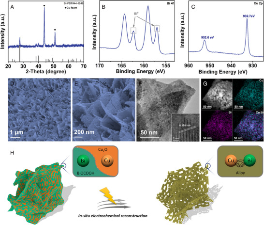
Characterization of eBiCu/CF: A, X‐ray diffraction (XRD) pattern, x‐ray photoelectron spectroscopy (XPS) spectra for B, Bi 4f and C, Cu 2p, D,E, SEM images, F, transmission electron microscopy (TEM) and G, energy‐dispersive x‐ray (EDX) elemental mapping images, and H, schematic illustration of in situ electrochemical reconstruction.
Second, after in situ electrochemical transformation, the obtained eBiCu/CF catalyst maintains the nanosheet array morphology with a three‐dimensional porous network structure (Figure 1D,E), which is beneficial for CO2 diffusion and rapid electrolyte penetration, potentially achieving excellent electrochemical CO2RR performance. Meanwhile, the transmission electron microscopy (TEM) image in Figure 1F indicates that many small pores are implanted on the surface of eBiCu nanosheets. According to the literature, the detachment of non‐metal atoms leads to the size contraction of the catalyst during electrochemical reconversion, thus producing abundant edge sites and porous morphology.[ 10 , 14 ] The lattice fringe in the high‐resolution TEM (HRTEM) image with a distance of 0.320 nm corresponds to the (012) crystal plane of Bi, thereby demonstrating the conversion of BiOCOOH to Bi (Figure 1F, inset). In addition, the energy‐dispersive x‐ray (EDX) image shows that Cu and Bi are uniformly distributed throughout the nanosheets, and the ratio of Cu and Bi is consistent with that in Bi‐O‐Cu/CF (Figure 1G and Figure S4). In a word, we have verified the successful preparation of eBiCu/CF through the above characterization, and its rough and porous ultrathin nanosheet array superstructure, as well as abundant edge sites (Figure 1H), are expected to achieve excellent electrocatalytic activity in subsequent CO2RR.[ 14 , 15 ]
2.2. Electrochemical performance of eBiCu/CF for CO2RR
The electrocatalytic CO2RR performance of eBiCu/CF was evaluated in the CO2‐saturated 0.5 M KHCO3 solution in an H‐type electrolytic cell. We first compared the electrochemical CO2RR performance of CF, Cu(OH)2/CF, and eBiCu/CF electrodes. Figure S5 shows the linear sweep voltammogram (LSV) curves in the CO2‐ and Ar‐saturated 0.5 M KHCO3 solution. Compared with the Ar‐saturated electrolyte, the current density significantly increased in the CO2‐saturated electrolyte, indicating that electrochemical CO2RR occurred on the eBiCu/CF electrode. To study the product distribution of electrochemical CO2RR, electrolysis was conducted at various potentials between −0.58 and −1.28 V for 1 h, and the gas and liquid products were quantitatively analyzed by gas chromatography (GC) and nuclear magnetic resonance (NMR) spectroscopy, respectively (Figure S6). The electrocatalytic results of eBiCu/CF indicate that formate is the only liquid product, with small amounts of H2, CO, and CH4 gas products, while CF and Cu(OH)2/CF mainly produce H2 (Figure S7). Further analysis shows that the j formate of eBiCu/CF is much larger than those of CF and Cu(OH)2/CF (Figure S8). It is found that the high selectivity of CO2‐to‐formate conversion strongly depends on the introduction of Bi on the electrode.
Furthermore, to decode the advantages of bimetallic synergy, we compared the electrochemical CO2RR performance of eBiCu/CF with that of the commercial Bi powder‐coated CF electrode, namely, cBi/CF. It is evident from Figure 2A that the eBiCu/CF electrode exhibits a higher current density and a smaller initial potential, indicating superior electrocatalytic performance and highlighting the structural benefits of the self‐supported array catalyst. We also conducted potentiostatic electrolysis to analyze the product distribution, and the i–t curves are shown in Figure S9. Concretely, the current densities of the cBi/CF electrode exhibit significant fluctuation and are much lower than those of eBiCu/CF. As shown in Figure 2B, the FEformate of the eBiCu/CF electrode exceeds 90% in the potential range of −0.78 to −1.18 V and reaches a maximum of 97.2% at −1.08 V, which is much higher than that of the cBi/CF electrode. In addition, the j formate of the electrocatalysts at different potentials was calculated (Figure 2C), and the results show that the j formate values of eBiCu/CF are much higher than those of cBi/CF, reaching 104.6 mA cm−2 at −1.28 V, further demonstrating the excellent activity of eBiCu/CF for electrocatalytic CO2RR to produce formate. The reaction kinetics of electrochemical CO2RR were analyzed by the Tafel slope. Figure 2D shows that the Tafel slope of eBiCu/CF (116.2 mV dec−1) is much smaller than that of the cBi/CF electrode (246.1 mV dec−1), indicating the excellent reaction kinetics of eBiCu/CF and facilitating the catalytic reaction. In addition, the long‐term stability test was carried out at −0.88 V (Figure 2E) and showed that the eBiCu/CF catalyst maintained stable current density and FE formate during 30 h of electrolysis, demonstrating its excellent electrochemical CO2RR stability compared with the state‐of‐the‐art counterparts (Table S1).
FIGURE 2.
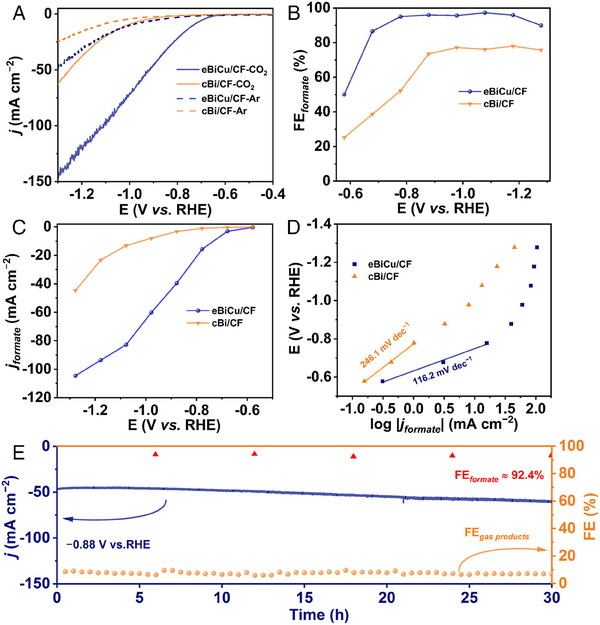
Electrochemical CO2RR performance of eBiCu/CF: A, Linear sweep voltammogram (LSV) curves, B, faradaic efficiency for formate (FEformate), C, j formate, D, Tafel plots, and E, long‐term stability.
The double‐layer capacitance (Cdl) can be used to estimate the electrochemical active surface area (ECSA) of the catalysts to further evaluate the inherent activity. Figure S10A,B shows the CV curves of the catalysts at different scan rates within the non‐faradaic potential range, and a Cdl of 24.6 mF cm−2 was obtained for the eBiCu/CF catalyst through further calculations, which is 35 times greater than that of the cBi/CF catalyst (0.7 mF cm−2; Figure S10C). This indicates that the self‐supported nanoarray superstructure of the eBiCu/CF catalyst endows it with abundant catalytic active sites. As shown in Figure S10D, the half‐circle diameter of eBiCu/CF is much smaller than that of cBi/CF, indicating a faster rate of charge transfer. Based on the electrochemical tests conducted, it can be concluded that the self‐supported eBiCu/CF nanoarray electrode exhibits significantly higher catalytic activity and selectivity when compared to the other contrast electrodes. This can be attributed to various factors including, (a) the 3D porous and open network of interconnected array superstructure, which promotes efficient charge and mass transfer; (b) the formation of electron‐rich Bi resulting from electronic transfer from Cu to Bi, which exhibits excellent intrinsic catalytic activity for electrochemical CO2RR to produce formate; (c) the self‐supported catalyst without the use of binders, featuring high conductivity and preventing adsorption sites and catalytic active sites from being covered; (d) the porous structure of the nanosheets, which can provide rich structural defects and edge sites that possess the higher intrinsic activity and contribute to improved electrocatalytic performance.
2.3. Characterizations and discussion of CuxNi1−x(OH)2/CF
According to the characteristic of anodic CHOR, we further developed CuxNi1−x(OH)2/CF electrocatalyst through hydrothermal treatment of Cu(OH)2/CF nanoarray. The XRD patterns in Figure 3A show that the diffraction peaks of Cu(OH)2 disappear while the diffraction peaks of Ni(OH)2 appear, suggesting the possible formation of Cu‐doped Ni(OH)2 phase. The electronic structure of CuxNi1−x(OH)2/CF was investigated by XPS in detail. As shown in Figure 3B, the peaks of Cu 2p1/2 at 954.4 and 952.3 eV correspond to Cu2+ and Cu0, respectively. The Cu 2p3/2 signal can also be fitted into two peaks at 934.5 and 932.6 eV, which are attributed to Cu2+ and Cu0, respectively.[ 16 ] The Ni 2p spectrum shows two main peaks of Ni 2p1/2 (856.0 eV) and Ni 2p3/2 (873.6 eV) for Ni2+ (Figure 3C). Meanwhile, the two peaks at 875.7 and 858.6 eV belonging to Ni3+ might be caused by partial surface oxidation, which has been widely observed in other transition metal‐based compounds.[ 17 ] In addition, the O 1s spectrum also shows the existence of three kinds of oxygen in the sample (Figure S11), indicating the integration of bimetallic hydroxides. The SEM images reveal that the morphology of the nanowire array is maintained after hydrothermal casting, while tightly stacked and connected ultrathin nanosheets are in situ formed on the surface, making the surface of the nanowires rougher and further increasing the surface area of CuxNi1−x(OH)2/CF (Figure 3D,E). The TEM images also confirm the nanosheet‐on‐nanowire morphology of CuxNi1−x(OH)2/CF, and the ultrathin nanostructure of the nanosheets is identified (Figure 3F). Furthermore, the HRTEM image displays a crystal lattice pattern of 0.463 nm, corresponding to the (001) crystal plane of Ni(OH)2 (0.461 nm), and the slight deviation may be due to the lattice distortion caused by Cu doping in the Ni(OH)2 lattice (Figure 3F, inset). The EDX mapping images show a uniform distribution of Ni, Cu, and O throughout the entire nanowire, further indicating the uniform growth of the nanosheet‐wrapped nanowire (Figure 3G). In particular, Figure S12 shows that the elemental content ratio of (Ni+Cu) to O is close to 1:2, which is consistent with the XRD result, proving the successful construction of the designed electrocatalyst.
FIGURE 3.
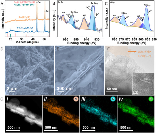
Characterizations of CuxNi1−x(OH)2/CF: A, X‐ray diffraction (XRD) pattern, x‐ray photoelectron spectroscopy (XPS) spectra for B, Cu 2p and C, Ni 2p, D,E, SEM, F, transmission electron microscopy (TEM), and G, energy‐dispersive x‐ray (EDX) elemental mapping images (note: for (F), pseudo‐color is used to highlight the ultrathin structure of the nanosheet).
2.4. Electrochemical performance of CuxNi1−x(OH)2/CF for CHOR
The electrocatalytic performance of CuxNi1−x(OH)2/CF for CHOR was evaluated in a standard three‐electrode system. Figure 4A shows the LSV curves of the prepared electrode in 1.0 M NaOH solution with or without 0.1 M cyclohexanone added (90% iR compensation correction). Notably, the electrochemical CHOR performance of CuxNi1−x(OH)2/CF is superior to that of Cu(OH)2/CF. The initial potential of CuxNi1−x(OH)2/CF is significantly lowered after the addition of 0.1 M cyclohexanone. At the same time, the Tafel slope is significantly reduced upon the addition of cyclohexanone, indicating that CHOR has more favorable thermodynamics and faster catalytic reaction kinetics compared to OER (Figure 4B). Subsequently, the products during CHOR were quantitatively analyzed using potentiostatic electrolysis, and it can be seen from the i–t curves that the current densities of CuxNi1−x(OH)2/CF are significantly higher than those of Cu(OH)2/CF at the same potentials (Figure S13). The 1H NMR spectrum confirms the formation of adipate (Figure 4C). As shown in Figure 4D, FEadipate of CuxNi1−x(OH)2/CF is much higher than those of Cu(OH)2/CF, suggesting the significant advantage of a bimetallic array in electrochemical CHOR. Notably, the FEadipate of CuxNi1−x(OH)2/CF is close to 100% at the potentials below 1.52 V. However, at the higher potentials, the FEadipate gradually decreases, which is attributed to the competitive OER reaction. At the same time, the ECSAs of CuxNi1−x(OH)2/CF and Cu(OH)2/CF were measured, and the results show that the ECSA of CuxNi1−x(OH)2/CF is much larger than that of Cu(OH)2/CF, indicating that the hierarchical surface of CuxNi1−x(OH)2/CF can provide more accessible active sites (Figure S14A–C). Further electrochemical impedance spectroscopy (EIS) test shows that CuxNi1−x(OH)2/CF has superior charge transfer kinetics (Figure S14D). In addition, the long‐term stability was executed, and the result is shown in Figure 4E. During nearly 50 h of electrolysis, CuxNi1−x(OH)2/CF was able to maintain a stable current density while achieving a high FEadipate of 93.1%, superior to the reported performances (Table S2). In conclusion, through bimetallic construction, the designed CuxNi1−x(OH)2/CF has excellent performance for the oxidation of cyclohexanone to adipate.
FIGURE 4.
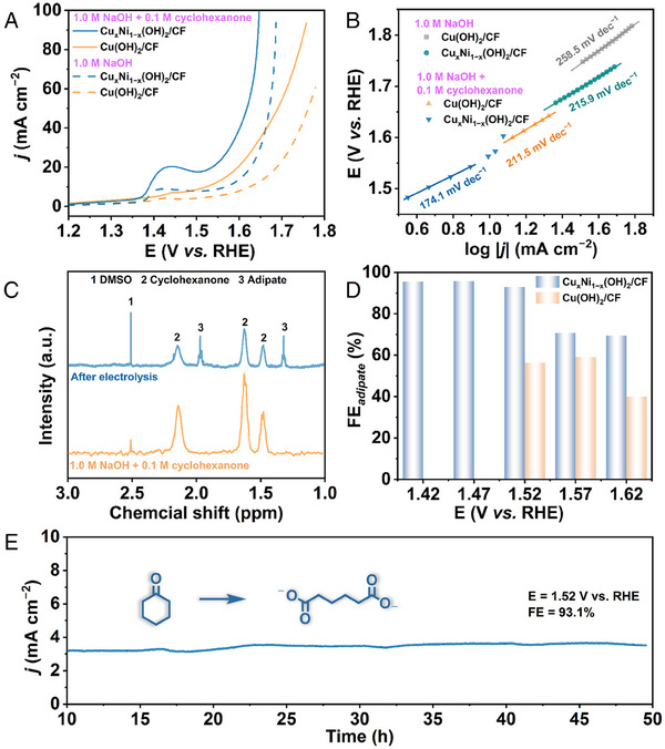
Electrochemical cyclohexanone oxidation reaction (CHOR) performance of CuxNi1−x(OH)2/CF: A, Linear sweep voltammogram (LSV) curves, B, Tafel plots, C, 1H NMR spectra, D, faradaic efficiency of adipate (FEadipate), and E, long‐term stability.
2.5. Integration of CO2RR and CHOR for coupling electrosynthesis
Given the excellent electrochemical performance of eBiCu/CF for CO2RR and CuxNi1−x(OH)2/CF for CHOR, a bipolar membrane (BPM) separated CO2RR//CHOR full cell was constructed (Figure 5A). The catholyte was CO2‐saturated 0.5 M KHCO3 aqueous solution, while the anolyte was 1.0 M NaOH solution with or without the addition of 0.1 M cyclohexanone. When the anode contained 0.1 M cyclohexanone, the electrolysis cell only required 3.0 V to achieve a current density of 20 mA cm−2, which is 522 mV lower than the potential required without cyclohexanone (Figure 5B). At the same current density, the electrolysis voltage of the CO2RR//CHOR electrolysis cell was much lower than that of the CO2RR//OER cell, highlighting the significant thermodynamic advantage of CHOR over OER (Figure 5C). Further investigation of the products at the anode and cathode was conducted using potentiostatic electrolysis, and the i–t curves are shown in Figure S15, demonstrating good stability during the electrolysis process. More importantly, Figure 5D shows that both the anode and cathode maintained high FEs in a wide potential range, highlighting the vista of coupling electrosynthesis. Moreover, the XRD and SEM results of the electrolyzed samples also confirm their exceptional structure stability (Figures S16 and S17). The above results multidimensionally indicate that the CO2RR//CHOR electrolysis system is feasible for the coupling electrosynthesis of formate and adipate.
FIGURE 5.
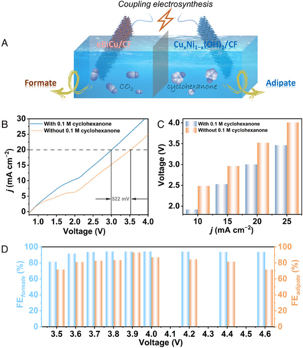
Two‐electrode electrolyzer for coupling electrosynthesis of formate and adipate using eBiCu/CF as the cathodic catalyst and CuxNi1−x(OH)2/CF as the anodic catalyst: A, schematic illustration, B, linear sweep voltammogram (LSV) curves, C, potentials at different current densities, and D, faradaic efficiencies (FEs).
3. CONCLUSIONS
This work systematically demonstrated the use of Cu(OH)2 nanowire arrays as a processable material platform to construct self‐supported bimetallic array superstructures with multiple structural advantages for highly efficient coupling electrosynthesis. By virtue of the self‐supported nanosheet array superstructure with abundant accessible active sites, high conductivity, and fast mass transport, the eBiCu/CF cathodic catalyst for electrochemical CO2‐to‐formate conversion can achieve over 90% FEformate in the wide potential range of 400 mV, and j formate can reach up to 104.6 mA cm−2 at −1.28 V. Meanwhile, using the nanosheet‐on‐nanowire array superstructured CuxNi1−x(OH)2/CF as the anode for adipate electrosynthesis, nearly 100% FEadipate was obtained, and the current densities are much higher than those of OER. More reliably, the CO2RR//CHOR electrolyzer requires a voltage of only 3.0 V to achieve the current density of 20 mA cm−2, which is 522 mV lower than that required by CO2RR//OER, and the maximal FEformate and FEadipate can reach up to 94.2% and 93.1%, respectively. The coupling electrolysis system can significantly improve the economic benefit of CO2 electrolysis and simultaneously achieve the high‐efficiency electrosynthesis of adipate, providing valuable references for the green synthesis of other high‐value‐added chemical products.
4. EXPERIMENTAL SECTION
4.1. Preparation of catalysts
4.1.1. Preparation of Cu(OH)2/CF
Cu(OH)2/CF was synthesized according to our previous work.[ 18 ] The obtained mazarine Cu(OH)2/CF was stored in a vacuum desiccator at room temperature.
4.1.2. Preparation of Bi‐O‐Cu/CF
1.0 mmol of Bi(NO3)3·5H2O was dissolved in a solution consisting of 12 mL of H2O, 3 mL of glycerol, and 5 mL of N,N‐dimethyl formamide (DMF) through vigorous stirring for 30 min. The mixed solution was then transferred to a 50 mL Teflon‐lined autoclave, where a piece of Cu(OH)2/CF with a size of 2 × 2.5 cm2 was added, sealed, and heated at 120°C for 12 h. After the reaction, the obtained Bi‐O‐Cu/CF was washed with deionized water and ethanol several times and dried in a vacuum at 60°C.
4.1.3. Preparation of eBiCu/CF
eBiCu/CF was prepared by in situ electrochemical conversion of Bi‐O‐Cu/CF in a three‐electrode system consisting of a CO2‐saturated 0.5 M KHCO3 solution. Concretely, 100 cycles of cyclic voltammetry (CV) experiments were carried out at a scanning rate of 100 mV s−1 within the potential range of −0.8 to −1.8 V (vs. Ag/AgCl). The as‐obtained electrode was then taken out from the electrolyte, rinsed with deionized water, and directly used as a working electrode for subsequent experiments.
4.1.4. Preparation of cBi/CF
1.0 mg of commercial Bi powder was dispersed in a 100 μL mixed solution consisting of H2O (70 μL), isopropanol (20 μL), and Nafion (10 μL) with ultrasonic treatment for 2 h. Then, the above ink was dropped onto the CF with the size of 1.0 × 1.0 cm2 and dried naturally at room temperature.
4.1.5. Preparation of CuxNi1−x(OH)2/CF
0.436 g of Ni(NO3)2·6H2O, 0.154 g of NH4F, and 0.997 g of urea were dissolved in 40 mL of H2O and stirred for 30 min to get a homogeneous solution. The mixed solution was then transferred to a 100‐mL Teflon‐lined autoclave, where a piece of Cu(OH)2/CF with a size of 2 × 2.5 cm2 was added, sealed, and heated at 100°C for 10 h. After the reaction, the obtained CuxNi1−x(OH)2/CF was taken out from the solution, washed with deionized water and ethanol several times, and dried in a vacuum at 60°C.
4.2. Electrochemical measurements
Other experimental details are provided in the Supporting Information.
AUTHOR CONTRIBUTIONS
Dong‐Dong Ma and Qi‐Long Zhu conceived the research and designed the experiments. Li Liu and Yingchun He carried out the synthesis, material characterizations, and electrochemical measurements. Li Liu, Yingchun He, Qing Li, Changsheng Cao, Dong‐Dong Ma, Xin‐Tao Wu, and Qi‐Long Zhu analyzed and discussed the data. Li Liu, Yingchun He, Dong‐Dong Ma, and Qi‐Long Zhu drafted the manuscript. All authors discussed and revised the manuscript.
CONFLICT OF INTEREST STATEMENT
The authors declare no conflicts of interest.
Supporting information
Supporting Information
ACKNOWLEDGEMENTS
The authors are grateful to the National Natural Science Foundation of China (22105203, 22175174, 52332007 and 22375203), the National Key Research and Development Program of China (2021YFA1500402), the Natural Science Foundation of Fujian Province (2021J06033 and 2022L3092), and the China Postdoctoral Science Foundation (2021TQ0332 and 2021M703215).
Liu L., He Y., Li Q., Cao C., Huang M., Ma D.‐D., Wu X.‐T., Zhu Q.‐L., Exploration 2024, 4, 20230043. 10.1002/EXP.20230043
Li Liu and Yingchun He contributed equally to this work.
Contributor Information
Dong‐Dong Ma, Email: madong@fjirsm.ac.cn.
Qi‐Long Zhu, Email: qlzhu@fjirsm.ac.cn.
DATA AVAILABILITY STATEMENT
All data of this work are present in the article and Supporting Information. The other data that support the findings of this work are available from the corresponding author upon reasonable request.
REFERENCES
- 1.a) Ye Q., Yuan E., Shen J., Ye M., Xu Q., Hu X., Shu Y., Pang H., Adv. Sci. 2023, 10, 2304149; [DOI] [PMC free article] [PubMed] [Google Scholar]; b) Qiu Z., Li Y., Gao Y., Meng Z., Sun Y., Bai Y., Suen N.‐T., Chen H.‐C., Pi Y., Pang H., Angew. Chem. Int. Ed. 2023, 62, e202306881; [DOI] [PubMed] [Google Scholar]; c) Sun Y., Ding S., Xia B., Duan J., Antonietti M., Chen S., Angew. Chem. Int. Ed. 2022, 61, e202115198; [DOI] [PubMed] [Google Scholar]; d) Ma D.‐D., Han S.‐G., Zhou S.‐H., Wei W.‐B., Li X., Chen B., Wu X.‐T., Zhu Q.‐L., CCS Chem. 2023, 5, 1827. [Google Scholar]
- 2.a) Han S.‐G., Ma D.‐D., Zhou S.‐H., Zhang K., Wei W.‐B., Du Y., Wu X.‐T., Xu Q., Zou R., Zhu Q.‐L., Appl. Catal., B 2021, 283, 119591; [Google Scholar]; b) Sheng Y., Guo Y., Yu H., Deng K., Wang Z., Li X., Wang H., Wang L., Xu Y., Small 2023, 19, e2207305; [DOI] [PubMed] [Google Scholar]; c) Cao C., Ma D.‐D., Jia J., Xu Q., Wu X.‐T., Zhu Q.‐L., Adv. Mater. 2021, 33, e2008631; [DOI] [PubMed] [Google Scholar]; d) Li Y.‐H., Zhao S.‐N., Zang S.‐Q., Exploration 2023, 3, 20220005; [DOI] [PMC free article] [PubMed] [Google Scholar]; e) Ding Y., Wang C., Zheng R., Maitra S., Zhang G., Barakat T., Roy S., Su B.‐L., Chen L.‐H., EnergyChem 2022, 4, 100081. [Google Scholar]
- 3.a) Liang Y., Wang J., Liu D., Wu L., Li T., Yan S., Fan Q., Zhu K., Zou Z., J. Mater. Chem. A 2021, 9, 21785; [Google Scholar]; b) Wang C., Jin L., Shang H., Xu H., Shiraishi Y., Du Y., Chin. Chem. Lett. 2021, 32, 2108; [Google Scholar]; c) Zhang Z., Wang C., Ma X., Liu F., Xiao H., Zhang J., Lin Z., Hao Z., Small 2021, 17, e2103785. [DOI] [PubMed] [Google Scholar]
- 4.a) Xu Z., Peng C., Zheng G., Chemistry 2023, 29, e202203147; [DOI] [PubMed] [Google Scholar]; b) Arshad F., Haq T. u., Hussain I., Sher F., ACS Appl. Energy Mater. 2021, 4, 8685; [Google Scholar]; c) Pi Y., Qiu Z., Sun Y., Ishii H., Liao Y.‐F., Zhang X., Chen H.‐Y., Pang H., Adv. Sci. 2023, 10, 2206096; [DOI] [PMC free article] [PubMed] [Google Scholar]; d) Gong M., Cao C., Zhu Q.‐L., EnergyChem 2023, 5, 100111. [Google Scholar]
- 5.a) Yang J., Liu J., Neumann H., Franke R., Jackstell R., Beller M., Science 2019, 366, 1514; [DOI] [PubMed] [Google Scholar]; b) Kruyer N. S., Peralta‐Yahya P., Curr. Opin. Biotechnol. 2017, 45, 136. [DOI] [PubMed] [Google Scholar]
- 6.a) Schaub T., Science 2019, 366, 1447; [DOI] [PubMed] [Google Scholar]; b) Schneider C., Leischner T., Ryabchuk P., Jackstell R., Junge K., Beller M., CCS Chem. 2021, 3, 512. [Google Scholar]
- 7. Rios J., Lebeau J., Yang T., Li S., Lynch M. D., Green Chem. 2021, 23, 3172. [Google Scholar]
- 8.a) Li Z., Li X., Zhou H., Xu Y., Xu S. M., Ren Y., Yan Y., Yang J., Ji K., Li L., Xu M., Shao M., Kong X., Sun X., Duan H., Nat. Commun. 2022, 13, 5009; [DOI] [PMC free article] [PubMed] [Google Scholar]; b) Wang R., Kang Y., Wu J., Jiang T., Wang Y., Gu L., Li Y., Yang X., Liu Z., Gong M., Angew. Chem. Int. Ed. 2022, 61, e202214977. [DOI] [PubMed] [Google Scholar]
- 9.a) Yang Y., Meng H., Yan S., Zhu H., Ma W., Wang C., Ma F., Hu Z., J. Alloys Compd. 2021, 874, 159874; [Google Scholar]; b) Zhang Y., Qi L., Nanoscale 2022, 14, 12196; [DOI] [PubMed] [Google Scholar]; c) Hou J., Wu Y., Zhang B., Cao S., Li Z., Sun L., Adv. Funct. Mater. 2019, 29, 1808367; [Google Scholar]; d) Zhao H., Lei Y., Adv. Energy Mater. 2020, 10, 2001460; [Google Scholar]; e) Sun Y., Xu S., Ortíz‐Ledón C. A., Zhu J., Chen S., Duan J., Exploration 2021, 1, 20210021. [DOI] [PMC free article] [PubMed] [Google Scholar]
- 10.a) Fan J., Zhao X., Mao X., Xu J., Han N., Yang H., Pan B., Li Y., Wang L., Li Y., Adv. Mater. 2021, 33, e2100910; [DOI] [PubMed] [Google Scholar]; b) Wang M., Liu S., Chen B., Huang M. J., Peng C., Chem. Eng. J. 2023, 451, 139056; [Google Scholar]; c) Wang Y., Li Y., Liu J., Dong C., Xiao C., Cheng L., Jiang H., Jiang H., Li C., Angew. Chem. Int. Ed. 2021, 60, 7681; [DOI] [PubMed] [Google Scholar]; d) Yang C., Hu Y., Li S., Huang Q., Peng J., ACS Appl. Mater. Interfaces 2023, 15, 6942; [DOI] [PubMed] [Google Scholar]; e) Zhang M., Wei W., Zhou S., Ma D.‐D., Cao A., Wu X.‐T., Zhu Q.‐L., Energy Environ. Sci. 2021, 14, 4998. [Google Scholar]
- 11. Wan Y., Zhou H., Zheng M., Huang Z. H., Kang F., Li J., Lv R., Adv. Funct. Mater. 2021, 31, 2100300. [Google Scholar]
- 12. Jiang P., Prendergast D., Borondics F., Porsgaard S., Giovanetti L., Pach E., Newberg J., Bluhm H., Besenbacher F., Salmeron M., J. Chem. Phys. 2013, 138, 024704. [DOI] [PubMed] [Google Scholar]
- 13. Li Z., Sun B., Xiao D., Wang Z., Liu Y., Zheng Z., Wang P., Dai Y., Cheng H., Huang B., Angew. Chem. Int. Ed. 2023, 62, e202217569. [DOI] [PubMed] [Google Scholar]
- 14. Zeng G., He Y., Ma D.‐D., Luo S., Zhou S., Cao C., Li X., Wu X.‐T., Liao H.‐G., Zhu Q.‐L., Adv. Funct. Mater. 2022, 32, 2201125. [Google Scholar]
- 15. He Y.‐C., Ma D.‐D., Zhou S.‐H., Zhang M., Tian J.‐J., Zhu Q.‐L., Small 2022, 18, e2105246. [DOI] [PubMed] [Google Scholar]
- 16.a) Chen F., Chen C., Hu Q., Xiang B., Song T., Zou X., Li W., Xiong B., Deng M., Chem. Eng. J. 2020, 401, 126145; [Google Scholar]; b) Jiang J., Liu X., Han J., Hu K., Chen J. S., Processes 2021, 9, 680. [Google Scholar]
- 17. Huang C., Hu Y., Jiang S., Chen H., Electrochim. Acta 2019, 325, 134936. [Google Scholar]
- 18. Liu L., He Y., Ma D. D., Wu X. T., Zhu Q. L., J. Colloid Interface Sci. 2023, 640, 423. [DOI] [PubMed] [Google Scholar]
Associated Data
This section collects any data citations, data availability statements, or supplementary materials included in this article.
Supplementary Materials
Supporting Information
Data Availability Statement
All data of this work are present in the article and Supporting Information. The other data that support the findings of this work are available from the corresponding author upon reasonable request.


