

Abstract

Geological modeling is a three-dimensional (3D) representation of comprehensive geological research results in oil fields. In this paper, first, the comprehensive geological research results were fully applied to establish geological models such as matrix, reservoir, and fractures in the study area. Second, in response to the geological characteristics of carbonate fractured and vuggy reservoirs, various data are integrated. Finally, by collecting and organizing various basic data mentioned above, a refined geological model of the oil reservoir in the study area is established. Results show that (a) Due to the complexity of the distribution of cracks and pores, the presence of these unrelated grids also affects the observation of target cracks and pores. (b) There may be multiple adjacent nodes in the initial access node. The strategy of depth-first traversal is to first access the first adjacent node. (c) There is a significant difference between the connected units extracted solely from static data and the connected units reextracted after fine-tuning the crack position considering dynamic data
1. Introduction
Geological modeling is a three-dimensional (3D) representation of comprehensive geological research results in oil fields.1−3 It is a high-level summary of the internal characteristics, external morphology, scale, reservoir characteristics, fluid properties, and distribution patterns of oil reservoirs.4−7 It can intuitively and accurately analyze and study the spatial distribution of geological body morphology, configuration relationships, and reservoir properties.8−12 From the perspective of changes in technical means and the degree of application of data, the development of seismic structural interpretation has roughly gone through four stages, namely, initial stage, development stage, continued development stage, and major development stage.13−16
Li et al.17 classified the types of fault solution reservoirs and found that the main control factors of fault solution reservoirs are fault size, distance from faults, direction of in situ stress, and fluid alteration. Tian et al.18 used waveform indication inversion algorithms to analyze geophysical data and combined seismic impedance data to characterize reservoir geometry. Zhao et al.19 analyzed the development and fault control laws of high and low internal reservoirs of Ordovician carbonate rocks in the Tabei ancient uplift and found that there are large fractured cave-type reservoirs developed in the Tabei ancient uplift, with cave-type reservoirs as the main reservoirs. Hui et al.20 established an unconventional crack model and analyzed the propagation behavior of cracks. Marinković et al.21 conducted a composite hydrogeothermal investigation of the post-Neotethys Late Paleogene Neogene crustal core complex in the Kopaonik Mountains of the southwestern Serbian Plateau. The fractured carbonate reservoirs in Tahe Oilfield are different from conventional porous sandstone reservoirs and other karst carbonate reservoirs.22−24 The main storage space of oil reservoirs is mainly composed of cracks and caves formed by structural deformation and collapse, as well as pores and caves formed by karst processes.25−28 The large karst caves are the most important storage space, and cracks are the main connecting channels.29−33 Due to the different types of karst caves and cracks of different scales, their morphology and scale are different, making it difficult to establish a unified geological model using a single method.34−38 Therefore, different modeling methods are used to establish discrete models for different constituent elements.37−38,39 Then, the discrete models were integrated into a wpore, establishing a three-dimensional distribution model of the fractured and vuggy reservoir.45−56
In this paper, first, based on the systematic collection and organization of various basic data, the comprehensive geological research results were fully applied to establish geological models such as matrix, reservoir, and fractures in the study area, providing a more systematic, realistic, and accurate three-dimensional geological model for reservoir numerical simulation. Second, in response to the geological characteristics of carbonate fractured and vuggy reservoirs, various data are integrated, including rock outcrop data, seismic interpretation data, logging data, core data, well testing data, production performance data, etc. Finally, by systematically collecting and organizing various basic data mentioned above, a refined geological model of the oil reservoir in the study area is established.
2. T-12518 Strip 3D Geological Modeling
2.1. Structural Model
Based on the T74 time domain structural plane of T-12518 block, a depth domain structural plane of the T74 layer was established through time depth transformation. Based on the top surface of the depth domain, the structure was corrected using drilling layering data. Take the corrected top surface down 400 m as the bottom surface of the model.
2.2. Fault Model
Based on the scattered reflectance data volume, the data was processed and tracked according to the scattered reflectance characteristics, and a fault model of T-12518 was established, including 2 Type I faults and 1 Type II and III fault each.
2.3. Grid Model
The modeling range is T-12518 strips, with an area of 125 km2. Take the top surface of the T74 layer as the top surface of the model, and take 400 m below the T74 layer as the bottom boundary of the model. The grid accuracy is relatively high, with a flat grid accuracy of 15 m × 15 m and a vertical grid accuracy of 5 m. Among them, there are 420 grids in the I direction, 1335 grids in the J direction, and 80 grids in the K direction, resulting in a total of 44.85 million grids.
2.4. Fracture Model
On the basis of scattered reflection 3D seismic data volume, apply Tracy’s patented technology for crack reconstruction. Extract crack strength and direction from different boundary detection attribute volumes. Then, convert the interpretation results into crack fragments, as shown in Figure 1.
Figure 1.

Process of reconstructing discrete crack grids based on messy detection data volume.
There is a good correspondence between chaotic reflection data volume and fracture. Extract medium- and small-scale cracks based on scattered reflections. The extraction results reflect the control law of fractures on cracks. There are complex small-scale cracks developed at the top of the fracture zone, as shown in Figure 2.
Figure 2.

Crack model established after reconstruction. (a) Medium- and small-scale cracks model; (b) multiscale fracture model.
2.5. Reservoir Model
A reservoir facies model for the study area was established based on the range of fractured and vuggy reservoirs interpreted by earthquakes. Cave-type reservoir: According to the results of seismic interpretation, the threshold value of cave-type reservoir is 3.9, and a cave-type reservoir model has been established. Fractured and porous reservoirs: Based on the type of fractured and porous reservoir encountered during single well drilling, the actual drilling calibration of the fractured and porous reservoir is carried out to ensure that there are mostly abnormal reflections near the fractured and porous reservoir wells, and the threshold value is determined to be 7. Note that the threshold value refers to a value where there is a turning point in the pattern of data changes.
The relationship of the five models in spatial-temporal domain is shown in Figure 3.
Figure 3.

3D geological modeling flowchart.
3. Multiscale Discrete Crack Modeling
Fractured reservoirs are an important type of oil and gas reservoirs. In carbonate fractured and vuggy reservoirs, the development of fractures plays an important role in reservoir connectivity and reservoir performance. The description of reservoir fractures is difficult to quantify due to its strong heterogeneity, and difficulty in integrating information from different scales and sources. Although fractured reservoirs face so many challenges, with the development of oil reservoirs, the amount of data collected and the difficulty of extraction have increased, and the accuracy requirements for reservoir characterization have become increasingly high. It is necessary to establish a high-precision geological model that integrates multisource fracture interpretation data for static geological analysis, reserve evaluation, and well location deployment, and to guide the formulation of oil and gas reservoir development plans.
The discrete crack model provides a complete and explicit description of all cracks based on their actual size and distribution pattern. Due to its precise description and accurate simulation results, it is widely respected. However, due to the limitations of reservoir measurement data, description methods, and computational speed, the development of discrete fracture models has been slow for a long time. Since the beginning of the 21st century, advanced measurement methods and fracture description techniques, as well as rapidly increasing computer processing speed, have made significant progress in fine modeling and numerical simulation of discrete fractures, and have also made it possible to apply them to actual reservoir scales.
In the discrete crack modeling stage of this study, T-12518 bands were selected for discrete crack modeling.
3.1. Basic Principles of Discrete Crack Model
One notable technological innovation in discrete fracture modeling methods is the discrete fracture reservoir simulation method based on connected tables proposed by Karimi-Fard et al.57 from Stanford University in the United States in 2004. This method adopts the finite volume method and characterizes the transmission rate between unstructured grids in the form of connected tables. This method has been successfully applied to single-phase and multiphase flow simulations in two-dimensional (2D) and three-dimensional oil reservoirs. The main work of discrete crack modeling is also based on the extension and application of Karimi-Fard et al.’s57 technology. In this method, the fractured reservoir system is presented through high-resolution unstructured grids. The reason for using unstructured grids to characterize fractured reservoirs is that compared to structured grids such as orthogonal grids and corner grids, unstructured grids are more flexible and can adapt to fracture systems with very complex geometric shapes. In the past, when describing fractured reservoirs, the shape of the fractures was usually represented by an ellipsoid. In order to simplify the model and the complexity of mesh generation, the crack is simplified as a plane with thickness (in a two-dimensional model, it is a line segment with width). The thickness of a plane or the width of a line segment are attributes of cracks. When generating unstructured grids, there is no need to consider it, only when conducting subsequent calculations such as crack permeability, grid volume, and conductivity. It should be noted that in a long crack, there may be different permeabilities due to the varying degrees of opening in each part of the crack. This treatment assumes that the fluid must flow along the plate in the crack. This is reasonable under actual crack size and opening conditions. However, it should be noted that due to the use of line segments to represent cracks in the geometric mesh and the consideration of crack width in the calculation model, it can cause the total volume to be nonconserved. When there are many cracks, this error cannot be ignored. The method of processing is to make volume corrections to the matrix mesh adjacent to the crack, that is, when calculating the volume of the matrix mesh (only the information on the center point and intersection surface is used to calculate the conductivity, and no correction is needed), half of the volume of the adjacent crack mesh should be subtracted from it. If an unstructured grid model is used, only about 400 grids are needed to provide a highly accurate description of the model. If the crack geometry is “dimensionally reduced”, the number of grids can be further reduced to around 350. By assigning different widths to crack segments, the complexity of the unstructured mesh system is greatly reduced while preserving the characteristics of the original model. In practical applications, discrete crack models can be described using control volumes of any suitable shape, as shown in Table 1.
Table 1. Comparison of Two-Dimensional and Three-Dimensional Morphology of Matrix and Cracks.

After processing the unstructured grid to characterize the discrete crack system, the next step is to calculate the conductivity of the grid and prepare a conductivity connectivity table for numerical simulation. Overall, traditional methods and discrete crack methods each have their own characteristics and advantages and disadvantages. Generally speaking, for reservoirs with highly developed fractures, considering the cost of fracture description and calculation, the dual pore model is a more practical and effective method. However, for models with relatively few fractures or certain fractures dominating the entire reservoir flow, the discrete fracture model is undoubtedly a more direct and accurate choice. Of course, with the progress of science and technology, the description of reservoirs will become more precise and the calculation speed will also become faster, so the advantages of the discrete fracture method will also become more significant, as shown in Figure 4.
Figure 4.

Applicability of the dual pore model and the discrete crack model.
3.2. Embedded Discrete Crack Modeling
The existing discrete crack numerical models are all based on matched grids, which use cracks as internal boundaries and use them as constraint surfaces for mesh generation. Due to the complexity of the geometric morphology of cracks, unstructured mesh technology is required, and its meshing process is very complex and cumbersome, especially when the distance or angle between cracks is small, which often leads to computational difficulties due to poor mesh division quality. The embedded discrete crack model directly embeds the crack network into the bedrock structured grid system, avoiding the complex unstructured grid generation process mentioned above. Although it is necessary to calculate the geometric information between cracks and meshes, compared to the complex unstructured mesh generation process, its computational complexity is greatly reduced, which can improve computational efficiency.
The embedded discrete crack model directly embeds cracks into the existing structured grid system. Due to the use of analytical methods to calculate the fluid exchange between cracks and the matrix, the accuracy of the embedded discrete crack model is to some extent inferior to that of the discrete crack model that characterizes all cracks as they are. However, due to the fact that the embedded discrete crack model considers the true distribution and geometric form of discrete cracks, its accuracy has been significantly improved compared to idealized equivalent models such as dual medium models.
When embedding discrete cracks in this model, only the conductivity between the cracks and the grid needs to be calculated. Compared to the complex unstructured mesh generation process, the modeling complexity is greatly reduced. In addition, the embedded discrete crack model can be compatible with all numerical simulation software. Therefore, considering the ease of use, stability, accuracy, and efficiency of modeling, the embedded discrete crack model is an excellent equilibrium model in all aspects, as shown in Figure 5.
Figure 5.

Comparison between discrete crack models and embedded discrete crack models.
In addition, existing discrete fracture numerical models use unstructured grids and require specialized reservoir numerical simulation software for simulation calculations. Moreover, for crack systems with complex geometric shapes, the process of unstructured mesh generation is relatively cumbersome. The embedded discrete crack model avoids this problem and can even be simulated using emulators such as Eclipse.
This study provides a new embedded discrete crack conduction relationship characterization method. The specific steps include:
Step 1: Define the original mesh model, including corner mesh geometric information, porosity, permeability, and other data;
Step 2: Define the original discrete crack geometry data, including crack polygon geometry information, crack opening, conductivity coefficient, and other data;
Step 3: Calculate the polygons intercepted by the background matrix mesh when embedding each discrete crack polygon into the background matrix mesh;
Step 4: Traverse each background matrix grid, find all cracks F in any background matrix grid I, and group F according to the connectivity relationship. If there are n sets of connected cracks, divide f into f1, f2,···, fn;
Step 5: Calculate the conductivity of matrix grid I, crack fi, and crack fi crack fj, respectively, and generate a numerical simulation model.
In this study, the fault extraction results of T-12518 belts were embedded into the geological model, forming an embedded discrete fracture model. Directly embed large-scale cracks in the work area into the original high-resolution corner grid model (matrix grid 15 m × 15 m × 5 m). After embedding the cracks, the original corner grid structure is not changed, and only a few crack patch grids are added. The embedded grid is shown in Figure 6. The number of matrix grids is 6.87 million, and the number of crack grids is 280,000. But most of the grids are still invalid, with a total of 970,000 effective grids in the model. There are still many grids in the entire model, and the overall simulation speed is slow, as shown in Figure 6.
Figure 6.
Embedded discrete crack model is formed by embedding the large crack into the T-12518 southern zone model.
4. Results and Discussion
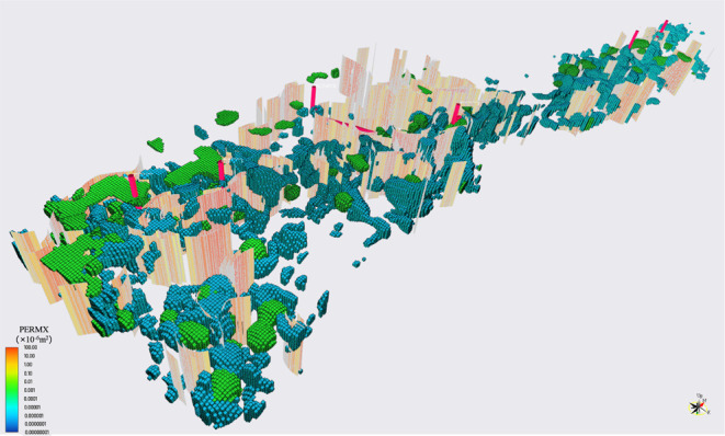
As mentioned in the previous section, the directly established embedded fracture reservoir model has a large number of grids, and due to its precise characterization of the flow in the fractures, it affects the convergence of the model. Therefore, this EDFM model takes a long time to calculate in a single operation and is difficult to carry out a large number of historical fitting adjustments, as shown in Figure 7.
Figure 7.
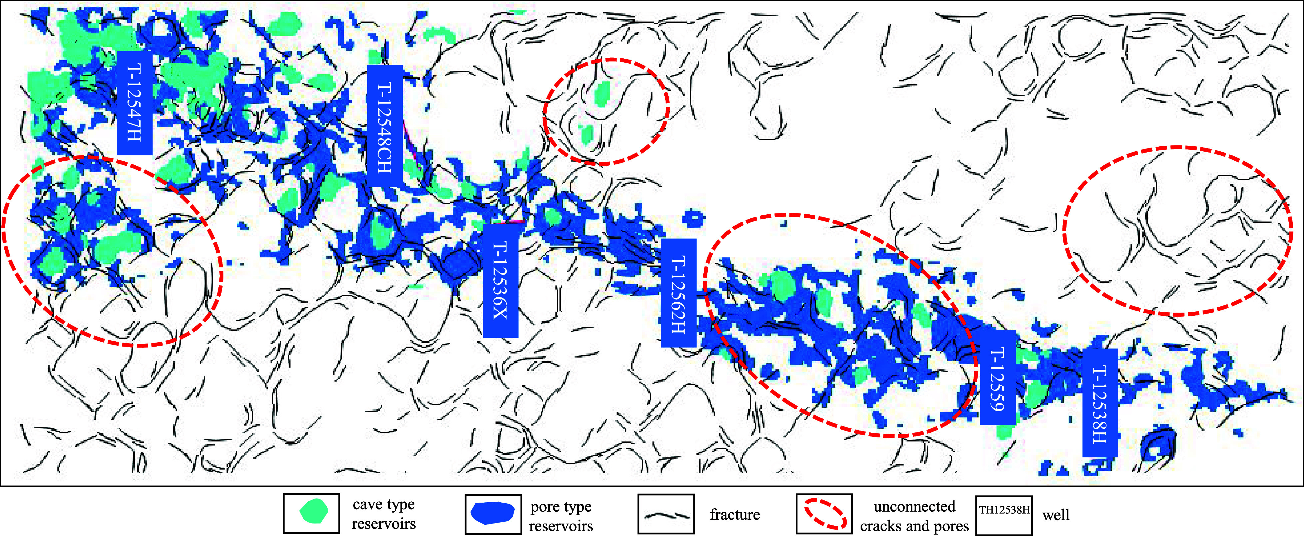
Directly established model contains a large number of unconnected cracks and pores.
However, considering that a large number of fractures and caves are not connected to the well, these fracture and cave units will not exchange biomass and pressure with the well. Whether to consider this has no impact on the calculation results (the area within the red dashed line in the above figure is the area that is not connected to the well). But in fact, these grids still participate in computing, resulting in a significant waste of computing resources. At the same time, due to the complexity of the distribution of cracks and pores, the presence of these unrelated grids also affects the observation of target cracks and pores. In addition, due to the complexity of fractured and vuggy reservoirs, the connectivity relationships between different wells are different. It is not necessary to analyze wells that are not connected to each other using the same model and should be studied separately.
Based on the above three considerations, only the fracture and cavity units connected to the well should be extracted as the research object. This can greatly reduce the number of grids and save computational resources. Second, it is convenient to observe the flow conditions observed in the crevices. However, the target oil reservoir has a large number of fractures and complex connectivity relationships, and relying on manual delineation of the connectivity range has poor accuracy and unreliable results.
This study proposes for the first time a connected unit extraction method based on adjacency table. The adjacency relationship table between grids formed by embedded discrete crack modeling is used to determine the connectivity between grids. Greatly reduces the number of numerical simulation grids and improves the speed of single-degree simulations.
The adjacency table is the main achievement of embedded discrete crack modeling. It records the adjacent grids and conductivity values of each grid. The steps to extract connected units using this table are as follows:
-
(1)
Establish a grid adjacency index based on the adjacency relationship table;
-
(2)
Use depth-first algorithm to traverse the grid index and merge the grids into connected groups;
-
(3)
Calculate the connected groups encountered during drilling for each well;
-
(4)
Determine whether the wells are connected;
-
(5)
Extract the connected grid where the connected well group is located and output it.
4.1. Depth-First Traversal Algorithm
The traversal of a graph refers to the access to nodes. How to traverse multiple nodes of a graph requires specific strategies. There are generally two access strategies, namely, depth first and breadth first.
Starting from the initial access node, it is found through the adjacency table that there may be multiple adjacent nodes in the initial access node. The strategy of depth-first traversal is to first access the first adjacent node. Then, the accessed adjacent node is used as the initial node to access its first adjacent node. That is, every time after accessing the current node, the first adjacent node of the current node is accessed first, as shown in Figure 8.
Figure 8.
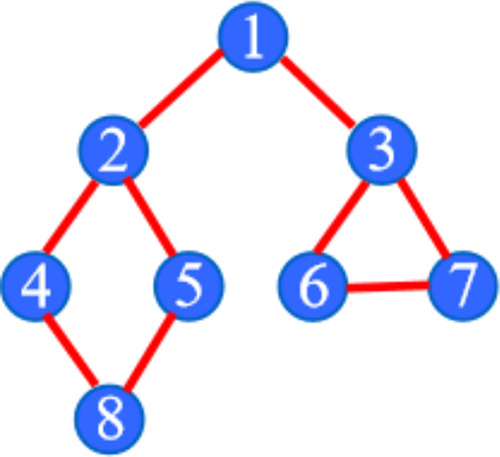
Schematic diagram of the depth-first traversal algorithm traversing the grid.
This access strategy prioritizes vertical mining, rather than horizontal access to all adjacent nodes of a node. The specific algorithm is described as follows:
-
(1)
Access the initial node v and mark it as accessed.
-
(2)
Find the first adjacent node w of node v.
-
(3)
If w exists, continue to execute 4, otherwise the algorithm ends.
-
(4)
If w is not accessed, perform depth-first traversal recursion on w (i.e., treat w as another v and proceed to step 123).
-
(5)
Find the next adjacent node of the w adjacent node of node v and proceed to step 3.
As an example, the depth priority traversal order in the following figure is 1 → 2→4 → 8→5 → 3→6 → 7.
4.2. Extraction Results of Connected Units
It should be pointed out that in the process of extracting connected units from wells, static data alone cannot be relied on. It is necessary to fully consider the dynamic understanding of the target reservoir based on static data. Manually adjust the position relationship of cracks and pores to obtain connected units. This is because the process of extracting fractures and caves is mainly based on seismic data, which contains a large number of artificially determined boundaries and parameters. Due to the relatively low accuracy of seismic data and the uncertainty of various algorithm parameters. Therefore, the static geological model of fissures and caves is only an approximation of the actual geological situation. The dynamic information on production reflects the laws of underground fluid seepage, which more accurately reflects the connectivity relationship. Therefore, adjustments need to be made using dynamic data. Figure 9 shows the extraction process of connected units in the southern zone of T-12518. It can be seen that there is a significant difference between the connected units extracted solely from static data and the connected units reextracted after fine-tuning the crack position considering dynamic data (Figure 10). In fact, based on the results of dynamic understanding, the T-12518 southern zone is divided into three fissure cave units. The area is marked with three colors in Figure 10. From south to north, there are T-12547H and T-12518CH units in sequence; T-12548CH, T-12536X, T-12562H units; T-12553, T-12538H units.
Figure 9.

Extraction process of connected units in the southern zone of T-12518.
Figure 10.

Extraction results of the connected units in the northern zone of T-12518.
Similarly, after fine-tuning the coordination relationship between fractures and caves in the northern zone of T-12518 based on dynamic understanding, the extracted connected units are shown in Figure 10. From the perspective of connectivity, it is divided into 5 units, with T-12546 single well-isolated units from south to north in sequence; T-12560X, T-12532, T-12535, T-12549H, T-12540 units; T-12516X, T-12557X units; T-12541, T-12531X units; T-12553, T-12537X, T-12567X units.
5. Conclusions
In this paper, first, the comprehensive geological research results were fully applied to establish geological models. Then, in response to the geological characteristics of carbonate fractured and vuggy reservoirs, various data are integrated. Third, a refined geological model of the oil reservoir in the study area is established.
-
(a)
From the geological characteristics, the T-12518 fault zone can be divided into two sections. The main contradiction faced by the development of the strip is that the northern part of the fault is mainly affected by water content, while the southern part has significant energy differences.
-
(b)
Complete the construction of a numerical model for the T-12518 fault zone, adjust porosity, change elastic properties, and slow down water breakthrough in oil wells. By adjusting permeability, improving flow capacity, and fitting wellhead pressure. By adjusting the energy of the water body, the water breakthrough speed of the oil well can be changed.
-
(c)
After the above adjustments, the fitting results of oil, water, and pressure are good, meeting the requirements of development strategy analysis. After simulation, the total reserves in the connected units of the six fault solution bodies of the T-12518 belt are 11.67 million tons, with a remaining reserve of 10.47 million tons.
Acknowledgments
The authors acknowledge China Petroleum Major Science and Technology Project: Research on Beneficial Development and Enhanced Oil Recovery of Ultra Deep Fault Controlled Carbonate Reservoir. (No.: 2023ZZ16YJ02).
The authors declare no competing financial interest.
References
- Meng S.; Li D.; Liu X.; et al. Study on dynamic fracture growth mechanism of continental shale under compression failure. Gas Sci. Eng. 2023, 114, 204983 10.1016/j.jgsce.2023.204983. [DOI] [Google Scholar]
- Liu B.; Mohammadi M.; Ma Z.; Bai L.; Wang L.; Xu Y.; Ostadhassan M.; Hemmati-Sarapardeh A. Evolution of porosity in kerogen type I during hydrous and anhydrous pyrolysis: Experimental study, mechanistic understanding, and model development. Fuel 2023, 338, 127149 10.1016/j.fuel.2022.127149. [DOI] [Google Scholar]
- Liu B.; Song Y.; Zhu K.; Su P.; Ye X.; Zhao W. Mineralogy and element geochemistry of salinized lacustrine organic-rich shale in the Middle Permian Santanghu Basin: Implications for paleoenvironment, provenance, tectonic setting and shale oil potential. Mar. Pet. Geol. 2020, 120, 104569 10.1016/j.marpetgeo.2020.104569. [DOI] [Google Scholar]
- Liu X.; Meng S. W.; Liang Z. Z.; et al. Microscale crack propagation in shale samples using focused ion beam scanning electron microscopy and three-dimensional numerical modeling. Pet. Sci. 2023, 20 (3), 1488–1512. 10.1016/j.petsci.2022.10.004. [DOI] [Google Scholar]
- Liu B.; Yang Y.; Li J.; Chi Y.; Li J.; Fu X. Stress sensitivity of tight reservoirs and its effect on oil saturation: A case study of Lower Cretaceous tight clastic reservoirs in the Hailar Basin, Northeast China. J. Pet. Sci. Eng. 2020, 184, 106484 10.1016/j.petrol.2019.106484. [DOI] [Google Scholar]
- Liu H.; Kuang L. C.; Li G. X. Considerations and suggestions on optimizing completion methods of continental shale oil in China. Acta Pet. Sin. 2020, 41 (04), 489–496. 10.7623/syxb202004011. [DOI] [Google Scholar]
- Liu B.; Sun J.; Zhang Y.; He J.; Fu X.; Yang L.; Xing J.; Zhao X. Reservoir space and enrichment model of shale oil in the first member of Cretaceous Qingshankou Formation in the Changling sag, southern Songliao Basin, NE China. Pet. Explor. Dev. 2021, 48 (3), 608–624. 10.1016/S1876-3804(21)60049-6. [DOI] [Google Scholar]
- Liu B.; Wang H.; Fu X.; Bai Y.; Bai L.; Jia M.; He B. Lithofacies and depositional setting of a highly prospective lacustrine shale oil succession from the Upper Cretaceous Qingshankou Formation in the Gulong Sag, northern Songliao Basin, Northeast China. AAPG Bull. 2019, 103, 405–432. 10.1306/08031817416. [DOI] [Google Scholar]
- Tao J. P.; Meng S. W.; Li D. X.; et al. Analysis of CO2 effects on porosity and permeability of shale reservoirs under different water content conditions. Geoenergy Sci. Eng. 2023, 226, 2949–8910. 10.1016/j.geoen.2023.211774. [DOI] [Google Scholar]
- Liu H.; Meng S. W.; Wang S. L. Mechanical characteristics and fracture propagation mechanism of the Gulong shale. Oil Gas Geol. 2023, 44 (04), 820–828. [Google Scholar]
- Yuan B.; Zhao Z. M.; Meng S. W.; et al. Intelligent identification and real-time warning method of diverse complex events in horizontal well fracturing. Pet. Explor. Dev. 2023, 50, 1487–1496. 10.1016/S1876-3804(24)60482-9. [DOI] [Google Scholar]
- Liu H.; Huang Y. Q.; Cai M. Practice and development suggestions for hydraulic fracturing technology in the Gulong shale oil reservoirs in Songliao Basin, NE China. Pet. Explor. Dev. 2023, 50 (03), 603–612. [Google Scholar]
- Meng S. W.; Zhang Z. H.; Tao J. P. A Novel Upscaling Method for Evaluating Mechanical Properties of the Shale Oil Reservoir Based on Cluster Analysis and Nanoindentation. J. Energy Resour. Technol. 2023, 145 (11), 112901 10.1115/1.4062248. [DOI] [Google Scholar]
- Yu H.; Xu W. L.; Li B.; et al. Hydraulic Fracturing and Enhanced Recovery in Shale Reservoirs: Theoretical Analysis to Engineering Applications. Energy Fuels 2023, 37 (14), 9956–9997. 10.1021/acs.energyfuels.3c01029. [DOI] [Google Scholar]
- Yue P.; Xie Z.; Huang S.; Liu H.; Liang S.; Chen X. The application of N2 huff and puff for IOR in fracture-vuggy carbonate reservoir. Fuel 2018, 234, 1507–1517. 10.1016/j.fuel.2018.07.128. [DOI] [Google Scholar]
- Li P.; Zhao Y.; Liu B.; Zeng G.; Zhang T.; Xu D.; Gu H.; Gu T.; Wang F. Experimental testing and numerical simulation to analyze the corrosion failures of single well pipelines in Tahe oilfield. Eng. Failure Anal. 2017, 80, 112–122. 10.1016/j.engfailanal.2017.06.014. [DOI] [Google Scholar]
- Li H.; Wang G.; Li Y.; Bai M.; Pang X.; Zhang W.; Zhang X.; Wang Q.; Ma X.; Lai J. Fault-karst systems in the deep Ordovician carbonate reservoirs in the Yingshan Formation of Tahe Oilfield Tarim Basin, China. Geoenergy Sci. Eng. 2023, 231 (Part A), 212338 10.1016/j.geoen.2023.212338. [DOI] [Google Scholar]
- Tian F.; Zhang J.; Zheng W.; Zhou H.; Ma Q.; Shen C.; Ma Q.; Lan M.; Liu Y. Geology-geophysics-data mining” integration to enhance the identification of deep fault-controlled paleokarst reservoirs in the Tarim Basin. Mar. Pet. Geol. 2023, 158 (Part A), 106498 10.1016/j.marpetgeo.2023.106498. [DOI] [Google Scholar]
- Zhao X.; Wu C.; Ma B.; Li F.; Xue X.; Lv C.; Cai Q. Characteristics and genetic mechanisms of fault-controlled ultra-deep carbonate reservoirs: A case study of Ordovician reservoirs in the Tabei paleo-uplift, Tarim Basin, western China. J. Asian Earth Sci. 2023, 254, 105745 10.1016/j.jseaes.2023.105745. [DOI] [Google Scholar]
- Hui G.; Chen Z.; Schultz R.; Chen S.; Song Z.; Zhang Z.; Song Y.; Wang H.; Wang M.; Gu F. Intricate unconventional fracture networks provide fluid diffusion pathways to reactivate pre-existing faults in unconventional reservoirs. Energy 2023, 282, 128803 10.1016/j.energy.2023.128803. [DOI] [Google Scholar]
- Marinković G.; Papić P.; Spahić D.; Andrijašević J.; Spahić M. P. Case study of mountainous geothermal reservoirs (Kopaonik Mt.; southwestern Serbia): Fault-controlled fluid compartmentalization within a late Paleogene-Neogene core-complex. Geothermics 2023, 114, 102799 10.1016/j.geothermics.2023.102799. [DOI] [Google Scholar]
- Ma X.; Li H.; Luo H.; Nie S.; Gao S.; Zhang Q.; Yuan F.; Ai W. Research on well selection method for high-pressure water injection in fractured-vuggy carbonate reservoirs in Tahe oilfield. J. Pet. Sci. Eng. 2022, 214, 110477 10.1016/j.petrol.2022.110477. [DOI] [Google Scholar]
- Gu H.; Kang Z.; Shang G.; Zheng S.; Zhu G.; Zhang Y.; Zhu X.; Zhu L. Analysis of main controlling factors for elastic flooding productivity of ultra-deep fault-karst reservoirs based on material balance. Pet. Geol. Recovery Effic. 2021, 28 (4), 86–92. 10.13673/j.cnki.cn37-1359/te.2021.04.010. [DOI] [Google Scholar]
- Hu X.; Zheng W.; Zhao X.; Niu B. Quantitative characterization of deep fault-karst carbonate reservoirs: A case study of the Yuejin block in the Tahe oilfield. Energy Geosci. 2023, 4 (3), 100153 10.1016/j.engeos.2022.100153. [DOI] [Google Scholar]
- Zhang H.; Cai Z.; Hao F.; Hu W.; Lu X.; Wang Y. Hypogenic origin of paleocaves in the Ordovician carbonates of the southern Tahe oilfield, Tarim basin, northwest China. Geoenergy Sci. Eng. 2023, 225, 211669 10.1016/j.geoen.2023.211669. [DOI] [Google Scholar]
- Han C.; Lin C.; Lu X.; Tian J.; Ren L.; Ma C. Petrological and geochemical constraints on fluid types and formation mechanisms of the Ordovician carbonate reservoirs in Tahe Oilfield, Tarim Basin, NW China. J. Pet. Sci. Eng. 2019, 178, 106–120. 10.1016/j.petrol.2019.03.010. [DOI] [Google Scholar]
- Xu J.; Ye X.; Liu X.; Li J.; Wang P. Key techniques for quantitative characterization of fractured reservoirs with different lithology. Pet. Geol. Recovery Effic. 2023, 30 (5), 41–48. 10.13673/j.pgre.202210005. [DOI] [Google Scholar]
- Fan H.; Shi J.; Fan T.; Gao Z.; Gu Y.; Gao Z.; Zhang T.; Li Y.; Li B. Sedimentary microfacies analysis of carbonate formation based on FMI and conventional logs: A case study from the ordovician in the Tahe Oilfield, Tarim Basin, China. J. Pet. Sci. Eng. 2021, 203, 108603 10.1016/j.petrol.2021.108603. [DOI] [Google Scholar]
- Li Y.; Sun J.; Wei H.; Song S. Architectural features of fault-controlled karst reservoirs in the Tahe oilfield. J. Pet. Sci. Eng. 2019, 181, 106208 10.1016/j.petrol.2019.106208. [DOI] [Google Scholar]
- Tian F.; Jin Q.; Lu X.; Lei Y.; Zhang L.; Zheng S.; Zhang H.; Rong Y.; Liu N. Multi-layered ordovician paleokarst reservoir detection and spatial delineation: A case study in the Tahe Oilfield, Tarim Basin, Western China. Mar. Pet. Geol. 2016, 69, 53–73. 10.1016/j.marpetgeo.2015.10.015. [DOI] [Google Scholar]
- Qiao J.; Tang X.; Hu M.; Rutqvist J.; Liu Z. The hydraulic fracturing with multiple influencing factors in carbonate fracture-cavity reservoirs. Comput. Geotech. 2022, 147, 104773 10.1016/j.compgeo.2022.104773. [DOI] [Google Scholar]
- Li Y.-B.; Pu W.; Wei B.; Chen Y.; Bai B. The feasibility of CO2 and N2 injection for the Tahe fracture-cavity carbonate extra-heavy oil reservoir: An experimental study. Fuel 2018, 226, 598–606. 10.1016/j.fuel.2018.04.056. [DOI] [Google Scholar]
- Shi L. Experimental study on calculating method of water flooding radius in ultra-low permeability. Unconv. Oil Gas 2024, 11 (02), 66–73. 10.19901/j.fcgyq.2024.02.08. [DOI] [Google Scholar]
- Sun F.; Yao Y.; Chen M.; Li X.; Zhao L.; Meng Y.; Sun Z.; Zhang T.; Feng D. Performance analysis of superheated steam injection for heavy oil recovery and modeling of wellbore heat efficiency. Energy 2017, 125, 795–804. 10.1016/j.energy.2017.02.114. [DOI] [Google Scholar]
- Lyu X.; Ju B.; Li H.; Wu X.; Bu C.; Xia D. Classification, modeling and characterization of marine carbonate paleokarst reservoirs in Tahe Oilfield, Tarim Basin, China. Carbonates Evaporites 2023, 38, 42 10.1007/s13146-023-00867-9. [DOI] [Google Scholar]
- Yuan C.-D.; Pu W.; Jin F.; Zhang Y.; Jia H.; Zhao T. Performance of Oil-Based Cement Slurry as a Selective Water-Plugging Agent in High-Temperature and High-Salinity Cave-Fractured Carbonate Reservoirs. Ind. Eng. Chem. Res. 2014, 53 (14), 6137–6149. 10.1021/ie4000129. [DOI] [Google Scholar]
- Dong S.; He L.; Li L.; Wu Y.; Wang X. Investigation of Polyvinyl Alcohol–Phenolic Aldehyde–Polyacrylamide Gel for the Application in Saline Oil Reservoirs for Profile Modification. Energy Fuels 2023, 37 (18), 13710–13720. 10.1021/acs.energyfuels.3c02178. [DOI] [Google Scholar]
- Tang K.; Su Z.; Zhao Y.; Xie H.; Zhang H.; Xu Z.; Shi C.; Wang G.; Zhu D. Water Management and Oil Recovery Improvement Performance of High-Strength Preformed Particle Gels in Fractured Conglomerate Reservoirs. Energy Fuels 2023, 37 (14), 10287–10295. 10.1021/acs.energyfuels.3c01739. [DOI] [Google Scholar]
- Zhu S. Characteristics of hydrothermal fluid activity and its petroleum geological significance in Jiyang Depression. Unconv. Oil Gas 2024, 11 (02), 21–28. 10.19901/j.fcgyq.2024.02.03. [DOI] [Google Scholar]
- Sun F.; Yao Y.; Li X. The Heat and Mass Transfer Characteristics of Superheated Steam Coupled with Non-condensing Gases in Horizontal Wells with Multi-point Injection Technique. Energy 2018, 143, 995–1005. 10.1016/j.energy.2017.11.028. [DOI] [Google Scholar]
- Shen W.; Pang X.; Chen J.; Zhang K.; Chen Z.; Gao Z.; Luo G.; He L. Ordovician Hydrocarbon Migration along the Tazhong No. 10 Fault Belt in the Tazhong Uplift, Tarim Basin, Northwest China. Energy Fuels 2018, 32 (2), 1474–1490. 10.1021/acs.energyfuels.7b03542. [DOI] [Google Scholar]
- Guo A.; Tang X.; Qiao J.; Zhou L.; Luo P. Three-dimensional simulation of the acidizing process under different influencing factors in fractured carbonate reservoirs. Energy Sci. Eng. 2023, 11 (9), 3102–3118. 10.1002/ese3.1507. [DOI] [Google Scholar]
- Sun F.; Yao Y.; Li G.; Li X. Numerical Simulation of Supercritical-Water Flow in Concentric-Dual-Tubing Wells. SPE J. 2018, 23 (6), 2188–2201. 10.2118/191363-PA. [DOI] [Google Scholar]
- Sun F.; Yao Y.; Li G.; Li X. Geothermal energy extraction in CO2 rich basin using abandoned horizontal wells. Energy 2018, 158, 760–773. 10.1016/j.energy.2018.06.084. [DOI] [Google Scholar]
- Jing W.; Zhang L.; Li A.; Yang Y.; Zhong J.; Sun H.; Yao J. Investigation of Pore-Scale Remaining Oil Dynamic Evolution in Heterogeneous Marine Carbonate Using Real-Time Computed Tomography Scanning. Energy Fuels 2022, 36 (15), 8180–8188. 10.1021/acs.energyfuels.2c01497. [DOI] [Google Scholar]
- Sun F.; Yao Y.; Li G.; Li X. Performance of geothermal energy extraction in a horizontal well by using CO2 as the working fluid. Energy Convers. Manage. 2018, 171, 1529–1539. 10.1016/j.enconman.2018.06.092. [DOI] [Google Scholar]
- Li H.; Wang Q.; Qin Q.; Ge X. Characteristics of Natural Fractures in an Ultradeep Marine Carbonate Gas Reservoir and Their Impact on the Reservoir: A Case Study of the Maokou Formation of the JLS Structure in the Sichuan Basin, China. Energy Fuels 2021, 35 (16), 13098–13108. 10.1021/acs.energyfuels.1c01581. [DOI] [Google Scholar]
- Sun F.; Yao Y.; Li G.; Li X. Geothermal energy development by circulating CO2 in a U-shaped closed loop geothermal system. Energy Convers. Manage. 2018, 174, 971–982. 10.1016/j.enconman.2018.08.094. [DOI] [Google Scholar]
- Liu X.; Wang X.; Wang J.; Liu X.; Chen L.; Xin A.; Tian S.. Investigation of the film-forming flooding mechanism of molecular deposition in tight oil reservoirs Pet. Sci. Technol. 2023 10.1080/10916466.2023.2234948. [DOI]
- Esfe M. E. Using a two-phase method for numerical natural convection simulation in a cavity containing multiwalled carbon nanotube/water. J. Therm. Anal. Calorim. 2021, 146, 757–773. 10.1007/s10973-020-09950-y. [DOI] [Google Scholar]
- Guowei Q.; Liu Q.; Zhang B.; Sun S.; Zheng Y.; Qin W.; Wu M. Investigate on mechanism of nanofluid drainage gas recovery in tight gas reservoir. Pet. Sci. Technol. 2022, 40 (3), 351–361. 10.1080/10916466.2021.1998117. [DOI] [Google Scholar]
- Labus K.; Labus M. Thermogravimetry as a tool for measuring of fracturing fluid absorption in shales. J. Therm. Anal. Calorim. 2018, 133, 919–927. 10.1007/s10973-018-7172-4. [DOI] [Google Scholar]
- Wang J.; Zhou F.; Xue Y.; Yao E.; Zhang L.; Fan F.; Wang R. The adsorption properties of a novel ether nanofluid for gas wetting of tight sandstone reservoir. Pet. Sci. Technol. 2019, 37 (12), 1436–1454. 10.1080/10916466.2019.1590402. [DOI] [Google Scholar]
- Polikhronidi N. G.; Batyrova R. G.; Abdulagatov I. M. Heat capacity of (ethanol + diamond) nanofluid near the critical point of base fluid (ethanol). J. Therm. Anal. Calorim. 2019, 135, 1335–1349. 10.1007/s10973-018-7475-5. [DOI] [Google Scholar]
- Zhong C.; Qin Q.; Fan C.; Hu D. Effect of nanometer pore structure on methane adsorption capacity in organic-rich shale. Pet. Sci. Technol. 2019, 37 (11), 1243–1250. 10.1080/10916466.2018.1542443. [DOI] [Google Scholar]
- Ramezanpour M.; Siavashi M. Application of SiO2–water nanofluid to enhance oil recovery. J. Therm. Anal. Calorim. 2019, 135, 565–580. 10.1007/s10973-018-7156-4. [DOI] [Google Scholar]
- Karimi-Fard M.; Durlofsky L. J.; Aziz K. An Efficient Discrete-Fracture Model Applicable for General-Purpose Reservoir Simulators. SPE J. 2004, 9 (2), 227–236. 10.2118/88812-PA. [DOI] [Google Scholar]