

Abstract
Head movement must be stabilized to enable high-quality data collection from optical instrumentation such as eye trackers, and ophthalmic imaging devices. Though critically important for imaging, head stabilization is often an afterthought in the design of advanced ophthalmic imaging systems and experimental devices often adapt used and/or discarded equipment from clinical devices for this purpose. Alternatively, those seeking the most stable solution possible, including many users of adaptive optics ophthalmoscopy systems, utilize bite bars. Bite bars can provide excellent stability but are time consuming to fabricate, decreasing imaging efficiency, and uncomfortable for many patients, especially the elderly and/or those with prosthodontics such as dentures who may refuse participation in a study that requires one. No commercial vendors specifically offer head mount solutions for experimental ophthalmic imaging devices, resulting in nearly every custom device having a different solution for this commonly encountered problem. Parallelizing the head stabilization apparatus across different custom devices may improve standardization of experimental imaging systems for clinical trials and other multi-center investigations. Here we introduce a head mount design for ophthalmic imaging that is modular, adjustable, and customizable to the constraints of different experimental imaging configurations. The 3-points of head contact in our solution provides excellent stabilization across a range of head sizes and shapes from small children to adults, and the ease of adjustment afforded by our design minimizes the time to get participants stabilized and comfortable.
1. Introduction
Over the past few decades, retinal imaging technology has been rapidly advancing as traditional flood-illumination fundus cameras have been supplanted in many use cases by scanning-based imaging systems, such as optical coherence tomography (OCT), as they provide valuable information that cannot be obtained using fundus photography [1]. However, with point-scanning, the exposure times have also increased to allow for image averaging to increase signal-to-noise ratio (SNR), rendering the images vulnerable to artifacts caused by eye motion [2]. This is especially the case with adaptive optics scanning laser ophthalmoscopes (AOSLO) where eye movements are magnified by the small field of view (FOV) of these devices that is typically on the order of 1–2 degrees (~300 to 600 μm) [3]. In optical coherence tomography (OCT), the axial movement of the eye causes uncertainty in the measurements, which can be mitigated with image processing [4] and by tracking the axial motion [5]. Other experimental devices and custom imaging systems, such as eye trackers [6,7] and laser doppler holography systems [8], also benefit from having the head stabilized during the measurement.
In research-grade systems, there are no commercial options available for head mounts and often these are recycled from old slit-lamps or in some cases the imaging system is built on the old commercial platform itself taking advantage of the frame and previous design. For high-resolution systems using adaptive optics (AO) that often have a larger footprint, the more common alternative has been to use a bite bar, which requires making a dental impression mold of the teeth using dental impression compound over a metal frame. A bite bar can provide excellent stabilization; however, they have several drawbacks. First, they take some time to fabricate, even when using fast setting dental impression compounds that do not require the use of hot water for fabrication. Minimizing the time from patient arrival to actual imaging reduces any fatigue-related issues from arising during imaging, especially for those patients that come to the lab from a busy day of testing in the clinic and may already be tired, further optimizing the potential for best image quality. Second, fabrication can be challenging depending on the patient, as elderly patients, and children can have difficulty making the dental impression level and not either too deep, which can cause them to bite down on the metal substrate, or too shallow, which can impact alignment and stability. Fabrication can also introduce some tip or tilt between the axis of the bite bar and the optical axis of the eye, and this can also be variable depending on how the bite bar is mounted. Patient comfort is also a major concern because even well fabricated bite-bars can be uncomfortable to use, especially for periods longer than a few minutes. Further, some elderly participants or others with jaw conditions such as temporomandibular joint, including those with prosthodontics such as dentures will refuse to participate in studies that require a bite bar. This presents a challenge for clinical/translational use of experimental ophthalmic imaging and testing devices as many diseases of interest for imaging, such as glaucoma and age-related macular degeneration (AMD), are seen mostly or only in older eyes. Finally, since they must go inside the mouth, bite bars present a greater infection risk than non-invasive approaches; this is something that is a concern for the storage and handling of bite bars for longitudinal studies and that became particularly relevant over the past few years as coronavirus disease 2019 (COVID-19) precautions had mandated the wearing of masks in clinical environments.
To streamline imaging in experimental systems we designed a modular head mount for ophthalmic imaging that is specifically designed for experimental research systems. All features of the head mount are adjustable and can be easily redesigned according to e.g., space restrictions. The modularity of the design allows individual components to be redesigned for other purposes without having to redesign the whole apparatus. The head mount was originally designed for retinal imaging in AOSLO system but has since been adapted for use in several other retinal imaging systems including a custom flood-illumination adaptive optics imaging system, a laser doppler holography system, a binocular eye tracking setup used for psychophysics applications, and a full field optical coherence tomography system. Though the most stringent experimental conditions, such as individual photoreceptor stimulation [9], may still require the use of a bite bar, our head stabilization apparatus appears suitable for most experimental ophthalmic imaging system applications.
2. The design
When designing the mount, we identified several design criteria that were mandatory based on our experience. These features were:
Ease of use for the operator to minimize patient’s time in the system that is not active imaging (downtime).
Modularity: each part can be redesigned individually, if necessary, without redesigning the whole head mount from scratch. This allows different mounting scenarios for different systems.
Open access: Design files are in standard format (.stp, .stl and .f3z) so others can easily utilize them and make their own modifications/improvements, as needed.
Low cost: 3D printing was utilized, when possible, to minimize costs and simplify fabrication.
Firstly, the mount had to accommodate different head sizes [10,11]. The flexible headband approach that most commercial systems use is not satisfactory for high-resolution imaging as they allow too much movement due to a single contact used across the forehead that minimizes forward/backward movement if the head is kept resting on the strap but does nothing to minimize side-to-side motion. We decided to adapt a 3-point contact approach that has been used successfully in adaptive optics ophthalmoscopy (AAO) [12–14]. These systems utilize bite bars and have two temple pads to provide the three points in space. But instead of the bite bar for the third contact point we opted for a deep chinrest cup where the patient could push/press against it allowing them to remain stable without slipping.
The head mount components were designed using Fusion 360 (Autodesk, San Francisco, CA, United States). Additive manufacturing was used for every part that was not load bearing. The head mount consists of a base plate, vertical support columns, the chinrest slider, head band and forehead slider modules. Figure 1(a) shows the first modeled head mount and Fig. 1(b) is the photo of the assembled head mount installed in the AOSLO system [15]. The base plate seen in Fig. 1(a) can be customized to the specific imaging system if the chinrest cup elements and vertical support column mounting holes are kept the same in the new baseplate design. For the first design, the baseplate was adapted to connect to a motorized 3-axis translation stage (BiSlide motor driven assembly, Velmex, Inc., Bloomfield, NY). To keep the vertical adjustment range equal for up and down movement and considered the fixed height of the optical axis of the imaging system, we designed the baseplate with a specific shape (seen in Fig. 1).
Figure 1.
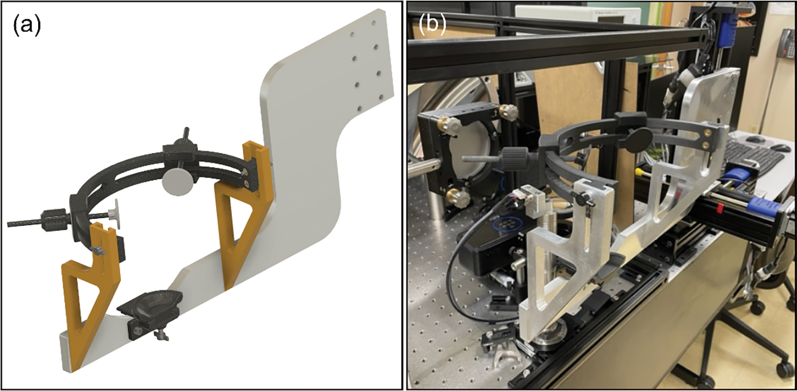
The assembled head mount for high-resolution imaging. (a) The CAD drawing was done in Fusion 360 which allowed us to easily visualize the final product and verify that biometric values for head dimensions would work. (b) A photograph of the manufactured and installed head mount in the lab of Dr. Rossi (University of Pittsburgh). The reason why the base plate extends all the way to the right is due to the large 3-axis motorized stages that allowed the head positioning remotely.
For initial modeling, standard biometrics were used from the literature [10,16,17]. The diameter of the headband was chosen to fit an averaged size head (18 cm in diameter) with room to adjust for both directions, larger and smaller (Fig. 2(a)). Also, the height of the head band could be altered, ranging from 14 to 19 cm as can be seen from Fig. 2(b). Besides these two parameters, the chin cup was movable to provide more comfort to the patient if needed, depending on the shape of their face and relative position of chin and forehead (Fig. 2(c)). Finally, the forehead sliders seen in Fig. 2(a) can be moved radially in the headband and the temple pads can be adjusted with the rod to accommodate different sized heads. To lock the pads in place, the tapered nut design clamps the rod in place when it is tightened. This provides a fast method for the operator to quickly adjust the pads for each individual patient. In terms of getting patient ready for imaging, it takes around one minute to get them from just sitting into the chinrest to getting them aligned with the system.
Figure 2.
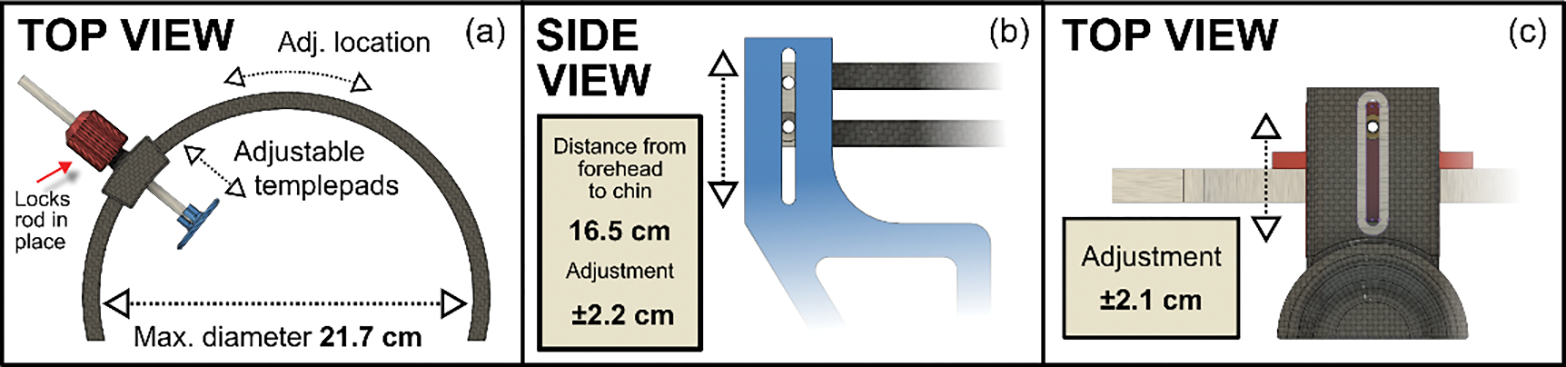
The adjustment range of the different parameters. (a) The maximum diameter of the headband was 21.7 cm which is approximately 4 cm larger than the averaged head, allowing room for larger heads. The temple pads could be slid anywhere in the headband itself and adjusted with the rod to provide a sturdy head mounting. (b) Although the pads are placed roughly on the forehead 99% of the cases, the headband height can be adjusted for people with longer heads or in case the contact points are wanted higher/lower on the patient for some reason (e.g., spectacles). (c) Due to variation of the relative depth of individuals’ chins, it was also important to allow the chinrest to move back and forth for comfort.
The T-slot design for the headband height adjustment allows future extension of the available range if required. The same goes for the length of the chinrest sliding module as it can be lengthened or shortened in the model by just extruding the component in one dimension. Not including several off-the-shelf components such as nuts, bolts and thread inserts, the exploded view in Fig. 3 shows all 17 components for the head mount apparatus.
Figure 3.
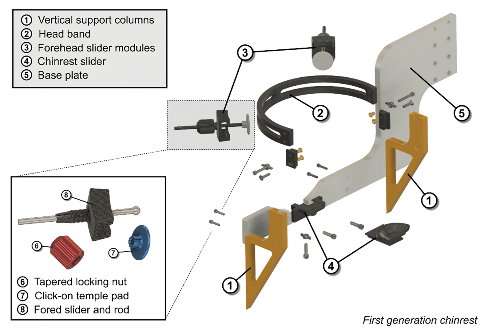
An exploded view of the first-generation head mount to show all the fabricated components. A total of 13 different parts were designed out of which 3 were CNC machined (the base plate and the vertical support columns). To interface the plastic parts with screws, off-the-shelf thread inserts were used and melted into the 3D-printed parts. Besides these inserts, only standards screws were used.
Fully detailed manufacturing descriptions are provided in the manual in the GitHub repository page [18]. The GitHub repository also contains cad files for each component as well as 3D-printing files for all the parts that are not made with aluminum. In the manual the individual off-the-shelf components are also listed along with the instructions for assembling the head mount.
3. The deployment of the head mounts
The first version of the head mount was installed on the Pittsburgh AOSLO system at the University of Pittsburgh in March 2018 and as of Fall 2023, 258 patients has been successfully imaged ranging from normal healthy aging to age-related macular degeneration patients [15,19] and also rare ocular conditions such as torpedo maculopathy [20].
In the lab at Pittsburgh, complaints regarding discomfort have been minimal. A few patients have mentioned that the cup where the chin is placed is too short/small, but this is something that can be easily redesigned and manufactured using 3D-printing without having to adjust the other parts of the head mount.
We have also produced three additional units, each varying slightly from our original design, for deployment in other experimental ophthalmic devices. The second unit was fabricated in 2021 for use in a binocular eye tracking system in Dr. Patrick Mayo’s lab at the University of Pittsburgh [21] with modifications to the mounting baseplate and chinrest slider (see Fig. 4(a)) to accommodate the constraints of their system. Here the long arm of the original baseplate was modified for direct table-top mounting of the unit. This mounting configuration did not allow for the hand screw that holds the chin cup in place to be accessed from beneath, so the chinrest slider was modified so that it could be adjusted from above. A third unit was fabricated in the spring of 2023 for use in a laser doppler holography system [8] at the University of Pittsburgh (Fig. 4(b)), this version also modified the mounting baseplate, here reverting back to a mounting arm similar to version one but adapted here for use with a manual 3-axis translation stage (UniSlide XYZ System, Velmex, Inc., Bloomfield, NY). Additionally, again due to constraints imposed by the optical system, the chin cup was modified to remove the longer extruded portion of the dove tail base to prevent it from hitting the optical system when in its forward position. One potential future modification for this unit that we are considering is to extend the vertical support columns upwards slightly as main objective lens of the instrument has a large diameter that can become very close to bumping the headband even when it is at its highest point. A fourth device (Fig. 4(c)) was fabricated in the summer of 2023 for use in a full-field optical coherence tomography (FF-OCT) system [22]. Since this device allows for axial and lateral positioning of the optical system, the only axis the head was required to move in was the vertical axis. This adjustment capability was provided by mounting the base plate of the device onto a lab jack (L490, Thorlabs; Newton, NJ, USA). For this unit, we modified the table-mounted version of the base plate used in the eye tracking system to be slightly taller and adapted the mounting holes to the lab jack. Finally, aside from these four mounts, additional two units are being planned to be used in UC Davis and University of Turku on an OCT system for optoretinography (ORG) [23].
Figure 4.

Three additional variations of the baseplate and the chinrest mounting to accommodate unique space requirements for different retinal imaging setups. (a) Chinrest where the baseplate was adapted for eye tracking system used in primates (b) LDH system which had manual 3-axis translation stage to control the head (c) Full-field OCT (FF-OCT) imaging system where only vertical motion was required as the system itself could adjust horizontal and axial motion. Below the 3D renderings, photos from the installed head mounts are shown.
4. Discussion and Conclusion
This novel, modular, chin and forehead rest system can reliably stabilize the head/eye for a range of ophthalmic testing and imaging devices. The first generation of this device allowed for high-resolution imaging in patients using an AOSLO without the need for a bite bar. The functionality of the head mount was proven invaluable from the operator’s perspective as the alignment of new patients was effortless once they became familiar with the adjustments and was typically done within a minute. The 3-point contact without bite bar allowed for prolonged testing/imaging without any discomfort as the patient did not have to keep biting down on a dental impression mold to maintain the 3-points of contact needed for robust stabilization. Out of the current 258 patients, none has been dropped out from the imaging due to us not being able to mount the head comfortable and stable into the mount.
The radial force that keeps the forehead mount pads in place is sufficient to keep the sliders in place. However, for future improvement some sort of step size control, such as sawtooth shape in the forehead band or pin locking mechanism would be ideal as that would then allow a wider range of pad distances. Another possible modification would be to make the posts holding the forehead pads shorter or more compact, as this would aid in implementation in devices that have space constraints close to the forehead, such as the LDH system mentioned. Another added feature could be a rubberized or silicone surface to the chin cup as that would provide even more friction, though it would be important to choose a material that can be sanitized using alcohol swabs as we use these to clean the device before each imaging session.
As Fig. 4 demonstrates, the modularity requirement we imposed in the beginning of the design process makes it very easy to adapt to various mounting scenarios as every retinal imaging system is different. So far, we have only made changes mostly to the base plate, but the design allows also other parts to be easily redesigned and fitted to the head rest.
Finally, the fourth and last design criteria was low-cost manufacturing. The first version of the headrest costed $2,650 as it also included the cost of the labor and help with the design. The subsequent iterations of different mounts were all roughly $1,500 each, when produced in the university’s own mechanical workshop.
7. Funding sources
This research was supported by NIH grant EY030517 and departmental startup funds from the University of Pittsburgh to EAR. This work was also supported by the NIH CORE Grant P30 EY08098 to the University of Pittsburgh, Department of Ophthalmology, the Eye and Ear Foundation of Pittsburgh, and from an unrestricted grant from Research to Prevent Blindness, New York, NY, USA.
Footnotes
Disclosures
The authors declare no conflicts of interest.
6. Data availability statement
All the design files can be uploaded from the project’s GitHub repository (Ref. [18]).
References
- 1.Abràmoff MD, Garvin MK, and Sonka M, “Retinal Imaging and Image Analysis,” IEEE Rev. Biomed. Eng. 3, 169–208 (2010). [DOI] [PMC free article] [PubMed] [Google Scholar]
- 2.Martinez-Conde S, Macknik SL, and Hubel DH, “The role of fixational eye movements in visual perception,” Nat. Rev. Neurosci. 5, 229–240 (2004). [DOI] [PubMed] [Google Scholar]
- 3.Morgan JIW, Chui TYP, and Grieve K, “Twenty-five years of clinical applications using adaptive optics ophthalmoscopy [Invited],” Biomed. Opt. Express 14, 387–428 (2023). [DOI] [PMC free article] [PubMed] [Google Scholar]
- 4.Makita S, Hong Y, Yamanari M, Yatagai T, and Yasuno Y, “Optical coherence angiography,” Opt. Express 14, 7821–7840 (2006). [DOI] [PubMed] [Google Scholar]
- 5.Cai Y, Grieve K, and Mecê P, “Characterization and Analysis of Retinal Axial Motion at High Spatiotemporal Resolution and Its Implication for Real-Time Correction in Human Retinal Imaging,” Front. Med. (Lausanne) 9, (2022). [DOI] [PMC free article] [PubMed] [Google Scholar]
- 6.Sheehy CK, Yang Q, Arathorn DW, Tiruveedhula P, de Boer JF, and Roorda A, “High-Speed, Image-Based Eye Tracking with a Scanning Laser Ophthalmoscope,” Biomed Opt Express 3, 2611–2622 (2012). [DOI] [PMC free article] [PubMed] [Google Scholar]
- 7.Bartuzel MM, Wróbel K, Tamborski S, Meina M, Nowakowski M, Dalasiński K, Szkulmowska A, and Szkulmowski M, “High-resolution, ultrafast, wide-field retinal eye-tracking for enhanced quantification of fixational and saccadic motion,” Biomed Opt Express 11, 3164–3180 (2020). [DOI] [PMC free article] [PubMed] [Google Scholar]
- 8.Puyo L, Paques M, Fink M, Sahel J-A, and Atlan M, “In vivo laser Doppler holography of the human retina,” Biomed. Opt. Express 9, 4113–4129 (2018). [DOI] [PMC free article] [PubMed] [Google Scholar]
- 9.Arathorn DW, Yang Q, Vogel CR, Zhang Y, Tiruveedhula P, and Roorda A, “Retinally stabilized cone-targeted stimulus delivery,” Opt. Express 15, 13731 (2007). [DOI] [PubMed] [Google Scholar]
- 10.Lee J-H, Hwang Shin S-J, and Istook CL, “Analysis of Human Head Shapes in the United States,” Int. J. Hum. Ecol. 7, 77–83 (2006). [Google Scholar]
- 11.Lin Y-C and Chen C-P, “Characterization of small-to-medium head-and-face dimensions for developing respirator fit test panels and evaluating fit of filtering facepiece respirators with different faceseal design,” PLOS ONE 12, e0188638 (2017). [DOI] [PMC free article] [PubMed] [Google Scholar]
- 12.Dubra A and Sulai Y, “Reflective afocal broadband adaptive optics scanning ophthalmoscope,” Biomed. Opt. Express 2, 1757–1768 (2011). [DOI] [PMC free article] [PubMed] [Google Scholar]
- 13.Azimipour M, Jonnal RS, Werner JS, Zawadzki RJ, and Zawadzki RJ, “Coextensive synchronized SLO-OCT with adaptive optics for human retinal imaging,” Opt. Lett. 44, 4219–4222 (2019). [DOI] [PMC free article] [PubMed] [Google Scholar]
- 14.Zhang J, Yang Q, Saito K, Nozato K, Williams DR, and Rossi EA, “An adaptive optics imaging system designed for clinical use,” Biomed. Opt. Express 6, 2120–2137 (2015). [DOI] [PMC free article] [PubMed] [Google Scholar]
- 15.Vienola KV, Zhang M, Snyder VC, Sahel J-A, Dansingani KK, and Rossi EA, “Microstructure of the retinal pigment epithelium near-infrared autofluorescence in healthy young eyes and in patients with AMD,” Sci. Rep. 10, 9561 (2020). [DOI] [PMC free article] [PubMed] [Google Scholar]
- 16.Ball R, Shu C, Xi P, Rioux M, Luximon Y, and Molenbroek J, “A comparison between Chinese and Caucasian head shapes,” Appl. Ergon. 41, 832–839 (2010). [DOI] [PubMed] [Google Scholar]
- 17.Zhuang Z, Shu C, Xi P, Bergman M, and Joseph M, “Head-and-face shape variations of U.S. civilian workers,” Applied Ergonomics 44, 775–784 (2013). [DOI] [PMC free article] [PubMed] [Google Scholar]
- 18.Vienola KV and Rossi EA, “Ophthalmic Imaging Chinrest,” GitHub repository, https://github.com/kvienola/Pitt_chinrest (2023). [Google Scholar]
- 19.Vienola KV, Zhang M, Snyder VC, Dansingani KK, Sahel J-A, and Rossi EA, “Near infrared autofluorescence imaging of retinal pigmented epithelial cells using 663 nm excitation,” Eye (Lond) 36, 1878–1883 (2022). [DOI] [PMC free article] [PubMed] [Google Scholar]
- 20.Vienola KV, Dansingani KK, Eller AW, Martel JN, Snyder VC, and Rossi EA, “Multimodal Imaging of Torpedo Maculopathy With Fluorescence Adaptive Optics Imaging of Individual Retinal Pigmented Epithelial Cells,” Front. Med. (Lausanne) 8, 769308 (2021). [DOI] [PMC free article] [PubMed] [Google Scholar]
- 21.Chroneos MZ, Willet SM, Robert S, Mayo JP, and Behrmann M, “Sinusoidal Smooth Pursuit After Childhood Hemispherectomy,” Journal of Vision 23, 5128 (2023). [Google Scholar]
- 22.Mecê P, Scholler J, Groux K, and Boccara C, “High-resolution in-vivo human retinal imaging using full-field OCT with optical stabilization of axial motion,” Biomed. Opt. Express 11, 492–504 (2020). [DOI] [PMC free article] [PubMed] [Google Scholar]
- 23.Vienola KV, Valente D, Zawadzki RJ, and Jonnal RS, “Velocity-based optoretinography for clinical applications,” Optica 9, 1100–1108 (2022). [Google Scholar]
Associated Data
This section collects any data citations, data availability statements, or supplementary materials included in this article.
Data Availability Statement
All the design files can be uploaded from the project’s GitHub repository (Ref. [18]).