Abstract
Microrobots, untethered miniature devices capable of performing tasks at the microscale, have gained significant attention in the fields of robotics and biomedicine. These devices hold immense potential for various industrial and scientific applications, including targeted drug delivery and cell manipulation. In this study, we present a novel magnetic rolling helical microrobot specifically designed for bio-compatible cell patterning. Our microrobot incorporates both open-loop and closed-loop control mechanisms, providing flexible, precise, and rapid control for various applications. Through experiments, we demonstrate the microrobot’s ability to manipulate cells by pushing them while rolling and arranging cells into desired patterns. This result is particularly significant as it has implications for diverse biological applications such as tissue engineering and organoid development. Moreover, we showcase the effectiveness of our microrobot in a closed-loop control system, where it successfully follows a predetermined path from an origin to a destination. The combination of cellular manipulation capabilities and trajectory-tracking performance underlines the versatility and potential of our magnetic rolling helical microrobot. The ability to control and navigate the microrobot with high precision opens up new possibilities for advanced biomedical applications. These findings contribute to the growing body of knowledge in microbotics and pave the way for further research and development in the field.
Index Terms —: Microrobots, Magnetic actuation, Cell Patterning, Closed-loop control
I. Introduction
The ability to create programmable, controllable machines like microrobots that manage information and execute complex tasks has profoundly impacted various research fields and society as a whole. Industries such as manufacturing, logistics, environmental monitoring, education, and medicine have benefited from the implementations and support of miniature robots [1], [2]. The miniaturization of robotics has emerged as a natural area of research, bringing with it a unique set of challenges regarding autonomy, mobility, and actuation [3], [4]. Consequently, there has been a surge of interest in small-scale robotics, particularly in the development of artificial micro and nanoscale robots [5]–[7], with promising applications in targeted drug delivery [8], [9], regenerative medicine [10], and cellular manipulation [11], [12]. These micro and nanoscale motors exhibit significant diversity in terms of shape, actuation mechanism, and material composition. Researchers have explored various structures to function as microrobots, including Janus-particle-based systems [13]–[15], bacteria-driven robots [16], acoustic microcapsules [17], and magnetic helical structures [18] for in vivo or biomedical application [19]. For bio-compatibility and remote operation, using external energy sources that can penetrate complex structures, such as the human body, is crucial. Therefore, magnetic microrobots have been widely studied in the last few years [20]–[22] as they possess both these attributes and can be designed in various forms [23]. They can also be combined with other actuation modes [17], [24]–[26]. Magnetic microrobots can be used for cell patterning. Current methodologies for cell patterning, such as bioprinting, microfabrication, and microfluidics, are critical in creating a variety of artificial organs outside of the body [27]. However, several limitations prevent the full potential of microrobots in cell patterning.
One issue is the shape of most rolling microrobots. Rotating magnetic fields are often used to actuate these microrobots, offering a more efficient approach than magnetic gradients for small-scale robots. Rolling microrobots can roll on solid surfaces and are typically spherical in shape [11], [28], [29]. While some of these microrobots have demonstrated potential in cell manipulation by pushing or adhering to cells, their working efficiency is limited, and the contact surface with the cells is often minimal [30]–[32]. Another challenge is the complexities associated with size and control. Some studies have explored the closed-loop control of rolling motion [33]–[35], but these focus mainly on microrobots several hundred microns or larger. The small size of a microrobot increases the complexity of its control. Thus, limited research has focused on the automated control of microrobots measuring 10 microns and below.
To address these constraints, we proposed a bio-compatible helical microrobot, actuated by a rolling magnetic field, as illustrated in Fig. 1. Unlike the spherical one, these are specifically designed for enhanced cell manipulation applications. Despite its small size, this unique design ensures high efficiency and precision control. Depending on the application, these rolling microrobots can be controlled using either an open or closed-loop approach. Our study demonstrated that satisfactory tracking performance of the microrobot was achieved, with a peak error of 2.5 μm for a 10 μm long microrobot. This work signifies a step forward in developing low-cost, biocompatible microrobots with a high degree of control. Our proposed approach of cell patterning using microrobots promises enhanced efficiency and safeguards the cells from harm.
Fig. 1:
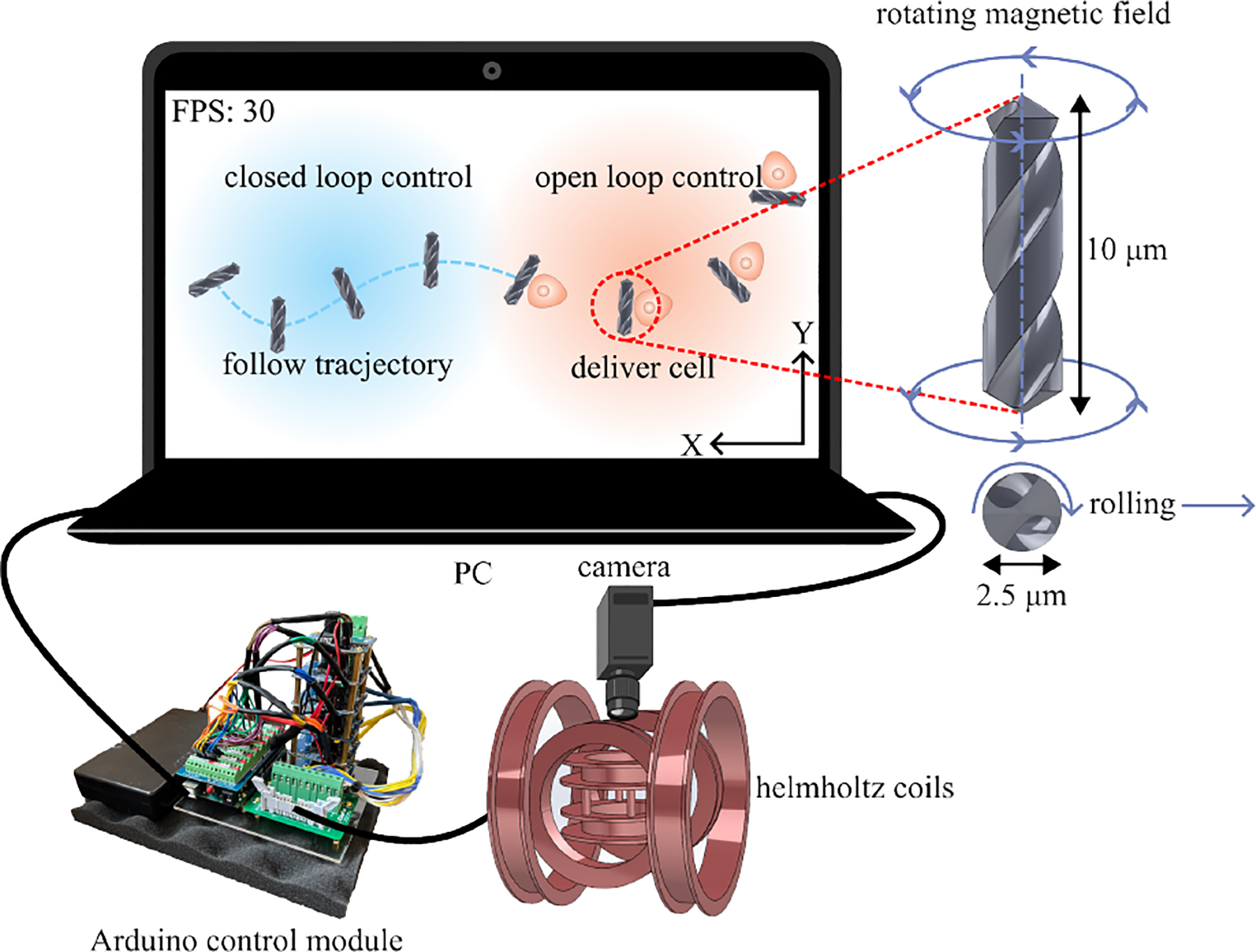
General overview of the proposed system for cell patterning
II. Materials and Methods
A. Microrobot Design and Fabrication
When designing microrobots, certain features need to be considered carefully. The key factor in deciding on the shape is to achieve precise, forward, and controllable motion [36], [37]. Fig. 1 shows the helical microrobots design and the control hardware. The microrobot is a helical construct, approximately 10 μm long and 2.5 μm in diameter. These dimensions were chosen to ensure that the microrobots can roll perpendicular to their rotation axis, as shown in Fig, 3. Our design exhibits two distinct features: Firstly, its dimensions closely match the diameter of a single CHO cell, thereby facilitating single-cell manipulation. Secondly, thread grooves on its surface enable the microrobot to move in a dense cell environment while rolling. Moreover, the rod-like shape is more conducive to manipulating objects than the typical spherical shape. The microrobots were initially designed in SolidWorks before being printed via the two-photon direct laser lithography using a commercially available system (Nanoscribe; Photonic Professional GT) equipped with a 63× objective, and IP-Dip was used as the photoresin. By controlling the laser with a layer resolution of ≈ 0.2 μm, we achieved the desired helical shape of the microrobot. To facilitate its rotation within a magnetic field, we employed e-beam deposition to coat a 30 nm Nickel layer at 90°, forming a magnetic layer on half the surface of the microrobot. Fig. 2 schematically illustrates this fabrication process.
Fig. 3:
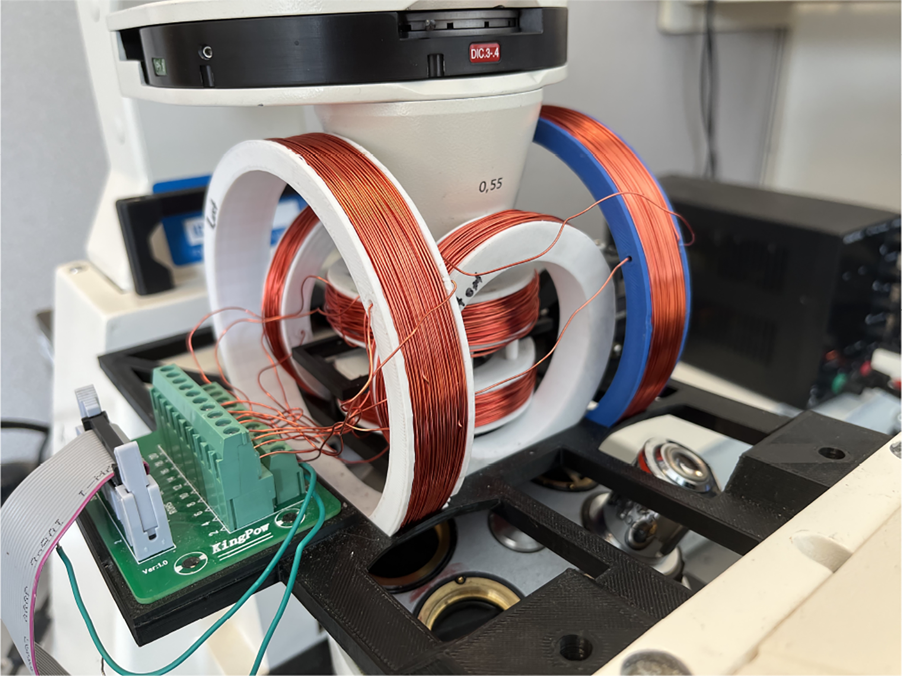
Experimental setup
Fig. 2:
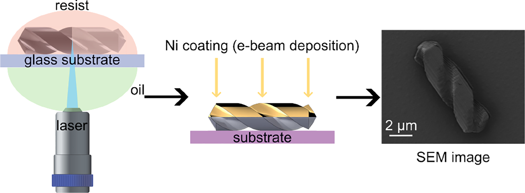
Fabrication process of proposed helical microrobots
B. Hardware Design and Experiment Setup
The microrobots were controlled using the Helmholtz coils system. It is mounted on a Zeiss Axiovert 200 M inverted microscope, as illustrated in Fig. 3. We modeled the coils system and stage in SolidWorks and printed them using 3D printing with PLA+ as the material. The system incorporates three pairs of orthogonal Helmholtz coils, each of varying dimensions, wound with 24 AWG copper wire. The small and medium-sized coils feature roughly 360 turns, whereas the largest coil has around 260 turns.
Fig. 1 provides a comprehensive system overview. The coils are actuated by an independent Arduino control module, which is composed of an Arduino Mega 2560, multiple H-Bridge Drivers, and a dedicated power supply. The Arduino retrieves the signal via the personal computer (PC) USB port. For visualizing on a microscopic scale, we employed a FLIR BFS-U3–50S5C-C camera connected to the PC using a USB interface.
Once the magnetic field is turned on, a three-dimensional (3D) magnetic field coordinate system has been established, as demonstrated in Fig. 4. The components of the joint magnetic field, namely Bx, By, and Bz, are provided by three corresponding pairs of Helmholtz coils. To drive the helical microrobot to roll, we must implement a rotating magnetic field, which in turn applies a torque to the located microrobot, as illustrated by
| (1) |
where μ represents the magnetic moment. We can utilize two angles, α and θ, to describe the direction of the rotation axis within the 3D space. The correlation between these two angles and the magnetic field components can be expressed as
| (2) |
To generate the rotating magnetic field, sinusoidal current signals are applied to each coil pair. Each resultant magnetic field component can be derived using Equation (3) from our previous research [38]
| (3) |
where B0 indicates the initial magnetic field, which is determined by the magnitude of the current, and ω represents the rotation frequency.
Fig. 4:
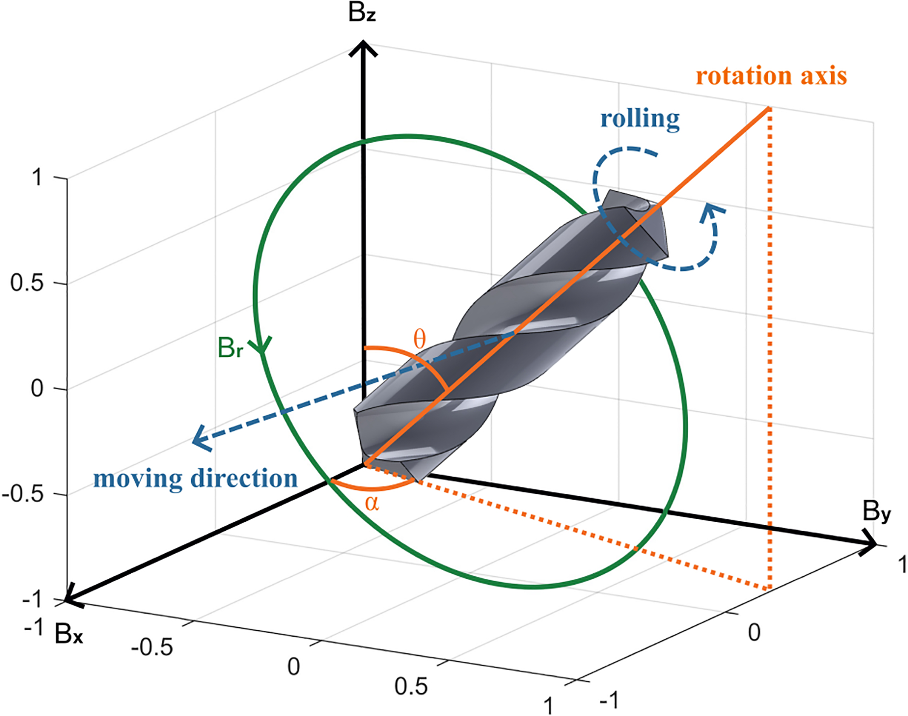
Helical microrobot rolling actuation
C. Cell Culture and Maintenance
Chinese Hamster Ovary (CHO) cells were used for the cell patterning experiments. Cells were maintained in Dulbecco’s Modified Essential Medium/Nutrient Mixture F-12 (DMEM/F-12, Gibco, BenchStable, USA) supplemented with 10% Fetal Bovine Serum and 1% penicillin-streptomycin at 37 °C in a humidified atmosphere with 5% CO2. Cells were used before they reached 90% confluency and after the third passage. Before experiments, cells were washed with Dulbecco’s phosphate-buffered saline (DPBS) (Gibco, BenchStable, USA) and trypsinized to detach cells from the culture flask. For in vitro cytotoxicity, trypan blue staining was performed to identify the number of live/dead cells after treatment. Cells were cultured overnight under standard culture conditions with the microrobots in a 6-well plate (Costar, Corning, USA) 1 × 10⁵ cells/ml per well. Next, the media was centrifuged and resuspended in Phosphate Buffer Saline (PBS) (Gibco, BenchStable, USA). A 10 μl of cell suspension was mixed with an equal volume of 0.4% trypan blue, and cells were counted in a cell counter (Nexcelom Cellometer Vision Trio Cell Profiler, USA). Cell morphology after staining was observed under an optical microscope (ZOE Fluorescent Cell Imager, USA). In addition, cell viability after microrobot actuation was determined on CHO cells. Subsequently, cells were cultured for 24 hours in a humidified cell culture incubator at 37 °C with 5% CO2 after microrobot actuation under a constant magnetic field. The cells were observed under the optical microscope directly after and 24 hours after the actuation.
III. Experimental RESULTS AND Discussion
A. Open Loop Control
We employ a wireless controller to control the movement direction of the microrobot. The joystick on this controller offers a full 360° rotation, allowing for directional control. When the joystick is manipulated in a specific direction, it sends a corresponding signal to the control module, which in turn adjusts the current supplied to the coil. Consequently, the direction of the rotating magnetic field changes, enabling the microrobot to move in the commanded direction. The magnitude of the magnetic field can also be modulated by the extent to which the joystick is pushed. According to Equation 1, this results in increased torque, a feature that can be useful in scenarios where the helical microrobots are hindered from rolling and become stuck in certain locations. The velocity of the helical microrobot’s rolling motion primarily hinges on the rotating magnetic field’s frequency (ω). An increased frequency directly results in a faster rolling motion and a higher velocity for the microrobot. Based on our computational calculations, at a frequency of 4 Hz, the microrobot can attain a locomotion speed of approximately 22 μm/s. We can change the frequency value through our interface during the experiment.
B. Cell Patterning
We used helical microrobots to move the cells to assemble specific shapes by applying the open loop control. Fig. 5(A) and supporting video show that microrobots navigate to the target CHO cells and push and leave them to the end-point. Based on this propulsion mechanism, cells were arranged in “T” and “U” patterns, respectively. The “T” and “U” patterns comprise 5 CHO cells each. Forming the “T” pattern required a total of 190 seconds, while the “U” pattern took 270 seconds. The longer duration for the latter is attributable to the microfluidic drifts experienced during the experiment, which affected the cell arrangement and fixation process. The results indicate the flexibility and controllability of cell manipulation. We did this by using the joystick of a PS wireless controller. Cell manipulation via microrobots is great for showing magnetic manipulation and control. There are studies in which authors used micro holder-headed helical-shaped microrobots to grasp the microbeads [39] to show the manipulation efficiency. On the other hand, there are some studies to make similar patterns with microbeads and NIH-3T3 cell aggregates via non-spherical shape magnetic microrobots [40].
Fig. 5:
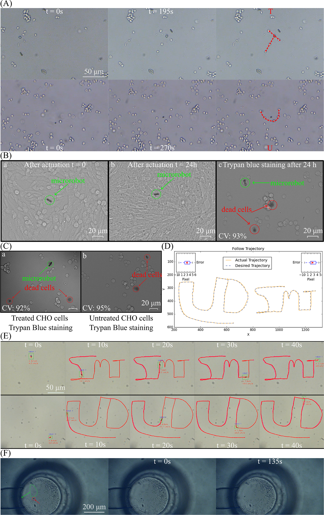
Helical microrobots experiment results. A. Helical microrobot arranges cells into patterns. B. Images of CHO cells immediately after (a) and 24 hours after (b) microrobot actuation. Cell viability was 93% after actuation. (c). Dead cells are stained and shown in red circles. CV represents cell viability. C. Images of microrobot-treated (a) and untreated (b) CHO cells. Cell viability was 92% after microrobot treatment. Dead cells are stained and shown in red circles. CV represents cell viability. E. Helical microrobot follows two different trajectories. D. The comparison between desired and actual. F. Two helical microrobots moving multiple cells in a microchannel.
C. Cell Viability
Assessing the vitality of cells is vital when considering the various uses of microrobots in cellular applications. This study determined cell viability on CHO cells via trypan blue staining after microrobot actuation.
Fig. 5(B) shows the images of the CHO cells right after and 24 hours after the microrobot treatment. It is clearly seen that the cell morphology was intact and cell proliferation was unaffected. Also, cell viability was 93% after 24 hours of actuation. Trypan blue staining was also performed to get the quantitative cell viability for overnight incubation with microrobots. In Fig 5(C), the live/dead cell ratios for both control and microrobot-treated cells were given. Cellular viability and cell morphology were similar, also there were no dead cells which are in contact with the microrobots determined. Considering these results, the microrobots exhibited biocompatibility, making them suitable for further potential applications both in vitro and in vivo.
D. Closed Loop Control
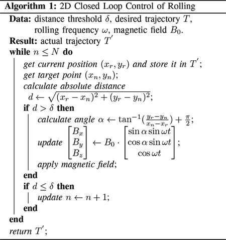
A closed-loop control system was implemented to achieve trajectory tracking, with the primary objective of guiding the microrobots along a specific path from the origin to the destination. A particular microrobot is selected to be tracked along the trajectory in this system. The user defines the trajectory on the computer screen based on the image captured by the camera. The system extracts the Cartesian coordinates of both the desired trajectory: which can be stored in an array T = [(x1, y1), (x2, y2), …, (xN, yN)], and the chosen microrobot (xr, yr). The algorithm outlined in Algorithm 1 is employed to assess how accurately the microrobot follows the prescribed trajectory by comparing the actual and desired paths with a predefined distance threshold δ. The algorithm automatically computes the angles governing the magnetic field, as described in Equation (2), and illustrated in Fig. 4. In this experimental setup, the closed-loop operates in a 2D environment, with θ = 90°, and α determined by the algorithm based on the current and desired positions of the microrobot. Subsequently, a magnetic field is applied to direct the motion of the microrobot. The algorithm aims to reduce the distance between the current and desired positions within the predefined threshold at each time step.
To assess the performance of the closed-loop control system, two trajectories labeled “UD” and “SMT” were tracked. The user manually drew these trajectories, and as shown in Fig. 5(D), the microrobot followed the prescribed path with an error smaller than 5 pixels (around 2.5 μm) in both cases. Fig. 5(E) and supporting video present actual footage of the microrobot successfully completing the trajectory. The microrobot accomplished the entire path within 40 seconds, solely propelled by the rolling magnetic field generated using Algorithm 1. These results hold significant promise for the field of helical microrobots, as they demonstrate the feasibility of guiding a microrobot along a desired trajectory for various applications. Moreover, in light of the findings presented in the preceding subsection, helical microrobots exhibit the potential for performing cell manipulation in closed-loop environments, enabling automated applications.
E. Multiple Cells
To demonstrate the bio-application of our microrobots, we used these helical microrobots for manipulating multiple cells in microchannels that mimic blood vessels. Two 10 μm microrobots could drive, push, and drop particular CHO cells. The microchannels were bought from Darwin Microfluidics and were 20 μm wide and 20 μm deep. CHO cells were put in the inlet part of the micro-channel to mimic crowded cell environments. Helical microrobots could push the cells from the inlet into the micro-channel, as shown in Fig 5(F) and supporting video. Open loop control moved a group of cells from the inlet to the micro-channel in 135 seconds.
IV. Conclusion
In this study, we successfully demonstrated helical microrobots’ cellular manipulation and path-tracking capabilities under open-loop and closed-loop control modes, respectively. The results highlight helical microrobots’ potential for robust cellular manipulation in biological and medical applications. The ability to manipulate cells using magnetic actuation showcases the versatility and maneuverability of the microrobots, as evidenced by successful cell patterning. Furthermore, the path-tracking experiments conducted with rolling magnetic fields demonstrate the effectiveness of the microrobots in a liquid environment, enabling them to accurately reach a target by following a predetermined trajectory. This capability allows precise navigation and targeted delivery in biomedical systems. Aside from the two control modes, we have also demonstrated the microrobot’s ability to operate in densely populated cell environments like a microtube. This characteristic is particularly relevant for various biological and biomedical systems.
Looking ahead, several interesting directions can be followed for future research. These include exploring different tasks of cell manipulation under closed-loop control, utilizing the microrobots for drug delivery applications in both control modes, and investigating the effects on the microrobot’s motility when multiple microrobots are stuck together. The microrobots presented in this work hold great potential for researchers and scientists working in the micro and nano realms. Their precise manipulation capabilities and movement offer numerous opportunities for high-precision tasks and advancements in various fields.
Acknowledgements
The authors gratefully acknowledge Dr. Ron Weiss from MIT for his help with the CHO cells. MÇK and AEW were supported by the Engineering Research Centers Program of the National Science Foundation under NSF Cooperative Agreement No. EEC-1647837 (CELL-MET). This work was supported by the National Science Foundation under grant GCR 2219101 and the National Health Institute under grant 1R35GM147451. This project was also supported by a grant from the National Institute of General Medical Sciences - NIGMS (5P20GM109021-07) from the National Institutes of Health and the State of Delaware.
References
- [1].Taylor RH, “A perspective on medical robotics,” Proceedings of the IEEE, vol. 94, no. 9, pp. 1652–1664, 2006. [Google Scholar]
- [2].García S, Strüber D, Brugali D, Berger T, and Pelliccione P, “Robotics software engineering: A perspective from the service robotics domain,” in Proceedings of the 28th ACM Joint Meeting on European Software Engineering Conference and Symposium on the Foundations of Software Engineering, 2020, pp. 593–604. [Google Scholar]
- [3].Ahmad B, Gauthier M, Laurent GJ, and Bolopion A, “Mobile microrobots for in vitro biomedical applications: A survey,” IEEE Transactions on Robotics, vol. 38, no. 1, pp. 646–663, 2021. [Google Scholar]
- [4].Shah ZH, Wu B, and Das S, “Multistimuli-responsive microrobots: A comprehensive review,” Frontiers in Robotics and AI, vol. 9, p. 1027415, 2022. [DOI] [PMC free article] [PubMed] [Google Scholar]
- [5].Khomambazari SM, Yusuf M, Esmaeilkhanian A, Zarei R, Hojjati M, Sharifianjazi F, and Arabuli L, “Review of bubble and magnetically driven catalytic micro/nanomotors: Fabrication and characterization,” Journal of Composites and Compounds, vol. 4, no. 13, pp. 220–231, 2022. [Google Scholar]
- [6].Safdar M, Khan SU, and Jänis J, “Progress toward catalytic micro- and nanomotors for biomedical and environmental applications,” Advanced Materials, vol. 30, no. 24, p. 1703660, 2018. [DOI] [PubMed] [Google Scholar]
- [7].Fusi AD, Li Y, Llopis-Lorente A, Patiño T, van Hest JC, and Abdelmohsen LK, “Achieving control in micro-/nanomotor mobility,” Angewandte Chemie, vol. 135, no. 5, p. e202214754, 2023. [DOI] [PMC free article] [PubMed] [Google Scholar]
- [8].Ma X, Hahn K, and Sanchez S, “Catalytic mesoporous janus nanomotors for active cargo delivery,” Journal of the American Chemical Society, vol. 137, no. 15, pp. 4976–4979, 2015. [DOI] [PMC free article] [PubMed] [Google Scholar]
- [9].Mallick S, Abouomar R, Rivas D, Sokolich M, Kirmizitas FC, Dutta A, and Das S, “Doxorubicin-loaded microrobots for targeted drug delivery and anticancer therapy.” Advanced Healthcare Materials, pp. e2 300 939–e2 300 939, 2023. [DOI] [PMC free article] [PubMed] [Google Scholar]
- [10].Li J, Li X, Luo T, Wang R, Liu C, Chen S, Li D, Yue J, Cheng S.-h., and Sun D, “Development of a magnetic microrobot for carrying and delivering targeted cells,” Science robotics, vol. 3, no. 19, p. eaat8829, 2018. [DOI] [PubMed] [Google Scholar]
- [11].Rivas D, Mallick S, Sokolich M, and Das S, “Cellular manipulation using rolling microrobots,” in 2022 International Conference on Manipulation, Automation and Robotics at Small Scales (MARSS). IEEE, 2022, pp. 1–6. [DOI] [PMC free article] [PubMed] [Google Scholar]
- [12].Rahman MM, Garudadri T, and Das S, “Role of surface tension in microrobot penetration in membranes,” in 2022 International Conference on Manipulation, Automation and Robotics at Small Scales (MARSS). IEEE, 2022, pp. 1–6. [DOI] [PMC free article] [PubMed] [Google Scholar]
- [13].Sokolich M, Rivas D, Shah ZH, and Das S, “Automated control of catalytic janus micromotors,” MRS Advances, pp. 1–5, 2023.37362909 [Google Scholar]
- [14].Das S, Garg A, Campbell AI, Howse J, Sen A, Velegol D, Golestanian R, and Ebbens SJ, “Boundaries can steer active janus spheres,” Nature communications, vol. 6, no. 1, p. 8999, 2015. [DOI] [PMC free article] [PubMed] [Google Scholar]
- [15].Shah ZH, Sockolich M, Rivas D, and Das S, “Fabrication and open-loop control of three-lobed nonspherical janus microrobots,” MRS Advances, pp. 1–5, 2023. [DOI] [PMC free article] [PubMed] [Google Scholar]
- [16].Vizsnyiczai G, Frangipane G, Maggi C, Saglimbeni F, Bianchi S, and Di Leonardo R, “Light controlled 3d micromotors powered by bacteria,” Nature communications, vol. 8, no. 1, p. 15974, 2017. [DOI] [PMC free article] [PubMed] [Google Scholar]
- [17].Ren L, Nama N, McNeill JM, Soto F, Yan Z, Liu W, Wang W, Wang J, and Mallouk TE, “3d steerable, acoustically powered microswimmers for single-particle manipulation,” Science advances, vol. 5, no. 10, p. eaax3084, 2019. [DOI] [PMC free article] [PubMed] [Google Scholar]
- [18].Sun Y, Pan R, Chen Y, Wang Y, Sun L, Wang N, Ma X, and Wang GP, “Efficient preparation of a magnetic helical carbon nanomotor for targeted anticancer drug delivery,” ACS Nanoscience Au, 2022. [DOI] [PMC free article] [PubMed] [Google Scholar]
- [19].Das S, Hunter EE, DeLateur NA, Steager EB, Weiss R, and Kumar V, “Cellular expression through morphogen delivery by light activated magnetic microrobots,” Journal of Micro-Bio Robotics, vol. 15, pp. 79–90, 2019. [Google Scholar]
- [20].——, “Controlled delivery of signaling molecules using magnetic microrobots,” in 2018 international conference on manipulation, automation and robotics at small scales (MARSS). IEEE, 2018, pp. 1–5. [Google Scholar]
- [21].Das S, Steager EB, Stebe KJ, and Kumar V, “Simultaneous control of spherical microrobots using catalytic and magnetic actuation,” in 2017 International Conference on Manipulation, Automation and Robotics at Small Scales (MARSS). IEEE, 2017, pp. 1–6. [Google Scholar]
- [22].Beaver LE, Wu B, Das S, and Malikopoulos AA, “A first-order approach to model simultaneous control of multiple microrobots,” in 2022 International Conference on Manipulation, Automation and Robotics at Small Scales (MARSS). IEEE, 2022, pp. 1–7. [DOI] [PMC free article] [PubMed] [Google Scholar]
- [23].Peyer KE, Zhang L, and Nelson BJ, “Bio-inspired magnetic swimming microrobots for biomedical applications,” Nanoscale, vol. 5, no. 4, pp. 1259–1272, 2013. [DOI] [PubMed] [Google Scholar]
- [24].Zhang L, Abbott JJ, Dong L, Kratochvil BE, Bell D, and Nelson BJ, “Artificial bacterial flagella: Fabrication and magnetic control,” Applied Physics Letters, vol. 94, no. 6, p. 064107, 2009. [Google Scholar]
- [25].Aghakhani A, Yasa O, Wrede P, and Sitti M, “Acoustically powered surface-slipping mobile microrobots,” Proceedings of the National Academy of Sciences, vol. 117, no. 7, pp. 3469–3477, 2020. [DOI] [PMC free article] [PubMed] [Google Scholar]
- [26].Rivas DP, Sokolich M, and Das s., “Spatial patterning of micromotor aggregation and flux,” ChemNanoMat, p. e202300225. [DOI] [PMC free article] [PubMed] [Google Scholar]
- [27].Guillotin B and Guillemot F, “Cell patterning technologies for organotypic tissue fabrication,” Trends in biotechnology, vol. 29, no. 4, pp. 183–190, 2011. [DOI] [PubMed] [Google Scholar]
- [28].Bi C, Niedert EE, Adam G, Lambert E, Solorio L, Goergen CJ, and Cappelleri DJ, “Tumbling magnetic microrobots for biomedical applications,” in 2019 International Conference on Manipulation, Automation and Robotics at Small Scales (MARSS). IEEE, 2019, pp. 1–6. [Google Scholar]
- [29].Jeon S, Kim S, Ha S, Lee S, Kim E, Kim SY, Park SH, Jeon JH, Kim SW, Moon C et al. , “Magnetically actuated microrobots as a platform for stem cell transplantation,” Science Robotics, vol. 4, no. 30, p. eaav4317, 2019. [DOI] [PubMed] [Google Scholar]
- [30].Steager EB, Selman Sakar M, Magee C, Kennedy M, Cowley A, and Kumar V, “Automated biomanipulation of single cells using magnetic microrobots,” The International Journal of Robotics Research, vol. 32, no. 3, pp. 346–359, 2013. [Google Scholar]
- [31].Wei T, Li J, Zheng L, Wang C, Li F, Tian H, and Sun D, “Development of a cell-loading microrobot with simultaneously improved degradability and mechanical strength for performing in vivo delivery tasks,” Advanced Intelligent Systems, vol. 3, no. 11, p. 2100052, 2021. [Google Scholar]
- [32].Wang Q, Tian Y, Du X, Ko H, Ip BYM, Leung TWH, Yu SCH, and Zhang L, “Magnetic navigation of collective cell microrobots in blood under ultrasound doppler imaging,” IEEE/ASME Transactions on Mechatronics, vol. 27, no. 5, pp. 3174–3185, 2021. [Google Scholar]
- [33].Pieters R, Lombriser S, Alvarez-Aguirre A, and Nelson BJ, “Model predictive control of a magnetically guided rolling microrobot,” IEEE Robotics and Automation Letters, vol. 1, no. 1, pp. 455–460, 2016. [Google Scholar]
- [34].Kim SJ, Jeon SM, Nam JK, and Jang GH, “Closed-loop control of a self-positioning and rolling magnetic microrobot on 3d thin surfaces using biplane imaging,” IEEE Transactions on Magnetics, vol. 50, no. 11, pp. 1–4, 2014. [Google Scholar]
- [35].Nguyen KT, Go G, Jin Z, Darmawan BA, Yoo A, Kim S, Nan M, Lee SB, Kang B, Kim C-S et al. , “A magnetically guided self-rolled microrobot for targeted drug delivery, real-time x-ray imaging, and microrobot retrieval,” Advanced Healthcare Materials, vol. 10, no. 6, p. 2001681, 2021. [DOI] [PubMed] [Google Scholar]
- [36].Sun HCM, Liao P, Wei T, Zhang L, and Sun D, “Magnetically powered biodegradable microswimmers,” Micromachines, vol. 11, no. 4, p. 404, 2020. [DOI] [PMC free article] [PubMed] [Google Scholar]
- [37].Bachmann F, Bente K, Codutti A, and Faivre D, “Using shape diversity on the way to structure-function designs for magnetic micropropellers,” Physical Review Applied, vol. 11, no. 3, p. 034039, 2019. [Google Scholar]
- [38].Sokolich M, Rivas D, Yang Y, Duey M, and Das S, “Modmag: A modular magnetic micro-robotic manipulation device,” MethodsX, vol. 10, p. 102171, 2023. [DOI] [PMC free article] [PubMed] [Google Scholar]
- [39].Tottori S, Zhang L, Qiu F, Krawczyk KK, Franco-Obregón A, and Nelson BJ, “Magnetic helical micromachines: fabrication, controlled swimming, and cargo transport,” Advanced materials, vol. 24, no. 6, pp. 811–816, 2012. [DOI] [PubMed] [Google Scholar]
- [40].Li J, Wang H, Shi Q, Zheng Z, Cui J, Sun T, Ferraro P, Huang Q, and Fukuda T, “Biped walking of magnetic microrobot in oscillating field for indirect manipulation of non-magnetic objects,” IEEE Transactions on Nanotechnology, vol. 19, pp. 21–24, 2019. [Google Scholar]


