Abstract
This work aims to improve limited-angle (LA) cone beam computed tomography (CBCT) by developing deep learning (DL) methods for real clinical CBCT projection data, which is the first feasibility study of clinical-projection-data-based LA-CBCT, to the best of our knowledge. In radiation therapy (RT), CBCT is routinely used as the on-board imaging modality for patient setup. Compared to diagnostic CT, CBCT has a long acquisition time, e.g., 60 seconds for a full 360° rotation, which is subject to the motion artifact. Therefore, the LA-CBCT, if achievable, is of the great interest for the purpose of RT, for its proportionally reduced scanning time in addition to the radiation dose. However, LA-CBCT suffers from severe wedge artifacts and image distortions. Targeting at real clinical projection data, we have explored various DL methods such as image/data/hybrid-domain methods and finally developed a so-called Structure-Enhanced Attention Network (SEA-Net) method that has the best image quality from clinical projection data among the DL methods we have implemented. Specifically, the proposed SEA-Net employs a specialized structure enhancement sub-network to promote texture preservation. Based on the observation that the distribution of wedge artifacts in reconstruction images is non-uniform, the spatial attention module is utilized to emphasize the relevant regions while ignores the irrelevant ones, which leads to more accurate texture restoration.
Keywords: Limited angle CT, CBCT, structure enhancement, spatial attention, clinical projection data
I. Introduction
Cone-beam computed tomography (CBCT) is routinely used in radiation therapy (RT) to provide three-dimensional anatomical structures of patients, for patient setup before the RT delivery [1]. However, due to the long acquisition time (usually 1 min for a full 360° rotation), the CBCT image quality may be degraded with motion artifacts caused by patient or organ movements, which can lead to inaccurate dose delivery and replanning. Therefore, the reduction of CBCT scanning time is clinically significant.
Limited-angle CBCT (LA-CBCT) can accelerate the acquisition process proportionally by reducing the scanning angle range. However, LA-CBCT suffers from severe wedge artifacts and image distortions. This work aims to develop an LA-CBCT reconstruction method that will be practically feasible for real clinical projection data from the RT application. To reconstruct high-quality images from incomplete projection data, numerous algorithms have been developed for LA-CBCT reconstruction. Generally, these methods can be grouped into two categories: iterative (IR) algorithms, and deep learning (DL)-based methods.
Compared with analytical algorithms, iterative methods provide improved reconstruction images for LA-CBCT. Noticing the sparse property of image gradient, total variation (TV)-based methods have been investigated extensively. Specifically, Zeng et al. applied TV constraint for LA-CBCT to remove artifacts and against the noise [2]. Xie et al. additionally induced an -norm penalty on the projection data [3], which was able to restore the sharper edges. In addition, -norm [4] and non-local means [5] were applied to LA-CBCT. Although IR methods showed a superior performance in edge preservation and artifact reduction compared to analytical algorithms, they were limited by the following drawbacks. (1) careful selection of the hyperparameter values is necessary to guarantee the performance. (2) higher computational cost. (3) hand-crafted priors cannot describe the properties of wedge artifacts which leading to failure in reconstruction of high-quality images.
Recently, DL-based methods have been widely applied in the field of imaging restoration [6–8]. Due to the powerful representation capacity, deep neural networks can implicitly learn the intrinsical feature representation and outperform traditional reconstruction methods for medical imaging [9]. For CT reconstruction, DL-based methods can be classified into four categories: pre-processing methods, post-processing methods, dual-domain methods, and deep iterative methods. (a) Pre-processing methods employed convolutional neural networks (CNNs) to get the noiseless full-view projection data then it was then reconstructed with traditional methods. For example, Li et al. proposed a generative adversarial network (GAN) model to predict the missing projection data [10]. However, directly processing the projection data might cause secondary artifacts in reconstructed images. (b) Post-processing methods were concentrated on the image domain, which directly mapped the degraded images to high-quality versions via CNN models [11]. Particularly, post-processing can flexibly incorporate traditional techniques, such as wavelet, into CNN models to deliver improved results [12]. Due to the lack of data fidelity constraints, image-domain methods cannot guarantee the reliance on reconstructions in the worst cases [13] (c) Based on the previous two schemes, dual-domain methods aimed to promote image quality by jointly performing CNNs in sinogram space and image space. In general, due to more neural networks, dual-domain methods had superior performance than single-domain-based methods [14]. These methods can be easily applied to LA-CBCT [15] by decoupling the deep models and reconstruction procedures. But in LA-CBCT imaging, it is hard for the CNN model to inpaint the invisible projection within the three-dimensional space, which subsequently affects the performance of the image domain network. (d) Unlike the other three categories, deep iterative methods not only utilized neural networks but also employed the physical models [16]. Therefore, they can benefit from both advantages of deep networks and iterative methods which consequently led to outstanding results. For instance, Chen et al. proposed a new end-to-end unrolling framework named AirNet with the combination of proximal operator and CNN models for CT reconstruction and achieved remarkable performance than both IR methods and classical DL methods [17]. Hu et al. presented a framework that promotes the convergence property of the deep iterative method for LA-CBCT [18]. However, due to the complex iterative procedure, these methods need consume huge resources, which may limit the further applications.
Despite the widely used eep learning methods in CBCT reconstruction, most of which used simulated data or preclinical data, which may not work for real clinical data. In this paper, targeting at real clinical projection data, we explored various DL methods for LA-CBCT, including image/data/hybrid-domain methods, and finally arrived at an image-domain-based method termed Structure-Enhanced Attention Network (SEA-Net) for LA-CBCT reconstruction. This is the first comprehensive feasibility study of clinical-projection-data-based LA-CBCT to the best of our knowledge.
In summary, the main contributions of SEA-Net are as follows:
CNN models have shown great potential for image restoration, but they usually tend to blur the reconstruction results and miss some subtle structures [19]. Meanwhile, most of these methods only concentrate on promoting the reconstructed image itself, yet neglect some supplementary information contained in the images. Thus, they still have improvement room. To improve the utilization efficiency of image features, inspired by [20], we adopt a structure-enhanced network, which can additionally extract high-frequency components in CT images and feed them into the final reconstruction results, to boost the edge or texture preservation.
The distribution of wedge artifacts in limited-angle CT is significantly non-uniform yet classical CNNs treat every pixel equally in the global image space. Therefore, to discriminatively remove artifacts at different regions, a spatial attention module is employed [21] and generates more accurate tissue recovery.
All the experiments in this work are performed on the 3D real clinical projection data, and the corresponding results are comprehensively exhibited to reveal the performance of various methods in real LA-CBCT. We also evaluate the practical feasibility of LA-CBCT in radiation therapy, including patient setup accuracy and dose calculation accuracy.
In the rest of this paper, Section II will introduce the related works of limited-angle CT imaging. Section III gives a detailed description of the proposed SEA-Net. The reconstruction results and analysis are in Section IV. Section V will present the results of radiation therapy based on the reconstructed images. Discussions and conclusions are in Section VI.
II. Related Works
Among the currently used DL-based methods, post-processing and deep iterative are the most widely used strategies for limited-angle CT imaging.
The network architectures and loss functions are the key of pose-processing methods. Bigger network provides more powerful feature extraction ability while the specialized cost function can guide the direction of image generation. For example, to emphasize the image features, Zhou et al. merged multi-scale, dense connection, and dilated convolution to construct a complex CNN model (MSDD-CNN) [22]. Experiments showed that MSDD-CNN performed better in artifact correction and structure recovery. At the same time, to tackle the witness of the general CNN model in restoring tissue details, Hu et al. introduced GAN to boost minor structure preservation [23]. In general, these methods are simple and resource-saving and can be flexibly applied to different geometries without any modification. Nevertheless, most of these methods focus on image recovery itself [11, 24], ignoring some particular auxiliary information that benefits improving the reconstruction results [20, 25].
For the deep iterative methods, the core idea is to employ CNN models in replacing the hand-designed regularization terms. With the assistance of neural networks, deep iterative methods outperform traditional IR algorithms in various tasks [17, 26]. For instance, Cheng et al. jointly deployed learned regularizations in both the image domain and projection domain to comprehensively strengthen the interrelation between these two spaces [27]. Moreover, Wang et al. conducted multi-CNN models during the iterative processing to accelerate the convergence [28]. By considering the physical model, deep iterative methods could provide more reliable results. Generally, deep iterative methods could be divided into two categories: end-to-end optimization and multi-phase optimization. Due to memory limitations, it is hard for end-to-end optimization to be used in LA-CBCT (more details can be found in IV.H). Meanwhile, because of high computational costs [18], multi-phase optimization may be restricted in some time-sensitive applications.
III. Methodology
In this section, the overall framework of the proposed SEA-Net is introduced and then the details of each module and the loss function will be defined.
A. Structure-Enhanced Attention Network (SEA-Net)
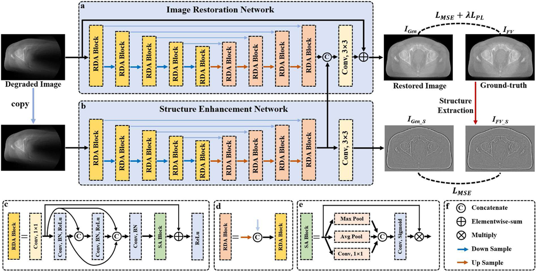
As mentioned above, post-processing methods are flexible and can be easily extended to various imaging tasks [15]. Therefore, after attempting various methods, we adopt the image-domain-based strategy for real clinical LA-CBCT reconstruction, whose overall framework is illustrated in Fig. 1. The proposed SEA-Net consists of two sub-networks: image restoration network (IR-Net) and the structure enhancement network (SE-Net), each of which utilizes the U-shape architecture to extract features, and the final generated result is obtained after fusing the features stored in IR-Net and SE-Net, respectively.
Fig. 1.
Overall framework of the proposed SEA-Net. (a) Image restoration sub-network. (b) Structure enhancement sub-network. (c)-(d) Residual dense attention blocks. (e) Spatial attention block. (f) Basic operation symbols.
B. IR-Net
Similar to typical image restoration CNNs [29], the IR-Net (as shown in Fig.1 (a)) adopts the encoder-decoder architecture and aims to map the degraded images into high-quality results directly. Specifically, the encoder stage has four downsample operations, which extract the low-level image features at the different scale levels. Correspondingly, the same number of upsampling operators are then applied to excavate high-level features and gradually restore the high-resolution results. To compensate for the missing information caused by downsampling, the skip connection that feeds the shallow features into subsequent layers is employed, which is a standard component of the U-shape network [24]. In addition, global residual learning is also induced to accelerate training convergence and improve performance [29]. Moreover, for better feature extraction, IR-Net designs a specialized residual dense attention (RDA) block, whose architecture could boost the accuracy of reconstruction results [26].
C. SE-Net
Although IR-Net is able to remove artifacts and restore most tissues, it still tends to generate over-smoothing results. Therefore, several works have been proposed to overcome the defects of CNNs in blurring images by adopting two-branch networks [20, 25]. Inspired by these methods, the structure enhancement sub-network is developed for better detail preservation (as demonstrated in Fig. 1(b)). Unlike IR-Net, the purpose of SE-Net is to recover high-quality texture information, which represents the details or edges of CT images. As reported in some methods [18, 25], the structural details of images can be obtained by Gaussian filter. Following these works, our structure extraction is formulated as follows.
| (1) |
where is the reconstructed image, stands for the convolution operator. represents the Gaussian filter kernel. To get the filter kernel , we first define , , . Then, . In this work, , , . As a result, can extract the tissue edges or small details as demonstrated in Fig. 1. It is worth noting that the operation is conducted on the ground truth image and guides the SE-Net to generate the high-quality structural features. More detailed information can be found in Eq. (3).
With the training process, the high-frequency structures of images can be stored in SE-Net. Next, the feature maps obtained from the last RDA block in SE-Net are concatenated with the IR-Net to increase the diversity of feature representation. The final improved reconstruction result can be produced based on these fused features.
D. Residual Dense Attention (RDA) Block
To further improve the representation capacity of the proposed SEA-Net, we design the residual dense attention (RDA) block (as depicted in Fig. 1 (c)). First, a convolutional layer with filter kernel size of 1×1 is used to change the input feature maps to a fixed channel number . Next, the dense connection is conducted to promote the information flow by linking every layer with each other [24]. Each layer consists of convolution, batch normalization, and ReLU operations. Particularly, the convolution kernel is set to 3×3 and the feature number is also . Besides, a spatial attention block is embedded before the last activation function to discriminate where regions are more important for artifact removal and tissue restoration [26]. Last, RDA employs local residual learning to avoid gradient vanishing or exploding [30]. The convolution numbers of RDA blocks at different scale levels are , , , , and , respectively. In our work, the is 16 and 8 in IR-Net and SE-Net.
E. Spatial Attention (SA) Block
As shown in Fig. 1, the wedge artifacts of degraded images in limited-angle CT are distributed non-uniformly, which implies that some regions should receive more attention. However, the standard convolutional layer treats the spatial features equally. To overcome this issue, spatial attention (SA) is developed to evaluate the importance of different image locations and lead to remarkable performance in various tasks [21, 26]. In our work, the proposed SA block is modified from [21]. For the input feature maps, we first perform max pooling, average pooling, and convolutional layer along the channel dimension to obtain the compressed feature maps , and , which stand for three types of responses to the spatial areas. Then, the sigmoid function is applied to transform the linear combination of , , and to a probability volume , which indicates the relevance of different areas to the imaging task. Finally, the calibration features are achieved by . With the embedding of SA blocks, the SEA-Net can emphasize the important spatial regions and ignore irrelevant ones.
F. Perceptual Loss
In image restoration, and losses are the most commonly used cost functions that directly measure the difference between two images pixel-by-pixel. They perform well in smooth regions but often miss details in textured areas. Instead of pixel-wise evaluation, perceptual loss assesses the similarity of two objects in the feature space and leads to visually improved results than or loss [18, 31]. The perceptual loss can be written as:
| (2) |
where is the reference image, is the generated image, denotes the feature extractor. In our work, the pre-trained VGG-16 [32] is utilized as the feature extractor. Specifically, the output of 2nd, 4th, 6th, 9th and 12th convolutional layers are selected as feature extractor .
G. Loss Function
The cost function of the proposed SEA-Net is formulated as follows.
| (3) |
As shown in Fig.1, is the reference image reconstructed by the FDK (Feldkamp-Davis-Kress) method from full-view projection data, is the hyperparameter to balance different terms, , and are the outputs of IR-Net and SE-Net, respectively.
IV. Experiments
In this section, the performance of different reconstruction methods applied to LA-CBCT will be evaluated. All the experiments were performed on real clinical projection data.
A. Comparison Methods & Evaluation Metrics
All the DL-based methods were implemented using the TensorFlow framework on an NVIDIA GeForce RTX 3090 with 24G memory. The hyperparameter in Eq. (3) was set to 0.001. The proposed SEA-Net was optimized by the Adam algorithm. The learning rate was initially set to 10−3 and decreased to 10−5. And the training epoch was 50. The mini-batch size was 4. The size of the input image in the training and testing phases is both 512×512. Specifically, the codes of SEA-Net are available at https://github.com/lonelyatu/SEA-Net. To validate the performance of SEA-Net, the FDK algorithm, TV, DDNet [24], DCAR [33], FED-INet [18], and modified Sam’Net [16] were treated as comparisons. Specifically, DDNet and FED-INet were image-domain-based methods and both of them adopted DenseNet as their backbones. The difference was that FED-INet utilized a more complex loss function which led to better performance. DCAR first employed the CNN model to obtain the missing projection data and then applied the IR method to improve image quality. To compare with advanced reconstruction algorithms (i.e. dual-domain-based methods and deep iterative methods), Sam’Ne was modified to apply LA-CBCT, which was an unrolling method proposed for fan-beam CT and represented the state-of-the-art. Besides, the root-mean-square error (RMSE), peak signal-to-noise ratio (PSNR), and structural similarity index (SSIM) were adopted to evaluate different reconstruction methods.
B. Clinical Data Acquisition
In this work, all the CBCT projection data was acquired during radiation therapy cancer treatments on the Varian TrueBeam linacs (Varian Medical Systems, Palo Alto, California, USA) at the Department of Radiation Oncology of the University of Kansas Medical Center, as part of standard image-guided radiation therapy workflow for patient setup.
Then, the anonymized raw CBCT projection data were retrospectively analyzed under the approved IRB protocol. The imaging geometry is as follows. The source-to-axis distance was 100 cm and the source-to-detector was 150 cm. The detector had 512×384 elements and each of them represented an area of 0.766 mm2. To increase the field-of-view (FOV), the half-fan mode was applied with the detector offset 160 mm. For each scan, 720 views were collected from 360° as the full-view projection data with the tube voltage of 125 kVp and tube current-time product of 1072–1074 mAs.
The reference images were reconstructed by the FDK algorithm from the full-sampled projection data. Fast parallel algorithms were used for on-the-fly calculation of the X-ray projections and backprojections [34, 35]. The reconstructed volume had the size of 512×512×250, and every voxel was 1×1×0.65 mm3. Finally, 112500 images were used (90 patients) in this study, i.e., 102500 images for training, 5000 images for validation, and 5000 images for testing.
C. Experimental Results
Table I lists the quantitative evaluations of different reconstruction methods with three scanning ranges: [0°, 180°], [0°, 135°], and [0°, 90°]. Compared to the FDK algorithm, all the DL-based methods make significant improvements. Particularly, learning from a large number of paired training samples, DDNet can directly map degraded images to high-quality results. DCAR is an iterative method that first takes the DDNet to predict the missing projection data and then integrates it with the available measurement data to get the full-view projections. The final reconstruction images can be obtained by the TV method from the complete projection data. As reported in early works [18, 33], DCAR outperforms DDNet in all evaluation indicators when the scanning ranges are 150° and 110°. However, as shown in Table I, the DCAR is always worse than DDNet in our experiment. The reason may be that the data consistency in DCAR is corrupted by the detector shift of half-fan mode. Benefiting from the enhanced perceptual loss, FED-INet achieves superior scores than other comparison methods in terms of RMSE and PSNR. However, it leads to decreased SSIMs in some cases. It is worth noting that the proposed method produces the best evaluations, which means the generated results provided by SEA-Net are closest to the reference image both in pixel values and structural features.
Table I.
Quantitative Evaluations Of Different Reconstruction Methods For The Clinical Dataset.
| Range | Metric | FDK | DDNet | DCAR | FED-INet | SEA-Net |
|---|---|---|---|---|---|---|
|
| ||||||
| [0°, 180°] | RMSE(10−4) PSNR SSIM |
15.86 17.00 0.7457 |
2.61 32.79 0.9082 |
2.67 32.62 0.9071 |
2.47 33.30 0.9093 |
2.38
33.61 0.9131 |
|
|
||||||
| [0°, 135°] | RMSE(10−4) PSNR SSIM |
18.87 15.48 0.6800 |
2.92 31.80 0.8797 |
2.96 31.69 0.8782 |
2.88 31.94 0.8739 |
2.78
32.25 0.8829 |
|
|
||||||
| [0°, 90°] | RMSE(10−4) PSNR SSIM |
20.75 14.66 0.6458 |
3.44 30.39 0.8573 |
3.46 30.34 0.8550 |
3.26 30.87 0.8517 |
3.17
31.13 0.8613 |
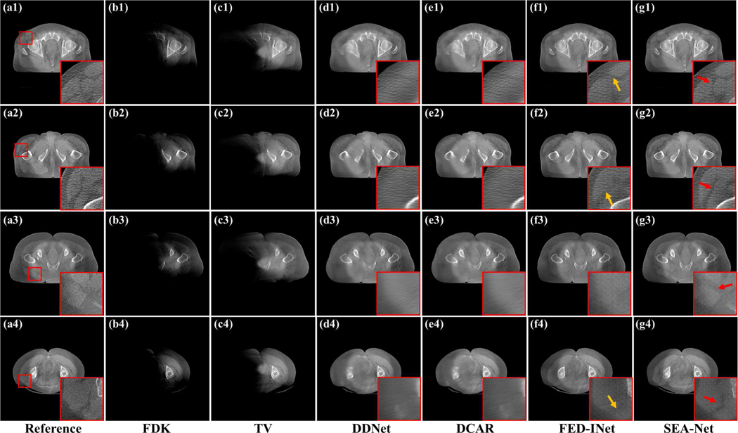
Fig. 2 demonstrates the reconstructed results with the scanning range [0°, 180°] to explore the visual performance of different methods on clinical data. Due to the projection missing, most anatomical structures reconstructed from the FDK algorithm are lost. Although it costs more time and hardware resources, TV only brings little improvement compared to FDK. This is because heuristic methods cannot provide an effective constraint on the reconstruction images when dealing with the LA-CBCT problem. In contrast to the poor results of FDK and TV, DL-based methods significantly promote the reconstruction images. From Fig. 2(d1)–(e4), it can be seen that DDNet and DCAR methods can restore most of the structural information, including bones and body contours. Unfortunately, as mentioned above, DDNet and DCAR produce too blurred regions. With the minimization of the distance between the reference image and generated ones in feature space, FED-INet can provide more visually improved results by preserving more details and recovering accurate tissues (as pointed by yellow arrows in Fig. 2(f1)–(f4)). Last, the proposed SEA-Net leads to the most impressive reconstructions in that it can restore subtle structures and fine edges (as noticed by red arrows in Fig. 2(g1)–(g4)).
Fig. 2.
Reconstructed images and the zoomed region-of-interests (ROIs) of different methods with the scanning range [0°,180°]. (a1)-(a4) Reference images reconstructed by FDK algorithm from full-sampled projection data. (b1)-(b4) Images reconstructed by FDK algorithm. (c1)-(c4) Images reconstructed by TV method. (d1)-(d4) Images provided by DDNet method. (e1)-(e4) Images provided by DCAR method. (f1)-(f4) Images provided by FED-INet method. (g1)-(g4) Images provided by SEA-Net method. The display window is [0.003, 0.008].
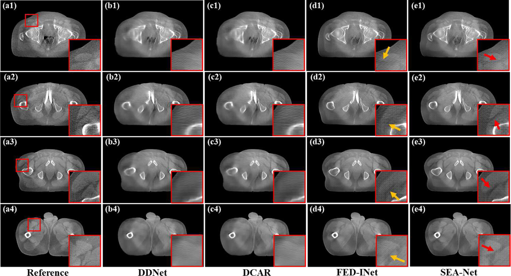
Fig. 3 shows the reconstructed images of different methods with a smaller scanning range [0°, 135°]. In this condition, DDNet and DCAR can only produce blurred organ margins and most diagnostic information is missed. From the yellow arrows in Fig. 3(d1)–(d4), it can be seen that FED-INet generates clear tissue contours and shape edges and most anatomic structures are restored. Compared to FED-INet, the proposed method further promote the results in minor details preservation (as illustrated by red arrows in Fig. 3(e1)–(e4)).
Fig. 3.
Reconstructed images and the zoomed ROIs of different methods with the scanning range [0°,135°]. (a1)-(a4) Reference images reconstructed by FDK algorithm from full-sampled projection data. (b1)-(b4) Images provided by DDNet method. (c1)-(c4) Images provided by DCAR method. (d1)-(d4) Images provided by FED-INet method. (e1)-(e4) Images provided by SEA-Net method. The display window is [0.003, 0.008].
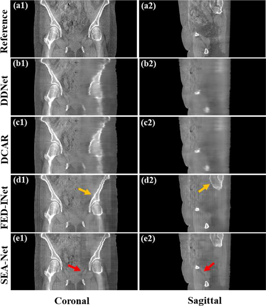
To comprehensively probe the visual performance of different methods, the selected coronal and sagittal views reconstructed from the scanning range [0°, 90°] are given in Fig. 4. Similar to the observations in Figs. (2)-(3), FED-INet and SEA-Net perform better in bone restoration and detail preservation. However, the obvious checkerboard artifacts are induced in FED-INet and SEA-Net results because of the usage of perceptual loss [18], which might bring negative effects on the subsequent tasks.
Fig. 4.
Coronal and sagittal views of different methods with the scanning range [0°, 90°]. (a1)-(e1) Coronal images. (a2)-(e2) Sagittal images. (a1)-(a2) Reference images reconstructed by FDK algorithm from full-sampled projection data. (b1)-(b2) Images provided by DDNet method. (c1)-(c2) Images provided by DCAR method. (d1)-(d2) Images provided by FED-INet method. (e1)-(e2) Images provided by SEA-Net method. The display window is [0.003, 0.008].
D. Ablation Study
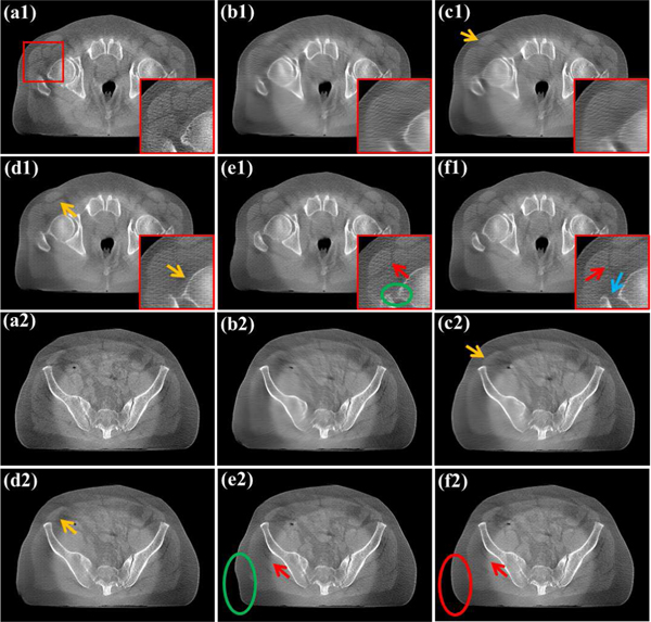
In this part, an ablation study was conducted to validate the different modules used in SEA-Net. All the results were conducted on 1000 images reconstructed with the scanning range [0°, 180°]. The IR-Net with MSE loss was taken as the baseline model, then the SE-Net was incorporated into the IR-Net to make the first comparison method. Meanwhile, the perceptual loss (PL) was added to the baseline model to construct the second comparison method. Next, the SE-Net was incorporated into the second comparison model to establish the third comparison method. Last, the spatial attention module was introduced based on the third comparison model to build the fourth model, i.e., SEA-Net.
Table II presents the quantitative evaluations for the progressive ablation study. It can be seen that the PL and SE-Net only bring a little improvement over the baseline model in RMSE, PSNR and SSIM. With the assistance of the spatial attention module, SEA-Net gains the best performance in all evaluations, which means that spatial attention can indeed boost the accuracy of reconstruction images.
Table II.
Quantitative Evaluations For The Progressive Ablation Study.
| Metric | Baseline | +SE-Net | +PL | +SE-Net+PL | SEA-Net |
|---|---|---|---|---|---|
|
| |||||
| RMSE(10−4) | 2.82 | 2.81 | 2.82 | 2.80 | 2.68 |
| PSNR | 32.80 | 32.88 | 32.83 | 32.85 | 33.22 |
| SSIM | 0.9044 | 0.9085 | 0.9053 | 0.9099 | 0.9132 |
Fig. 5 demonstrates the reconstruction images of different modules. The baseline model adopts a similar architecture to the DDNet, therefore, it generates the same over-smoothing results as observed in Figs. 2–4. Due to the additional structure image extraction, the first comparison model brings sharper tissues boundary (as illustrated by yellow arrows in Fig. 5(c1)(c2)) After employing PL, the second comparison method improves the baseline model by reconstructing clear tissue edges (as pointed with yellow arrows in Fig. 5(d1)(d2)), which states the effectiveness of PL [18]. Further, from areas indicated by red arrows in Fig. 5(e1)(e2), the third comparison model is able to restore more subtle details than the previous two comparisons. This indicates that SE-Net and PL are complementary and can collaboratively promote edge recovery. Although the PL and SE-Net have little effect on the quantitative evaluation, they can improve the reconstruction results in structure preservation. Last, by applying spatial attention, SEA-Net can distinguish which region is more relevant to getting high-quality results. Thus, SEA-Net has a superior performance in preserving spatial textures than previous models. Specifically, it can restore more accurate femoral head structures (as shown by the green ellipse and blue arrow in Fig. 5(e1)(f1)) and body contours (as marked by the green ellipse and red ellipse in Fig. 5(e2)(f2)).
Fig. 5.
Reconstructed results of different modules with the scanning range [0°, 180°]. (a1)-(a2) Reference images. (b1)-(b2) Baseline model results. (c1)-(c2) +SE-Net results. (d1)-(d2) +PL results. (e1)-(e2) +SE-Net+PL results. (f1)-(f2) SEA-Net results. The display window is [0.003, 0.008].
E. Hyperparameter Analysis
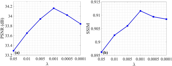
This section aims to explore how the hyperparameter in Eq. (3) affects the performance of SEA-Net. Fig. 6 illustrates the quantitative results with different values of from the scanning range [0°, 180°]. It can be noticed that bigger or smaller will lead to decreased evaluations, suggesting the importance of in balancing different loss functions. According to Fig. 6, the was finally set to 0.001 in all experiments.
Fig. 6.
Reconstructed image quality assessments with different .
F. Computational Cost
Table III lists the computational cost of different methods with 250 images reconstructed by the scanning angular range [0°, 180°]. Due to the complex iterative process, DCAR consumes much longer time than other methods. DDNet, FED-INet, and SEA-Net are post-processing algorithms and all of them can be executed within an appropriate time. Specifically, FED-INet and SEA-Net spend more time than DDNet because they have bigger network architectures.
Table III.
Computational Cost Of Different Methods (Unit: Second).
| Method | DDNet | DCAR | FED-INet | SEA-Net |
|---|---|---|---|---|
|
| ||||
| Time | 5.60 | 156.51 | 11.60 | 15.91 |
G. Convergence Analysis
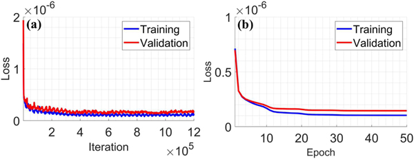
To explore the convergence of the proposed SEA-Net, Fig. 7 illustrates the cost function values (as defined in Eq. (3)) during the training process. It can be seen that the loss values of training and validation datasets decrease fast and stabilize after 20 epochs, which states the good convergence property of SEA-Net.
Fig. 7.
Loss function values vs. (a) iteration number and (b) epoch number.
H. Comparison of Advanced Methods
Currently, dual-domain-based methods and deep iterative methods are considered the most competitive algorithms for CT reconstruction [16, 18, 26, 30, 36, 37]. According to training fashions, these methods can be split into two groups: end-to-end training and multi-phase training.
Table IV shows the GPU memory requirements of several representative end-to-end training methods. It can be seen that all of these methods need high computational resources so they are usually performed on the fan-beam geometry. In this work, the reconstructed volume has a size of 512×512×250, and it is scarcely possible to implement end-to-end training methods with appropriate GPU memory.
Table IV.
GPU Memory Requirements Of Different End-To-End Training Methods.
The multi-phase training strategy decouples the deep network and image reconstruction, which means it is only required to store the related variables at the current step. Therefore, this scheme greatly lowers the GPU memory demands and can be applied to CBCT [30].
Comprehensively, to compare with advanced algorithms, we modify Sam’s Net [16] from end-to-end optimization to multi-phase processing for the application of LA-CBCT. Specifically, all the network architectures and training settings of modified Sam’s Net in this section are referred to [16]. Because Sam’s Net combines dual-domain processing and the deep iterative scheme, it can be regarded as a state-of-the-art technique.
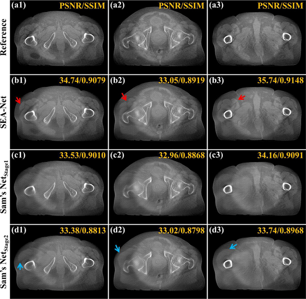
Fig. 8 exhibits the reconstruction results of different methods with the scanning range [0°, 180°]. From Fig. 8(c1)–(c3), it can be found that the first stage of Sam’s Net is able to suppress wedge artifacts and restore most tissues. However, as opposed to the observation in [16], the second stage in Sam’s Net fails to bring improvements in quantitative assessments based on the first stage. Meanwhile, the second stage leads to more clear edges, but most of them are fake structures (as pointed by blue arrows in Fig. 8(d1)–(d3)). Overall, the proposed SEA-Net performs better both in edge preservation and quantitative evaluations. So, although the dual-domain or deep iterative methods have been validated in various tasks [18, 30, 36], they may be unfit for our clinical projection data.
Fig. 8.
Reconstructed results of different methods with the scanning range [0°, 180°]. (a1)-(a3) Reference images reconstructed by FDK algorithm from full-sampled projection data. (b1)-(b3) Images provided by SEA-Net method. (c1)-(c3) Images provided by the first stage of Sam’s Net method. (d1)-(d3) Images provided by the second stage of Sam’s Net method. The display window is [0.003, 0.008].
In conclusion, the image-domain-based method is completely rational and effective in this work.
V. Application To Radiation Therapy
CBCT is the most widely used image guidance technique in image-guided radiation therapy (IGRT) [39]. By providing the volumetric image of patients’ anatomic structures, CBCT plays an important role in treatment setup. Meanwhile, the limited-angle imaging manner can reduce the scanning time and radiation dose, which is valuable in clinical applications. Thus, our target is to investigate the practical feasibility of LA-CBCT in RT.
A. Patient Setup Accuracy
During the treatment period, the CBCT images are usually used to estimate the patient setup uncertainties by registering CBCT to the planning CT (pCT), and then the treatment couch is adjusted to correct the tumor position for accurate treatment [40]. In this section, the patient setup error was obtained by registering CBCT images reconstructed from full-view projection data to the pCT as the reference. Then, the same procedure was employed on the images provided by different deep models from limited-angle projection data to get the corresponding patient setup error. Lastly, the comparison between these two setup errors was performed in three directions, LR (left to right), PA (posterior to anterior), and IS (inferior to superior). It is worth noting that this section aims to probe the performance of LA-CBCT in patient setup accuracy rather than improve registration itself.
Two representative cases of the prostate were utilized to compute the absolute differences between the two patient setup errors obtained from full-view projection data and limited-angle projection data. In Table V, it can be noticed that registration errors of different methods will increase when reducing the scanning range. Meanwhile, at a fixed scanning range, all the DL-based methods share similar evaluation results. Specifically, the proposed SEA-Net performs better with the scanning ranges [0°, 180°] and [0°, 135°], but will cause an outlier with the scanning range [0°, 90°]. Generally, within a reasonable error range, it can be concluded that the LA-CBCT can provide reliable accuracy for patient setup.
Table V.
Absolute Differences Between Two Patient Setup Errors Obtained From Full-View Projection Data And Limited-Angle Projection Data (Unit: Mm).
| Case No. | Angle | [0°, 180°] | [0°, 135°] | [0°, 90°] | ||||||
|---|---|---|---|---|---|---|---|---|---|---|
|
| ||||||||||
| Method | LR | PA | IS | LR | PA | IS | LR | PA | IS | |
|
| ||||||||||
| Case 1 | DDNet DCAR FED-INet SEA-Net |
0.09 0.09 0.15 0.13 |
0.38 0.38 0.36 0.21 |
0.08 0.23 0.61 0.15 |
0.39 0.41 0.48 0.29 |
0.67 0.53 0.79 0.82 |
0.11 0.21 0.57 0.46 |
0.95 0.95 0.71 0.96 |
1.62 1.57 1.13 1.45 |
0.06 0.01 0.63 0.62 |
|
| ||||||||||
| Case 2 | DDNet DCAR FED-INet SEA-Net |
0.85 0.94 0.40 0.17 |
0.84 0.42 0.30 0.24 |
0.72 0.40 0.31 0.29 |
1.56 1.64 1.12 0.10 |
0.72 0.69 0.52 0.71 |
0.76 0.78 1.50 0.63 |
1.49 1.40 1.06 0.44 |
1.62 1.52 0.53 1.67 |
4.51 3.78 5.22 8.88 |
B. Dose Calculation Accuracy
Due to anatomical variations such as tumor shift or shrinkage, the planned dose and the delivered dose may be different, which could result in incomplete irradiation to the targeted region or increase negative effects on the organs at risk (OARs) [41, 42]. Acquisitions of CBCT images can be used to compute the dose distribution to verify the planning treatment. Again, in this section, we took the parameters calculated from full-view projection data as the reference. And the parameters provided by the limited-angle projection data were evaluated.
All the experiments were performed on 5 representative cases from the prostate (1.8 Gy×25 fractions). For planning target volume (PTV), it was extended on the clinical target volume (CTV) by 5 mm, and all the plans were normalized to D98=100% to PTV. The dose influence matrices were generated via MatRad [43] with 5 mm spot width and 3 mm lateral spacing on 3 mm3 dose grid using the default proton beam model provided in MatRad. The beam angles were 90° and 270°. The plan was first optimized on the pCT. Then the contours of the target and OARs in pCT were deformed to fit CBCT images. Last, the pre-optimized plan was applied to get the dose distribution.
In the following experiments, the conformity index (CI) is defined as (: PTV receiving at least 100% of the prescription dose; : total volume receiving at least 100% of prescription dose; ideally CI=1).
Table VI shows the planning parameters of various methods with different scanning ranges selected from one case. It can be noticed that (1) different methods have similar dose parameters; (2) different scanning ranges present similar dose parameters and (3) LA-CBCT images generate matched dose parameters with full-view projection data.
Table VI.
Plan Parameters For Prostate (Unit: %). Oar1: Bladder, Oar2: Rectum, Oar3: Left Femoral Head, Oar4: Right Femoral Head.
| Structure | Target | OAR1 | OAR2 | OAR3 | OAR4 | |||||||
|---|---|---|---|---|---|---|---|---|---|---|---|---|
|
| ||||||||||||
| Method | Dmax | CI | V100 | Dmean | Dmax | Dmean | Dmax | Dmean | Dmax | Dmean | Dmax | |
|
| ||||||||||||
| pCT | 116.06 | 85.39 | 98.00 | 43.61 | 113.93 | 21.78 | 113.44 | 12.26 | 46.23 | 11.38 | 48.00 | |
| FV-CBCT | 117.05 | 83.05 | 98.51 | 36.70 | 115.00 | 21.84 | 114.22 | 10.73 | 48.91 | 10.25 | 47.21 | |
| LA-DDNet | [0°, 180°] [0°, 135°] [0°, 90°] |
117.05 118.40 117.74 |
83.05 81.45 79.53 |
98.51 98.86 99.10 |
41.59 40.19 40.27 |
114.37 114.35 114.29 |
22.84 22.00 21.75 |
118.40 116.44 116.37 |
11.66 11.23 11.24 |
46.18 46.17 46.12 |
10.81 10.34 10.44 |
47.98 48.00 47.98 |
| LA-DCAR | [0°, 180°] [0°, 135°] [0°, 90°] |
117.42 117.79 117.77 |
79.93 79.40 79.55 |
99.21 99.04 99.12 |
39.92 40.22 40.38 |
114.39 114.34 114.32 |
22.17 22.02 21.88 |
116.45 116.44 116.42 |
11.19 11.23 11.27 |
46.17 46.17 46.17 |
10.28 10.33 10.35 |
48.00 48.00 48.00 |
| LA-FED-INet | [0°, 180°] [0°, 135°] [0°, 90°] |
117.74 117.78 117.75 |
79.64 79.47 79.54 |
99.17 99.04 99.12 |
39.96 40.24 39.91 |
114.39 114.33 114.43 |
22.15 21.99 22.01 |
116.45 116.43 116.39 |
11.20 11.26 11.23 |
46.17 46.17 46.12 |
10.30 10.33 10.33 |
48.00 48.00 48.00 |
| LA-SEA-Net | [0°, 180°] [0°, 135°] [0°, 90°] |
117.66 117.76 117.73 |
79.75 79.44 79.53 |
99.10 99.07 99.13 |
40.01 40.27 40.49 |
114.39 114.33 114.17 |
22.11 21.94 21.46 |
116.45 116.42 116.03 |
11.22 11.28 11.25 |
46.17 46.17 46.13 |
10.31 10.34 10.55 |
48.00 48.00 47.98 |
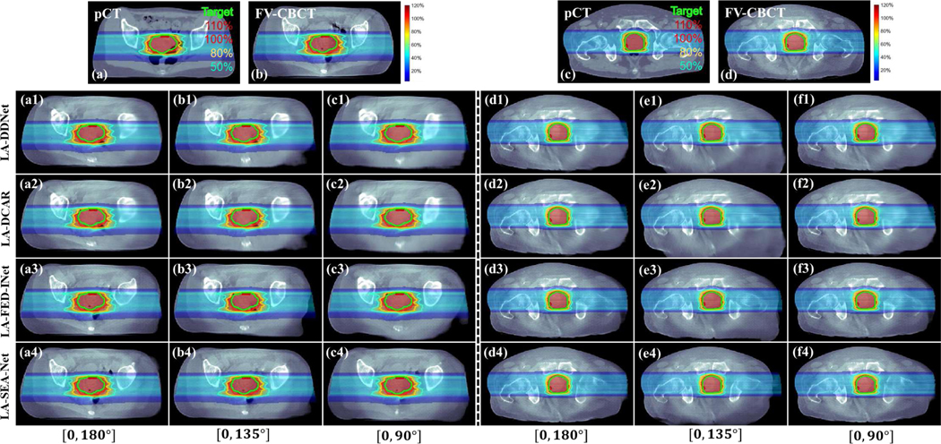
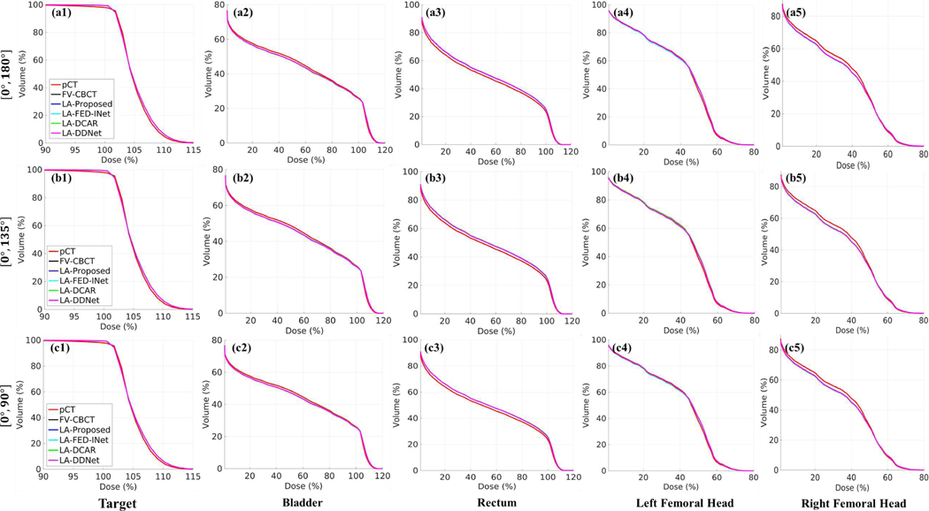
Further, Figs. 9–10 illustrate the dose and DVH plots of different methods with different scanning ranges. Similar to the conclusions in Table IV, LA-CBCT results processed by DL-based methods present a promising potential in the evaluation of dose distribution.
Fig. 9.
Dose plots for different methods and scanning ranges. Results of (a1)-(c4) and (d1)-(f4) are different cases. (a) and (c) Dose plots on the pCT. (b) and (d) Dose plots on the FV-CBCT. (a1)-(a4) and (d1)-(d4) Dose plots with the scanning range [0°, 180°]. (b1)-(b4) and (e1)-(e4) Dose plots with the scanning range [0°, 135°]. (c1)-(c4) and (f1)-(f4) Dose plots with the scanning range [0°, 90°]. (a1)-(f1) Dose plots provided by DDNet method. (a2)-(f2) Dose plots provided by DCAR method. (a3)-(f3) Dose plots provided by FED-INet method. (a4)-(f4) Dose plots provided by SEA-Net method. The dose plot window is [0%, 120%]. 50%, 80%, 100%, and 110% isodose lines and PTV are highlighted.
Fig. 10.
Dose-volume histogram (DVH) plots for different methods with different scanning ranges from one case. (a1)-(a5) DVH plots with the scanning range [0°, 180°]. (b1)-(b5) DVH plots with the scanning range [0°, 135°]. (c1)-(c5) DVH plots with the scanning range [0°, 90°]. (a1)-(c1) DVH plots of target. (a2)-(c2) DVH plots of bladder. (a3)-(c3) DVH plots of rectum. (a4)-(c4) DVH plots of left femoral head. (a5)-(c5) DVH plots of the right femoral head.
According to experimental results, the limited-angle scanning mode is feasibly applied to radiation therapy.
VI. Conclusion And Discussion
Due to the superiority in providing patients’ three-dimensional anatomic structures, there has been a rapid growth of CBCT in RT, which was beneficial to make IGRT a routine technique employed worldwide [44]. However, in real scenarios, CBCT usually takes a longer time to collect projection data, which may lead to motion artifacts and decrease the treatment accuracy. LA-CBCT is an effective tool in lowering scanning time and consequently reducing the motion artifacts. However, the reconstruction images of LA-CBCT will suffer from severe degradation. This work successfully developed an LA-CBCT reconstruction method that can be practically used for real clinical projection data and finally be applied to RT applications.
It is challenging to reconstruct high-quality images from limited-angle projection data. Many advanced methods have been developed, including pre-processing [10], post-processing [12], dual-domain [37], and deep iterative methods [26]. These algorithms improve the image quality in wedge artifact removal and tissue restoration compared to traditional methods. However, most of them are validated on simulated or preclinical data. In this work, we explored various DL methods and developed an image-domain-based method termed SEA-Net for clinical projection data. To the best of our knowledge, this is the first feasibility study of the real clinical-projection-data-based LA-CBCT.
Classical image-domain-based models usually employ deeper neural networks to enhance the image feature extraction [45] or apply GAN and PL to boost the detail restoration [31]. Based on the observation that wedge artifacts in limited-angle CT are directionally distributed, MSWDNet attempted to compensate for the artifacts in the wavelet domain [12]. Further, Zhang et al. proposed DDNet with the combination of dense connections to enlarge the feature representation capacity [24]. Meanwhile, with the specialized loss functions, EGAN [23] and FED-INet [18] were developed to encourage edge recovery. Unlike above typical single-branch network architectures, some works have reported that multi-branch models could significantly improve the utilization rates of image features [20, 25]. Inspired by them, our SEA-Net adopts two-branch architectures that additionally design a structure-enhanced network. By explicitly extracting the texture images, the proposed SEA-Net gains great promotion in detail preservation. Besides, noticing the non-uniform property of artifact distribution in limited-angle problems, spatial attention is utilized to emphasize the relevant regions and ignore the irrelevant ones. All the experiments are performed on clinical projection data and results show that the proposed SEA-Net has superior performance than other competitive algorithms in subtle structure restoration. Particularly, DCAR has demonstrated competitive performance in some cases [23, 33], but it only shows similar results with image-domain methods in this work. Meanwhile, Sam’s Net, which is considered a representative of dual-domain and deep iterative methods [16], is modified to apply to 3D imaging. However, the results indicate that SEA-Net still works better than the modified Sam’s Net. Therefore, deep iterative methods might be unfit for our clinical data. So, it is reasonable for this work to take the image-domain-based model.
Meanwhile, we also conduct experiments to probe the feasibility of the LA-CBCT in clinical RT. Specifically, two applications were investigated, including patient setup and dose calculation. Experiments showed that all the DL methods share similar performances, which indicated that the patient setup and dose calculation were less dependent on images when the LA-CBCT image quality reached a fixed threshold. To sum up, the limited-angle scanning manner can provide promising results within allowable error ranges.
Although the proposed SEA-Net exhibits impressive results in LA-CBCT, there are still some limitations needed to be noticed. First, as observed in Fig. 4, the perceptual loss brings obvious chessboard artifacts that may cause unexpected consequences. Therefore, how to eliminate these artifacts without compromising the edge projection of the proposed method is the next key point. Second, it still has room to improve the patient setup accuracy when the scanning range is small, e.g., [0°, 90°]. Further investigation of LA-CBCT should be performed. Additionally, in this work, each scanning range needs to train a new SEA-Net model, which inevitably increases the training costs. Fortunately, recent works [46, 47] state that diffusion-model-based methods can deal with arbitrary scanning ranges with a pre-trained model. In the future, we will introduce the diffusion model to our clinical data. With more effective techniques, we believe that the LA-CBCT is potential for RT and other real scenes.
Acknowledgments
Dianlin Hu, Yikun Zhang, Wangyao Li, Weijie Zhang and Hao Gao were partially supported by National Institutes of Health grants (R37CA250921 and R01CA261964) and a University of Kansas Cancer Center physicist-scientist recruiting grant; Yang Chen was partially supported by Key Research and Development Programs in Jiangsu Province of China grants BE2021703 and BE2022768, State Key Project of Research and Development Plan grant 2022YFC2401600, National Natural Science Foundation of China grant T2225025
Contributor Information
Dianlin Hu, Department of Radiation Oncology, University of Kansas Medical Center, KS 66160, USA; Jiangsu Provincial Joint International Research Laboratory of Medical Information Processing, the Laboratory of Image Science and Technology, the School of Computer Science and Engineering, and the Key Laboratory of New Generation Artificial Intelligence Technology and Its Interdisciplinary Applications (Southeast University), Ministry of Education, Nanjing 210096, China..
Yikun Zhang, Department of Radiation Oncology, University of Kansas Medical Center, KS 66160, USA; Jiangsu Provincial Joint International Research Laboratory of Medical Information Processing, the Laboratory of Image Science and Technology, the School of Computer Science and Engineering, and the Key Laboratory of New Generation Artificial Intelligence Technology and Its Interdisciplinary Applications (Southeast University), Ministry of Education, Nanjing 210096, China..
Wangyao Li, Department of Radiation Oncology, University of Kansas Medical Center, KS 66160, USA.
Weijie Zhang, Department of Radiation Oncology, University of Kansas Medical Center, KS 66160, USA.
Krishna Reddy, Department of Radiation Oncology, University of Kansas Medical Center, KS 66160, USA.
Qiaoqiao Ding, Institute of Natural Sciences & School of Mathematical Sciences & MOE-LSC & SJTU-GenSci Joint Lab, Shanghai Jiao Tong University, Shanghai, 200240, China..
Xiaoqun Zhang, Institute of Natural Sciences & School of Mathematical Sciences & MOE-LSC & SJTU-GenSci Joint Lab, Shanghai Jiao Tong University, Shanghai, 200240, China..
Yang Chen, Jiangsu Provincial Joint International Research Laboratory of Medical Information Processing, the Laboratory of Image Science and Technology, the School of Computer Science and Engineering, and the Key Laboratory of New Generation Artificial Intelligence Technology and Its Interdisciplinary Applications (Southeast University), Ministry of Education, Nanjing 210096, China..
Hao Gao, Department of Radiation Oncology, University of Kansas Medical Center, KS 66160, USA.
References
- [1].Jaffray DA, Siewerdsen JH, Wong JW et al. , “Flat-panel cone-beam computed tomography for image-guided radiation therapy,” International Journal of Radiation Oncology*Biology*Physics, vol. 53, no. 5, pp. 1337–1349, 2002. [DOI] [PubMed] [Google Scholar]
- [2].Zeng L, Guo J, and Liu B, “Limited-angle cone-beam computed tomography image reconstruction by total variation minimization and piecewise-constant modification,” Journal of Inverse Ill-Posed Problems, vol. 21, no. 6, pp. 735–754, 2013. [Google Scholar]
- [3].Xie S, Huang W, Yang T. et al. , “Compressed Sensing based Image Reconstruction with Projection Recovery for Limited Angle Cone-Beam CT Imaging,” in 42nd Annual International Conference of the IEEE Engineering in Medicine & Biology Society (EMBC), 2020, pp. 1307–1310. [DOI] [PubMed] [Google Scholar]
- [4].Xu M, Hu D, Luo F. et al. , “Limited-Angle X-Ray CT Reconstruction Using Image Gradient ℓ₀-Norm With Dictionary Learning,” IEEE Transactions on Radiation and Plasma Medical Sciences, vol. 5, no. 1, pp. 78–87, 2021. [Google Scholar]
- [5].Huang Y, Würfl T, Breininger K. et al. , “Some Investigations on Robustness of Deep Learning in Limited Angle Tomography,” in Medical Image Computing and Computer Assisted Intervention, 2018, pp. 145–153. [Google Scholar]
- [6].Zhang Y, Hu D, Lyu T. et al. , “PIE-ARNet: Prior Image Enhanced Artifact Removal Network for Limited-Angle DECT,” IEEE Transactions on Instrumentation and Measurement, vol. 72, pp. 1–12, 2023. [DOI] [PMC free article] [PubMed] [Google Scholar]
- [7].Hu D, Zhang Y, Zhu J. et al. , “TRANS-Net: Transformer-Enhanced Residual-Error AlterNative Suppression Network for MRI Reconstruction,” IEEE Transactions on Instrumentation and Measurement, vol. 71, pp. 1–13, 2022. [Google Scholar]
- [8].Wu W, Hu D, An K. et al. , “A High-Quality Photon-Counting CT Technique Based on Weight Adaptive Total-Variation and Image-Spectral Tensor Factorization for Small Animals Imaging,” IEEE Transactions on Instrumentation and Measurement, vol. 70, pp. 1–14, 2021.33776080 [Google Scholar]
- [9].Wu W, Guo X, Chen Y. et al. , “Deep Embedding-Attention-Refinement for Sparse-View CT Reconstruction,” IEEE Transactions on Instrumentation and Measurement, vol. 72, pp. 1–11, 2023.37323850 [Google Scholar]
- [10].Li Z, Zhang W, Wang L. et al. , “A sinogram inpainting method based on generative adversarial network for limited-angle computed tomography,” in 15th International Meeting on Fully Three-Dimensional Image Reconstruction in Radiology and Nuclear Medicine, 2019, pp. 345–349. [Google Scholar]
- [11].Chen H, Zhang Y, Kalra MK et al. , “Low-Dose CT With a Residual Encoder-Decoder Convolutional Neural Network,” IEEE Transactions on Medical Imaging, vol. 36, no. 12, pp. 2524–2535, 2017. [DOI] [PMC free article] [PubMed] [Google Scholar]
- [12].Gu J, and Ye JC, “Multi-scale wavelet domain residual learning for limited-angle CT reconstruction,” arXiv preprint arXiv:.01382, 2017. [Google Scholar]
- [13].Gupta H, Jin KH, Nguyen HQ et al. , “CNN-Based Projected Gradient Descent for Consistent CT Image Reconstruction,” IEEE Transactions on Medical Imaging, vol. 37, no. 6, pp. 1440–1453, 2018. [DOI] [PubMed] [Google Scholar]
- [14].Lin WA, Liao H, Peng C. et al. , “DuDoNet: Dual Domain Network for CT Metal Artifact Reduction,” in IEEE/CVF Conference on Computer Vision and Pattern Recognition (CVPR), 2019, pp. 10504–10513. [Google Scholar]
- [15].Ghani MU, and Karl WC, “Data and Image Prior Integration for Image Reconstruction Using Consensus Equilibrium,” IEEE Transactions on Computational Imaging, vol. 7, pp. 297–308, 2021. [DOI] [PMC free article] [PubMed] [Google Scholar]
- [16].Chen C, Xing Y, Gao H. et al. , “Sam’s Net: A Self-Augmented Multistage Deep-Learning Network for End-to-End Reconstruction of Limited Angle CT,” IEEE Transactions on Medical Imaging, vol. 41, no. 10, pp. 2912–2924, 2022. [DOI] [PubMed] [Google Scholar]
- [17].Chen G, Hong X, Ding Q. et al. , “AirNet: Fused analytical and iterative reconstruction with deep neural network regularization for sparse-data CT,” Medical Physics, vol. 47, no. 7, pp. 2916–2930, 2020. [DOI] [PubMed] [Google Scholar]
- [18].Hu D, Zhang Y, Liu J. et al. , “DIOR: Deep Iterative Optimization-Based Residual-Learning for Limited-Angle CT Reconstruction,” IEEE Transactions on Medical Imaging, vol. 41, no. 7, pp. 1778–1790, 2022. [DOI] [PubMed] [Google Scholar]
- [19].Dong Y, Liu Y, Zhang H. et al. , “FD-GAN: Generative adversarial networks with fusion-discriminator for single image dehazing,” in Proceedings of the AAAI Conference on Artificial Intelligence, 2020, pp. 10729–10736. [Google Scholar]
- [20].Ma C, Rao Y, Lu J. et al. , “Structure-Preserving Image Super-Resolution,” IEEE Transactions on Pattern Analysis and Machine Intelligence, vol. 44, no. 11, pp. 7898–7911, 2022. [DOI] [PubMed] [Google Scholar]
- [21].Woo S, Park J, Lee J-Y et al. , “Cbam: Convolutional block attention module,” in Proceedings of the European conference on computer vision (ECCV), 2018, pp. 3–19. [Google Scholar]
- [22].Zhou H, Zhu Y, Zhang H. et al. , “Multi-scale dilated dense reconstruction network for limited-angle computed tomography,” Physics in Medicine & Biology, vol. 68, no. 7, pp. 075013, 2023/03/27, 2023. [DOI] [PubMed] [Google Scholar]
- [23].Hu D, Zhang Y, Liu J. et al. , “SPECIAL: Single-Shot Projection Error Correction Integrated Adversarial Learning for Limited-Angle CT,” IEEE Transactions on Computational Imaging, vol. 7, pp. 734–746, 2021. [Google Scholar]
- [24].Zhang Z, Liang X, Dong X. et al. , “A Sparse-View CT Reconstruction Method Based on Combination of DenseNet and Deconvolution,” IEEE Transactions on Medical Imaging, vol. 37, no. 6, pp. 1407–1417, 2018. [DOI] [PubMed] [Google Scholar]
- [25].Cai Q, Li J, Li H. et al. , “TDPN: Texture and Detail-Preserving Network for Single Image Super-Resolution,” IEEE Transactions on Image Processing, vol. 31, pp. 2375–2389, 2022. [DOI] [PubMed] [Google Scholar]
- [26].Zhou B, Zhou SK, Duncan JS et al. , “Limited View Tomographic Reconstruction Using a Cascaded Residual Dense Spatial-Channel Attention Network With Projection Data Fidelity Layer,” IEEE Transactions on Medical Imaging, vol. 40, no. 7, pp. 1792–1804, 2021. [DOI] [PMC free article] [PubMed] [Google Scholar]
- [27].Cheng W, Wang Y, Li H. et al. , “Learned Full-Sampling Reconstruction From Incomplete Data,” IEEE Transactions on Computational Imaging, vol. 6, pp. 945–957, 2020. [Google Scholar]
- [28].Wang J, Zeng L, Wang C. et al. , “ADMM-based deep reconstruction for limited-angle CT,” Physics in Medicine & Biology, vol. 64, no. 11, pp. 115011, 2019. [DOI] [PubMed] [Google Scholar]
- [29].Zhang K, Zuo W, Chen Y. et al. , “Beyond a Gaussian Denoiser: Residual Learning of Deep CNN for Image Denoising,” IEEE Transactions on Image Processing, vol. 26, no. 7, pp. 3142–3155, 2017. [DOI] [PubMed] [Google Scholar]
- [30].Yin X, Zhao Q, Liu J. et al. , “Domain Progressive 3D Residual Convolution Network to Improve Low-Dose CT Imaging,” IEEE Transactions on Medical Imaging, vol. 38, no. 12, pp. 2903–2913, 2019. [DOI] [PubMed] [Google Scholar]
- [31].Yang Q, Yan P, Zhang Y. et al. , “Low-Dose CT Image Denoising Using a Generative Adversarial Network With Wasserstein Distance and Perceptual Loss,” IEEE Transactions on Medical Imaging, vol. 37, no. 6, pp. 1348–1357, 2018. [DOI] [PMC free article] [PubMed] [Google Scholar]
- [32].Simonyan K, and Zisserman A. J. a. p. a., “Very deep convolutional networks for large-scale image recognition,” arXiv:1409.1556., 2014. [Google Scholar]
- [33].Huang Y, Preuhs A, Lauritsch G. et al. , “Data consistent artifact reduction for limited angle tomography with deep learning prior,” in International workshop on machine learning for medical image reconstruction, 2019, pp. 101–112. [Google Scholar]
- [34].Gao H, “Fast parallel algorithms for the x-ray transform and its adjoint,” Medical Physics, vol. 39, no. 11, pp. 7110–7120, 2012. [DOI] [PMC free article] [PubMed] [Google Scholar]
- [35].Gao H, “Fused analytical and iterative reconstruction (AIR) via modified proximal forward–backward splitting: a FDK-based iterative image reconstruction example for CBCT,” Physics in Medicine & Biology, vol. 61, no. 19, pp. 7187, 2016. [DOI] [PubMed] [Google Scholar]
- [36].Wu W, Hu D, Niu C. et al. , “DRONE: Dual-Domain Residual-based Optimization NEtwork for Sparse-View CT Reconstruction,” IEEE Transactions on Medical Imaging, vol. 40, no. 11, pp. 3002–3014, 2021. [DOI] [PMC free article] [PubMed] [Google Scholar]
- [37].Zhang Q, Hu Z, Jiang C. et al. , “Artifact removal using a hybrid-domain convolutional neural network for limited-angle computed tomography imaging,” Physics in Medicine & Biology, vol. 65, no. 15, pp. 155010, 2020. [DOI] [PubMed] [Google Scholar]
- [38].Anirudh R, Kim H, Thiagarajan JJ et al. , “Lose the Views: Limited Angle CT Reconstruction via Implicit Sinogram Completion,” in IEEE/CVF Conference on Computer Vision and Pattern Recognition, 2018, pp. 6343–6352. [Google Scholar]
- [39].Xu Y, Bai T, Yan H. et al. , “A practical cone-beam CT scatter correction method with optimized Monte Carlo simulations for image-guided radiation therapy,” Physics in Medicine & Biology, vol. 60, no. 9, pp. 3567, 2015. [DOI] [PMC free article] [PubMed] [Google Scholar]
- [40].Mageras GS, and Mechalakos J, “Planning in the IGRT Context: Closing the Loop,” Seminars in Radiation Oncology, vol. 17, no. 4, pp. 268–277, 2007. [DOI] [PubMed] [Google Scholar]
- [41].Barateau A, De Crevoisier R, Largent A. et al. , “Comparison of CBCT-based dose calculation methods in head and neck cancer radiotherapy: from Hounsfield unit to density calibration curve to deep learning,” Medical Physics, vol. 47, no. 10, pp. 4683–4693, 2020. [DOI] [PubMed] [Google Scholar]
- [42].Usui K, Ichimaru Y, Okumura Y. et al. , “Dose calculation with a cone beam CT image in image-guided radiation therapy,” Radiological Physics and Technology, vol. 6, no. 1, pp. 107–114, 2013. [DOI] [PubMed] [Google Scholar]
- [43].Wieser H-P, Cisternas E, Wahl N. et al. , “Development of the open-source dose calculation and optimization toolkit matRad,” Medical Physics, vol. 44, no. 6, pp. 2556–2568, 2017. [DOI] [PubMed] [Google Scholar]
- [44].Alaei P, and Spezi E, “Imaging dose from cone beam computed tomography in radiation therapy,” Physica Medica, vol. 31, no. 7, pp. 647–658, 2015/11/01/, 2015. [DOI] [PubMed] [Google Scholar]
- [45].Pan J, Zhang H, Wu W. et al. , “Multi-domain integrative Swin transformer network for sparse-view tomographic reconstruction,” Patterns, vol. 3, no. 6, pp. 100498, 2022. [DOI] [PMC free article] [PubMed] [Google Scholar]
- [46].Song Y, Shen L, Xing L. et al. , “Solving inverse problems in medical imaging with score-based generative models,” arXiv preprint arXiv:.08005, 2021. [Google Scholar]
- [47].Lee S, Chung H, Park M. et al. , “Improving 3D Imaging with Pre-Trained Perpendicular 2D Diffusion Models,” arXiv preprint arXiv:.08440, 2023. [Google Scholar]


