Abstract
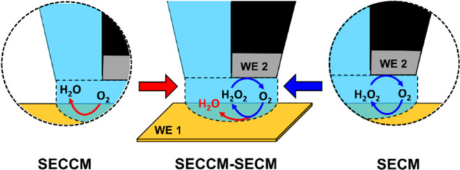
Scanning electrochemical microscopy (SECM) and scanning electrochemical cell microscopy (SECCM) were integrated in a single bifunctional probe for simultaneous mapping of the oxygen reduction current and the oxidation current of the produced H2O2. The dual probe is fabricated from a double-barrel θ capillary, comprising one open barrel filled with the electrolyte and another filled with pyrolytic carbon. Pt is deposited with a gas injection system (GIS) at the end of the carbon barrel. The probe integrates the advantages of both SECM and SECCM by forming an electrochemical droplet cell that embeds the Pt working electrode of the carbon barrel directly into the electrolyte meniscus formed upon sample contact from the electrolyte barrel. The versatility of the dual probe is demonstrated by mapping the oxygen reduction reaction (ORR) current and the H2O2 oxidation current of a Pt microstrip on a gold substrate. This allows simultaneous localized electrochemical measurements, highlighting the potential of the dual probe for broader applications in characterizing the electrocatalytic properties of materials.
Introduction
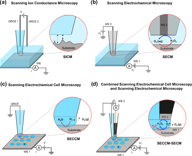
Electrocatalysis plays a crucial role in the energy transition toward the establishment of a sustainable energy infrastructure and reducing our reliance on fossil fuels.1,2 This requires a rational development of suitable catalytic materials for electrochemical energy conversion reactions, coupled with a comprehensive understanding of the electrode/electrolyte interface and the critical parameters that define the catalytic properties of the materials, specifically activity, selectivity, and long-term stability. In this context, scanning electrochemical probe microscopy (SEPM) techniques have been used for local investigation of the electrode/electrolyte interface and have revealed valuable insights into surface and interfacial processes in heterogeneous catalysis.3−12 These techniques include scanning ion conductance microscopy (SICM),13−17 scanning electrochemical microscopy (SECM),18−22 and scanning electrochemical cell microscopy (SECCM).23−26 The working principle and cell configuration of SICM, SECM, and SECCM are schematically illustrated in Figure 1a–c, respectively.
Figure 1.
Schematic illustration of different electrochemical cell configurations in scanning probe techniques: (a) scanning ion conductance microscopy (SICM), (b) scanning electrochemical microscopy (SECM), (c) scanning electrochemical cell microscopy (SECCM), and (d) the proposed integrated SECCM-SECM configuration.
In SICM, a nanopipette is employed to scan a substrate bathed in the electrolyte, where an ionic current flows between an electrode inside the pipet and an external electrode in the bath solution.13 In SECM, an ultramicroelectrode (UME) is immersed in the electrolyte and moved above the surface of the substrate to scan its structural features and chemical reactivity in feedback mode or generation collection mode.18 SECCM stands out among SEPM as a highly robust and versatile technique.23−26 It involves the use of a nanopipette probe to conduct local electrochemical measurements within a confined meniscus cell that defines the sample electrode surface and, with this, the spatial resolution of SECCM by the wetted contact area.
Through the integration of an additional SECM tip electrode to the end of a main SEPM tip, the capabilities of SEPM techniques can be expanded to include simultaneous detection of electrochemical responses from reaction products or intermediates generated at the main SEPM tip or the underlying working electrode surface. This type of integration of a second tip has resulted in hybrid SEPM techniques such as SICM–SECM for the simultaneous mapping of surface topography and electrochemical reactivity of a solid substrate,27−35 and multifunctional SECM–SECM probes for the simultaneous local detection of locally generated species of an electrochemical reaction.36−38 Considering that SECCM typically operates with a nano- to microdroplet-sized cell, the integration of SECCM with SECM enables the simultaneous visualization of both electrocatalytic activity and selectivity across large sample areas without the need to continuously immerse the sample surface into electrolyte solution as common in SECM experiments.
Integrated SECCM–SECM has been so far reported for a quad-probe setup comprising two diagonally opposite open barrels filled with electrolyte and two carbon working electrodes.39 The quad-probe system is controlled by a quad-potentiostat along with an additional potentiostat for measuring the substrate current. The stability of the connecting droplet is provided by the two opposite electrolyte barrels, ensuring that the droplet adequately covers both working carbon electrodes within its confined volume. However, the current configuration involves a complex five-electrode setup, as well as porous carbon electrodes. Hence, the challenge is to refine the SECCM–SECM quad-probe configuration toward a simpler and more robust setup for simultaneous mapping of activity and selectivity during electrocatalytic reactions.
We introduce a comparatively simple and straightforward method for fabricating a novel type of bifunctional SECCM–SECM probes. The dual probe is fabricated from a double-barrel θ capillary, comprising one open barrel filled with the electrolyte and another filled with pyrolytic carbon. Electrical contact in the carbon barrel is established using a copper wire, while a silver wire serves as a quasi-reference counter electrode (QRCE) and is immersed in the electrolyte-filled barrel. The probe integrates the advantages of both SECM and SECCM by forming an electrochemical droplet cell that embeds the Pt working electrode of the carbon barrel directly into the electrolyte meniscus formed upon sample contact from the electrolyte barrel. The multifunctional probe can be positioned on a substrate using SECCM approach to droplet contact, facilitating simultaneous localized measurements of activity and selectivity at electrocatalytically active surfaces and interfaces. The versatility of the technique is demonstrated by simultaneous mapping of the oxygen reduction reaction (ORR) activity and the H2O2 oxidation current generated during the ORR on a platinum microstrip deposited on a gold substrate.
Experimental Section
Fabrication of the Dual-Probe Nanopipette
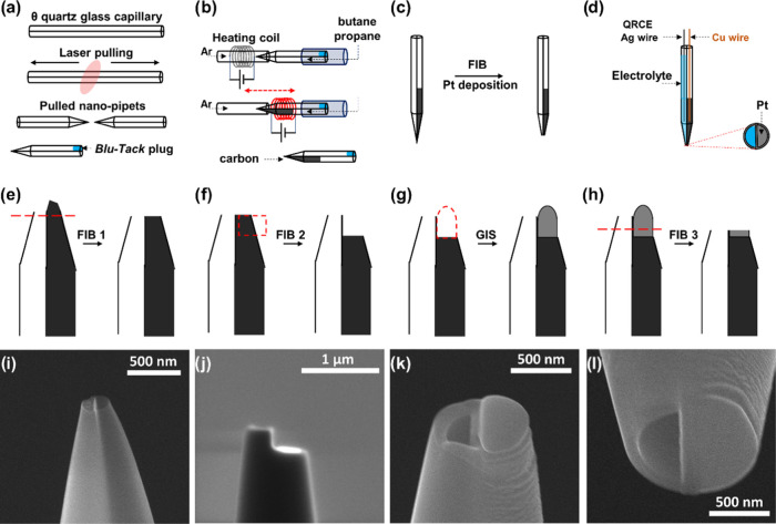
The dual probe is fabricated from quartz glass (OD = 1.2 mm, ID = 0.9 mm) double-barrel θ capillaries (Sutter Instruments) and pulled to a sharp end using a P-2000 laser puller (Sutter Instruments). The pulling parameters were set in a one-line program: Heat = 840, Filament = 4, Velocity = 45, Delay = 130, and Pull = 90. By changing the pulling parameters, a wide range of probe sizes can be obtained. Subsequently, the top end of one barrel is sealed with a plug of “Blu-Tack” (Bostik) as shown in Figure 2a (∼5 min). To deposit pyrolytic carbon inside the pulled pipet, a gas mixture of propane (technical grade) and n-butane (99.5%) is passed through the open barrel, while the pipet tip is positioned in a ceramic capillary under a counter-flow of argon (99.999%). Subsequently, the pipet tip is subjected to heating with a surrounding coil that moves along the pipet (Figure 2b), controlled by a two-stage, in-house developed program regulating the coil movement and heating current.40 In the first stage, pyrolytic carbon is deposited on the inner wall of the pipet, and in the second stage, it extends in the entire heated volume of the pipet (∼3 min). The temperature profile of the two-stage pyrolysis is depicted in Figure S1. After that, the obtained nanopipette undergoes further processing with focused ion beam (FIB) milling (∼5 min) and gas injection system (GIS) (∼2 min) in scanning electron microscopy (SEM) to obtain a controlled deposition of Pt on top of the carbon barrel, and to optimize the surface of the pipet after deposition (Figure 2c). The used SEM setup is an FEI Quanta 3D dual beam (SEM & FIB) equipped with a (Ga+) source. For an effective FIB milling process, a copper wire is inserted from the back end of the capillary to prevent electrostatic charging.
Figure 2.
Schematic illustration of the fabrication steps of the dual-probe tip. After laser-pulling of the double-barrel capillary, one barrel is closed using Blu-Tack (a), and a butane-propane mixture is passed through the open barrel. To deposit carbon pyrolytically, the tip of the pipet is heated in a two-step process under an argon atmosphere (b). After pyrolysis, the probe is assessed with FIB-SEM and a GIS (c). Schematic of the fabricated dual-probe (d): one working electrode of deposited Pt on pyrolytic carbon in the barrel of the probe connected with a Cu wire, the open barrel is filled with electrolyte, and an Ag-wire QRCE is inserted from the back. The currents and applied voltages of each working electrode with respect to ground are controlled separately. The pipet is assessed with FIB-SEM in the first step (e), then milled to prepare a platform for Pt deposition on the carbon side (f). Pt deposition using GIS (g). FIB cutting after GIS (h). Corresponding SEM micrograph (side view) of the dual probe before (i) and after (j) FIB cutting. SEM micrograph of the end of a dual-probe (k) showing deposited Pt (right) and open barrel (left). Micrograph of the tip after Pt deposition and FIB milling (l).
Scanning Electrochemical Cell Microscopy (SECCM)
All electrochemical measurements were conducted using an in-house-built SECCM setup controlled by an FPGA card (USB-7855R, National Instruments—NI) and LabVIEW software (National Instruments). The setup comprises a positioning system and two ELC-03XS voltammetric amplifiers (npi electronic). Precise positioning and movement of the probe close to the substrate is ensured by an x–y–z micromanipulator (OWIS) and a nanocube piezo amplifier (Physik Instrumente—PI) for coarse and fine movement, respectively. The whole setup is placed inside a Faraday cage and mounted on an active vibration-damping TS-140 table (Table Stable).
Results and Discussion
After fabrication of the dual SECCM–SECM probe, the dual probe is used for electrochemical scanning measurements. The micrograph in Figure 2k illustrates a typical dual probe featuring an open channel for the electrolyte on the left side and a smooth Pt surface on the right side for detecting reaction intermediates and/or products.
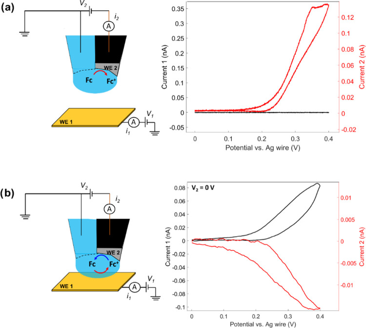
A Ag-wire QRCE is inserted into the electrolyte-filled SECCM barrel from the back, while a Cu wire is inserted into the carbon barrel. The configuration of the dual probe prepared for electrochemical measurements is depicted in Figure 2d. The potential of the substrate (V1) and the Pt-tip (V2) are controlled with respect to the ground, and the current through the substrate (I1) and the Pt-tip (I2) are measured independently in a bipotentiostat configuration as illustrated in Figure 3. Subsequently, cyclic voltammograms (CVs) at the Pt-tip within the dual-probe droplet cell were recorded in 1 mM ferrocenedimethanol (Fc(MeOH)2) in 0.05 M KOH before (in air) and after droplet contact (approached) with a gold substrate electrode in a generator-collector mode configuration. In air (Figure 3a), the potential V2 of the Pt-tip was scanned at a scan rate of 1 V s–1 with respect to ground, while the potential of the QRCE was maintained at ground. The CVs at the Pt-tip (W2) shows a typical Fc(MeOH)2/Fc+(MeOH)2 redox response, and evidently, the current of the Au substrate is zero since the droplet cell was not yet formed. After SECCM approach and formation of the droplet cell (Figure 3b), the potential of the Au substrate (V1) was scanned between 0 and 0.4 V, while the potential of the tip (V2) was kept at 0 V for the reduction of the Fc+(MeOH)2 generated at the Au substrate back to Fc(MeOH)2. A clear Fc(MeOH)2/Fc+(MeOH)2 response was obtained also at the Au substrate, with a simultaneous Fc+(MeOH)2 reduction at the Pt-tip confined within the SECCM droplet, as shown by the black and red CVs in Figure 3b, respectively. The collection efficiency which is the quotient between the current at the sample and the current at the SECM tip (Figure 3b) can be relatively small. Higher values can be obtained with the probe positioned in very close proximity to the substrate as shown in Figure S4. Overall, this confirms the intended functioning of the dual-probe nanopipette and especially that the Pt-tip electrode could be confined within the droplet cell formed adjacently by the SECCM pipet.
Figure 3.
Schematic of the fabricated dual-SECCM–SECM probe in air (a) and when it approached to an Au substrate surface (b), with the corresponding voltammetric responses for each case. The SECCM capillary is filled with 1 mM 1,1′-ferrocendimethanol in 0.05 M KOH. Current 1 represents the substrate current, while current 2 represents the tip current.
After electrochemical testing on a single spot with Fc(MeOH)2/Fc+(MeOH)2 as free diffusing redox mediator, the feasibility of the dual SECCM–SECM tip for continuous electrochemical surface interrogation was assessed using a SECCM hopping mode for the formation of an array of droplet cells. The oxygen reduction reaction (ORR) activity of the Au substrate and its selectivity concerning the formation of H2O or H2O2 are investigated with the dual-probe tip filled with 0.05 M KOH electrolyte. The potential of the Au substrate (V1) was scanned from 1 to −1.5 V to map the ORR activity, while the potential of the Pt tip (V2) was maintained at 0.6 V for the oxidation of any generated H2O2 back to O2. Electrochemical ORR and H2O2 oxidation current maps were obtained through a series of line scans over an area of 100 by 100 μm2, with a hopping distance between the SECCM landing sites of 20 μm. For the flat FIB cut, the tip often exhibits a typical CV response in air. However, the system is turning to current overload immediately when the tip approaches the substrate (Figure S2d, Supporting Information (SI)). The current overload can be attributed to the instability of the formed SECCM droplet. A comparable behavior was noted during the optimization of the Pt deposition with GIS when a small disk of Pt was deposited on the carbon side of the probe, as depicted in the SEM micrographs of Figure S2. The small difference in height between the Pt disk and the empty barrel hinders the formation of a stable droplet that adequately covers the Pt disk. Consequently, this condition leads to an electrical short-circuit between the Pt disk and the Au substrate. In contrast, the flat FIB cut (Figure 2h,k) enables a proper electrochemical response of the Au substrate. Since the response of the flat FIB cut cannot be guaranteed for the whole scanned area, the FIB process needs further optimization prior to the electrochemical mapping.
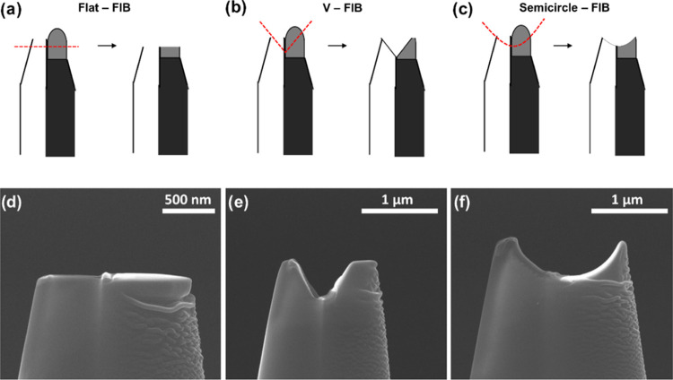
For the optimization of the FIB-cutting process, three cutting configurations of the dual probe, illustrated in Figure 4, were tested including the flat-cut, the V-cut, and the semicircle-cut.
Figure 4.
Schematic illustration of different FIB cutting configurations: flat (a), V-shape (b), and semicircle (c) with their corresponding SEM micrographs (d–f), respectively.
Among these, the semicircle-cut demonstrated the best response, with nearly 100% of the SECCM landing points exhibiting a proper electrochemical response of the Pt-tip and the Au substrate currents, respectively. Scanning with the V-cut probe was successful at approximately 33% of the landing sites, while the flat-cut was successful in less than 10% of the landing sites. Typical voltammetric responses of failed approaches are shown in Figure S2d,e. For the semicircle-cut probe, typical LSVs obtained in 5 × 5 landings (25 spots) arrays can be found in Figures S5 and S6. The efficient performance of the semicircle-cut dual-probe can be attributed to the stability of the droplet in the confined volume. The semicircle-cut offers an optimal geometry integrating the Pt surface within the spherical droplet, and the entire droplet within the probe. This confined volume serves to safeguard the droplet from damage during the approach, retraction, and lateral movement of the tip during the scan, while concurrently ensuring that the deposited Pt surface remains immersed within the electrolyte.
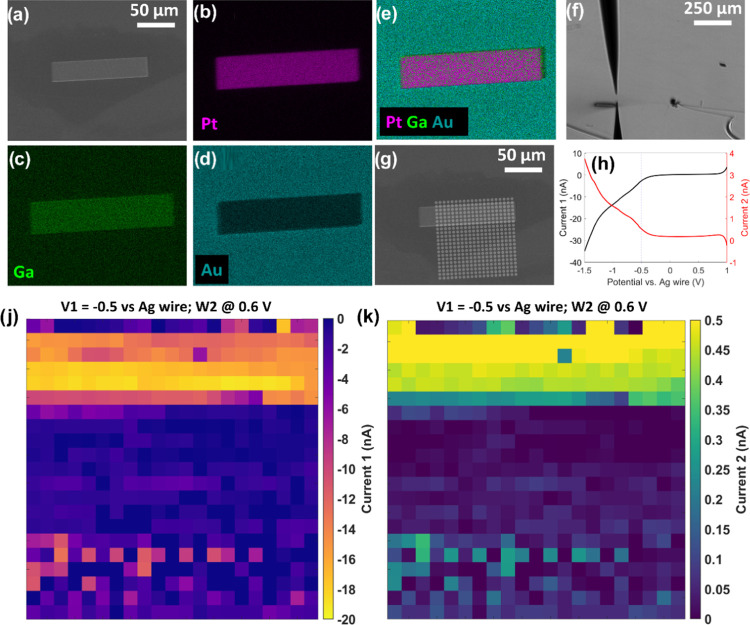
After the optimization of the FIB-cut configuration, electrochemical ORR and H2O2 oxidation current maps are generated from a series of line scans, where the probe is moved laterally in a 100 × 100 μm2 area with a hopping distance of 5 μm. The substrate is a 120 × 30 μm2 Pt microstrip deposited using GIS on the flat Au substrate. An SEM image of the microstrip is presented in Figure 5a, along with the corresponding energy dispersive X-ray (EDX) elemental mapping for Pt, Ga, and Au, in Figure 5b–d, respectively. The dimensions of the microstrip are within the scanning area (Figure 5g) and can serve as an ideal case study for demonstrating simultaneous mapping of both oxygen reduction and H2O2 oxidation currents.
Figure 5.
SEM micrograph of the Au substrate with the deposited Pt microstrip (a), EDX elemental mapping of Pt (b), Ga (c), and Au (d), and the corresponding EDX map sum spectrum of Pt–Ga on Au (e). Digital microscope image of the dual-probe positioned on top of the sample at the top-right side of the Pt strip (f). SEM micrograph where the landing points in the scanned area are marked in white circles (g). Typical LSVs for one landing spot during the SECCM scan (h). The black LSV presents the response of the Au substrate (ORR), and the red LSV shows the response of the Pt-tip (H2O2 detection). 2D oxygen reduction (j) and H2O2 oxidation (k) current maps of the scanned area constructed from a series of line scans at a potential of −0.5 V.
Typical LSVs obtained for one landing spot are shown in Figure 5h, featuring an increasing reduction current on the Au substrate due to increasing ORR (black LSV) and concurrently, an increasing H2O2 oxidation current on the Pt-tip (red LSV). This symmetry in the LSVs indicates that the oxidation rate at the Pt-tip is dependent on the formation of the products at the Au substrate, resembling an SECM generator-collector experiment or a rotating ring disk electrode (RRDE) system. The substrate and the tip currents at an applied potential of −0.5 V are extracted from the LSVs throughout the whole scan and used to generate an oxygen reduction current map (Figure 5j) as well as a H2O2 oxidation current map (Figure 5k). Maps covering the entire LSV potential range are compiled in the form of ORR activity and H2O2 oxidation movies and shown in the Supporting Information (Supporting Movies M1 and M2, respectively).
Both maps illustrate a region characterized by high oxygen reduction and H2O2 oxidation currents (yellow region), while the rest of the scanned area exhibits low current values (blue region). Given that the SECCM hopping distance during the scan is 5 μm, the width of five scan lines directly correlates with the 30 μm width of the Pt microstrip. In this case, it is worth noting that the electronic properties of the Pt microstrip are altered by the presence of Ga from the Ga+ ion source, and the deposited microstrip is a Pt–Ga alloy (∼16% of Ga). This can explain the higher ORR and H2O2 currents compared to the Au surface, which is supposed to have a higher selectivity toward the formation of H2O2 compared to pure Pt. These experiments clearly demonstrate the versatility of the suggested dual SECCM–SECM probe through its capability for simultaneous visualization of ORR activity and H2O2 production of electrocatalytic surfaces offering a simple yet powerful characterization tool for the electrochemical properties of materials. Most importantly, due to the confinement of the electrolyte droplet in the semicircle-cut of the dual SECCM–SECM probe, oxygen can rapidly diffuse into the droplet and mitigate oxygen depletion as seen in generator-collector SECM experiments. In addition, the sample is not exposed to a prolonged immersion in the electrolyte and a continuous polarization to an externally applied potential, which brings the advantage of SECCM to SECM; generator-collector experiments. The application of the suggested dual SECCM–SECM probes can be extended beyond the detection of H2O2 in ORR to include other electrochemical reactions of interest, in which reaction intermediates and/or products are simultaneously generated and detected with the integrated SECCM-SECM dual probe.
Conclusions
In this study, a straightforward approach for fabricating a novel type of dual SECCM–SECM probes is described. These probes consist of one open barrel containing electrolyte and another barrel filled with pyrolytic carbon, with a small deposition of Pt at the carbon barrel’s end. The probe integrates the advantages of both SECM and SECCM by creating a droplet cell that incorporates the Pt working electrode of the carbon-filled barrel directly within the electrolyte meniscus of the electrolyte barrel. Optimal geometry for embedding the Pt working electrode within the meniscus of the droplet was achieved through FIB milling of the tip in a semicircle shape, enabling efficient simultaneous scanning of activity and selectivity of electrocatalytic surfaces. The versatility of the dual-SECCM–SECM probe is demonstrated by simultaneously mapping the ORR activity and H2O2 production of a Pt microstrip deposited on a gold substrate. In a broader context, the application of the dual probe extends beyond the detection of H2O2 in ORR to encompass other electrochemical reactions of interest. The integration of SECM with SECCM in a single dual probe enables the retrieval of more localized information from electrocatalytic surfaces which is essential to our fundamental understanding of heterogeneous electrocatalysis and offers valuable insights for the development of electrocatalytic materials in postscreening studies for future practical applications.
Acknowledgments
The authors acknowledge the financial contribution of the European Research Council (ERC) under the European Union’s Horizon 2020 research and innovation programme (CasCat [833408]) and the Deutsche Forschungsgemeinschaft (DFG, German Research Foundation) in the framework of the CRC247-388390466 and the CRC1625-506711657.
Supporting Information Available
The Supporting Information is available free of charge at https://pubs.acs.org/doi/10.1021/acs.analchem.4c00149.
Temperature profile of the two-stage carbon pyrolysis; SEM micrograph of the end of a dual-probe showing deposited Pt disk and open barrel, with the corresponding voltammetric responses in air and after the approach; and LSVs obtained in a 5 × 5 scan (25 spots) array measured with a semicircle-cut probe (PDF)
ORR activity map for the entire LSV potential range (Movie M1) (MP4)
H2O2 selectivity map for the entire LSV potential range (Movie M2) (MP4)
The authors declare no competing financial interest.
Supplementary Material
References
- De Luna P.; Hahn C.; Higgins D.; Jaffer S. A.; Jaramillo T. F.; Sargent E. H. What would it take for renewably powered electrosynthesis to displace petrochemical processes?. Science 2019, 364 (6438), eaav3506 10.1126/science.aav3506. [DOI] [PubMed] [Google Scholar]
- Wei H.; Cui D.; Ma J.; Chu L.; Zhao X.; Song H.; Liu H.; Liu T.; Wang N.; Guo Z. Energy conversion technologies towards self-powered electrochemical energy storage systems: the state of the art and perspectives. J. Mater. Chem. A 2017, 5 (5), 1873–1894. 10.1039/C6TA09726J. [DOI] [Google Scholar]
- Baker L. A. Perspective and Prospectus on Single-Entity Electrochemistry. J. Am. Chem. Soc. 2018, 140 (46), 15549–15559. 10.1021/jacs.8b09747. [DOI] [PMC free article] [PubMed] [Google Scholar]
- Bentley C. L.; Kang M.; Unwin P. R. Nanoscale Structure Dynamics within Electrocatalytic Materials. J. Am. Chem. Soc. 2017, 139 (46), 16813–16821. 10.1021/jacs.7b09355. [DOI] [PubMed] [Google Scholar]
- Kang M.; Momotenko D.; Page A.; Perry D.; Unwin P. R. Frontiers in Nanoscale Electrochemical Imaging: Faster, Multifunctional, and Ultrasensitive. Langmuir 2016, 32 (32), 7993–8008. 10.1021/acs.langmuir.6b01932. [DOI] [PubMed] [Google Scholar]
- Lai S. C.; Macpherson J. V.; Unwin P. R. In situ scanning electrochemical probe microscopy for energy applications. MRS Bull. 2012, 37 (7), 668–674. 10.1557/mrs.2012.146. [DOI] [Google Scholar]
- Leonard K. C.; Bard A. J. The study of multireactional electrochemical interfaces via a tip generation/substrate collection mode of scanning electrochemical microscopy: the hydrogen evolution reaction for Mn in acidic solution. J. Am. Chem. Soc. 2013, 135 (42), 15890–15896. 10.1021/ja407395m. [DOI] [PubMed] [Google Scholar]
- Liang Y.; Pfisterer J. H. K.; McLaughlin D.; Csoklich C.; Seidl L.; Bandarenka A. S.; Schneider O. Electrochemical Scanning Probe Microscopies in Electrocatalysis. Small Methods 2019, 3 (8), 1800387 10.1002/smtd.201800387. [DOI] [Google Scholar]
- Santos C. S.; Jaato B. N.; Sanjuán I.; Schuhmann W.; Andronescu C. Operando Scanning Electrochemical Probe Microscopy during Electrocatalysis. Chem. Rev. 2023, 123 (8), 4972–5019. 10.1021/acs.chemrev.2c00766. [DOI] [PMC free article] [PubMed] [Google Scholar]
- Shen Y.; Träuble M.; Wittstock G. Detection of hydrogen peroxide produced during electrochemical oxygen reduction using scanning electrochemical microscopy. Anal. Chem. 2008, 80 (3), 750–759. 10.1021/ac0711889. [DOI] [PubMed] [Google Scholar]
- Takahashi Y.; Kumatani A.; Shiku H.; Matsue T. Scanning Probe Microscopy for Nanoscale Electrochemical Imaging. Anal. Chem. 2017, 89 (1), 342–357. 10.1021/acs.analchem.6b04355. [DOI] [PubMed] [Google Scholar]
- Wang Y.; Skaanvik S. A.; Xiong X.; Wang S.; Dong M. Scanning probe microscopy for electrocatalysis. Matter 2021, 4 (11), 3483–3514. 10.1016/j.matt.2021.09.024. [DOI] [Google Scholar]
- Chen C.-C.; Zhou Y.; Baker L. A. Scanning ion conductance microscopy. Annu. Rev. Anal. Chem. 2012, 5, 207–228. 10.1146/annurev-anchem-062011-143203. [DOI] [PubMed] [Google Scholar]
- McKelvey K.; Perry D.; Byers J. C.; Colburn A. W.; Unwin P. R. Bias modulated scanning ion conductance microscopy. Anal. Chem. 2014, 86 (7), 3639–3646. 10.1021/ac5003118. [DOI] [PubMed] [Google Scholar]
- Page A.; Perry D.; Unwin P. R. Multifunctional scanning ion conductance microscopy. Proc. R. Soc., Ser. A 2017, 473 (2200), 20160889 10.1098/rspa.2016.0889. [DOI] [PMC free article] [PubMed] [Google Scholar]
- Zhou L.; Zhou Y.; Baker L. A. Measuring Ions with Scanning Ion Conductance Microscopy. Interface Mag. 2014, 23 (2), 47–52. 10.1149/2.F05142if. [DOI] [Google Scholar]
- Zhu C.; Huang K.; Siepser N. P.; Baker L. A. Scanning Ion Conductance Microscopy. Chem. Rev. 2021, 121 (19), 11726–11768. 10.1021/acs.chemrev.0c00962. [DOI] [PMC free article] [PubMed] [Google Scholar]
- Bard A. J.; Fan F. R. F.; Kwak J.; Lev O. Scanning electrochemical microscopy. Introduction and principles. Anal. Chem. 1989, 61 (2), 132–138. 10.1021/ac00177a011. [DOI] [Google Scholar]
- Kai T.; Zoski C. G.; Bard A. J. Scanning electrochemical microscopy at the nanometer level. Chem. Commun. 2018, 54 (16), 1934–1947. 10.1039/C7CC09777H. [DOI] [PubMed] [Google Scholar]
- Li M. S.; Filice F. P.; Ding Z. Scanning electrochemical microscopy imaging with laser-pulled probes. J. Electroanal. Chem. 2016, 781, 126–135. 10.1016/j.jelechem.2016.06.043. [DOI] [Google Scholar]
- Polcari D.; Dauphin-Ducharme P.; Mauzeroll J. Scanning Electrochemical Microscopy: A Comprehensive Review of Experimental Parameters from 1989 to 2015. Chem. Rev. 2016, 116 (22), 13234–13278. 10.1021/acs.chemrev.6b00067. [DOI] [PubMed] [Google Scholar]
- Sánchez-Sánchez C. M.; Bard A. J. Hydrogen peroxide production in the oxygen reduction reaction at different electrocatalysts as quantified by scanning electrochemical microscopy. Anal. Chem. 2009, 81 (19), 8094–8100. 10.1021/ac901291v. [DOI] [PubMed] [Google Scholar]
- Bentley C. L.; Kang M.; Unwin P. R. Scanning electrochemical cell microscopy: New perspectives on electrode processes in action. Curr. Opin. Electrochem. 2017, 6 (1), 23–30. 10.1016/j.coelec.2017.06.011. [DOI] [Google Scholar]
- Ebejer N.; Güell A. G.; Lai S. C. S.; McKelvey K.; Snowden M. E.; Unwin P. R. Scanning electrochemical cell microscopy: a versatile technique for nanoscale electrochemistry and functional imaging. Annu. Rev. Anal. Chem. 2013, 6, 329–351. 10.1146/annurev-anchem-062012-092650. [DOI] [PubMed] [Google Scholar]
- Ebejer N.; Schnippering M.; Colburn A. W.; Edwards M. A.; Unwin P. R. Localized high resolution electrochemistry and multifunctional imaging: scanning electrochemical cell microscopy. Anal. Chem. 2010, 82 (22), 9141–9145. 10.1021/ac102191u. [DOI] [PubMed] [Google Scholar]
- Wahab O. J.; Kang M.; Unwin P. R. Scanning electrochemical cell microscopy: A natural technique for single entity electrochemistry. Curr. Opin. Electrochem. 2020, 22, 120–128. 10.1016/j.coelec.2020.04.018. [DOI] [Google Scholar]
- Comstock D. J.; Elam J. W.; Pellin M. J.; Hersam M. C. Integrated ultramicroelectrode-nanopipet probe for concurrent scanning electrochemical microscopy and scanning ion conductance microscopy. Anal. Chem. 2010, 82 (4), 1270–1276. 10.1021/ac902224q. [DOI] [PubMed] [Google Scholar]
- Morris C. A.; Chen C.-C.; Baker L. A. Transport of redox probes through single pores measured by scanning electrochemical-scanning ion conductance microscopy (SECM-SICM). Analyst 2012, 137 (13), 2933–2938. 10.1039/c2an16178h. [DOI] [PubMed] [Google Scholar]
- Nadappuram B. P.; McKelvey K.; Al Botros R.; Colburn A. W.; Unwin P. R. Fabrication and characterization of dual function nanoscale pH-scanning ion conductance microscopy (SICM) probes for high resolution pH mapping. Anal. Chem. 2013, 85 (17), 8070–8074. 10.1021/ac401883n. [DOI] [PubMed] [Google Scholar]
- O’Connell M. A.; Wain A. J. Mapping electroactivity at individual catalytic nanostructures using high-resolution scanning electrochemical-scanning ion conductance microcopy. Anal. Chem. 2014, 86 (24), 12100–12107. 10.1021/ac502946q. [DOI] [PubMed] [Google Scholar]
- Page A.; Kang M.; Armitstead A.; Perry D.; Unwin P. R. Quantitative Visualization of Molecular Delivery and Uptake at Living Cells with Self-Referencing Scanning Ion Conductance Microscopy-Scanning Electrochemical Microscopy. Anal. Chem. 2017, 89 (5), 3021–3028. 10.1021/acs.analchem.6b04629. [DOI] [PubMed] [Google Scholar]
- Panday N.; Qian G.; Wang X.; Chang S.; Pandey P.; He J. Simultaneous Ionic Current and Potential Detection of Nanoparticles by a Multifunctional Nanopipette. ACS Nano 2016, 10 (12), 11237–11248. 10.1021/acsnano.6b06307. [DOI] [PubMed] [Google Scholar]
- Takahashi Y.; Shevchuk A. I.; Novak P.; Murakami Y.; Shiku H.; Korchev Y. E.; Matsue T. Simultaneous noncontact topography and electrochemical imaging by SECM/SICM featuring ion current feedback regulation. J. Am. Chem. Soc. 2010, 132 (29), 10118–10126. 10.1021/ja1029478. [DOI] [PubMed] [Google Scholar]
- Takahashi Y.; Shevchuk A. I.; Novak P.; Zhang Y.; Ebejer N.; Macpherson J. V.; Unwin P. R.; Pollard A. J.; Roy D.; Clifford C. A.; Shiku H.; Matsue T.; Klenerman D.; Korchev Y. E. Multifunctional Nanoprobes for Nanoscale Chemical Imaging and Localized Chemical Delivery at Surfaces and Interfaces. Angew. Chem., Int. Ed. 2011, 50 (41), 9638–9642. 10.1002/anie.201102796. [DOI] [PubMed] [Google Scholar]
- Thakar R.; Weber A. E.; Morris C. A.; Baker L. A. Multifunctional carbon nanoelectrodes fabricated by focused ion beam milling. Analyst 2013, 138 (20), 5973–5982. 10.1039/c3an01216f. [DOI] [PubMed] [Google Scholar]
- Bonazza G.; Girault H. H.; Lesch A.; Daniele S. Simultaneous local sensing of two chemical properties with dual soft probe scanning electrochemical microscopy. Electrochim. Acta 2023, 462, 142752 10.1016/j.electacta.2023.142752. [DOI] [Google Scholar]
- McKelvey K.; Nadappuram B. P.; Actis P.; Takahashi Y.; Korchev Y. E.; Matsue T.; Robinson C.; Unwin P. R. Fabrication, characterization, and functionalization of dual carbon electrodes as probes for scanning electrochemical microscopy (SECM). Anal. Chem. 2013, 85 (15), 7519–7526. 10.1021/ac401476z. [DOI] [PMC free article] [PubMed] [Google Scholar]
- Park S.; Kumar S.; Maier C. S.; Kreth J.; Koley D. Simultaneous Chemical Mapping of Live Biofilm Microenvironmental pH and Hydrogen Peroxide in Real Time with a Triple Scanning Electrochemical Microscopy Tip. Anal. Chem. 2023, 95 (15), 6332–6340. 10.1021/acs.analchem.2c05258. [DOI] [PMC free article] [PubMed] [Google Scholar]
- Nadappuram B. P.; McKelvey K.; Byers J. C.; Güell A. G.; Colburn A. W.; Lazenby R. A.; Unwin P. R. Quad-barrel multifunctional electrochemical and ion conductance probe for voltammetric analysis and imaging. Anal. Chem. 2015, 87 (7), 3566–3573. 10.1021/acs.analchem.5b00379. [DOI] [PubMed] [Google Scholar]
- Wilde P.; Quast T.; Aiyappa H. B.; Chen Y.-T.; Botz A.; Tarnev T.; Marquitan M.; Feldhege S.; Lindner A.; Andronescu C.; Schuhmann W. Towards Reproducible Fabrication of Nanometre-Sized Carbon Electrodes: Optimisation of Automated Nanoelectrode Fabrication by Means of Transmission Electron Microscopy. ChemElectroChem 2018, 5 (20), 3083–3088. 10.1002/celc.201800600. [DOI] [Google Scholar]
Associated Data
This section collects any data citations, data availability statements, or supplementary materials included in this article.


