Abstract
In this paper, we present a new type of isolator based on one-way surface magnetoplasmons (SMPs) at microwave frequencies, and it is the first time that an experimental prototype of isolator with wideband and ultra-high isolation is realized using SMP waveguide. The proposed model with gyromagnetic and dielectric layers is systematically analyzed to obtain the dispersion properties of all the possible modes, and a one-way SMP mode is found to have the unidirectional transmission property. In simulation and experiment with metallic waveguide loaded with yttrium–iron–garnet (YIG) ferrite, the scattering parameters and the field distributions agree well with the analysis and verify the one-way transmission property. The isolation is found to be as high as 80 dB and the typical value of insertion loss is 1 dB. Besides, the one-way transmission band can be controlled by changing the magnetic bias. From theoretical analysis and simulation, it is found that with a tiny value of 10 Oe of the magnetic bias, the relative bandwidth can be tuned to be greater than 50%. Compared with conventional isolators, this one-way SMP isolator has the advantages of ultra-high isolation, wide relative frequency band, and requires much smaller bias field, which has promising potential in non-reciprocal applications.
Keywords: Surface magnetoplasmons (SMPs), Gyromagnetism, Yttrium–iron–garnet (YIG) ferrite, Isolator, Nonreciprocity
Subject terms: Electronics, photonics and device physics; Plasma physics
Introduction
Isolators are important components in many communication systems, and are mainly used to suppress reflected standing waves caused by impedance mismatches between highly-detuned components in microwave systems1–4. One type of isolator, which utilizes resonance absorption, operates near gyromagnetic resonance5,6. In such a device, the magnetized ferrite slab resonates around its gyromagnetic frequency, hence the reverse power is absorbed inside the ferrite bulk. Because of the resonant nature, this device is typically narrowband. Another type of isolator is called field displacement isolator, and utilizes the electric field distribution differences between the forward and reverse waves in a waveguide loaded with ferrite slab7–10. A resistive sheet is placed at the location where the forward wave has low electric field while the reverse wave has maximum electric field value, as a result, the forward wave propagates with minimum attenuation and the reverse wave is absorbed. Nonetheless, such isolator has complicated cavity geometry loaded with additional resistive layer. Additionally, isolator can also be realized by combining a circulator with an external resistive load. In contrast to previous implementations, the reverse power in such cases is absorbed in an external load rather than being dissipated inside the device itself. In the work of11, a stratified dielectric and gyroelectric medium structure was developed as isolator in millimeter wave, which realized non-reciprocal transmissions via different attenuation constants for forward and reverse directions.
Recently, topological electromagnetics (EMs) with extreme optical effects has received great attention12–14, which supports unidirectionally propagating modes. The unidirectional EM modes were first proposed in15, as analogs of quantum Hall edge states in photonic crystals (PhCs)16,17. Such modes were experimentally verified using magneto-optical (MO) PhCs with external static magnetic field18. It is found that these unidirectional modes are immune to backscattering18–20. Since then, several schemes were reported to realize one-way propagation, and among them, the one based on surface magnetoplasmons (SMPs) seems to be most attractive as it has robust mechanism and simple geometry21–26. Unidirectional SMPs with one-way propagating modes have attracted much research interest due to the rich physics of nonreciprocal and topological materials27–30. In the microwave domain, by using ferrite materials with remanence 31, it was also reported that unidirectional SMPs can be achieved without an external magnetic bias 32.
This paper proposes a novel scheme of nonreciprocity, which promises unidirectional transmission with exceedingly high isolation based on gyromagnetic SMP waveguide. We first theoretically analyzed the dispersion and transmission properties of one-way SMP, which is supported by rectangular waveguide loaded with dielectric and gyromagnetic media, isolator was then designed and realized based on this SMP mode. The experimentally observed isolation has reached up to 80 dB, surpassing the ideal isolation limited by the state-of-the-art technique. Besides, this SMP structure has much flexibility in designing and controlling its one-way transmission properties, with the characteristics of wide relative bandwidth greater than 50%, tunable working frequency, and ultra-low demand of magnetic bias.
Theoretical analysis
The basic model of SMPs at microwave frequencies is illustrated in Fig. 1, which consists of a gyromagnetic medium layer and a dielectric layer placed between two parallel metal plates. The dielectric layer has the relative permittivity of and thickness of With an external uniform static magnetic field () applied in z direction, the gyromagnetic material with thickness of has the relative permittivity and permeability tensor
| 1 |
where , , and , with being the precession frequency, being the gyrotropic frequency, and is the damping factor related with the resonance linewidth . Here is the gyromagnetic ratio, and is the saturation magnetization. For the transverse-electric (TE) polarization, the bulk modes in the gyromagnetic medium has the dispersion relation , where is the wavenumber, (Voigt permeability), and being the vacuum wavenumber, and there exists a bandgap with which ranges from to . Note that this bandgap vanishes if the medium is not magnetized (i.e., ).
Figure 1.
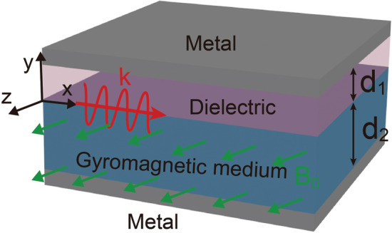
Schematic of the basic model of one-way SMPs at microwave frequencies.
The existence of the SMP mode in the considered system closely relies on the bandgap of the gyromagnetic medium. For the SMP mode propagating along the interface between the gyromagnetic material and dielectric at , the fields in the system are TE-polarized, and the nonzero component of the electric field (E) can be written as
| 2 |
in the dielectric layer and
| 3 |
in the gyromagnetic medium, where is the propagation constant, , and . The nonzero components of the magnetic field ( and ) can be obtained straightforwardly from . The metal layer in this structure is assumed to be a perfect electric conductor (PEC), which is a good approximation for microwave regime. Thus, the tangential component vanishes at the metal boundaries and , yielding and . By applying boundary conditions at the interface , which require continuity of tangential field components and , the dispersion relation of SMPs can be obtained as
| 4 |
It can be found that the SMP mode has an asymptotic frequency of , at which .
As the dielectric cladding is terminated by metal boundary, the propagation constant (k) of the SMP mode is allowed to be smaller than in this system. In this case, , where is a real-valued number. Correspondingly, the dispersion relation of the SMP mode becomes
| 5 |
The SMP mode with can exist even when the thickness of the dielectric layer is close to zero, hence it is rather different from regular modes, which are guided based on the total internal reflection. In the bandgap of the gyromagnetic medium, the dielectric layer in this system may support regular modes with , and these modes are bidirectionally propagating in general. Due to its transverse resonance, each regular mode exists only when the thickness of the dielectric layer is larger than a certain value. The dispersion relation of the regular modes has the same form as Eq. (5). These bidirectional regular modes need to be concerned about, as they are a detriment to the unidirectional frequency window of the waveguide. It is desired that in the bandgap of the gyromagnetic medium, regular modes can be suppressed by reducing the dielectric layer thickness.
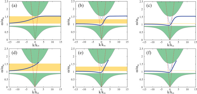
Under a typical material parameters with , , and , the dispersion curves of possible modes in the proposed waveguide are numerically calculated for different values, , and , with fixed , where . As shown in Fig. 2, the solid blue lines represent the SMP mode lying within the bandgap of the gyromagnetic medium, while the dotted lines are the regular modes. The light lines of free space are represented by dashed red line as reference, and the bulk mode zones in the gyromagnetic medium are represented by the green shaded areas. For thin dielectric layer as in Fig. 2a, the dispersion line of SMP monotonically increases and continuously passes through point, and no regular mode exists within the bandgap of the gyromagnetic medium. The unidirectional window is highlighted with yellow shaded area. As the dielectric layer increases, the dispersion line drops down in the light cone of free space. Meanwhile, a regular mode appears in the bandgap of the gyromagnetic medium, as seen in Fig. 2b and c. The lower cutoff frequency of this regular mode decreases when increases, and consequently, the unidirectional window is compressed from top. As comparison, we also plot the SMP dispersion curves in Fig. 2d–f for the corresponding cases of semi-infinite gyromagnetic medium . In such cases, the dispersion relation for SMP mode becomes.
| 6 |
Figure 2.
Normalized dispersion relations of SMPs for various dielectric thickness values (a) , (b) , and (c) , with fixed . Dispersion relations of SMPs for various dielectric thickness values (d) , (e) , and (f) , with semi-infinite gyromagnetic medium . Here , .
It can be seen that as the gyromagnetic medium thickness is big enough, higher value will not change the dispersion property too much, as it is surface wave along the interface and decaying inside the medium.
Numerical simulation
To validate the proposed theory, we perform the simulation using time domain finite integral technique (FIT). The setup of the simulation is shown in Fig. 3, a metallic waveguide is loaded with a slab of gyromagnetic ferrite with thickness , a layer of air with above the ferrite, with dielectric constant . The waveguide is filled with high dielectric constant ceramics at both input and output ends to lower its cutoff frequency. TE-mode guided wave is injected by SMA connectors along z direction. The locations of the connectors are carefully chosen within x–y plane to match the input impedance of the SMP waveguide, and a waveguide ridge is also introduced near the connectors for impedance matching. The gyromagnetic ferrite is set with the parameters of , and , with an external magnetic bias of . As a result, , , and , which is identical to the parameters in the theoretical analysis. Two cases with ferrite length and are simulated.
Figure 3.
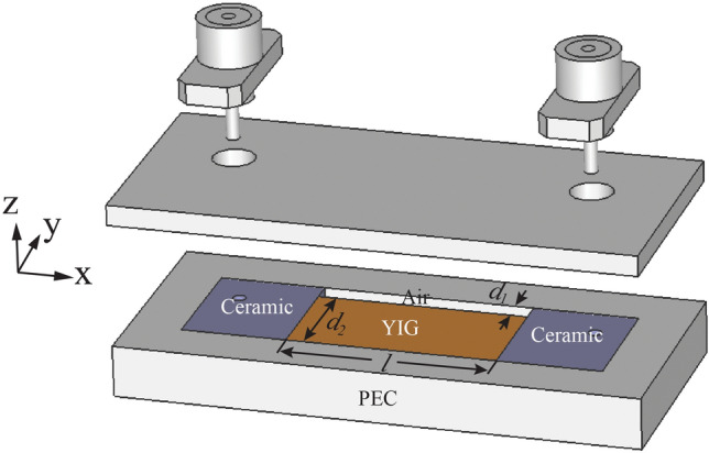
Simulation structure of the proposed one-way SMPs.
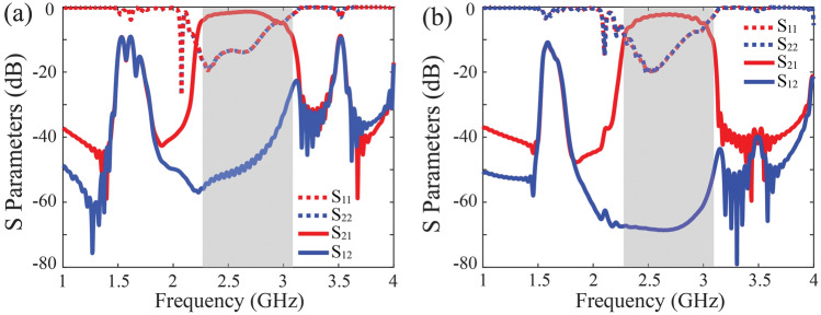
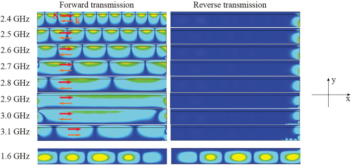
The simulated S parameters of the proposed structure are shown in Fig. 4. It can be found there is a wide band between 2.3 and 3.1 GHz that the forward wave () can be guided smoothly while the reverse wave () is deeply suppressed, which is highlighted in grey shadow, and it agrees well with theory result in Fig. 2a with one-way transmission band from to . The isolation for the 20 mm long ferrite is 40 dB and it reaches to 70 dB for the 40 mm length. This isolation is due to the one-way transmission property of the SMP mode supported in this band. Despite the one-way transmission property, it can be seen there is still a finite amount of reverse transmission for the shorter ferrite, which is due to tunnelling effect of evanescent wave through the system. Longer ferrite with can effectively suppress the tunnelling effect with ultra-high isolation. It is also found there is a reciprocal pass band near the frequency of 1.6 GHz, which shows the existence of regular modes in the gyromagnetic ferrite, as estimated in theory around . The transmission is suppressed by the waveguide below the cutoff frequency 1.6 GHz. To get an insight into the transmission phenomenon, the field distributions in simulation are drawn in Fig. 5, with a ferrite length of 100 mm to make the field distribution clearer. It can be clearly seen inside the unidirectional window, the forward wave can be guided through the SMP structure along the interface between ferrite and air, the effective wavelength can be found to be small at lower frequencies of the one-way SMP band and approach infinite as the dispersion line crosses , then it decreases as increases to positive value region. On the contrary, the reverse wave is prohibited from entering the waveguide and is stuck at the input end to gradually wear off. It is worth mentioning that the blocked reverse transmitted wave is not reflected to the feeding port, which means the signals from both ports are well injected into the SMP system, here the forward wave can be guided to the output while the reverse wave will be converted to thermal dissipation. Besides, from the phase animation in simulation, the Poynting vector (red arrow in Fig. 5) and wavenumber vector (orange arrow in Fig. 5) have opposite directions below 3 GHz with negative value as theory predicted, and they are in the same direction above 3 GHz with positive value of . For comparison, the wave field at 1.6 GHz beyond the bandgap of the gyromagnetic medium is also shown, and evidently, it is a reciprocal regular mode that is mainly guided by the ferrite medium layer.
Figure 4.
Simulated S parameters of the SMP waveguide with different ferrite lengths (a) mm, (b) mm.
Figure 5.
Simulated field distributions at different frequencies for forward and reverse transmissions. The length of the SMP waveguide is mm in the simulation.
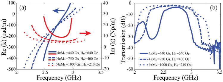
For the one-way SMP mode, the energy is confined near the interface between the ferrite and air, its transmission loss is mainly caused by the loss of ferrite, which is related to the resonance linewidth . Taking the loss effect into account, we calculate the real and imaginary parts of the propagation constant for different values, and the results are plotted in Fig. 6. It can be seen that it has higher loss at two ends of the one-way SMP band, and increasing the value of will generate higher value of transmission loss. Such result is verified by the simulation in Fig. 4, where the forward transmission is lower at the two edges of the one-way SMP band and has higher value in the center. The typical value of transmission loss is 1.5 dB for and 2.5 dB for It should be noted there is still room for improvement of the insertion loss with refined design. Furthermore, we will explore the schemes of the one-way SMP system with minimized insertion loss. In Fig. 7a, the saturation magnetization and the external static magnetic field are carefully tuned to keep the center frequency of the SMP mode unchanged. It is found that with higher value of and smaller , the forward propagation loss of the SMP mode is lower and the one-way SMP mode has wider frequency bandwidth, the resonance linewidth is kept constant Oe. The values of , and set here are all reasonable and commercially available. The transmission properties from FIT simulation in Fig. 7b clearly verify the lower insertion loss and wider bandwidth with larger .
Figure 6.
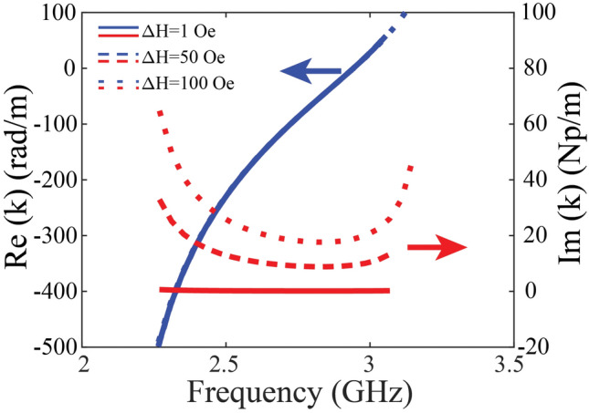
Real and imaginary part of the propagation constants with different values . The effect of the resonance linewidth on the real part of the propagation constant is almost negligible.
Figure 7.
(a) Real and imaginary part of the propagation constants with different values of and , and (b) the corresponding transmission properties of the proposed one-way SMP waveguide in simulation.
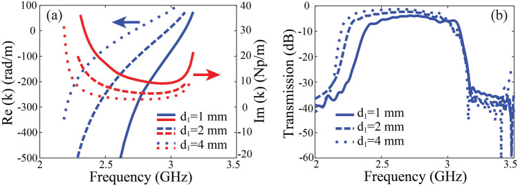
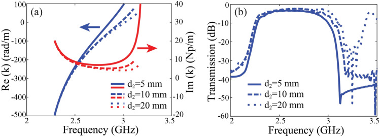
The insertion loss of the unidirectional waveguide is determined by the attenuation constant of the SMP mode, and evidently, it is also related to the geometric parameter . From Fig. 8a, as the air layer thickness increases, the real part of (phase constant) increases, while the imaginary part (attenuation constant) decreases in the unidirectional window. This is mainly because wider air layer causes the SMP field less distributed inside the ferrite medium, so the SMP wave experiences less ferrite loss. The transmission coefficients in simulation are plotted in Fig. 8b and agrees with the calculation in Fig. 8a. We further analyze the influence of the ferrite thickness () on the transmission property of the unidirectional waveguide. The calculated phase and attenuation constants of the SMP mode for different values are plotted in Fig. 9. Interestingly, the attenuation constant of the SMP mode can also be reduced with larger at higher frequencies. The field of the SMP mode in the gyromagnetic medium is an evanescent field, whose distribution is characterized by the penetration depth . It is found that mm at the frequency 3 GHz. Therefore, in the case of mm, the evanescent field does not undergo sufficient attenuation as it reaches the metallic bottom, resulting in a strong reflected field. The superposition of downward and upward evanescent fields enhances the field amplitudes within the gyromagnetic medium. In contrast, when mm, the field of the SMP mode almost monotonously decays in the gyromagnetic medium, and it becomes very weak at the metallic bottom. Clearly, a smaller thickness of the ferrimagnetic medium concentrates the field energy, thereby enhancing energy density and consequently increasing the energy dissipation in the gyromagnetic medium.
Figure 8.
(a) Real and imaginary part of the propagation constants with different values of , and (b) the corresponding transmission properties of the proposed one-way SMP waveguide in simulation.
Figure 9.
(a) Real and imaginary part of the propagation constants with different values of , and (b) the corresponding transmission properties of the proposed one-way SMP waveguide in simulation.
Provided with alternative options of ferrite material, the one-way SMP structure has much flexibility in designing an isolator and can achieve superior performance. A representative example is depicted as in Fig. 10, a one-way SMP mode with dispersion line presented in dotted red line and its corresponding transmission coefficients in forward and reverse directions shown in blue lines, with saturation magnetization Gs and static bias magnetic field Oe. It is seen the SMP mode can be obtained by applying an extremely small magnetic bias, so that it is feasible to utilize pre-oriented ferrites to fabricate self-biased isolator which operates without permanent magnets to drastically decrease the size of the components. The relative bandwidth is higher 50% with typical insertion loss of 1 dB and isolation of greater than 50 dB. These preliminary results demonstrate the possibility of realizing high isolation and wide bandwidth isolator with remanent magnetization in the absence of external magnetic field.
Figure 10.
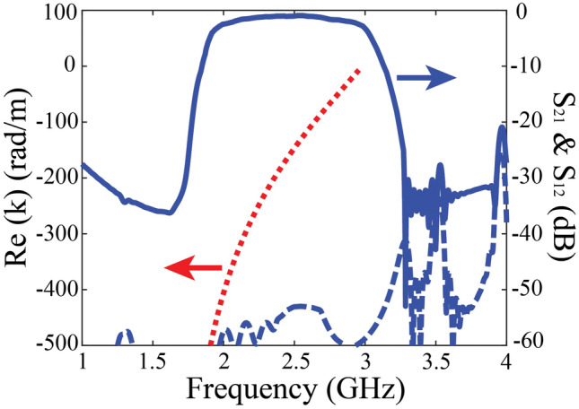
Calculated propagation constant and simulated transmission coefficients with Gs and Oe.
Experimental measurement
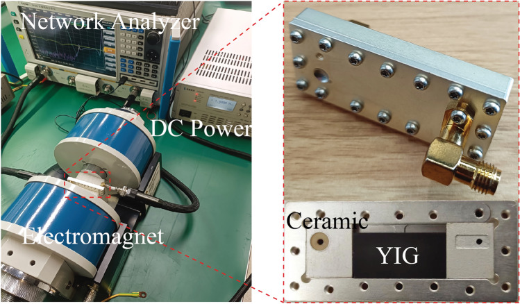
To verify the theoretical analysis and numerical simulation above, we carried out the experiment as shown in Fig. 11, a SMP waveguide is placed vertically between two magnetic poles of an electromagnet (YK230404-122) with uniform static magnetic field, whose strength can be adjusted between 100 and 10,000 Oe by tuning the applied voltage supply. A slab of yttrium–iron–garnet (YIG) ferrite of 10 mm thickness is placed in a metallic waveguide with an air gap of 2 mm apart from the sidewall. The YIG ferrite is designed and claimed to have the same material parameters as those in simulation, with saturation magnetization Gs and resonance linewidth Oe. Two ceramics are placed on each end of the waveguide connected with relative permittivity of 90 to reduce the waveguide cutoff frequency, so that microwave signal can enter the waveguide in the SMP band. Microwave connectors are placed perpendicular to the waveguide to feed TE wave into the SMP system.
Figure 11.
Photos of the experimental setup of the proposed one-way SMP waveguide.
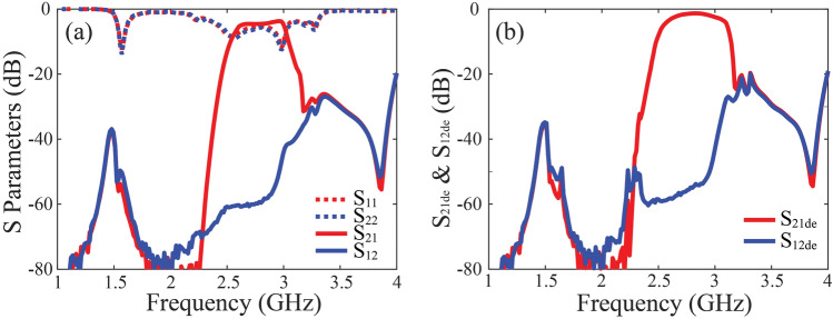
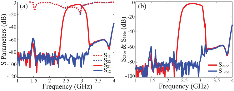
The S parameters of the SMP waveguide are measured using Vector Network Analyzer (Ceyear 3672E 10 MHz–67 GHz), the obtained results are plotted in Fig. 12 for the ferrite of 20 mm length, with the external magnetic bias tuned to be approximately Oe. For plate shape ferrite, the demagnetization factor is approximately , the internal bias magnet of ferrite is , here is the magnetization of the ferrite, which is closed to the saturation magnetization . It can be seen from Fig. 12a there is a wide band of one-way propagation ranging from 2.4 to 3 GHz, with reverse isolation of 40 dB, which is basically agrees with previous simulation. It can be seen the one-way SMP bandwidth is slight narrower than that in simulation, the reason is quite because the practical ferrite parameters are not perfectly identical to the values in simulation, where may be a little smaller than expectation leading to narrower bandwidth, as the above analysis. In addition, the return loss is deteriorated compared with simulation. This is probably because some unexpected fabrication and assembly error is accidentally introduced in experiment, this imperfection in turn impacts the transmission coefficient. We re-calculate the de-embedding coefficients and to remove the imperfect matching influence in Fig. 12b, the typical transmission loss is about 1 dB. Despite the difference, the measurement results still reveal the evident one-way propagation effect and its outstanding isolation performance. Figure 13 shows the results of the 40 mm long YIG with the same parameters. It can be seen the isolation can be as high as 80 dB and the typical value of transmission loss is about 1.5 dB. We should emphasize that the prototype in our experiment is not assembled and tuned well enough to get ideal matching performance, and ferrite material parameters seems deviates from our expectation. Even though, we still verify the excellent performance of ultra-high isolation and relative low transmission loss, and we believe through careful designing the material and geometric parameters of the SMP system, the insertion loss can be further improved.
Figure 12.
(a) Experimental results of the proposed one-way SMPs for 20 mm long YIG ferrite, and (b) the transmission properties with de-embedded unmatching effect.
Figure 13.
(a) Experimental results of the proposed one-way SMPs for 40 mm long YIG ferrite, and (b) the transmission properties with de-embedded unmatching effect.
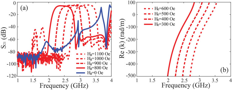
The propagation constant can be obtained from the transmission phase difference between the two SMP structures with 40 mm and 20 mm length, that is , as shown in Fig. 14. The experimental extracted dispersion line is consistent with the theoretical predictions, and further illustrates the one-way transmission induced by the SMP mode. As we adjust the static magnet bias by tuning the electromagnet current supply, the one-way transmission passband shifts to higher band as the magnet bias increases, as shown in Fig. 15a, such one-way SMP mode disappears when no magnet bias is imposed as plotted in blue line. The calculated dispersion lines with different static magnetic bias in Fig. 15b confirm validity of our theory. This character can be utilized in tunable isolator.
Figure 14.
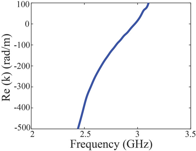
Extracted dispersion curve from experiment.
Figure 15.
(a) Experimental transmission coefficients under different external magnetic bias, and (b) calculated propagation constants.
Conclusion
In this paper, we proposed and theoretical analyzed a new kind isolator based on one-way SMP, and it is the first time that a fully functional prototype of isolator with ultra-high isolation is realized using SMP mode waveguide. By designing the ferrite and dielectric layers with proper material parameters and geometric dimensions, we obtained SMP with one-way transmission. The S parameters and the field distributions from simulation agree well with the analysis and verify the one-way transmission property. Experiments were then carried out in metallic waveguide loaded with YIG ferrite. The isolation is found to be as high as 80 dB with low static magnetic bias, and the typical value of transmission loss can be 1 dB when removing the unideal matching effect. The one-way transmission band can be tuned as the magnetic bias changes. To demonstrate the extraordinary performance of the one-way SMPs as isolator, we provided an example with the relative bandwidth greater than 50 %, and an extreme low demand of magnetic bias of only 10 Oe, which is possible to be realized based on remanence without bulky magnetic bias. Compared with conventional isolator, this one-way SMP mode isolator has not only high-performance but also flexible properties with tunable working frequency, and this new isolator concept has great potential in a variety of non-reciprocal applications.
Author contributions
Tao Jiang wrote the main manuscript text and performed most of the experiment. Dan Liang, Huajie Liang, Lin Zou and Shiqing Li provided provided valuable advices on experiment setup and fabrication. Linfang Shen provided essential theoretical insight and revised the manuscript. Tianchi Zhou provided theory explanations and revision suggestion in the revised manuscript. All authors reviewed the manuscript.
Data availability
The datasets used and/or analysed during the current study available from the corresponding author on reasonable request.
Competing interests
The authors declare no competing interests.
Footnotes
Publisher's note
Springer Nature remains neutral with regard to jurisdictional claims in published maps and institutional affiliations.
Contributor Information
Tao Jiang, Email: jiangtao@csj.uestc.edu.cn.
Tianchi Zhou, Email: zhou_tian_chi@163.com.
References
- 1.van Heijningen, M., van der Bent, G., van der Houwen, E. H., Chowdhary, A., & van Vliet, F. E. L-band AlGaN/GaN power amplifier with protection against load mismatch. In Proceedings of European Microwave Conference 408–411 (Nuremberg, Germany, 2013)
- 2.Yu, S., Yu, H., Yu, J., Yao, Y., Chen, X., & Liu, X. Application of Faraday rotator in transceiver isolation system. In Proceedings of 12th UK-Europe-China Workshop on Millimeter Waves and Terahertz Technologies (UCMMT), 1–3 (London, 2019)
- 3.Adam, J. D., Davis, L. E., Dionne, G. F., Schloemann, E. F. & Stitzer, S. N. Ferrite devices and materials. IEEE Trans. Microw. Theory Techn.50(3), 721–737 (2002). 10.1109/22.989957 [DOI] [Google Scholar]
- 4.Pozar, D. M. Microwave Engineering (Wiley, 2009). [Google Scholar]
- 5.Helszajn, J. & Mckay, M. Circular polarisation in a double-ridge waveguide. IEE Proc. Microwav. Antennas Propag.152(1), 25–30 (2005). 10.1049/ip-map:20041160 [DOI] [Google Scholar]
- 6.Schlomann, E. On the theory of the ferrite resonance isolator. IEEE Trans. Microw. Theory Techn.MTT-8(2), 199–206 (1960). 10.1109/TMTT.1960.1124723 [DOI] [Google Scholar]
- 7.Fesharaki, F., Akyel, C. & Wu, K. Broadband substrate integrated waveguide edge-guided mode isolator. Electron. Lett.49(4), 269–271 (2013). 10.1049/el.2012.2700 [DOI] [Google Scholar]
- 8.Barnes, C. E. Broad-band isolators and variable attenuators for millimeter wavelengths. IEEE Trans. Mic. Theory Tech.9, 519–523 (1961). 10.1109/TMTT.1961.1125383 [DOI] [Google Scholar]
- 9.Matthaei, G. L., Jones, E. M. T. & Cohn, S. B. A nonreciprocal, TEM-mode structure for wide-band gyrator and isolator applications. IRE Trans. Microw. Theory Techn.7(4), 453–460 (1959). 10.1109/TMTT.1959.1125416 [DOI] [Google Scholar]
- 10.Fay, C. E. & Comstock, R. L. Operation of the field displacement isolator in rectangular waveguide. IEEE Trans. Microw. Theory Techn.8(6), 605–611 (1960). 10.1109/TMTT.1960.1124804 [DOI] [Google Scholar]
- 11.Jawad, G. N., Duff, C. I. & Sloan, R. A millimeter-wave gyroelectric waveguide isolator. IEEE Trans. Microw. Theory Techn.65(4), 1249–1256 (2017). 10.1109/TMTT.2016.2640298 [DOI] [Google Scholar]
- 12.Lu, L., Joannopoulos, J. D. & Soljacic, M. Topological photonics. Nature Photon.8(11), 821–829 (2014). 10.1038/nphoton.2014.248 [DOI] [Google Scholar]
- 13.Jin, D. et al. Topological magnetoplasmon. Nat. Commun.7, 13486 (2016). 10.1038/ncomms13486 [DOI] [PMC free article] [PubMed] [Google Scholar]
- 14.Tsakmakidis, K. et al. Breaking Lorentz reciprocity to overcome the time-bandwidth limit in physics and engineering. Science356, 1260 (2017). 10.1126/science.aam6662 [DOI] [PubMed] [Google Scholar]
- 15.Haldane, F. D. M. & Raghu, S. Possible realization of directional optical waveguides in photonic crystals with broken time-reversal symmetry. Phys. Rev. Lett.100, 013904 (2008). 10.1103/PhysRevLett.100.013904 [DOI] [PubMed] [Google Scholar]
- 16.Prange, R. E. & Girvin, S. M. The Quantum Hall Effect (Springer, 1987). [Google Scholar]
- 17.Joannopoulos, J. D., Meade, R. D. & Winn, J. N. Photonic Crystals: Molding the Flow of Light 2nd edn. (Princeton University, 2008). [Google Scholar]
- 18.Wang, Z., Chong, Y. D., Joannopoulos, J. D. & Soljacic, M. Observation of unidirectional backscattering-immune topological electromagnetic states. Nature461, 772 (2009). 10.1038/nature08293 [DOI] [PubMed] [Google Scholar]
- 19.Wang, Z., Chong, Y. D., Joannopoulos, J. D. & Soljacic, M. Reflection-free-one-way edge modes in a gyromagnetic photonic crystal. Phys. Rev. Lett.100, 013905 (2008). 10.1103/PhysRevLett.100.013905 [DOI] [PubMed] [Google Scholar]
- 20.Ao, X., Lin, Z. & Chan, C. T. One-way edge mode in a magneto-optical honeycomb photonic crystal. Phys. Rev. B80, 033105 (2009). 10.1103/PhysRevB.80.033105 [DOI] [Google Scholar]
- 21.Brion, J. J., Wallis, R. F., Hartstein, A. & Burstein, E. Theory of surface magnetoplasmons in semiconductors. Phys. Rev. Lett.28, 1455 (1972). 10.1103/PhysRevLett.28.1455 [DOI] [Google Scholar]
- 22.Yu, Z., Veronis, G., Wang, Z. & Fan, S. One-way electromagnetic waveguide formed at the interface between a plasmonic metal under a static magnetic field and a photonic crystal. Phys. Rev. Lett.100, 23902 (2008). 10.1103/PhysRevLett.100.023902 [DOI] [PubMed] [Google Scholar]
- 23.Khanikaev, A. B. et al. One-way electromagnetic Tamm states in magnetophotonic structures. Appl. Phys. Lett.95(1), 011101 (2009). 10.1063/1.3167356 [DOI] [Google Scholar]
- 24.Fang, K., Yu, Z. & Fan, S. Realizing effective magnetic field for photons by controlling the phase of dynamic modulation. Nat. Photonics6(11), 782–787 (2012). 10.1038/nphoton.2012.236 [DOI] [Google Scholar]
- 25.Khanikaev, A. B. et al. Photonic topological insulators. Nat. Mater.12(3), 233–239 (2013). 10.1038/nmat3520 [DOI] [PubMed] [Google Scholar]
- 26.Rechtsman, M. et al. Photonic Floquet topological insulators. Nature496(7444), 196–200 (2013). 10.1038/nature12066 [DOI] [PubMed] [Google Scholar]
- 27.Hu, B., Wang, Q. J. & Zhang, Y. Broadly tunable one-way terahertz plasmonic waveguide based on nonreciprocal surface magneto plasmons. Opt. Lett.37, 1895 (2012). 10.1364/OL.37.001895 [DOI] [PubMed] [Google Scholar]
- 28.Shen, L. F., Wang, Z. Y., Deng, X. H., Wu, J.-J. & Yang, T.-J. Complete trapping of electromagnetic radiation using surface magnetoplasmons. Opt. Lett.40, 1853 (2015). 10.1364/OL.40.001853 [DOI] [PubMed] [Google Scholar]
- 29.Buddhiraju, S. et al. Absence of unidirectionally propagating surface plasmon-polaritons at nonreciprocal metal-dielectric interfaces. Nat. Commun.11, 674 (2020). 10.1038/s41467-020-14504-9 [DOI] [PMC free article] [PubMed] [Google Scholar]
- 30.Gangaraj, S. A. H. & Monticone, F. Do truly unidirectional surface plasmon-polaritons exist. Optica6, 1158 (2019). 10.1364/OPTICA.6.001158 [DOI] [Google Scholar]
- 31.Pozar, D. M. Microwave Engineering (Wiley, 1998). [Google Scholar]
- 32.You, Y. et al. Unidirectional-propagating surface magnetoplasmon based on remanence and its application for subwavelength isolators. Opt. Mater. Express9, 2415 (2019). 10.1364/OME.9.002415 [DOI] [Google Scholar]
Associated Data
This section collects any data citations, data availability statements, or supplementary materials included in this article.
Data Availability Statement
The datasets used and/or analysed during the current study available from the corresponding author on reasonable request.


