Abstract
Effective radiation therapy aims to maximize the radiation dose delivered to the tumor while minimizing damage to the surrounding healthy tissues, which can be a challenging task when the tissue-tumor space is small. To eliminate the damage to healthy tissue, it is now possible to inject biocompatible hydrogels between cancerous targets and surrounding tissues to create a spacer pocket. Conventional methods have limitations in poor target visualization and device tracking. In this paper, we leverage our MR-tracking technique to develop a novel injection needle for hydrogel spacer deployment. Herein, we present the working principle and fabrication method, followed by benchtop validation in an agar phantom, and MRI-guided validation in tissue-mimic prostate phantom and sexually mature female swine. Animal trials indicated that the spacer pockets in the rectovaginal septum can be accurately visualized on T2-weighted MRI. The experimental results showed that the vaginal-rectal spacing was successfully increased by 12 ± 2 mm anterior-posterior.
Index Terms—: Injection Needle, MRI-Conditional, Active Tracking, Radiation Therapy
I. Introduction
MEDICAL needles are widely used in the clinical environment for a variety of procedures, such as local intramuscular sedation, intravenous chemotherapy delivery, edema reduction, and subcutaneous biomarker insertion, etc. [1]. In brachytherapy-based cancer treatment, injection needles are being used to place hydrogels deep into the body [2, 3]. These hydrogels serve as spacers that distance sensitive, healthy tissues, such as rectum tissues during prostate-cancer treatment, from the tumorous regions that require radiation energy delivery. Prior work indicated that uniform spacing of 10–15 mm can be provided (anterior-posterior) via the hydrogel pocket, reducing the radiation dose to healthy rectal tissue by as much as 80% [4].
Effective radiation reduction to the surrounding healthy tissues is dependent on the accurate placement of the injection needle and the pocket’s boundary. The ideal hydrogel placement procedure is required to have the following key features: 1) accurate visualization of the treated tumor for closed-loop navigation, 2) continuous monitoring of the injection needle for safe insertion, and 3) real-time intraoperative imaging of the hydrogel topology (volume and shape). Conventional hydrogel injection procedures are monitored under Ultrasound (US) or X-ray guidance, which can provide 1–2 of the key features, but not all of them. For example, US is able to track the device in real-time, but lacks the capability to provide high-resolution images of the cancerous regions. X-ray is accurate in needle configuration monitoring, but it is difficult to visualize the soft tissues and also creates additional radiation exposure to the patients and clinicians.
Magnetic Resonance Imaging (MRI) is able to generate high-resolution inter-tissue images without exposure of radiation. Prior work indicated that hydrogel pocket placement could be accurately monitored with MRI feedback [2–4]. However, two limitations have resulted in MRI-guided needle insertion procedures remaining under-used: 1) MRI requirements limit the material selection to prevent imaging artifacts, and 2) the necessity for high-resolution sequences for accurate detection of metallic needles, extending procedure duration and precluding real-time monitoring capabilities [5]. For example, several groups have developed MR-guided devices [6], such as Gosselin et al. [7] and Liu et al. [8]. However, the materials used in these devices result in large imaging artifacts (50 mm diameter in [7]), which would prevent accurate visualization of the hydrogel pocket in our procedure. Hetts et al. have designed micro-coils for flexible endovascular catheter tracking [9], but the device cannot be used for the proposed application as it has insufficient stiffness for the penetration of human tissue [10].
We recently developed a method to integrate novel task-space MR-tracking (MRT) coils onto metallic devices, allowing enhanced navigation speed and accuracy that cannot be achieved with US and X-ray [11]. The MRT coils are RLC circuits that can be tuned and matched to the MRI Larmor frequency, enabling RF signal localization within the MRI coordinate frame with an accuracy of 0.9 mm and feedback rate of 15 Hz. This tracking technique was used to construct MRI-conditional stylets for brachytherapy seed placement [12–14] and elongated metallic catheters for cardiac-electrophysiology ablation therapy [15]. It successfully eliminates the need for developing sophisticated imaging sequences to monitor the needle shape as it is now possible to obtain the full needle shape by embedding several coils and performing basic curve fitting. The potential for expanding the use of MRI guidance to other needle-based interventions shows great promise [16, 17].
In this paper, we hypothesize that the accuracy and efficiency of hydrogel placement can be significantly improved if real-time task-space monitoring of the needle position and pocket topology can be provided with MRI guidance, thereby mitigating the risk of damage to healthy tissue involved with radiation therapy. By integrating our MRT technique onto a custom-designed MRI-conditional titanium needle, we have created a 1) novel injection needle mechanical design optimized through simulation that enables tissue spacing with 2) continuous injection needle localization at a rate of 15 Hz, 3) accurate visualization of the treated tumor, and 4) intraprocedural imaging feedback of the hydrogel topology. The following paper is divided into four sections. Section II describes the design and fabrication of the device, and the MRT integration onto the injection needle. Section III elaborates on the experimental setups and procedures. Section IV provides the experimental results and a discussion of the results. The paper concludes in Section V.
II. Methods
The proposed design was ideated using Axiomatic Design Theory, where we focused heavily on Axiom 1, which states that a designer must attempt to maintain the independence of functional requirements [18]. In this work, the functional requirements consist of (1) task-space MR-tracking, (2) in-situ delivery of the bio-compatible hydrogel, and (3) fit within the current clinical workflow. This differs from our prior work [13], where the functional requirements consisted of (1) task-space MR-tracking, (2) a deflectable tip for stylet positioning, and (3) creating a novel workflow [13]. The difference in functional requirements (2) and (3), while maintaining functional requirement (1) indicates that the functional requirements are decoupled, suggesting a novel design was created using a robust design methodology compatible with varying clinical requirements.
A. Injection Needle Design and Fabrication
Inspired by the principles of concentric- [19–21] and eccentric- [22] tube robots, the proposed injection needle was fabricated from two 30 cm long titanium tubes (ID: 1.20 mm, OD: 1.60 mm, SKU: TiGr2-TB-040 and ID: 0.61 mm, OD: 0.81 mm, SKU: TiGr2-TB-020). Fabrication of the injection needle assembly began with subtractive manufacturing on the outer tube. Two 12.70 mm long grooves were cut axially along the outer tube using a four-flute, 45°, 1/8-inch carbide end mill (SKU 415–1502, Shars Tool, IL, USA), providing a placement location for the MRT coils (Fig. 1A). The inner tube was then inserted into the outer tube and a flat region was produced for MRT coil placement by filling the gap between the inner and outer tubes at the machined grooves with epoxy and sanding the epoxy flat after curing (MarineWeld 50172, JB Weld). Following the curing of the epoxy, a 30° bevel tip was machined onto both nested tubes, and the MRT coils were adhered to the epoxy flatbed (Fig. 1B-C).
Fig. 1.
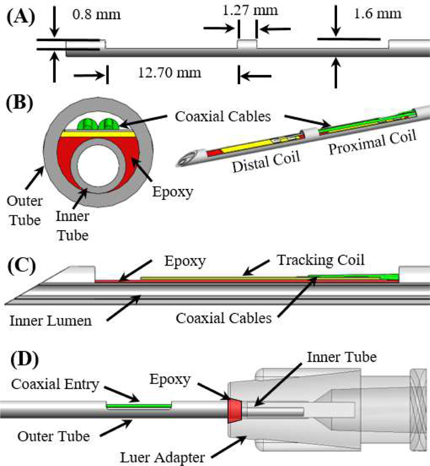
(A) A side view of the outer tube after the machining operations. (B) Front cross-section and isometric view of the MR-tracked needle assembly at the distal end. (C) Side cross-section view of the distal end of the injection needle assembly (proximal coil not visualized). (D) Side view of the proximal end of the needle assembly.
Note that two micro-coaxial (46-AWG) cables were allowed entry into the cavity between the inner and outer tube by machining an opening into the outer tube that was 5 mm long and 0.80 mm deep (Fig. 1D). To prevent leakage between the inner and outer tube, the tubes were attached to a Luer lock (P/N: 11114, Qosina, USA) at the proximal end of the needle using epoxy, with the inner tube extending further into the Luer adapter (Fig. 1D). The entire needle, excluding the distal tip, was coated by a thin (0.05mm wall) heat-shrink tube, which prevented contact between biological fluids and the circuitry.
B. Injection Needle Connection Interface
The proposed system has two connection interfaces: 1) MRT coils to the MRI scanner and 2) injection needle to the hydrogel syringe. The quick connection between the MRT coils and the MRI for tracking signal transmission was provided through a custom-designed electrical adapter, which incorporated a quick-disconnect 5-pin Redel (Lemo, Switzerland) connector. To maintain a compact, ergonomic design, the electrical adapter was made using an SLA printer (Form 3, FormLabs, Massachusetts, USA) that oriented the Redel connector to be parallel with the syringe, as shown in Fig. 2. A hollow channel was created within the electrical adapter to enable easy access to the MRT coils. The connection between the injection needle and syringe was achieved via a Luer connector.
Fig. 2.
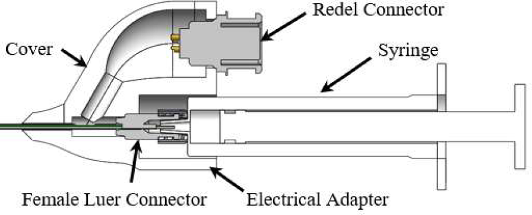
The proposed electrical adapter with the injection needle assembly.
C. MR-Tracking, Balun, and Hardware Integration
Real-time tracking of the injection needle within the MRI scanner was implemented by locating two MRT coils (length, width, and thickness: 8 mm, 1.10 mm, and 0.20 mm), made of a 3-layer flexible-printed-circuit (FPC) with embedded capacitors [23] on the distal end of the needle assembly, as shown in Fig. 3A. The MRT coils were channeled via a tuning, matching, and active decoupling circuit (Fig. 3B). Tuning and matching was performed using a vector network analyzer (NanoVNA-F, SYSJOINT Information Technology Co., LTD, Zhejiang, China). Series capacitors were used to block DC leakage currents from propagating on the device (International Electrotechnical Commission 60601–1), while parallel capacitors and a variable series inductor (P/N: 164-04A06L, Coilcraft, Illinois, USA) were used to tune the circuit to the 1.5T MRI Larmor frequency (63.8 MHz). An S11 reflection coefficient of 53.2 and 41.8 dB were obtained for the proximal and distal MRT coils, respectively (Fig. 3C).
Fig. 3.
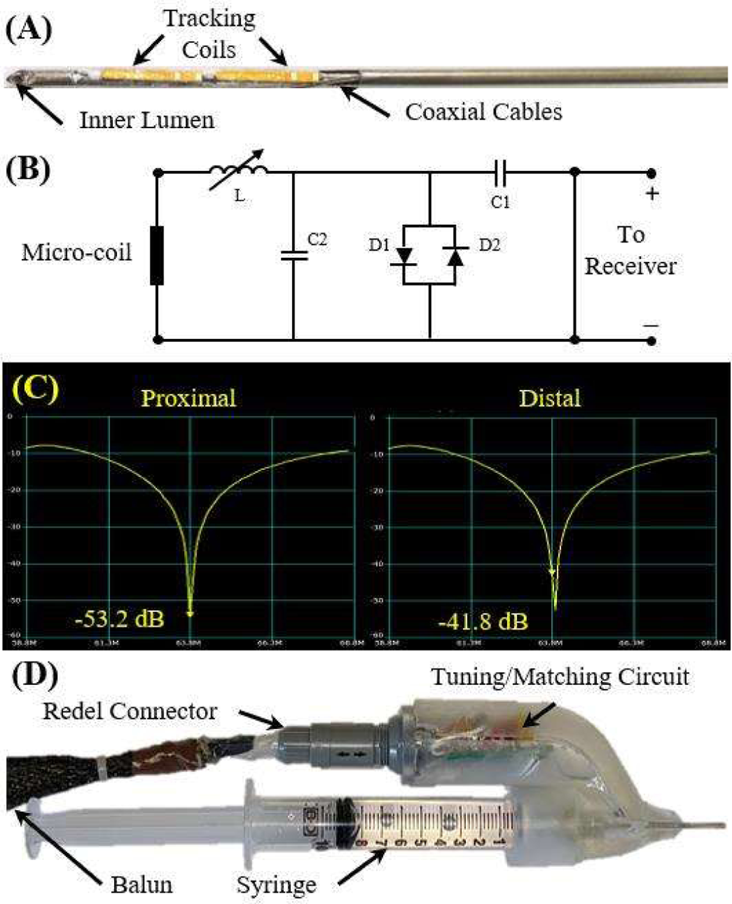
(A) The MRT coils attached to the distal end of the needle. (B) The tuning and matching circuit schematic. (C) The results of the tuning and matching of the circuit for each coil, indicating strong signal transmission. (D) The final prototype of injection needle assembly.
The circuit was connected to the Redel connector in the electrical adapter. Prior to the connection to the receiver, the signals from the MRI receiver propagated on half-wavelength coaxial cables that were overlaid with 30-cm periodic resonant RF traps (Baluns) [15] to attenuate common-mode propagation, reducing cable-heating risk and increasing signal fidelity. The final prototype can be seen in Fig. 3D.
III. Experimental Validations
A. Injection Needle Mechanical Performance
Finite element analysis (FEA) was performed to analyze the effects of the MRT grooves on the needle’s mechanical performance. This was evaluated by analyzing needle-tip trajectory deviation caused by various groove lengths, including 10 mm (no grooves), 5 mm, 12.7 mm (actual design dimension), and 20 mm. The needle insertion procedure is modeled as a separation process of two tissue bodies connected with a thin cohesive layer as presented in [24]. The tissue medium in the simulation was modeled as gelatin, which shares similar mechanical properties of human tissue [25]. The tissue parameters are presented in Table I.
TABLE I.
SIMULATION PARAMETERS
| Parameters | Units | Values |
|---|---|---|
| Needle Length | mm | 300 |
| Tissue Thickness | mm | 60 |
| Young’s Modulus of Tissue | Pa | 7000 |
| Young’s Modulus of Needle | GPa | 120 |
| Poisson Ratio of Tissue | - | 0.475 |
| Poisson Ratio of Needle | - | 0.3 |
Due to the symmetric design of the injection needle, the finite element analysis was created in 2D to improve computational efficiency (Fig. 4). Herein, the y-direction defines the direction of insertion, and the x-direction quantifies the trajectory deviation during insertion. A static solver was used in the FEA study [24]. For the boundary conditions the tissue’s bottom boundary was vertically fixed and its vertical boundaries were horizontally fixed. The insertion distance of the proximal edge of the needle was −70 mm in the y-direction, which is similar to our clinical studies.
Fig. 4.
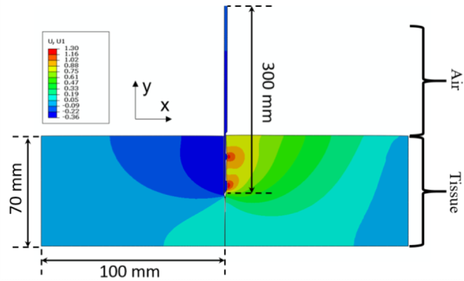
An example of the simulation of the 30 cm long needle entering tissue vertically downwards from the top (with 12.7 mm long grooves) when the insertion depth is at 35 mm of the 70 mm insertion depth. The contours depicted are of strain, indicating that the fibers interacting with the right side of the needle (the side with the grooves) are under tension while the fibers on the left side of the needle body are under compression. The needle successfully eliminates the cohesive element and separates the two tissue bodies.
The simulation was then validated using a linear rail to consistently drive the prototyped needles into an agar phantom at a speed of 1 mm/s using a NEMA 23 stepper motor as shown in Fig. 5. The agar phantom was made using a 5% by volume mixture. The needle tip trajectory was recorded using an electromagnetic (EM) tracker (Aurora, NDI Medical, Ontario, Canada), with the tracking coils placed in the location of the distal MRT coil groove (Fig. 1C). Four different prototypes were made corresponding to the various groove lengths, including 0 mm (no grooves), 5 mm, 12.7 mm (actual design dimension), and 20 mm. Each prototype was inserted into the phantom 10 times while the needle tip trajectory was recorded. Care was taken to ensure that the trajectory of each insertion trial did not traverse through a trajectory cut by a previous needle insertion trial. The recorded position data points were converted to the coordinate system matching the simulation in Fig. 4 using rigid transformation methods [26].
Fig. 5.

Experimental setup for empirical validation of the simulation results.
B. MRI-Guided Phantom Experiment
Experiments were conducted in a Siemens 1.5T Espree MRI scanner using a dedicated MR-tracking sequence that reconstructed the needle-tip location and orientation at a rate of ~15 Hz. The real-time MRT coil positional feedback was sent to a workstation with a 3D Slicer MR-tracking module [27]. The MR-tracking module overlaid needle position and orientation on MR navigational roadmaps and displayed the navigational aid on an in-room monitor.
Phantom experiments were performed with a custom prostate gel phantom (gel conductivity = 0.6 S/m, gel relative dielectric constant = 77). The navigational roadmap was acquired using a T1-weighted Turbo-Spin-Echo (TSE) image dataset array (TR\TE\Ɵ = 500ms\3ms\900, ETL=6, 0.6×0.6×3.0 mm3, 64 slice, 2 min acquisition), which combined the scanner abdominal and spine surface arrays along with the MRT coils. MR-tracking (TR\TE\Ɵ = 2.2ms\1.1ms\50, 0.9×0.9×0.9 mm3 resolution, Hadamard encoding, 5 phase-dithering-directions/projection) was used for needle tracking during the procedure. Once the needle was in position, water was injected into the phantom using a medical syringe and dynamic changes in the injected volume were recorded for 20 seconds using 2D Gradient Recalled Echo (GRE) images (TR\TE\Ɵ=10ms\3ms\500, 2.0×2.0×4.5 mm3, 5 slice/sec).
C. MRI Swine Experiments
A swine experiment was conducted with institutional IACUC approval in a sexually mature (>6mth) female Gottingen mini-pig with a vaginal obturator placed in the vaginal-canal, mimicking the brachytherapy procedure used for gynecologic cancer treatment. The needle was inserted from the open tip of the obturator while observing the navigational workstation. The navigational roadmap was acquired with a T2-weighted TSE dataset (TR\TE\Ɵ = 2000ms\101ms\180, 0.8 × 0.8 × 3.0 mm3). MR-tracking was used during needle navigation to steer the needle. Gd-DTPA-doped water (0.1 mL/L Gadavist, Bayer Healthcare, USA) was injected into the rectovaginal septum to create the hydrogel-filled pocket with images acquired prior to and following pocket creation.
IV. Results and Discussion
A. FEA Simulation
The simulation results (Fig. 6A) show that the injection needle successfully separates the two tissue bodies, regardless of groove length. Overall, tip divergence is approximately proportional to the needle insertion depth. This is primarily due to the bevel tip of the injection needle, which tends to re-direct the needle when it is inserted into the tissue [28], resulting in a tip divergence of the needle’s tip at the end of its trajectory of 0.62 mm, 0.61 mm, 0.58 mm, and 0.55 mm for the groove length of 0 mm, 5 mm, 12.7 mm, and 20 mm, respectively. However, the maximum tip divergence is less than 1 mm for the insertion depth of 70 mm (< 0.8% of insertion depth), which can be neglected due to the scanner’s typical imaging resolution of 1 mm × 1 mm per pixel.
Fig. 6.
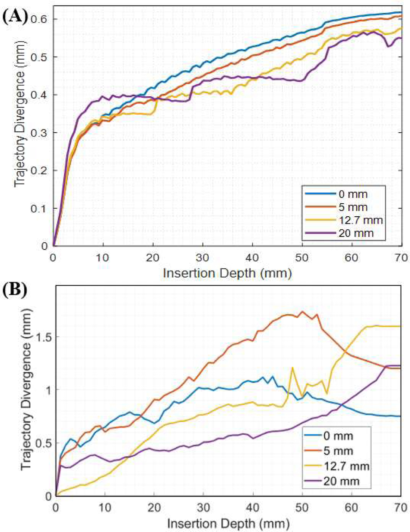
(A) The simulated needle tip deviation from the linear insertion path is plotted with respect to the insertion depth. (B) The tip deviation of the needle tip from the linear insertion path in the experimental setup is plotted with respect to the insertion depth.
The experimental results of the needle insertion trials are presented in Fig. 6B. Plotted is the average tip divergence for the ten trials with respect to the insertion depth for the four different prototypes. Similar to the simulation, tip divergence is approximately proportional to insertion depth, where the tip divergence of the needle’s tip at the end of its trajectory is 0.75 mm, 1.22 mm, 1.60 mm, and 1.20 mm for the groove length of 0 mm, 5 mm, 12.7 mm, and 20 mm, respectively. This results in an error from the simulation results of 0.13 mm, 0.61 mm, 1.02 mm, and 0.65 mm. Note that the tracking accuracy of the Aurora system used was 0.70 mm and the registration error was 0.93 mm, which likely contributes to the error seen. Nonetheless, the linear divergence is small compared to the insertion length (< 2.3%). The minimal divergence observed in both the simulation and the experimental setup indicate that the linear assumption for the insertion trajectory of the device is valid despite the cutouts produced on the distal end of the device for MR-tracking. Thus, we apply this assumption to the device in the swine study discussed in Section IV-C.
B. MRI Phantom Experiment
MR-tracking precision was determined by comparing the ground-truth location of the MRT coil positions to the 3D-Slicer MR Tracking module in the prostate phantom (CIRS, VA, USA). Ground-truth positions were measured using high-resolution 3D MR images acquired by an inversion-recovery gradient echo (MP-RAGE) sequence with a spatial resolution of 0.3×0.3×0.3 mm3. MRT SNR supported 15 Hz navigation with tracking precision of 0.9 × 0.9 × 0.9 mm3 and robust visualization of the tip location and orientation.
To validate dynamic pocket topology visibility, 30 mL of Gd-DTPA-doped water was injected between the prostate and rectum (Fig. 7). The dynamic changes in the volume of the injected fluid were clearly captured, providing real-time feedback on the fluid topology. During the injection procedure, the syringe was swapped out 5 times for injection of additional fluid; however, the needle tip only moved 2 mm, indicating intra-procedural syringe replacement is easy and safe.
Fig. 7.
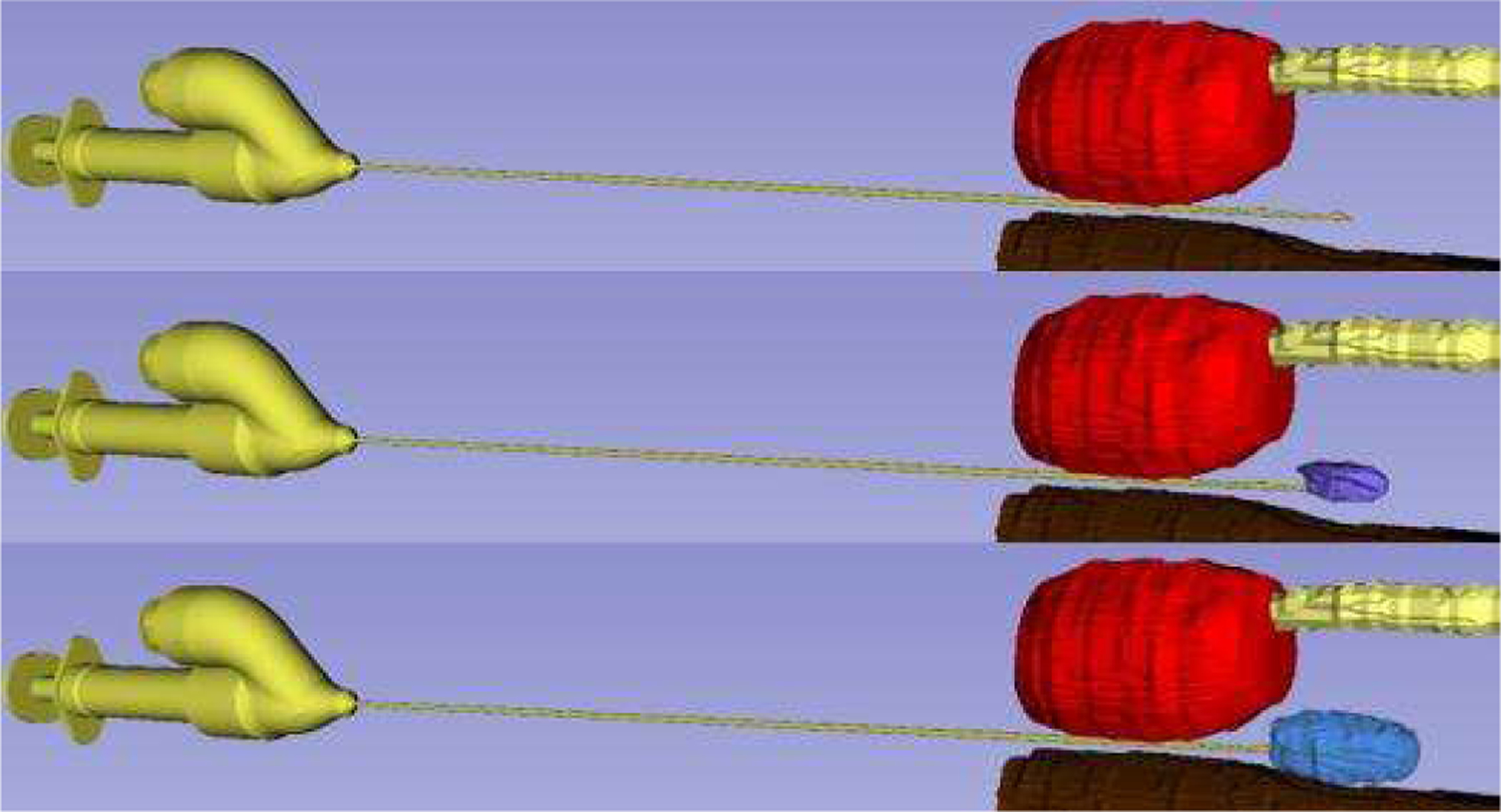
Phantom Experiment. The dynamic visualization of the pocket topology can be viewed between the prostate (red), urethra (yellow), and rectum (brown) with the final (blue) injected volume.
C. MRI Swine Experiment
In this section, the proposed injection needle was evaluated in a live swine. MR-tracked navigation was successfully used to place the injection needle between the vagina and rectum of the swine (Fig. 8). The needle was repositioned 2 times within 20 seconds to achieve the desired targeting performance, but the trajectories were linear, indicating our model was accurate (Section IV-A) in predicting negligible tip divergence. Note that the existing procedures rely on passive image-based tracking, which has a significantly longer procedure time due to slow image feedback during clinician deployment. The animal study performed with the proposed injection needle encourages prompt clinical implementation due to its fast tracking and ease of use, resulting in significantly shorter procedure time.
Fig. 8.

Visualization of a pocket (orange arrows) created between the vagina (green) and the rectum (cyan) in a female mini-pig viewed with T2-w images.
After the injection needle placement, T2-w imaging was performed to monitor the vaginal wall, rectum, and the pocket. The dynamic visualization of injected Gd-DTPA-doped water pocket topology is shown in Fig. 8. A total of 15 mL of the fluid was injected, resulting in an additional spacing of 12 ± 2 mm between the vagina and rectum.
V. Conclusions
This paper presents the design and fabrication, simulation modeling and validation, phantom trial, and animal trial of an MR-tracked injection needle for hydrogel pocket placement. The simulation and benchtop validation results indicated that the bevel tip and MRT coil grooves machined onto the needle had a minimal effect on trajectory deviation, with a limited sub-mm deviation in the direction perpendicular to insertion for a tissue insertion depth of 70 mm. This is supported by the benchtop experiment, where deviations in the tip of the device from a straight line trajectory remained below 2 mm, which also includes the EM tracking coil error of 0.70 mm and registration error of 0.93 mm, as well as manufacturing tolerances of the prototype, such as linearity of the tube. The actively-tracked injection needle was successful at displacing the vagina from the rectum in the swine model by 12±2 mm in the anterior-posterior direction within 20 seconds.
Our future work will first require the validation of the device’s safety. The proposed device requires an open lumen at the distal end for the injection of the hydrogel, resulting in the difficulty of sealing the electronics from the patient. Thus, we will explore hermetic sealing between the patient and the electronics. Following safety validation, we will test the device’s efficacy for hydrogel pocket placement in patient trials. Metrics of comparison will include (i) mean pocket placement time, (ii) pocket placement accuracy, (iii) total damage to healthy tissues, and (iv) tumor size reduction. These metrics will be compared to current procedural results using X-Ray, US, and passively (e.g. image-based) tracked MRI guidance.
Acknowledgments
This research is supported by R01-HL094610, R01-HL126092, and R21-CA167800.
Contributor Information
Anthony L. Gunderman, Biomedical Engineering Department, Georgia Institute of Technology/Emory University, Atlanta, GA, 30318 USA
Ehud J. Schmidt, Department of Medicine, Johns Hopkins University, Baltimore, MD., 21205
Qingyu Xiao, Biomedical Engineering Department, Georgia Institute of Technology/Emory University, Atlanta, GA, 30318 USA.
Junichi Tokuda, Department of Radiology, Harvard Medical School, Boston, MA., 02115.
Ravi T. Seethamraju, Siemens Healthineers Boston, Boston, MA, 02115
Luca Neri, Department of Medicine, Johns Hopkins University, Baltimore, MD., 21205.
Henry R. Halperin, Department of Medicine, Johns Hopkins University, Baltimore, MD., 21205
Carmen Kut, Department of Radiation Oncology, Johns Hopkins University, Baltimore, MD., 21205.
Akila N. Viswanathan, Department of Radiation Oncology, Johns Hopkins University, Baltimore, MD., 21205
Marc Morcos, Department of Radiation Oncology, Johns Hopkins University, Baltimore, MD., 21205.
Yue Chen, Biomedical Engineering Department, Georgia Institute of Technology/Emory University, Atlanta, GA, 30318 USA.
References
- [1].Nelson DB, Bosco JJ, Curtis WD, Faigel DO, Kelsey PB, Leung JW, Mills MR, Smith P, Tarnasky PR, VanDam J, Wassef WY, and Asge, “Technology status evaluation report - Injection needles,” (in English), Gastrointestinal Endoscopy, vol. 50, no. 6, pp. 928–931, Dec 1999. [Online]. Available: <Go to ISI>://WOS:000083941700055. [DOI] [PubMed] [Google Scholar]
- [2].Damato A, Kassic M, and Viswanathan A, “Rectum and bladder spacing in cervical cancer brachytherapy using a novel injectable hydrogel compound,” (in English), Brachytherapy, Article vol. 16, no. 5, pp. 949–955, SEP-OCT 2017. 2017, doi: 10.1016/j.brachy.2017.04.236. [DOI] [PubMed] [Google Scholar]
- [3].Hatiboglu G, Pinkawa M, Vallee J, Hadaschik B, and Hohenfellner M, “Application technique: placement of a prostate-rectum spacer in men undergoing prostate radiation therapy,” (in English), Bju International, Article vol. 110, no. 11B, pp. E647–E652, DEC 2012. 2012, doi: 10.1111/j.1464-410X.2012.11373.x. [DOI] [PubMed] [Google Scholar]
- [4].Marnitz S, Budach V, Weisser F, Burova E, Vercellino F, and Kohler C, “Rectum separation in patients with cervical cancer for treatment planning in primary chemo-radiation,” (in English), Strahlentherapie Und Onkologie, Meeting Abstract vol. 188, pp. 57–58, JUN 2012. 2012. [DOI] [PMC free article] [PubMed] [Google Scholar]
- [5].Sengupta S, Yan X, Hoyt TL, Drake G, Gunderman A, and Chen Y, “Minimal artifact actively shimmed metallic needles in MRI,” Magn Reson Med, vol. 87, no. 1, pp. 541–550, Jan 2022, doi: 10.1002/mrm.28977. [DOI] [PMC free article] [PubMed] [Google Scholar]
- [6].Hu X, Chen A, Luo Y, Zhang C, and Zhang E, “Steerable catheters for minimally invasive surgery: a review and future directions,” Comput Assist Surg (Abingdon), vol. 23, no. 1, pp. 21–41, Dec 2018, doi: 10.1080/24699322.2018.1526972. [DOI] [PubMed] [Google Scholar]
- [7].Gosselin FP, Lalande V, and Martel S, “Characterization of the deflections of a catheter steered using a magnetic resonance imaging system,” Med Phys, vol. 38, no. 9, pp. 4994–5002, Sep 2011, doi: 10.1118/1.3622599. [DOI] [PubMed] [Google Scholar]
- [8].Liu T and Cavusoglu MC, “Three Dimensional Modeling of an MRI Actuated Steerable Catheter System,” IEEE Int Conf Robot Autom, vol. 2014, pp. 4393–4398, 2014, doi: 10.1109/ICRA.2014.6907499. [DOI] [PMC free article] [PubMed] [Google Scholar]
- [9].Hetts SW, Saeed M, Martin AJ, Evans L, Bernhardt AF, Malba V, Settecase F, Do L, Yee EJ, Losey A, Sincic R, Lillaney P, Roy S, Arenson RL, and Wilson MW, “Endovascular catheter for magnetic navigation under MR imaging guidance: evaluation of safety in vivo at 1.5T,” AJNR Am J Neuroradiol, vol. 34, no. 11, pp. 2083–91, Nov-Dec 2013, doi: 10.3174/ajnr.A3530. [DOI] [PMC free article] [PubMed] [Google Scholar]
- [10].Okamura A, Simone C, and O’Leary M, “Force modeling for needle insertion into soft tissue,” (in English), Ieee Transactions on Biomedical Engineering, Article vol. 51, no. 10, pp. 1707–1716, OCT 2004. 2004, doi: 10.1109/TBME.2004.831542. [DOI] [PubMed] [Google Scholar]
- [11].de Arcos J, Schmidt E, Wang W, Tokuda J, Vij K, Seethamraju R, Damato A, Dumoulin C, Cormack R, and Viswanathan A, “Prospective Clinical Implementation of a Novel Magnetic Resonance Tracking Device for Real-Time Brachytherapy Catheter Positioning,” International Journal of Radiation Oncology Biology Physics, Article vol. 99, no. 3, pp. 618–626, 2017, doi: 10.1016/j.ijrobp.2017.05.054. [DOI] [PMC free article] [PubMed] [Google Scholar]
- [12].Wang W, Viswanathan AN, Damato AL, Chen Y, Tse Z, Pan L, Tokuda J, Seethamraju RT, Dumoulin CL, and Schmidt EJ, “Evaluation of an active magnetic resonance tracking system for interstitial brachytherapy,” Medical physics, vol. 42, no. 12, pp. 7114–7121, 2015. [DOI] [PMC free article] [PubMed] [Google Scholar]
- [13].Gunderman AL, Schmidt EJ, Morcos M, Tokuda J, Seethamraju RT, Halperin HR, Viswanathan AN, and Chen Y, “MR-Tracked Deflectable Stylet for Gynecologic Brachytherapy,” IEEE/ASME Transactions on Mechatronics, 2021. [DOI] [PMC free article] [PubMed] [Google Scholar]
- [14].Gunderman AL, Schmidt EJ, Viswanathan AN, Halperin HR, Tokuda J, Seethamraju RT, and Chen Y, “MR-Guided Tissue Puncture with On-Line Imaging for HighResolution Theranostics,” presented at the International Symposium on Medical Robotics Georgia Tech, 2020. [Google Scholar]
- [15].Alipour A, Meyer E, Dumoulin C, Watkins R, Elahi H, Loew W, Schweitzer J, Olson G, Chen Y, Tao S, Guttman M, Kolandaivelu A, Halperin H, and Schmidt E, “MRI Conditional Actively Tracked Metallic Electrophysiology Catheters and Guidewires With Miniature Tethered Radio-Frequency Traps: Theory, Design, and Validation,” (in English), Ieee Transactions on Biomedical Engineering, Article vol. 67, no. 6, pp. 1616–1627, JUN 2020. 2020, doi: 10.1109/TBME.2019.2941460. [DOI] [PMC free article] [PubMed] [Google Scholar]
- [16].Chen Y, Godage I, Su H, Song A, and Yu H, “Stereotactic Systems for MRI-Guided Neurosurgeries: A State-of-the-Art Review,” (in English), Annals of Biomedical Engineering, Review vol. 47, no. 2, pp. 335–353, FEB 2019. 2019, doi: 10.1007/s10439-018-02158-0. [DOI] [PubMed] [Google Scholar]
- [17].Monfaredi R, Cleary K, and Sharma K, “MRI Robots for Needle-Based Interventions: Systems and Technology,” (in English), Annals of Biomedical Engineering, Article vol. 46, no. 10, pp. 1479–1497, OCT 2018. 2018, doi: 10.1007/s10439-018-2075-x. [DOI] [PMC free article] [PubMed] [Google Scholar]
- [18].Suh NP, Axiomatic Design: Advances and Applications New York: Oxford University Press, 2001. [Google Scholar]
- [19].Chen Y, Godage IS, Sengupta S, Liu CL, Weaver KD, and Barth EJ, “MR-conditional steerable needle robot for intracerebral hemorrhage removal,” International journal of computer assisted radiology and surgery, vol. 14, no. 1, pp. 105–115, 2019. [DOI] [PMC free article] [PubMed] [Google Scholar]
- [20].Webster RJ and Jones BA, “Design and Kinematic Modeling of Constant Curvature Continuum Robots: A Review,” (in English), International Journal of Robotics Research, Review vol. 29, no. 13, pp. 1661–1683, NOV 2010. 2010, doi: 10.1177/0278364910368147. [DOI] [Google Scholar]
- [21].Gunderman AL, Sengupta S, Siampli E, Sigounas D, Kellner C, Oluigbo C, Sharma K, Godage I, Cleary K, and Chen Y, “A Surgical Platform for Intracerebral Hemorrhage Robotic Evacuation (ASPIHRE): A Non-metallic MR-guided Concentric Tube Robot,” arXiv Preprint arXiv:2206.09848, 2022. [DOI] [PMC free article] [PubMed] [Google Scholar]
- [22].Wang J, Peine J, and Dupont PE, “Eccentric Tube Robots as Multiarmed Steerable Sheaths,” IEEE Transactions on Robotics, 2021, doi: 10.1109/TRO.2021.3080659. [DOI] [PMC free article] [PubMed] [Google Scholar]
- [23].Chen Y, Wang W, Schmidt EJ, Kwok K-W, Viswanathan AN, Cormack R, and Tse ZTH, “Design and fabrication of MR-tracked metallic stylet for gynecologic brachytherapy,” IEEE/ASME Transactions on Mechatronics, vol. 21, no. 2, pp. 956–962, 2015. [DOI] [PMC free article] [PubMed] [Google Scholar]
- [24].Oldfield M, Dini D, Giordano G, and Rodriguez y Baena F, “Detailed finite element modelling of deep needle insertions into a soft tissue phantom using a cohesive approach,” Computer methods in biomechanics and biomedical engineering, vol. 16, no. 5, pp. 530–543, 2013. [DOI] [PubMed] [Google Scholar]
- [25].Pirlot M, Dyckmans G, and Bastin I, “Soap and Gelatine for simulating human body tissue: an experimental and numerical evaluation,” in 19th International Symposium of Ballistics, 2001, pp. 7–11. [Google Scholar]
- [26].Fitzpatrick JM, West JB, and Maurer CR, “Predicting error in rigid-body point-based registration,” (in English), Ieee Transactions on Medical Imaging, vol. 17, no. 5, pp. 694–702, Oct 1998, doi: Doi 10.1109/42.736021. [DOI] [PubMed] [Google Scholar]
- [27].S P, Lorensen B, Schroeder W, and Kikinis R, “The NA-MIC Kit: ITK, VTK, Pipelines, Grids and 3D Slicer as an Open Platform for the Medical Image Computing Community,” presented at the Proceedings of the 3rd IEEE International Symposium on Biomedical Imaging: From Nano to Macro 2006; 1:698–701. [Google Scholar]
- [28].Misra S, Reed K, Douglas A, Ramesh K, and Okamura A, “Needle-Tissue Interaction Forces for Bevel-Tip Steerable Needles,” presented at the Proceedings of the IEEE/RAS-EMBS International Conference on Biomedical Robotics and Biomechatronics, 2008. [DOI] [PMC free article] [PubMed] [Google Scholar]


